EP3774752B1 - Process for the preparation of glycidol - Google Patents
Process for the preparation of glycidol Download PDFInfo
- Publication number
- EP3774752B1 EP3774752B1 EP19716513.7A EP19716513A EP3774752B1 EP 3774752 B1 EP3774752 B1 EP 3774752B1 EP 19716513 A EP19716513 A EP 19716513A EP 3774752 B1 EP3774752 B1 EP 3774752B1
- Authority
- EP
- European Patent Office
- Prior art keywords
- evaporator
- decarboxylation
- promotor
- glycerol
- polyol
- Prior art date
- Legal status (The legal status is an assumption and is not a legal conclusion. Google has not performed a legal analysis and makes no representation as to the accuracy of the status listed.)
- Active
Links
Images


Classifications
-
- C—CHEMISTRY; METALLURGY
- C07—ORGANIC CHEMISTRY
- C07D—HETEROCYCLIC COMPOUNDS
- C07D301/00—Preparation of oxiranes
- C07D301/02—Synthesis of the oxirane ring
-
- C—CHEMISTRY; METALLURGY
- C07—ORGANIC CHEMISTRY
- C07D—HETEROCYCLIC COMPOUNDS
- C07D303/00—Compounds containing three-membered rings having one oxygen atom as the only ring hetero atom
- C07D303/02—Compounds containing oxirane rings
- C07D303/04—Compounds containing oxirane rings containing only hydrogen and carbon atoms in addition to the ring oxygen atoms
-
- C—CHEMISTRY; METALLURGY
- C07—ORGANIC CHEMISTRY
- C07D—HETEROCYCLIC COMPOUNDS
- C07D303/00—Compounds containing three-membered rings having one oxygen atom as the only ring hetero atom
- C07D303/02—Compounds containing oxirane rings
- C07D303/12—Compounds containing oxirane rings with hydrocarbon radicals, substituted by singly or doubly bound oxygen atoms
- C07D303/14—Compounds containing oxirane rings with hydrocarbon radicals, substituted by singly or doubly bound oxygen atoms by free hydroxyl radicals
Definitions
- This invention relates to a process for the preparation of glycidol from the thermal decarboxylation of glycerol carbonate. More specifically, the invention relates to a process wherein liquid glycerol carbonate is contacted with a certain decarboxylation promotor, the resulting mixture is heated so as to induce thermal decarboxylation of the glycerol carbonate and product glycidol is separated from the reaction mixture by evaporation. This process achieves high conversion and selectivity for the formation of glycidol and advantageously obviates the use of a decarboxylation catalyst.
- Glycidol is a known compound which has a number of valuable industrial uses. It is known to have properties making it useful in stabilizers, plastics modifiers, surfactants, gelation agents and sterilizing agents. Furthermore, GLD is known to be useful as an intermediate in the synthesis of glycidyl ethers, esters, amines, as well as glycidyl carbamate resins and polyurethanes. It has therefore found application in a variety of industrial fields including textile, plastic, pharmaceutical, cosmetic and photochemical industries.
- Glycerol is produced in large quantities as a by-product in the production of biodiesels. With an increasing focus on the use of biofuels to at least partly replace petroleum fuels, the production of glycerol has increased to levels far higher than current demand. As a result, GLY is a cheap and readily available material, particularly in countries where production of biofuels is prevalent, and there has been an increased focus on the development of suitable applications of GLY.
- US 7,888,517 describes a method for improving the yield of GLD from decarboxylation of GLC by reducing a content of a salt having weak acidity (for example, sodium sulfate) in the crude GLC, for instance by distillation, neutralization or absorption, to 1500 ppm by mass or less before conducting decarboxylation, preferably in the presence of a catalyst.
- a salt having weak acidity for example, sodium sulfate
- US 2014/0135512 and US 2015/0239858 are also directed to the decarboxylation of GLC to form GLD and teach the use of an ionic liquid catalyst or an acid-base salt catalyst, respectively.
- These disclosures also advocate the use of a high-boiling point solvent, containing no active hydrogen (e.g. alcohol groups), for improving the selectivity of the conversion.
- high-boiling point solvents include polyethylene glycol dimethyl ether, dibenzyl ether and dibutyl phthalate.
- dibutyl phthalate or dioctyl phthalate can be complicated as a result of their toxicity and it has also been found by the present inventors that polymer formation can be an issue when these solvents are used. In addition, these solvents are also relatively expensive.
- Choi et al J.S. Choi et al., Journal of Catalysis, 297, 2013, pages 248 to 255 (hereinafter referred to as "Choi et al ”) reports the results of an investigation into the effect of temperature on conversion of GLC to GLD in the presence of ionic liquid catalyst.
- Choi et al teaches to: i) use a high-boiling point solvent; ii) minimise the interaction of GLD with the ionic liquid catalyst; and iii) remove GLD product as soon as it is formed (the latter being achieved in Choi et al by performing the reaction at a reduced pressure).
- US 6,316,641 discloses the preparation of GLD from GLC employing a solid/liquid reaction system comprising a polyol solvent, such as glycerol or polyglycerol, and a solid catalyst consisting of type A zeolite or ⁇ -alumina.
- the polyol solvent is said to act as both a carrier, preventing thermal decomposition of GLC, and a proton donor, facilitating opening and closing of the carbonate ring to form the epoxy ring once GLC is absorbed onto the catalyst surface.
- GLD is produced in the gaseous form following decarboxylation and diffuses away from the catalyst surface.
- US 7,868,192 discloses a process for the liquid-phase conversion of GLC to GLD by subjecting GLC to decarboxylation in the presence of a solvent containing no active hydrogen and preferably having a boiling point higher than GLD and preferably where the reaction is conducted in the presence of a Lewis acid catalyst.
- the decarboxylation reaction may be conducted in a thin film reactor, which facilitates separation of GLD as it is produced.
- Use of the solvent having no active hydrogen is said to improve selectivity for GLD by suppressing unwanted side reactions.
- JP 2015/199675 discloses a process for producing glycidol in the presence of one or more catalysts selected from alkali metal salt and alkaline earth metal salt and a polyalkylene glycol solvent.
- the present invention is based on the surprising discovery that it is advantageous to react GLC in the liquid phase in the presence of a certain class of decarboxylation promotor, which may also serve as a solvent.
- the decarboxylation promotor fulfils multiple roles in the process of the present invention.
- the decarboxylation promotor serves as a solvent for the reaction as well an inhibitor of GLC self-polymerisation.
- the use of the decarboxylation promotor therefore contributes substantially towards the conversion of GLC and selectivity towards GLD.
- an evaporator such as an agitated thin-film evaporator
- an evaporator has been found to be particularly well suited for removing thermally unstable GLD from the reaction mixture as it is formed, so as to minimise unwanted GLD polymerisation and by-product formation, thereby further enhancing yield of GLD.
- the process of the present invention obviates the use of a decarboxylation catalyst commonly relied upon in prior art methods and also allows for a homogeneous reaction mixture to be used. This has advantages in terms of simplification of reaction apparatus, and maintenance thereof, and also means that the process of the present invention may be readily operated on a continuous basis.
- the present invention provides a process for the preparation of glycidol by thermal decarboxylation of glycerol carbonate, said process comprising the steps of:
- the present invention provides the use of a mono-ol, a polyol, or mixtures thereof, as a decarboxylation promotor for increasing the selectivity of the reaction of glycerol carbonate for the formation of glycidol, wherein the reaction of glycerol carbonate to form glycidol does not comprise the use of a decarboxylation catalyst.
- the present invention provides the use of a mono-ol, a polyol, or mixtures thereof, as a polymerisation inhibitor in a thermal decarboxylation of glycerol carbonate to form glycidol, wherein the thermal decarboxylation of glycerol carbonate to form glycidol does not comprise the use of a decarboxylation catalyst.
- the presence of the decarboxylation promotor advantageously modifies the selectivity of the process towards decarboxylation. Specifically, it is believed that the promotor reacts with glycerol carbonate to form a precursor adduct which subsequently undergoes decarboxylation so as to form glycidol and carbon dioxide. Formation of the precursor adduct facilitates decarboxylation, where this would be less prevalent in the absence of the decarboxylation promotor following a unimolecular reaction of glycerol carbonate.
- the decarboxylation promotor also acts as a polymerisation inhibitor, by acting as a chain terminator preventing self-polymerisation of glycerol carbonate to form either polyglycerols or poly(glycerol carbonate).
- decarboxylation promotor used herein is intended to refer to an agent, or agents, that increase selectivity of the reaction of GLC towards the formation of GLD by decarboxylation. More specifically, the decarboxylation promotor used in connection with the present invention consists essentially of a mono-ol, a polyol, or mixtures thereof, and has a boiling point of at least 160 °C at atmospheric pressure.
- decarboxylation catalyst used herein is intended to refer to an agent, or agents, that is/are expressly used to lower the activation energy of the decarboxylation reaction of GLC.
- Typical examples of decarboxylation catalysts that are excluded from the process of the present invention include solid catalysts, such as aluminosilicates (e.g. zeolites), alumina and silica-alumina, and metal salts, such as alkali metal salts and alkaline earth metal salts.
- evaporator used herein is intended to refer to any device which is adapted for the evaporation of liquids by heat exchange and capable of evaporating GLD from a reaction mixture comprising GLC and the decarboxylation promotor.
- suitable evaporators for use in connection with the present invention include falling film evaporators, rising film evaporators, rising-falling film evaporators, agitated thin-film evaporators, long-tube evaporators, short-tube evaporators, batch pan evaporators, multiple-effect evaporators, plate-type evaporators (including climbing and falling-film plate evaporators), vapour-compression evaporators and forced circulation evaporators.
- the types of evaporator used in connection with the present invention are rising film evaporators, falling film evaporators, agitated thin-film evaporators, and forced circulation evaporators; more preferably falling film evaporators, agitated thin-film evaporators and forced circulation evaporators; even more preferably falling film evaporators and agitated thin-film evaporators; and most preferably agitated thin-film evaporators.
- These types of evaporators are characterized by low residence times and the capability of providing relatively high heat transfer coefficients.
- glycidol is prepared by the thermal decarboxylation of glycerol carbonate, said process comprising the steps of:
- the decarboxylation promotor used in the process of the present invention consists essentially, or consists, of a mono-ol, a polyol, or mixtures thereof, and has a boiling point of at least 160 °C. It has been surprisingly found that mono-ols and polyols as described herein, as well as combinations thereof, serve to increase selectivity of the reaction of GLC towards the formation of GLD. Furthermore, it has been found that the presence of the decarboxylation promotor not only acts to increase selectivity toward the decarboxylation of GLC, it also acts a GLC polymerisation inhibitor, such that the formation of unwanted polymeric by-products is substantially avoided. In particular, it is believed that the decarboxylation promotor acts as a chain terminator preventing the formation of high molecular weight polymers that can give rise to undesirable solids formation, as discussed in more detail below.
- glycidol in accordance with the present invention is therefore believed to occur via an adduct of the polyol and/or mono-ol with glycerol carbonate, and preferably principally via the adduct, as illustrated in Scheme 2.
- the decarboxylation promotor used in accordance with the present invention has a boiling point of at least 160 °C under atmospheric pressure. This ensures that the decarboxylation promotor can take part in the decarboxylation reaction without decomposing or readily evaporating from the liquid phase reaction mixture as a result of the elevated temperatures of the reaction.
- the decarboxylation promotor has a boiling point of at least 180 °C, more preferably of at least 200 °C, at atmospheric pressure.
- the boiling point of the decarboxylation promotor is from 220 to 250 °C.
- the decarboxylation promotor is, or includes, a mono-ol.
- Reference to a "mono-ol" herein is intended to refer to an aliphatic hydrocarbyl group containing a saturated or unsaturated, linear or branched, hydrocarbyl chain comprising a single hydroxyl group (-OH) substituent and a major proportion of hydrogen and carbon atoms, and preferably consisting of only hydrogen, carbon and oxygen atoms.
- the mono-ol may include one or more saturated or partially unsaturated rings (e.g. cycloalkyl and cycloalkenyl groups).
- the carbon atom to which the hydroxyl group (-OH) is bonded is sp3 hybridized and the hydroxyl group (-OH) may be a primary, secondary or tertiary alcohol, preferably a primary alcohol.
- the hydroxyl group (-OH) is not attached to a carbon atom of a ring.
- the mono-ol is not selected from glycerol carbonate or glycidol which, as will be appreciated, are the reactant and product of the decarboxylation.
- Examples of mono-ols include groups containing from 2 to 40 carbon atoms, such as from 10 to 30 carbon atoms or from 12 to 24 carbon atoms.
- the mono-ol is a linear and/or saturated hydrocarbyl chain with a single hydroxyl group (-OH) substituent.
- one or more of the carbon atoms of a hydrocarbyl chain or ring of the mono-ol, and any substituents attached thereto is replaced with an oxygen atom (-O-) which attaches to two carbon atoms (and not another oxygen atom linker) in the chain.
- the mono-ol may comprise one or more ether groups.
- one or more methylene groups (-CH 2 -) of a hydrocarbyl chain may each be replaced with an oxygen atom linker (-O-).
- the mono-ol comprises one or more ether groups and is selected from monoethers, preferably monomethyl or monoethyl ethers, of polyethylene glycol and polypropylene glycol or monoethers, preferably monomethyl or monoethyl ethers, of oligomers of ethylene glycol and propylene glycol.
- monoethers which comprise one or more ether groups include triethleneglycol monomethylether, triethleneglycol monoethylether, tripropyleneglycol monomethylether, tripropyleneglycol monoethylether and tetraethyleneglycol monomethylether.
- none of the carbon atoms of the mono-ol is replaced with -O- (i.e. the mono-ol does not include any ether groups).
- Examples of mono-ols having a boiling point of at least 160 °C under atmospheric pressure and which do not include one or more ether groups (i.e. where none of the carbon atoms, and the substituents attached thereto, of the mono-ol are replaced) include fatty alcohols, which are preferably linear chain and/or saturated and which typically include the hydroxyl group at a terminal position of the molecule.
- fatty alcohol used herein is intended to refer to a linear-chained, saturated or unsaturated, alcohol that is at least derivable, preferably derived, from natural fats and oils.
- Fatty alcohols that may be used in the process of the present invention include those selected from C 8 -C 40 , preferably C 10 -C 30 , more preferably C 12 -C 24 fatty alcohols.
- Specific examples of fatty alcohols include 1-nonanol, 1-decanol, 1-dodecanol, 1-hexadecanol, 1-octadecanol, and 1-nonadecanol.
- a solvent/co-solvent or alternatively another decarboxylation promotor may be used to improve the miscibility of the fatty alcohol with the GLC in the liquid phase mixture, if desired.
- polyethylene glycol decarboxylation promotor may be used to improve the miscibility of the fatty alcohol.
- an inert solvent such as polyethylene glycol dimethyl ether or dibenzyl ether may be used instead.
- polyol herein is intended to refer to an aliphatic hydrocarbyl group comprising a plurality of hydroxyl groups (-OH) and a major proportion of hydrogen and carbon atoms, and preferably consisting of only hydrogen, carbon and oxygen atoms.
- the polyol may contain saturated or unsaturated, linear or branched, hydrocarbyl chains and/or one or more saturated or partially unsaturated rings.
- Each of the carbon atoms to which each of the plurality of hydroxyl groups (-OH) is bonded is sp3 hybridized and the plurality of hydroxyl groups (-OH) may independently be primary, secondary or tertiary alcohols.
- the polyol comprises at least one primary alcohol.
- polyols examples include groups containing from 2 to 40 carbon atoms, from 2 to 30 carbon atoms, from 2 to 20 carbon atoms, from 2 to 10, or from 2 to 5 carbon atoms.
- the polyol includes more than 2 hydroxyl groups, for example 3 to 10, 3 to 8, or 3 to 6 hydroxyl groups.
- the polyol is a linear and/or saturated hydrocarbyl chain with a plurality of hydroxyl group (-OH) substituents.
- one or more of the carbon atoms of a hydrocarbyl chain or a ring of the polyol, and any substituents attached thereto is replaced with an oxygen atom (-O-) which attaches to two carbon atoms (and not another oxygen atom linker) in the chain.
- the polyol may comprise one or more ether groups.
- one or more methylene groups (-CH 2 -) of the hydrocarbyl chain may each be replaced with an oxygen atom linker (-O-).
- oxygen atom in preferred examples less than 50 % of the carbon atoms, and any substituents attached thereto, are replaced with -O-, for example from 10 to 40 % or from 15 to 30 % of the carbon atoms are replaced.
- the polyol comprises one or more ether groups and is selected from polyethylene glycol, polypropylene glycol, and oligomers of ethylene glycol, propylene glycol and glycerol.
- the molecular weight of polyethylene glycol and polypropylene glycol used in accordance with the present invention is preferably from 200 to 1000 Daltons, preferably from 200 to 750 Daltons, more preferably from 250 to 500 Daltons, most preferably from 200 to 400 Daltons.
- Preferred oligomers of ethylene glycol, propylene glycol and glycerol include those having from 2 to 5 repeat monomer units. Specific examples of such oligomers include tripropylene glycol, tetrapropylene glycol, triethylene glycol, tetraethylene glycol, diglycerol, triglycerol, and tetraglycerol.
- the polyol is an oligomer of glycerol, preferably wherein the oligomer of glycerol is formed from 2 to 8 repeat monomer units, more preferably from 2 to 5 repeat monomer units, most preferably 2 or 3 monomer units.
- the polyol incorporates an ether group within a ring so as to form a cyclic ether group.
- ether group within a ring so as to form a cyclic ether group.
- polyols include sugars, for example, fructose, galactose, glucose, mannose, sucrose and xylose.
- none of the carbon atoms of the hydrocarbyl chain of the polyol is replaced with -O- (i.e. the polyol does not include any ether groups).
- the polyol is a vicinal polyol, preferably a C 2 -C 20 vicinal polyol, more preferably a C 2 -C 10 vicinal polyol, most preferably a C 2 -C 5 vicinal polyol.
- Reference herein to a "vicinal polyol" is intended to mean a polyol with at least two hydroxyl groups in a vicinal relationship with each other, that is, they are attached to adjacent carbon atoms in the molecule, and includes sugars mentioned above.
- the vicinal polyol is selected from sugar alcohols.
- Sugar alcohols include, but are not limited to, glycerol, arabitol, sorbitol, erythritol, xylitol, mannitol, lactitol and maltitol.
- Specific examples of preferred vicinal polyols that may be used in accordance with the invention include ethylene glycol, propylene glycol, glycerol, 1,2-butanediol, 2,3-butanediol and erythritol.
- Preferred vicinal polyols are selected from glycerol and erythritol, most preferably the vicinal polyol is glycerol.
- the decarboxylation promotor is a mixture of one or more monools and one or more polyols, preferably wherein the one or more mono-ols are selected from monoethers, preferably monomethyl or monoethyl ethers, of polyethylene glycol and polypropylene glycol or monoethers, preferably monomethyl or monoethyl ethers, of oligomers of ethylene glycol and propylene glycol and the one or more polyols are selected from glycerol or an oligomer of glycerol.
- the present invention also provides a process for the preparation of glycidol by thermal decarboxylation of glycerol carbonate, said process comprising the steps of:
- phenyl substituted C 1 to C 6 , linear or branched chain, alkylhydroxy group is intended to refer to a C 1 to C 6 alkyl chain substituted by: i) a single hydroxyl (-OH) group; and ii) a phenyl group.
- the hydroxyl group may be primary, secondary or tertiary, preferably primary.
- the mono-ol is benzyl alcohol.
- contacting of the liquid GLC with the decarboxylation promotor in step a) may be performed in any conventional manner depending on the container and means for applying heat to the liquid phase mixture in step b) and/or achieving evaporation in step c) of the process.
- the liquid GLC and decarboxylation promotor may, for instance, be added separately and mixed within a container (e.g. a chamber within a reactor) to which heat is to be applied.
- the liquid GLC may be preferably pre-mixed with the decarboxylation promotor before being introduced to a container to which heat is to be applied.
- the decarboxylation promotor may be mixed with the liquid GLC in any suitable ratio that affords a desired level of selectivity and conversion to GLD in the thermal decarboxylation reaction.
- the liquid GLC may, for instance, be contacted with the decarboxylation promotor in step a) so as to form a liquid phase mixture where the decarboxylation promotor is present in an amount of from 5 to 300 mol.% based on the combination of glycerol carbonate and decarboxylation promotor.
- the decarboxylation promotor is present in an amount of from 5 to 70 mol.%, more preferably wherein the decarboxylation promotor is present in amount of from 10 to 40 mol.%, even more preferably wherein the decarboxylation promotor is present in amount of from 15 to 35 mol.%, most preferably in amount of from 20 to 30 mol.%.
- the composition of the liquid phase mixture will change over the course of the reaction.
- the ratio of decarboxylation promotor and liquid GLC may be continuously monitored and the composition of the feed(s) supplying the reaction mixture may be modified to maintain a desired ratio of decarboxylation promotor and liquid GLC.
- Evaporation in step c) of the process may be conducted by any suitable means provided that gaseous GLD may be separated from the liquid phase reaction mixture, and preferably in a manner compatible with a continuous process.
- evaporation in step c) is conducted using the same apparatus as employed for applying heat to the liquid phase reaction mixture in step b).
- Application of heat to the liquid phase mixture and evaporation of GLD may conveniently be undertaken in a device specifically configured for evaporation of liquid streams, i.e. an evaporator, supplied with one or more feeds for introducing liquid GLC and the decarboxylation promotor.
- a turbulent film of the reaction mixture is formed prior to evaporation step c.
- Formation of a turbulent film is a means for facilitating thorough mixing of the liquid GLC and the decarboxylation promotor and for facilitating evaporation of GLD which is formed. Formation of a turbulent film may therefore be used as a means for conserving thermal energy and for inducing evaporation of GLD in a thermally sensitive manner.
- Turbulent film of the reaction mixture used herein is intended to refer to a film of reaction mixture which exhibits turbulent, non-laminar flow.
- Turbulent flow is typically characterised by the presence of eddies, vortices and/or other flow instabilities.
- Laminar flow in contrast, is characterized by smooth, constant fluid motion.
- Turbulent flows are known to exhibit higher Reynolds numbers than laminar flows, the Reynolds number being defined as the ratio of inertial forces of a flowing fluid to the viscous forces of the fluid or the ratio of the convective transport to the molecular transport of momentum.
- Reynolds numbers of above 4,000 may be considered to correspond to turbulent flow whilst Reynolds numbers of less than 2,000 are considered to correspond to laminar flow. Reynolds numbers of greater than 2,000 and less than 4,000 are considered to be transitional flows.
- the Reynolds number of the turbulent film formed is greater than 5,000, more preferably greater than 7,500, even more preferably greater than 10,000.
- a turbulent film of reaction mixture may be provided, for example, through the use of an agitated thin-film evaporator which is capable of providing Reynolds numbers of greater than 10,000.
- the flow pattern in an agitated thin-film evaporator may be considered to be a combination of rotational or tangential film flow induced by the mechanical agitation of the rotor assembly of the evaporator as well as a downward or axial flow.
- the Reynolds numbers may be further characterized as rotational Reynolds numbers (Re R ), which extend the concept of the Reynolds number criteria to a rotational/annular flow, as in the case of an agitated thin-film evaporator.
- the rotational Reynolds number (Re R ) of the turbulent film formed in an agitated thin-film evaporator is greater than 5,000, more preferably greater than 7,500, even more preferably greater than 10,000.
- the flow pattern in an agitated thin-film evaporator may be analyzed, for instance, using ANSYS-CFX 10.0 software and the rotational Reynolds number may be determined as described in Pawar et al., "CFD analysis of flow pattern in the agitated thin film evaporator", Chemical Engineering Research and Design, 2012, Volume 90, Issue 6, Pages 757-765 .
- Ranade, V.V. "Computational Flow Modeling for Chemical Reactor Engineering", Volume 5, 1st Edition, 2002, Academic Press , also provides information regarding Reynolds stress models and determination of Reynolds numbers in turbulent flow processes.
- agitated thin-film evaporator used herein is intended to refer to any form of evaporator which provides a turbulent liquid film using mechanical agitation and typically comprising heated body and rotor assemblies.
- agitated thin-film evaporator used herein is also intended to encompass “wiped film evaporators” and the like. Agitated thin-film evaporators are, for instance, described in W. L. Hyde and W. B. Glover, "Evaporation of Difficult Products", Chemical Processing, 1997, 60, 59-61 , and W.B.Glover, "Selecting Evaporators for Process Applications", CEP magazine, December 2004, published by AlChE .
- Agitated thin-film evaporators are widely used for the separation of volatile compounds from less volatile ones using efficient heat transfer and mechanical agitation to prevent decomposition of thermally sensitive liquids.
- these evaporator types are extensively used in the distillation of high boiling and temperature sensitive organics.
- Advantages of agitated thin-film evaporators include: i) short residence time for feed and low thermal stress; ii) high turbulence of liquid films; iii) narrow residence time distribution for desired condensate; iv) rapid surface renewal of the film on the inner evaporator wall; and v) energy savings from more efficient heat transfer.
- the agitated thin-film evaporator which may be used in accordance with the present invention may be vertical or horizontal, preferably vertical.
- the rotor assembly of the agitated thin-film evaporator may include blades, examples of which include zero-clearance type (commonly referred to as "wiped-film” or “hinged blade"), rigid fixed clearance type or, in the case of a tapered rotor, adjustable-clearance type blade configurations.
- the agitated thin-film evaporator may have a rotor assembly comprising wipers, examples of which include roller wipers or spring-loaded block wipers.
- roller wipers are generally preferred for their ability to provide a consistent wiped film thickness distributed over the evaporator inner wall, to provide a homogeneous material layer across the evaporator with mixing action, to promote high evaporation rates; and obviate bottom seals thereby minimizing the potential for vacuum leaks.
- Agitated thin-film evaporators are available from suppliers such as LCI Corporation (North Carolina, US), Pfaudler (US), UIC GmbH (Germany) and Pope Scientific Inc (Wisconsin, US).
- a mixture of liquid GLC and decarboxylation promotor is typically fed to an inlet of the evaporator from where the mixture is evenly distributed on the inner wall of the evaporator by the rotating blades or wipers, after which turbulent flow is developed in the liquid film, allowing optimum heat flux through the liquid and mass transfer to the vapour phase.
- movement of the wipers/blades is known to generate a fillet of liquid/bow wave in the liquid film, thereby creating turbulent flow.
- a fillet/bow wave may be formed, for example, as the volumetric flow rate of the liquid is increased so that the thickness of the film on the inner wall of the evaporator exceeds the thickness of a clearance between the wipers/blades and the inner wall.
- Roller wipers or spring-loaded block wipers do not, however, always maintain a clearance with the inner wall and therefore turbulent flow in these cases may be generated differently.
- the skilled person is able to select a suitable volumetric flow rate in order to provide a thickness of film which exceeds the clearance between the wipers/blades and the inner wall in order to ensure turbulence in the liquid in the agitated thin-film evaporator.
- increasing rotor speed of the agitated thin-film evaporator generally increases the shear strain rate and therefore the Reynolds rotational number. Therefore, turbulence in the film may also be modified as desired by adjusting the rotor speed in the agitated thin-film evaporator.
- a falling film evaporator is used for the reaction and to separate GLD formed from the reaction mixture.
- Falling film evaporators generally comprise vertical or horizontal tubes and are characterized in that fluid to be evaporated flows downwards by gravity as a continuous film along the walls of the tubes from a fluid distributor.
- the film flow in a fallingfilm evaporator can be laminar, whilst higher mass flows can mean that turbulent film flow is developed.
- a particular benefit of the falling film evaporator is that it is characterized by low residence time of the liquid and no requirement for superheating.
- Such evaporator types may also be used to evaporate GLD at temperatures much lower than its boiling point. Falling film evaporators are available from suppliers such as Sulzer (Switzerland) and GEA (Germany).
- a rising film evaporator is used for the reaction and to separate GLD formed from the reaction mixture.
- Rising film evaporators like falling film evaporators, are a form of shell and tube heat exchanger.
- the liquid being evaporated is generally fed from the bottom into long tubes and heated with heating medium condensing on the outside of the tube from the shell side.
- the design of long vertical tubes in rising film evaporators promote the formation of a long, thin and continual film of liquid formed by the pressure exerted by the vapour which occupies the centre part of the tube and rises up. This ascending motion of film and vapour in the centre promotes the formation of a turbulent film.
- Such evaporator types may also be used to evaporate GLD at temperatures much lower than its boiling point. Falling film evaporators are available from suppliers such as Rufouz Hitek Engineers Pvt. Ltd. (India).
- a forced circulation evaporator is used for the reaction and to separate GLD formed from the reaction mixture.
- Forced circulation evaporators are characterised by the use of both heat exchangers and flash separation units in conjunction with circulation of the liquid by means of a circulation pump.
- the liquid is constantly circulated through the system.
- the circulating liquid is generally superheated under pressure upon a short contact time with the heat exchanger before the liquid enters a flash vessel where pressure is reduced to induce flash evaporation.
- Forced circulation evaporators are available from suppliers such as GEA (Germany).
- liquid GLC and the decarboxylation promotor are preferably combined prior to being fed to the evaporator.
- the evaporator is supplied with a feed used to provide, or supplement, the content of decarboxylation promotor in the liquid mixture in the evaporator.
- any supplemental decarboxylation promotor such as that obtained from any recycling steps, be pre-mixed with a GLC-containing feed stream which is subsequently fed to the evaporator.
- Liquid GLC and the decarboxylation promotor are preferably supplied to the evaporator at a controlled rate.
- the rate at which liquid GLC and decarboxylation promotor may be fed to the evaporator is not particularly limited. However, by controlling the rate at which GLC is fed to the evaporator, it is possible to optimise the evaporation rate of GLD formed inside the evaporator, as well as the thickness of any liquid film of reaction mixture that may be formed in some evaporators discussed hereinbefore and the extent of the turbulence formed therein.
- the feed flow rate may of course fluctuate or be modified during the course of the process, for instance in response to the prevailing rate of GLD formation and separation, and still correspond to a controlled flow.
- the liquid GLC is introduced into the evaporator at a rate which is greater than or equal to the rate of evaporation of GLD formed in the evaporator.
- a rate which is greater than or equal to the rate of evaporation of GLD formed in the evaporator.
- this helps avoid the situation where the thickness of the liquid film on the inner wall of the evaporator is reduced to an extent that turbulent flow is lessened, thereby making heat transfer and evaporation less efficient.
- higher flow rates lead to increased turbulence in the films generated therein meaning higher heat transfer coefficients are obtainable.
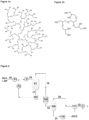
- Controlling the rate at which liquid GLC is fed into the evaporator also helps to avoid the evaporator from drying out, for example such that a liquid film is not continuous or properly maintained on an inner wall in the case of rising/falling film evaporators or agitated thin-film evaporators. Drying out of the liquid film on the inner wall of these evaporators not only prevents the formation of turbulent flow of liquid but also exacerbates the formation of by-products, such as solid hyperbranched polyether polyols (as shown in Figure 1a ), which may take the form of solid deposits in the evaporator.
- solid hyperbranched polyether polyols as shown in Figure 1a
- drying out of the evaporator may be a consequence of a majority of the decarboxylation promotor having evaporated without being adequately replenished. Remaining unreacted GLC may then undergo self-polymerisation forming polyols which cannot be terminated in the usual manner by virtue of the presence of the decarboxylation promotor as discussed hereinbefore. This therefore results in solids build-up. An absence of any flowing condensate liquid exiting out of the bottom of the evaporator also prevents any solids from being carried out of the evaporator, as may otherwise occur, further exacerbating solid build-up inside the evaporator. Thus, ensuring a constant liquid film on the inner wall of these evaporators reduces unwanted by-products and reduces the cleaning and maintenance requirements.
- the flow rate, in terms of feed mass / (surface area of reactor * time), at which the liquid feed stream comprising GLC is fed to the evaporator may suitably be in the range of from 0.001 to 0.250 kgm -2 s -1 .
- the flow rate is from 0.005 to 0.050 kgm -2 s - 1, preferably from 0.008 to 0.015 kgm -2 s -1 .
- any suitable means for feeding the liquid GLC and decarboxylation promotor to the evaporator may be used in accordance with the present invention.
- a pumping means is provided in order to pump the liquid phase mixture for feeding to the evaporator in a controlled manner and at a particular flow rate, although preferably one which is configured for use in connection with systems operating under vacuum and also preferably flow meter controlled.
- gear pump and backpressure regulator/overflow valve have been found to be particularly suitable for this purpose.
- An example of a suitable flowmeter controlled gear pump is the Bronkhorst ® gear pump with integrated Coriolis mini-CORI-FLOW TM mass flow meter available from Bronkhorst UK.
- rotor speed in an agitated thin-film evaporator can have a significant effect on shear strain rate and the level of turbulence provided to the liquid film therein.
- the rotor speed in the agitated thin-film evaporator is suitably greater than 25 rpm in order to ensure turbulent flow is provided by the fillet/bow wave created in the film by the wipers/blades.
- the rotor speed in the agitated thin-film evaporator is at least 50 rpm, more preferably at least 100 rpm, even more preferably at least 200 rpm and still more preferably at least 400 rpm.
- the rotor speed is less than 1500 rpm, more preferably less than 1250 rpm, even more preferably less than 1000 rpm.
- the rotor speed in the agitated thin-film evaporator is from 100 rpm to 1000 rpm, more preferably from 150 to 800 rpm, even more preferably from 200 to 600 rpm, most preferably from 250 rpm to 500 rpm.
- the process of the present invention may be operated at sub-atmospheric pressure or may be operated at atmospheric or elevated pressures together with a flow of an inert carrier gas (for example, nitrogen) for facilitating evaporation and driving off GLD vapours, for instance as an effluent stream from an agitated thin-film evaporator. Therefore, in step b) of the process, the gaseous GLD formed may flow out of the evaporator under the action of a vacuum or by virtue of a flow of inert gas.
- an inert carrier gas for example, nitrogen
- the process is operated at sub-atmospheric pressure.
- lowering the pressure at which the evaporator is operated lowers the temperature at which a particular rate of evaporation may be achievable and can also help reduce residence time and lessen by-product formation.
- the process of the invention, or an evaporator employed in the process is suitably operated at pressures up to 50.0 kPa absolute (500 mbar absolute), for instance from 0.1 kPa absolute (10 mbar absolute) to 50.0 kPa absolute (500 mbar absolute).
- the process of the invention is operated at a pressure of less than or equal to 20.0 kPa absolute (200 mbar absolute), preferably less than or equal to 15.0 kPa absolute (150 mbar absolute), more preferably less than or equal to 12.5 kPa absolute (125 mbar absolute) and most preferably less than or equal to 11.0 kPa absolute (110 mbar absolute).
- a particularly preferred range of pressure is from 0.5 kPa absolute (50 mbar absolute) to 20.0 kPa absolute (200 mbar absolute).
- the skilled person is able to select a suitable temperature range at which the process is operated based, for instance, on the desired evaporation rate of GLD and the volumetric flow of GLD-containing stream, for instance as an effluent from an evaporator.
- a suitable temperature range at which the process is operated based, for instance, on the desired evaporation rate of GLD and the volumetric flow of GLD-containing stream, for instance as an effluent from an evaporator.
- the skilled person is able to select the evaporator temperature depending on, for instance, the liquid GLC flow rate, rotor speed of the wipers/blades, the pressure under which the evaporator is operated and also based on whether the liquid GLC feed is preheated or not.
- suitable temperature ranges will preferably lead to a rate of evaporation that: i) avoids the liquid film being evaporated to dryness based on the flow rate; ii) minimises unwanted by-product formation; and iii) provides a desirable volumetric flow of gaseous GLD effluent from the evaporator.
- Suitable temperature and pressure ranges may also be selected to minimise any unwanted evaporation of unreacted GLC and/or decarboxylation promotor from the liquid phase reaction mixture together with the GLD. By minimising such stripping of unreacted GLC and/or decarboxylation promotor, purification of the crude GLD product stream is less onerous or possibly even unnecessary.
- Heating of the liquid GLC and decarboxylation promotor may be performed by any conventional means which is compatible with the means of evaporation employed (e.g. an evaporator). Examples include use of a circulating vapour or liquid heat transfer medium (for example, in a shell and tube heat exchanger configuration or in a jacketed heating system), use of band heaters or use of an inductive heating system employing wrap-around metal coils.
- a circulating vapour or liquid heat transfer medium for example, in a shell and tube heat exchanger configuration or in a jacketed heating system
- band heaters for example, in a shell and tube heat exchanger configuration or in a jacketed heating system
- an inductive heating system employing wrap-around metal coils.
- evaporation step c) of the process of the invention, or an evaporator employed in the process is operated at a temperature of from 125 °C to 300 °C, preferably from 190 °C to 275 °C, more preferably from 200 °C to 250 °C, even more preferably from 210 °C to 240 °C, and most preferably from 215 °C to 235 °C.
- operation temperature of the evaporator is considered to correspond to the internal temperature of the evaporator, for instance as measured by thermocouple, and not, for example, the temperature of the inlet to the evaporator.
- the liquid GLC and decarboxylation promotor are preheated prior to being introduced into the evaporator. Preheating of the liquid GLC can reduce the viscosity of GLC, making it easier to pump, and may also lessen the degree of heating required with respect to the evaporator, which may be more energy efficient overall and may also improve evaporation rates.
- the liquid GLC is preheated to a temperature of from 50 °C to 150 °C, preferably from 65 °C to 135 °C, more preferably from 75 °C to 125 °C.
- the GLD vapours formed therein may be withdrawn from the evaporator, for example, counter-currently or co-currently to the liquid feed, through an outlet, usually toward or at the top of the evaporator in the case of a vertical evaporator.
- the evaporator also comprises an outlet for liquid condensate (also known as a "residue"), usually located toward or at the bottom of the evaporator.
- a collector vessel may be present which collects the liquid condensate/residue withdrawn from the evaporator which includes any unreacted GLC and decarboxylation promotor.
- unreacted GLC and/or decarboxylation promotor withdrawn from the evaporator as part of a liquid condensate/residue is recycled to the feed for the evaporator.
- a pumping means may be provided in order to transfer unreacted GLC and/or decarboxylation promotor from a collector vessel to the feed stream during the process.
- liquid GLC may pass through the evaporator a number of times before being reacted to form GLD.
- a gear pump is utilized, preferably a flow meter controlled gear pump, in order to recycle the unreacted GLC withdrawn from the evaporator back to the feed, preferably wherein recycling is operated on a continuous basis.
- a gaseous effluent stream from the evaporator comprising GLD vapours may be passed to a condenser for condensing condensable components of the gaseous effluent stream.
- suitable condensers include liquid-cooled surface condensers, which may be operated in transverse, parallel or counter flow.
- Non-condensables, for example carbon dioxide by-product, may be separated by using a gas-liquid separator downstream of the condenser.
- CO 2 vapours produced by the decarboxylation reaction may be vented through the vacuum pump or fed to a CO 2 scrubber before being conveyed to downstream processes for capture and appropriate disposal.
- a cold condensation trap may also be utilised upstream of the vacuum pump so as to condense any remaining condensable vapours which may be detrimental to the vacuum pump.
- a GLD liquid product stream may therefore be collected in a vessel.
- the GLD product may undergo purification in order to remove unwanted by-products and/or any unreacted GLC or decarboxylation promotor that may have been stripped from the liquid phase reaction mixture together with the GLD.
- final purification of the GLD obtained by the process of the invention is by thin film evaporation.
- any unreacted GLC and decarboxylation promotor obtained as result of the GLD purification may be recycled back to a feed stream to the evaporator, if desired.
- GLY glycerol
- GLD product may be isolated from GLY, diglycerol and unreacted GLC by separation using distillation or thin film evaporation.
- Any suitable reactive distillation column may be used provided that it has a number of stages (e.g. ideal stages) commensurate with the separation desired, for example fromt 1 to 10 ideal separation stages.
- one or more separation steps may also be employed to ensure adequate separation of GLD product from the crude material.
- Any of the agitated thin film evaporators discussed hereinbefore may be conveniently used for purification of the GLD product by thin film evaporation.
- any glycerol that is isolated by means of the separation may be recycled to a GLC preparation process, such as the preferred GLC preparation process described hereinafter.
- the glycerol may be fed back to contacting step i) of the process, for instance a feed stream to an agitated thin-film evaporator employed in the process.
- any unreacted GLC that is isolated following purification of the crude product of the process may be recycled back to contacting step i) of the process, for instance, as a feed stream for an agitated thin-film evaporator employed in the process.
- the process of the present invention has been found to afford only minor by-product formation and is capable of completely avoiding the production of high molecular weight by-products that are potentially damaging to process equipment.
- minor by-products of the present invention have been found to take the form of low molecular weight oligomers of glycerol, for instance, having from 2 to 5 repeat monomer units.
- An example of a low molecular weight oligomer of glycerol having 5 repeat monomer units is shown in Figure 1b .
- this by-product may in fact be repurposed and used as the decarboxylation promotor in the reaction.
- Oligomers of glycerol are also useful as polymer additives (for example in polyesters), food additives (as polyglycerol esters), defoaming agents, as well as shale inhibitors in drilling fluids. Therefore, these by-products of the present invention can advantageously provide a further revenue stream in their own right and may be isolated from the crude product mixture by the separation techniques discussed herein.
- the process of the invention also comprises the formation of an oligomer of glycerol having from 2 to 8 monomer units, preferably from 2 to 5 monomer units, as a minor by-product.
- the yield of this by-product may be from 1 to 15 mol.%, preferably from 1 to 10 mol.%, more preferably from 1 to 5 mol.%.
- this by-product is recycled to the decarboxylation reaction for use as a decarboxylation promotor.
- this by-product is isolated from the crude product mixture for utilising as a commodity chemical.
- the process of the present invention may be performed as a batch or preferably as a continuous process. Operating on a continuous basis is also facilitated based on there being no requirement for catalyst regeneration or solvent replacement.
- the process of the present invention advantageously obviates the need for a decarboxylation catalyst that has typically been employed in prior art processes. This is particularly beneficial in terms of simplifying reactor design, simplifying the isolation and purification of product, reducing capital costs associated with providing and maintaining catalyst beds and also reducing maintenance and cleaning requirements of the process equipment. Therefore, so as to take full advantage of the benefits of the present invention, no decarboxylation catalyst is used to catalyse the decarboxylation reaction.
- no solvents or other diluents, other than the decarboxylation promotor are used which may be supplied with the GLC reactant.
- the solvent is an inert solvent having no active hydrogens, for example, polyethylene glycol dimethyl ether or dibenzyl ether.
- the presence of the decarboxylation promotor not only acts to increase selectivity toward the decarboxylation of GLC, it also acts a GLC self-polymerisation inhibitor, by acting as a chain terminator thereby increasing selectivity toward for the formation of glycidol and thereby substantially reducing the formation of unwanted polymeric by-products, such as polyglycerols and poly(glycerol carbonate).
- the decarboxylation promotor not only acts to increase selectivity toward the decarboxylation of GLC, it also acts a GLC self-polymerisation inhibitor, by acting as a chain terminator thereby increasing selectivity toward for the formation of glycidol and thereby substantially reducing the formation of unwanted polymeric by-products, such as polyglycerols and poly(glycerol carbonate).
- the yield of GLD in the process of the invention is at least 60 mol.%, more preferably at least 70 mol.%, most preferably at least 75 mol.%, as measured using NMR, for instance, 1 H-NMR.
- the level of GLC conversion is at least 90 mol.%, preferably at least 95 mol.%, more preferably at least 98 mol.%. In some embodiments where an evaporator is employed, this level of conversion is achieved through recycling of unreacted GLC obtained from the evaporator to the feed.
- GLC employed in the process of the present invention may be prepared by known processes.
- GLC may be prepared from transesterification of GLY and dialkyl carbonate or cyclic alkylene carbonate, as illustrated below in Schemes A and B.
- a GLC reactant stream utilized in the present invention has the highest purity possible.
- the purity of a GLC reactant stream used in the process of the present invention is at least 95 %, more preferably at least 96 %, even more preferably at least 97 %, still more preferably at least 98 % and most preferably the GLC reactant stream has a purity of at least 99 %, as measured according to HPLC.
- GLC for use in the present invention is readily available from suppliers such as Innospec Colorado, US) and UBE Industries Ltd (Japan).
- methods for preparing GLC involve direct carbonylation of glycerol.
- Other common synthetic routes involve transesterification of dialkyl carbonates or cyclic alkylene carbonates with glycerol.
- the GLC used in the decarboxylation reaction of the present invention is prepared by a method comprising the steps of:
- the process for preparing GLC according to the above method involves a transesterification reaction between GLY and dialkyl carbonate or cyclic alkylene carbonate, leading to the formation of GLC and alcohol by-product, as illustrated below in Schemes C and D.
- selectivity for GLC in the subsequent reaction in step (iii) of the above method which follows the alcohol separation step (ii) may be increased by ensuring that the subsequent reaction is performed with continuous by-product alcohol removal. It has been found that by incorporating continuous removal into the final stage of the reaction the overall selectivity for GLC increases. Without being bound by any particular theory, it is believed that formation of glycerol dicarbonate occurs more readily in the subsequent reaction in step (iii) following the methanol separation step (ii), as illustrated in Scheme E below.
- step (iii) By employing continuous by-product alcohol removal in the final stage reaction in step (iii), it has been found that the equilibrium can be shifted towards the formation of the desired GLC, as illustrated in Scheme F below.
- the combination of the intermediate by-product alcohol separation step (ii) followed by continuous by-product alcohol removal in the subsequent reaction step (iii) may therefore maximise both conversion as well as selectivity for GLC.
- the present invention also provides a process for the preparation of propylene oxide by the thermal decarboxylation of propylene carbonate, said process comprising the steps of:
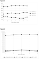
- a mixed liquid glycerol carbonate (GLC) and decarboxylation promotor (DP) feed stream (15) may be pumped (P1), for instance by means of a gear pump, to an agitated thin-film evaporator (E1) for heating and separation of formed glycidol (GLD) by evaporation in accordance with the method of the invention.
- the mixed liquid glycerol carbonate (GLC) and decarboxylation promotor (DP) feed stream (15) may be pre-heated by means of a preheater (H) to produce a preheated mixed feed stream (16).
- the evaporator (E1) is preferably in the form of a vertical and cylindrical agitated thin-film evaporator with wipers or blades.
- the heated mixed liquid glycerol carbonate (GLC) and decarboxylation promotor (DP) stream (16) is fed into the evaporator (E1), it is evenly distributed on the inner wall of the evaporator (E1) by the rotating blades/wipers before the thickness of the film grows such that turbulent flow develops, allowing optimum heat flux through the liquid and mass transfer to the vapour phase.
- the volumetric flow rate of the liquid feed stream is increased so that the thickness of the film on the inner walls of the evaporator (E1) exceeds the thickness of the clearance between the blades/wipers and the inner wall of the evaporator (E1), the movement of the blades/wipers creates a fillet/bow wave in the film, giving rise to turbulent flow.
- the glycerol carbonate (GLC) fed into the evaporator (E1) undergoes thermal decaboxylation in the presence of the decarboxylation promotor to form glycidol (GLD) and carbon dioxide.
- the glycidol (GLD) formed rapidly evaporates to the gas phase and is extracted counter-currently or co-currently to the liquid entering the evaporator (E1) under reduced pressure, provided by vacuum pump (V).
- evaporated glycidol (GLD) may be forced out of the evaporator (E1) using an inert carrier gas (for example, nitrogen).
- a liquid effluent stream (17) is also extracted from the evaporator (E1) which comprises non-volatile material and unreacted glycerol carbonate (GLC), which may be collected in a collector vessel (107).
- the unreacted glycerol carbonate (GLC) in the collector vessel (107) may be recycled to the liquid glycerol carbonate feed stream (15) by means of a pump (P2), which is preferably a gear pump.
- a gaseous glycidol (GLD) effluent stream (18) from the evaporator (E1) is subsequently passed to a condenser (108) which condenses condensable vapours, primarily glycidol product, to form a mixed gas-liquid stream (19) which is subsequently fed to a gas-liquid separator (109).
- the gaseous portion which is primarily carbon dioxide, is withdrawn as stream (20) from the separator (109) and is passed through a cold condensation trap (111) which condenses any remaining condensable vapours which may be detrimental to the vacuum pump (V) located downstream.
- the carbon dioxide waste stream (22) may subsequently be conveyed to downstream processes for capture and appropriate disposal.
- a liquid stream (21) corresponding to a crude glycidol product is withdrawn from the separator (109) and is stored in vessel (110).
- the crude glycidol product in vessel (110) may be passed on to a distillation column or to another agitated thin-film evaporator for further purification. Any glycerol carbonate (GLC) or decarboxylation promotor impurity isolated following purification may also be recycled back to the feed stream (15).
- GLC glycerol carbonate
- decarboxylation promotor impurity isolated following purification may also be recycled back to the feed stream (15).
- the distillate stream was analysed by 1 H NMR spectroscopy while the residue was analysed by HPLC using a refractive index detector.
- NMR solvent used was D 6 -DMSO, with acetonitrile internal standard.
- the stationary phase used for the HPLC was an organic acids column (Phenomenex Rezex ROA - Organic Acids H + ), the mobile phase was 7.5 % acetonitrile, 0.5 mM aqueous H 2 SO 4 and ethylene glycol was employed as an internal standard.
- a UIC DSL-5 wiped film glass evaporator was heated to a temperature of 230 °C using stainless steel band clamp heaters and connected, by means of a counter-current outlet, to a vacuum pump which was operated to maintain the system at a pressure of 100 mbar and a cold trap was placed before the vacuum pump to eliminate product loss.
- a residue outlet of the evaporator was equipped with a gear pump and a back pressure regulator so as to remove residue liquid from the bottom of the evaporator whilst the vapour outlet at the top of the evaporator connected to a coiled condenser and a receiver vessel to which vapours from the evaporator were fed, counter-currently to the liquid feed.
- the receiver vessel also included an outlet gear pump and back pressure regulator valve.
- Decarboxylation promotor (GLY) and GLC (3.3 kg) were mixed in a molar ratio of 75 : 25 and fed from a feeding vessel to the top the evaporator at an approximate rate of 1.2 kg/h using a pump and the rotor speed of the evaporator was set to 400 RPM.
- Continuous recycle of residue in the residue collector vessel to the feeding vessel was employed by pumping directly from the residue collector vessel to the feeding vessel for the evaporator using a gear pump.
- a separate supply of decarboxylation promotor (GLY) was also continuously added to the feeding vessel, at a rate of 180 g/h, to accommodate for loss of decarboxylation promotor from the evaporator through evaporation.
- the composition of the distillate obtained in the receiver vessel was repeatedly measured over the course of the experiment, the results of which are shown in Figure 3 .
- the results show that a glycidol concentration of approximately 60 mol.% was maintained over the course of the experiment, with the remaining components being unreacted GLC and decarboxylation promotor (GLY) which evaporated from the liquid phase reaction mixture with GLD.
- GLY decarboxylation promotor
- Example 2 The experiment according to Example 1 was repeated, except that the evaporator was heated to a temperature of 270 °C and operated at atmospheric pressure (1013 mbar) and the rate of supplemental decarboxylation promotor (GLY) addition to the feeding vessel was at a rate of 120 g/h, to accommodate for loss of decarboxylation promotor from the evaporator through evaporation.
- GLY supplemental decarboxylation promotor
- the composition of the distillate obtained in the receiver vessel was repeatedly measured over the course of the experiment, as in Example 1, and the results of which are shown in Figure 4 .
- the results show that a glycidol concentration of approximately 80 mol.% was maintained over the course of the experiment, with only minor amounts of unreacted GLC and decarboxylation promotor (GLY) contained in the distillate.
- Figure 4 also shows the evaporation rate in the evaporator as a fraction of the total feed. As can be seen, the evaporation rate slowly rises and falls over the course of the experiment.
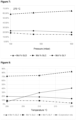
- Example 1 The experiment according to Example 1 was repeated, except that several different combinations of evaporator temperatures (230, 250 and 270 °C) and pressures (100, 250, 350 and 500 mbar) were tested in a series of experiments and without recycle of residue.
- the composition of the distillate was assessed during each of the different experiments, and after only a single pass through the evaporator, to determine the extent of GLD formation and the degree of evaporation of unreacted GLC and decarboxylation promotor from the liquid phase mixture.
- Figures 5 to 7 show the results of the distillate compositional analysis for a particular evaporator temperature over the different pressures tested. At each of the evaporator temperatures tested, improvement in GLD yield is seen from increasing the pressure of the evaporator from 100 mbar to 500 mbar. The results also show that at lower temperatures, the rate of distillation of decarboxylation promotor (GLY) and GLC is more sensitive to pressure than at higher temperatures. For example, at an evaporator temperature of 230 °C ( Figure 5 ) the amount of decarboxylation promotor (GLY) which is distilled decreases from 27% to 7% upon increasing the pressure from 100 to 500 mbar.
- GLY decarboxylation promotor
- Example 1 The experiment according to Example 1 was repeated, except that several different combinations of evaporator temperatures (200, 210 and 220 °C) and pressures (100 and 500 mbar) were tested in a series of experiments, the feed flow rate was lowered to 0.3 kg/h and experiments performed without recycle of residue.
- the composition of the distillate was assessed, after only one "pass" through the evaporator, during each of the different experiments to determine the extent of GLD formation and the degree of evaporation of unreacted GLC and decarboxylation promotor from the liquid phase mixture.
- FIGS 8 and 9 show the results of the distillate compositional analysis for a particular evaporator pressure (100 mbar and 500 mbar, respectively) over the different temperatures tested, after only one "pass" through the evaporator. Unwanted GLC evaporation was substantially reduced in these experiments. By changing the temperature of the evaporator from 230 °C (Example 3) to 220 °C and the feed flow rate from 1.2 kg/h (Example 3) to 0.3 kg/h the composition of GLC in the distillate was reduced from 12 to 3 mol%. These experiments therefore show that a good level of GLD yield is achievable over different feed flow rates and evaporator temperatures and that system conditions can be readily modified to improve yield of GLD further.
- Example 5 Batch Process With Wiped Film Evaporator and Recycle of Residue Using Different Decarboxylation Promotors
- Example 2 The experiment according to Example 1 was repeated, except that several different decarboxylation promotors were mixed in a 75 : 25 molar ratio (GLC : Decarboxylation Promotor) and the GLC source contained 5 mol.% of glycerol contaminant. Additionally, the condensate residue from the evaporator was collected following each pass of all of the GLC reactant from the feed vessel through the evaporator before being recycled back to the feed vessel for further "passes" throught the evaporator until such time as either no further distillate was collected or solids formation in the evaporator was evident.
- GLC Decarboxylation Promotor
Landscapes
- Chemical & Material Sciences (AREA)
- Organic Chemistry (AREA)
- Epoxy Compounds (AREA)
- Organic Low-Molecular-Weight Compounds And Preparation Thereof (AREA)
- Vaporization, Distillation, Condensation, Sublimation, And Cold Traps (AREA)
- Low-Molecular Organic Synthesis Reactions Using Catalysts (AREA)
Applications Claiming Priority (2)
| Application Number | Priority Date | Filing Date | Title |
|---|---|---|---|
| GB1805029.4A GB2572385B (en) | 2018-03-28 | 2018-03-28 | Process for the preparation of glycidol |
| PCT/GB2019/050904 WO2019186180A1 (en) | 2018-03-28 | 2019-03-28 | Process for the preparation of glycidol |
Publications (2)
| Publication Number | Publication Date |
|---|---|
| EP3774752A1 EP3774752A1 (en) | 2021-02-17 |
| EP3774752B1 true EP3774752B1 (en) | 2024-07-24 |
Family
ID=62067971
Family Applications (1)
| Application Number | Title | Priority Date | Filing Date |
|---|---|---|---|
| EP19716513.7A Active EP3774752B1 (en) | 2018-03-28 | 2019-03-28 | Process for the preparation of glycidol |
Country Status (12)
| Country | Link |
|---|---|
| US (1) | US11472783B2 (pl) |
| EP (1) | EP3774752B1 (pl) |
| JP (1) | JP7511255B2 (pl) |
| KR (1) | KR102773640B1 (pl) |
| CN (1) | CN112334452B (pl) |
| CA (1) | CA3095623A1 (pl) |
| ES (1) | ES2989312T3 (pl) |
| FI (1) | FI3774752T3 (pl) |
| GB (1) | GB2572385B (pl) |
| MY (1) | MY205330A (pl) |
| PL (1) | PL3774752T3 (pl) |
| WO (1) | WO2019186180A1 (pl) |
Families Citing this family (1)
| Publication number | Priority date | Publication date | Assignee | Title |
|---|---|---|---|---|
| CN112763601A (zh) * | 2020-12-24 | 2021-05-07 | 福元药业有限公司 | 一种测定开塞露原料中环氧丙醇的方法 |
Family Cites Families (6)
| Publication number | Priority date | Publication date | Assignee | Title |
|---|---|---|---|---|
| US2636040A (en) * | 1950-10-06 | 1953-04-21 | Ind Rayon Corp | Method of preparing glycidol |
| FR2760747B1 (fr) * | 1997-03-12 | 1999-06-04 | Organisation Nationale Interpr | Procede de fabrication de glycidol ou d'un compose glycidyle |
| JP2009149576A (ja) * | 2007-12-21 | 2009-07-09 | Kao Corp | グリシドールの製造方法 |
| US7868192B1 (en) * | 2009-07-15 | 2011-01-11 | Kao Corporation | Process for producing glycidol |
| JP6291325B2 (ja) * | 2014-04-04 | 2018-03-14 | 花王株式会社 | グリシドールの製造方法 |
| ES2603643B1 (es) * | 2015-07-30 | 2017-12-13 | Fundacion Tecnalia Research & Innovation | Procedimiento para sintetizar glicidol |
-
2018
- 2018-03-28 GB GB1805029.4A patent/GB2572385B/en active Active
-
2019
- 2019-03-28 JP JP2021501110A patent/JP7511255B2/ja active Active
- 2019-03-28 MY MYPI2020005004A patent/MY205330A/en unknown
- 2019-03-28 KR KR1020207031029A patent/KR102773640B1/ko active Active
- 2019-03-28 US US17/042,309 patent/US11472783B2/en active Active
- 2019-03-28 PL PL19716513.7T patent/PL3774752T3/pl unknown
- 2019-03-28 ES ES19716513T patent/ES2989312T3/es active Active
- 2019-03-28 CN CN201980036245.0A patent/CN112334452B/zh active Active
- 2019-03-28 EP EP19716513.7A patent/EP3774752B1/en active Active
- 2019-03-28 FI FIEP19716513.7T patent/FI3774752T3/fi active
- 2019-03-28 CA CA3095623A patent/CA3095623A1/en active Pending
- 2019-03-28 WO PCT/GB2019/050904 patent/WO2019186180A1/en not_active Ceased
Also Published As
| Publication number | Publication date |
|---|---|
| CN112334452B (zh) | 2024-07-16 |
| GB2572385B (en) | 2023-05-31 |
| FI3774752T3 (fi) | 2024-08-14 |
| JP2021519348A (ja) | 2021-08-10 |
| JP7511255B2 (ja) | 2024-07-05 |
| CN112334452A (zh) | 2021-02-05 |
| BR112020019545A2 (pt) | 2021-01-05 |
| US20210017142A1 (en) | 2021-01-21 |
| ES2989312T3 (es) | 2024-11-26 |
| PL3774752T3 (pl) | 2024-11-18 |
| US11472783B2 (en) | 2022-10-18 |
| CA3095623A1 (en) | 2019-10-03 |
| KR20210005029A (ko) | 2021-01-13 |
| GB201805029D0 (en) | 2018-05-09 |
| WO2019186180A1 (en) | 2019-10-03 |
| EP3774752A1 (en) | 2021-02-17 |
| KR102773640B1 (ko) | 2025-02-27 |
| MY205330A (en) | 2024-10-16 |
| GB2572385A (en) | 2019-10-02 |
Similar Documents
| Publication | Publication Date | Title |
|---|---|---|
| US8471077B2 (en) | Process and apparatus for efficient recovery of dichlorohydrins | |
| US20100137652A1 (en) | Multi-stage process and apparatus for recovering dichlorohydrins | |
| US8629305B2 (en) | Process and apparatus for azeotropic recovery of dichlorohydrins | |
| US8926916B2 (en) | Process and apparatus for recovery of dichlorohydrins via codistillation | |
| US9963436B2 (en) | Process for the manufacture of epoxy-monomers and epoxides | |
| US8334415B2 (en) | Process and apparatus for reducing heavy byproduct formation during distillation | |
| KR101116520B1 (ko) | 폐 스트림 회수 방법 및 장치 | |
| EP3774752B1 (en) | Process for the preparation of glycidol | |
| US8298500B2 (en) | Process and apparatus for producing and purifying epichlorohydrins | |
| US8586802B2 (en) | Multi-stage process and apparatus for recovering dichlorohydrins | |
| BR112020019545B1 (pt) | Processo para a preparação de glicidol por descarboxilação térmica de carbonato de glicerol, e, uso de um mono-ol, um poliol ou misturas dos mesmos | |
| EP2215045B1 (en) | Method of preparing a purified ester-substituted phenol stream |
Legal Events
| Date | Code | Title | Description |
|---|---|---|---|
| STAA | Information on the status of an ep patent application or granted ep patent |
Free format text: STATUS: UNKNOWN |
|
| STAA | Information on the status of an ep patent application or granted ep patent |
Free format text: STATUS: THE INTERNATIONAL PUBLICATION HAS BEEN MADE |
|
| PUAI | Public reference made under article 153(3) epc to a published international application that has entered the european phase |
Free format text: ORIGINAL CODE: 0009012 |
|
| STAA | Information on the status of an ep patent application or granted ep patent |
Free format text: STATUS: REQUEST FOR EXAMINATION WAS MADE |
|
| 17P | Request for examination filed |
Effective date: 20201028 |
|
| AK | Designated contracting states |
Kind code of ref document: A1 Designated state(s): AL AT BE BG CH CY CZ DE DK EE ES FI FR GB GR HR HU IE IS IT LI LT LU LV MC MK MT NL NO PL PT RO RS SE SI SK SM TR |
|
| AX | Request for extension of the european patent |
Extension state: BA ME |
|
| DAV | Request for validation of the european patent (deleted) | ||
| DAX | Request for extension of the european patent (deleted) | ||
| STAA | Information on the status of an ep patent application or granted ep patent |
Free format text: STATUS: EXAMINATION IS IN PROGRESS |
|
| 17Q | First examination report despatched |
Effective date: 20211014 |
|
| GRAP | Despatch of communication of intention to grant a patent |
Free format text: ORIGINAL CODE: EPIDOSNIGR1 |
|
| STAA | Information on the status of an ep patent application or granted ep patent |
Free format text: STATUS: GRANT OF PATENT IS INTENDED |
|
| INTG | Intention to grant announced |
Effective date: 20240209 |
|
| GRAS | Grant fee paid |
Free format text: ORIGINAL CODE: EPIDOSNIGR3 |
|
| GRAA | (expected) grant |
Free format text: ORIGINAL CODE: 0009210 |
|
| STAA | Information on the status of an ep patent application or granted ep patent |
Free format text: STATUS: THE PATENT HAS BEEN GRANTED |
|
| RBV | Designated contracting states (corrected) |
Designated state(s): AL AT BE BG CH CY CZ DE DK EE ES FI FR GR HR HU IE IS IT LI LT LU LV MC MK MT NL NO PL PT RO RS SE SI SK SM TR |
|
| AK | Designated contracting states |
Kind code of ref document: B1 Designated state(s): AL AT BE BG CH CY CZ DE DK EE ES FI FR GR HR HU IE IS IT LI LT LU LV MC MK MT NL NO PL PT RO RS SE SI SK SM TR |
|
| REG | Reference to a national code |
Ref country code: CH Ref legal event code: EP |
|
| REG | Reference to a national code |
Ref country code: FI Ref legal event code: FGE Ref country code: IE Ref legal event code: FG4D Ref country code: DE Ref legal event code: R096 Ref document number: 602019055663 Country of ref document: DE |
|
| REG | Reference to a national code |
Ref country code: NL Ref legal event code: FP |
|
| REG | Reference to a national code |
Ref country code: LT Ref legal event code: MG9D |
|
| REG | Reference to a national code |
Ref country code: ES Ref legal event code: FG2A Ref document number: 2989312 Country of ref document: ES Kind code of ref document: T3 Effective date: 20241126 |
|
| PG25 | Lapsed in a contracting state [announced via postgrant information from national office to epo] |
Ref country code: PT Free format text: LAPSE BECAUSE OF FAILURE TO SUBMIT A TRANSLATION OF THE DESCRIPTION OR TO PAY THE FEE WITHIN THE PRESCRIBED TIME-LIMIT Effective date: 20241125 |
|
| REG | Reference to a national code |
Ref country code: AT Ref legal event code: MK05 Ref document number: 1706229 Country of ref document: AT Kind code of ref document: T Effective date: 20240724 |
|
| PG25 | Lapsed in a contracting state [announced via postgrant information from national office to epo] |
Ref country code: PT Free format text: LAPSE BECAUSE OF FAILURE TO SUBMIT A TRANSLATION OF THE DESCRIPTION OR TO PAY THE FEE WITHIN THE PRESCRIBED TIME-LIMIT Effective date: 20241125 |
|
| PG25 | Lapsed in a contracting state [announced via postgrant information from national office to epo] |
Ref country code: NO Free format text: LAPSE BECAUSE OF FAILURE TO SUBMIT A TRANSLATION OF THE DESCRIPTION OR TO PAY THE FEE WITHIN THE PRESCRIBED TIME-LIMIT Effective date: 20241024 |
|
| PG25 | Lapsed in a contracting state [announced via postgrant information from national office to epo] |
Ref country code: GR Free format text: LAPSE BECAUSE OF FAILURE TO SUBMIT A TRANSLATION OF THE DESCRIPTION OR TO PAY THE FEE WITHIN THE PRESCRIBED TIME-LIMIT Effective date: 20241025 |
|
| PG25 | Lapsed in a contracting state [announced via postgrant information from national office to epo] |
Ref country code: BG Free format text: LAPSE BECAUSE OF FAILURE TO SUBMIT A TRANSLATION OF THE DESCRIPTION OR TO PAY THE FEE WITHIN THE PRESCRIBED TIME-LIMIT Effective date: 20240724 |
|
| PG25 | Lapsed in a contracting state [announced via postgrant information from national office to epo] |
Ref country code: LV Free format text: LAPSE BECAUSE OF FAILURE TO SUBMIT A TRANSLATION OF THE DESCRIPTION OR TO PAY THE FEE WITHIN THE PRESCRIBED TIME-LIMIT Effective date: 20240724 |
|
| PG25 | Lapsed in a contracting state [announced via postgrant information from national office to epo] |
Ref country code: IS Free format text: LAPSE BECAUSE OF FAILURE TO SUBMIT A TRANSLATION OF THE DESCRIPTION OR TO PAY THE FEE WITHIN THE PRESCRIBED TIME-LIMIT Effective date: 20241124 Ref country code: AT Free format text: LAPSE BECAUSE OF FAILURE TO SUBMIT A TRANSLATION OF THE DESCRIPTION OR TO PAY THE FEE WITHIN THE PRESCRIBED TIME-LIMIT Effective date: 20240724 |
|
| PG25 | Lapsed in a contracting state [announced via postgrant information from national office to epo] |
Ref country code: HR Free format text: LAPSE BECAUSE OF FAILURE TO SUBMIT A TRANSLATION OF THE DESCRIPTION OR TO PAY THE FEE WITHIN THE PRESCRIBED TIME-LIMIT Effective date: 20240724 |
|
| PG25 | Lapsed in a contracting state [announced via postgrant information from national office to epo] |
Ref country code: NO Free format text: LAPSE BECAUSE OF FAILURE TO SUBMIT A TRANSLATION OF THE DESCRIPTION OR TO PAY THE FEE WITHIN THE PRESCRIBED TIME-LIMIT Effective date: 20241024 Ref country code: LV Free format text: LAPSE BECAUSE OF FAILURE TO SUBMIT A TRANSLATION OF THE DESCRIPTION OR TO PAY THE FEE WITHIN THE PRESCRIBED TIME-LIMIT Effective date: 20240724 Ref country code: IS Free format text: LAPSE BECAUSE OF FAILURE TO SUBMIT A TRANSLATION OF THE DESCRIPTION OR TO PAY THE FEE WITHIN THE PRESCRIBED TIME-LIMIT Effective date: 20241124 Ref country code: HR Free format text: LAPSE BECAUSE OF FAILURE TO SUBMIT A TRANSLATION OF THE DESCRIPTION OR TO PAY THE FEE WITHIN THE PRESCRIBED TIME-LIMIT Effective date: 20240724 Ref country code: GR Free format text: LAPSE BECAUSE OF FAILURE TO SUBMIT A TRANSLATION OF THE DESCRIPTION OR TO PAY THE FEE WITHIN THE PRESCRIBED TIME-LIMIT Effective date: 20241025 Ref country code: BG Free format text: LAPSE BECAUSE OF FAILURE TO SUBMIT A TRANSLATION OF THE DESCRIPTION OR TO PAY THE FEE WITHIN THE PRESCRIBED TIME-LIMIT Effective date: 20240724 Ref country code: AT Free format text: LAPSE BECAUSE OF FAILURE TO SUBMIT A TRANSLATION OF THE DESCRIPTION OR TO PAY THE FEE WITHIN THE PRESCRIBED TIME-LIMIT Effective date: 20240724 |
|
| PGFP | Annual fee paid to national office [announced via postgrant information from national office to epo] |
Ref country code: DE Payment date: 20250327 Year of fee payment: 7 |
|
| PG25 | Lapsed in a contracting state [announced via postgrant information from national office to epo] |
Ref country code: SM Free format text: LAPSE BECAUSE OF FAILURE TO SUBMIT A TRANSLATION OF THE DESCRIPTION OR TO PAY THE FEE WITHIN THE PRESCRIBED TIME-LIMIT Effective date: 20240724 Ref country code: DK Free format text: LAPSE BECAUSE OF FAILURE TO SUBMIT A TRANSLATION OF THE DESCRIPTION OR TO PAY THE FEE WITHIN THE PRESCRIBED TIME-LIMIT Effective date: 20240724 Ref country code: RO Free format text: LAPSE BECAUSE OF FAILURE TO SUBMIT A TRANSLATION OF THE DESCRIPTION OR TO PAY THE FEE WITHIN THE PRESCRIBED TIME-LIMIT Effective date: 20240724 |
|
| PGFP | Annual fee paid to national office [announced via postgrant information from national office to epo] |
Ref country code: FI Payment date: 20250327 Year of fee payment: 7 Ref country code: NL Payment date: 20250327 Year of fee payment: 7 |
|
| PG25 | Lapsed in a contracting state [announced via postgrant information from national office to epo] |
Ref country code: EE Free format text: LAPSE BECAUSE OF FAILURE TO SUBMIT A TRANSLATION OF THE DESCRIPTION OR TO PAY THE FEE WITHIN THE PRESCRIBED TIME-LIMIT Effective date: 20240724 |
|
| PGFP | Annual fee paid to national office [announced via postgrant information from national office to epo] |
Ref country code: CZ Payment date: 20250327 Year of fee payment: 7 Ref country code: FR Payment date: 20250331 Year of fee payment: 7 Ref country code: PL Payment date: 20250328 Year of fee payment: 7 |
|
| REG | Reference to a national code |
Ref country code: DE Ref legal event code: R097 Ref document number: 602019055663 Country of ref document: DE |
|
| PG25 | Lapsed in a contracting state [announced via postgrant information from national office to epo] |
Ref country code: SK Free format text: LAPSE BECAUSE OF FAILURE TO SUBMIT A TRANSLATION OF THE DESCRIPTION OR TO PAY THE FEE WITHIN THE PRESCRIBED TIME-LIMIT Effective date: 20240724 |
|
| PLBE | No opposition filed within time limit |
Free format text: ORIGINAL CODE: 0009261 |
|
| STAA | Information on the status of an ep patent application or granted ep patent |
Free format text: STATUS: NO OPPOSITION FILED WITHIN TIME LIMIT |
|
| 26N | No opposition filed |
Effective date: 20250425 |
|
| PGFP | Annual fee paid to national office [announced via postgrant information from national office to epo] |
Ref country code: ES Payment date: 20250408 Year of fee payment: 7 |
|
| PGFP | Annual fee paid to national office [announced via postgrant information from national office to epo] |
Ref country code: IT Payment date: 20250327 Year of fee payment: 7 |
|
| PG25 | Lapsed in a contracting state [announced via postgrant information from national office to epo] |
Ref country code: SE Free format text: LAPSE BECAUSE OF FAILURE TO SUBMIT A TRANSLATION OF THE DESCRIPTION OR TO PAY THE FEE WITHIN THE PRESCRIBED TIME-LIMIT Effective date: 20240724 |
|
| PG25 | Lapsed in a contracting state [announced via postgrant information from national office to epo] |
Ref country code: MC Free format text: LAPSE BECAUSE OF FAILURE TO SUBMIT A TRANSLATION OF THE DESCRIPTION OR TO PAY THE FEE WITHIN THE PRESCRIBED TIME-LIMIT Effective date: 20240724 |
|
| REG | Reference to a national code |
Ref country code: CH Ref legal event code: H13 Free format text: ST27 STATUS EVENT CODE: U-0-0-H10-H13 (AS PROVIDED BY THE NATIONAL OFFICE) Effective date: 20251024 |
|
| PG25 | Lapsed in a contracting state [announced via postgrant information from national office to epo] |
Ref country code: LU Free format text: LAPSE BECAUSE OF NON-PAYMENT OF DUE FEES Effective date: 20250328 |