EP3774581B1 - Système d'application à étanchéité améliorée - Google Patents
Système d'application à étanchéité améliorée Download PDFInfo
- Publication number
- EP3774581B1 EP3774581B1 EP20700555.4A EP20700555A EP3774581B1 EP 3774581 B1 EP3774581 B1 EP 3774581B1 EP 20700555 A EP20700555 A EP 20700555A EP 3774581 B1 EP3774581 B1 EP 3774581B1
- Authority
- EP
- European Patent Office
- Prior art keywords
- outlet
- accessory
- cartridge
- seal
- sealing
- Prior art date
- Legal status (The legal status is an assumption and is not a legal conclusion. Google has not performed a legal analysis and makes no representation as to the accuracy of the status listed.)
- Active
Links
- 238000007789 sealing Methods 0.000 claims description 114
- 239000000463 material Substances 0.000 claims description 56
- 230000004323 axial length Effects 0.000 claims description 16
- 230000003068 static effect Effects 0.000 claims description 10
- -1 polypropylene Polymers 0.000 description 18
- 239000004743 Polypropylene Substances 0.000 description 9
- 229920001155 polypropylene Polymers 0.000 description 9
- 229930040373 Paraformaldehyde Natural products 0.000 description 3
- 239000004698 Polyethylene Substances 0.000 description 3
- 239000003365 glass fiber Substances 0.000 description 3
- 238000004519 manufacturing process Methods 0.000 description 3
- 229920000573 polyethylene Polymers 0.000 description 3
- 229920006324 polyoxymethylene Polymers 0.000 description 3
- 230000015572 biosynthetic process Effects 0.000 description 2
- 229920001577 copolymer Polymers 0.000 description 2
- 230000000694 effects Effects 0.000 description 2
- 239000004033 plastic Substances 0.000 description 2
- 229920003023 plastic Polymers 0.000 description 2
- 229920001707 polybutylene terephthalate Polymers 0.000 description 2
- 229920001169 thermoplastic Polymers 0.000 description 2
- 239000004416 thermosoftening plastic Substances 0.000 description 2
- 239000005062 Polybutadiene Substances 0.000 description 1
- 239000004793 Polystyrene Substances 0.000 description 1
- 229920000122 acrylonitrile butadiene styrene Polymers 0.000 description 1
- 230000002411 adverse Effects 0.000 description 1
- 239000003570 air Substances 0.000 description 1
- 239000012080 ambient air Substances 0.000 description 1
- 238000011109 contamination Methods 0.000 description 1
- 238000007599 discharging Methods 0.000 description 1
- 230000007613 environmental effect Effects 0.000 description 1
- 230000001771 impaired effect Effects 0.000 description 1
- 238000003780 insertion Methods 0.000 description 1
- 230000037431 insertion Effects 0.000 description 1
- 229920002857 polybutadiene Polymers 0.000 description 1
- 239000004417 polycarbonate Substances 0.000 description 1
- 229920000515 polycarbonate Polymers 0.000 description 1
- 229920000139 polyethylene terephthalate Polymers 0.000 description 1
- 239000005020 polyethylene terephthalate Substances 0.000 description 1
- 229920002223 polystyrene Polymers 0.000 description 1
- 230000002035 prolonged effect Effects 0.000 description 1
- 239000007779 soft material Substances 0.000 description 1
- 230000007704 transition Effects 0.000 description 1
Images
Classifications
-
- B—PERFORMING OPERATIONS; TRANSPORTING
- B65—CONVEYING; PACKING; STORING; HANDLING THIN OR FILAMENTARY MATERIAL
- B65D—CONTAINERS FOR STORAGE OR TRANSPORT OF ARTICLES OR MATERIALS, e.g. BAGS, BARRELS, BOTTLES, BOXES, CANS, CARTONS, CRATES, DRUMS, JARS, TANKS, HOPPERS, FORWARDING CONTAINERS; ACCESSORIES, CLOSURES, OR FITTINGS THEREFOR; PACKAGING ELEMENTS; PACKAGES
- B65D81/00—Containers, packaging elements, or packages, for contents presenting particular transport or storage problems, or adapted to be used for non-packaging purposes after removal of contents
- B65D81/32—Containers, packaging elements, or packages, for contents presenting particular transport or storage problems, or adapted to be used for non-packaging purposes after removal of contents for packaging two or more different materials which must be maintained separate prior to use in admixture
- B65D81/325—Containers having parallel or coaxial compartments, provided with a piston or a movable bottom for discharging contents
-
- B—PERFORMING OPERATIONS; TRANSPORTING
- B05—SPRAYING OR ATOMISING IN GENERAL; APPLYING FLUENT MATERIALS TO SURFACES, IN GENERAL
- B05C—APPARATUS FOR APPLYING FLUENT MATERIALS TO SURFACES, IN GENERAL
- B05C17/00—Hand tools or apparatus using hand held tools, for applying liquids or other fluent materials to, for spreading applied liquids or other fluent materials on, or for partially removing applied liquids or other fluent materials from, surfaces
- B05C17/005—Hand tools or apparatus using hand held tools, for applying liquids or other fluent materials to, for spreading applied liquids or other fluent materials on, or for partially removing applied liquids or other fluent materials from, surfaces for discharging material from a reservoir or container located in or on the hand tool through an outlet orifice by pressure without using surface contacting members like pads or brushes
- B05C17/00553—Hand tools or apparatus using hand held tools, for applying liquids or other fluent materials to, for spreading applied liquids or other fluent materials on, or for partially removing applied liquids or other fluent materials from, surfaces for discharging material from a reservoir or container located in or on the hand tool through an outlet orifice by pressure without using surface contacting members like pads or brushes with means allowing the stock of material to consist of at least two different components
Definitions
- the present invention relates to an application system with a cartridge, at least one first accessory and at least one second accessory, the cartridge having at least one container with an outlet opening and on its front side at least one outlet connected to the container via the outlet opening, the at least one outlet can be connected to the at least first accessory and the at least second accessory in such a way that a seal is created between the outlet and the respective accessory.
- An accessory can be, for example, a shutter or a mixer.
- Application systems are regularly used to store and discharge free-flowing materials and have to meet different requirements.
- the materials stored in the application systems should be protected against environmental influences and thus be able to be stored unchanged for as long as possible.
- the stored materials should be able to be discharged from the application systems as easily and user-friendly as possible. Therefore, the application systems are regularly closed on the opposite side of the closable outlet with a piston, including, for example, in the EP 2 632 606 A1 disclosed piston is suitable. Furthermore, the closable outlet for discharging the materials is often connected to a further accessory and the materials are discharged through the second accessory, for example a discharge cannula or a mixer.
- a static or dynamic mixer is regularly used with the application system and placed on the cartridge in order to mix the materials during dispensing and prepare it for its intended use.
- Such application systems are, for example, from the EP 0 730 913 A1 known.
- a double cartridge can be connected with a mixer or a sealing plug as accessories.
- Each of the containers of the double cartridge has an outlet on its end face, which in each case opens into a corresponding inlet of the mixer or can be sealed off by corresponding sealing projections of the sealing plug.
- the corresponding sealing projections of the sealing plug engage in the outlets and seal at the end lying in the discharge direction of the materials.
- the seal is achieved in that the outer contour of the closure projections essentially corresponds to the inner contour of the outlets or is slightly oversized to the outlets, the latter being slightly widened by the insertion of the closure projections into the outlets.
- the DE 201 06 406 U1 shows a cartridge with a sealing plane for a closure and a mixer that can be sealed in a different way.
- the EP 1 440 737 A1 also discloses an application system with a double cartridge, a stopper and a mixer.
- the respective accessories are connected to the double cartridge via a threaded connection.
- the inlets of the mixer or the sealing plug are inserted into the outlets, with their outer diameter corresponding to the inner diameter of the outlets or having an oversize. Again, sealing takes place at the end of the outlets in the material discharge direction, which has been additionally widened here.
- an application system is provided with a cartridge, at least one first accessory, in particular a sealing plug, and at least one second accessory, in particular an applicator, a dynamic or static mixer or a dispensing cannula.
- the cartridge comprises at least one container, in particular two containers, with the at least one container having an outlet opening. At least one outlet connected to the container via the outlet opening is provided on the front side of the cartridge, which outlet can be connected to the first accessory and the second accessory in such a way that a seal occurs between the at least one outlet and the respective accessory.
- the cartridge can be sealingly connected to the respective outlets with a first and a second accessory. It is essential to the invention that at least one sealing plane is provided for each accessory and that at least one of the sealing planes is assigned to each accessory. In other words, there is not one sealing level for all accessories, but different sealing levels are assigned to the first and the second accessory.
- the invention is therefore based on the basic idea of providing a spatially separate seal between the at least one outlet and accessory for each accessory via at least one separate sealing plane. It was found that, especially with increased storage times, a plastic deformation takes place at at least one outlet of the cartridge and/or the inlet or closure area of the respective accessory, which is accompanied by a change in the inner or outer diameter or the inner or outer contour of the respective connected components.
- This deformation regularly means that after the first and/or second accessory part has been removed, the seal with the respective other, ie second and/or first, accessory part is impaired.
- a change in the contour of the at least one outlet of the cartridge was observed, particularly in the event that the cartridge is closed with a sealing plug for a longer period of storage, so that an accessory to be attached afterwards, in particular a mixer, does not form a complete seal with the outlets of the cartridge can be connected.
- soiling regularly means that the cartridge has to be cleaned, which is time-consuming, after it has been used.
- a sealing plane within the meaning of the present invention is that area in which a seal occurs between the outlet of the cartridge and the respective accessory.
- This seal can be provided by a corresponding contact surface and can be achieved, for example, by inserting a part of the accessory, for example an inlet or a locking pin, into the outlet, in particular in a sealing manner, or vice versa.
- the respective inner and outer contours of the interlocking components can be adapted to one another in such a way that a seal takes place, which is regularly achieved in that the inner diameter of the outlet in the respective sealing plane corresponds to the outer diameter of the component of the accessory inserted therein.
- a certain oversize of the section to be inserted can also be provided, which can be achieved by the outer diameter of the component to be inserted being larger than the inner diameter of the outlet.
- the sealing is usually done with a contact seal.
- Crucial to the invention is the seal between the accessories and the outlet of the cartridge. It is therefore conceivable that the respective, in particular the first and/or second sealing level is also configured within the cartridge, which can be particularly useful when the at least one outlet protrudes into the cartridge. In this case, the outlet opening of the at least one container would be arranged opposite to the material discharge direction towards the end face of the cartridge.
- the respective, in particular first and/or second, sealing plane is arranged behind the outlet opening, viewed in the material discharge direction. Therefore, the respective, in particular first and/or second, sealing level can begin directly at a cartridge outlet channel of whatever design, which is downstream of the outlet opening of the container in the material discharge direction.
- At least one first sealing plane is arranged at a distance from the end face of the cartridge in the material discharge direction, or in other words in the discharge direction of the materials stored in the cartridge.
- the first sealing plane is therefore not in a radial plane with the end face of the cartridge.
- at least one second sealing level is also provided, which is arranged at a distance from the end face of the cartridge in the discharge direction of the materials stored in the cartridge.
- At least one first sealing plane is arranged in front of at least one second sealing plane in the material discharge direction from the end face of the cartridge.
- the second sealing level is arranged behind the first sealing level in the dispensing direction, so that with an outlet projecting away from the end face of the cartridge in the material discharge direction, the first sealing level is closer to the end face than the second sealing level.
- the second sealing level can be protected from cantamination by the at least one container when the outlet is connected to the first accessory.
- this embodiment is particularly preferred when the first accessory is a stopper and the second accessory is an applicator, a dynamic or static mixer or a delivery cannula.
- annular gap remains between the first and/or second accessory and the respective, in particular the second and/or first, sealing plane when the first and/or second accessory is connected to the at least one outlet of the cartridge.
- the inner and outer contours of the at least one outlet and the first and/or second accessory part are matched to one another in such a way that a seal between the first and/or second accessory part and the at least one outlet via the respective, in particular the first and/or second sealing plane, but an annular free space remains between the respective, in particular the second and/or first, sealing plane and the first and/or second accessory when the first and/or second accessory is connected to the outlet.
- the annular gap has a circumferential diameter of 0.5 mm to 5 mm, preferably 1 mm to 3 mm, particularly preferably 2 mm ⁇ 0.5 mm.
- the second sealing level can be designed to be shape-free and contact-free with respect to the first accessory part.
- a seal-free section is provided between the respective sealing planes, in particular the first and second sealing planes. This avoids an adverse influence or even interference between the sealing areas, which could occur in the case of a seamless transition of the respective, in particular the first and the second, sealing level.
- the seal-free section preferably has an axial length of 70% to 130%, preferably 100% ⁇ 20%, of the axial length of the respective, in particular the first or the second, sealing plane.
- At least one first sealing plane is formed in the material discharge direction in the range of 5% to 50%, preferably 10% to 40%, of the axial length of the outlet, viewed from the end face of the cartridge.
- the first sealing plane can also only extend over a partial area; it is therefore not necessarily provided that the sealing plane is formed over the entire area mentioned.
- the axial length of the first sealing plane preferably corresponds to 5% to 30%, preferably 10% to 25%, of the axial length of the outlet.
- At least one second sealing plane is formed in the material discharge direction in the range of 51% to 100%, preferably 55% to 100%, of the axial length of the outlet, viewed from the end face of the cartridge.
- the second sealing level can also only cover a partial area extend, it is therefore not necessarily provided that the sealing plane is formed over the entire area mentioned.
- the axial length of the outlet means in each case its axial extent from the end face of the cartridge in the material discharge direction.
- the axial length of the second sealing plane preferably corresponds to 5% to 30%, preferably 10% to 25%, of the axial length of the outlet.
- the first sealing level is in the range of 2 mm to 4.5 mm and/or the second sealing level is in the range of 6. Designed 25 mm to 11.5 mm, the sealing planes can only extend over a portion. However, it is also possible for the first and/or the second sealing level to extend over the entire area mentioned above.
- the second sealing plane is preferably arranged above the first third of the axial length of the outlet and can be extended to its end lying in the material discharge direction. This allows a particularly good seal between the first and the second accessory and the outlet of the cartridge even after long periods of storage.
- this embodiment is particularly preferred because the outlet of the cartridge is less flexible in the first third of the end face of the cartridge in the material discharge direction is than in the area above in the material discharge direction. This is because the first third of the outlet is located closer to the relatively rigid face of the cartridge, reducing flexibility there compared to an area further from the face is. A further advantage is that the first sealing level in this area of the outlet, ie in the first third, does not lead to a deformation of the outlet even over a long storage period. A particularly good seal is therefore achieved with this embodiment, even over extended storage times.
- the first and the second accessory can be inserted into the outlet and/or connected in a sealing manner.
- the outer contours of the first and/or second accessory and the inner contour of the outlet in the area of the respective, in particular first and/or second, sealing plane are designed in such a way that a corresponding seal is created when the first and/or second accessory is inserted into the outlet.
- the areas of the first and/or second accessory part that can be inserted into the outlet can be formed in one piece on the respective accessory part or represent a separate inlet area assigned to the accessory part or an insert.
- one accessory can be inserted into the outlet, while the other accessory is designed in such a way that the outlet can be inserted into it.
- the respective sealing levels would be formed on the inside and outside of the outlet.
- both accessories can also be designed in such a way that they can be placed over the outlet or outlets of the cartridge, i.e. the outlets are plugged into the accessories so that the sealing planes are provided on the outside of the cartridge outlets.
- At least one first sealing level is formed on a first inner contour of the outlet and at least one second sealing level is formed on a second inner contour of the outlet.
- the outlet has a first inner contour and thus a first inner diameter Area of the first sealing level and a second inner contour and a second inner diameter in the area of the second sealing level.
- the first and/or the second accessory has an inlet that can be inserted into the outlet of the cartridge and the inner contour of the inlet is aligned with the outlet opening of the container.
- the inner diameter of the outlet opening of the container which opens into the outlet, corresponds to the inner diameter of the inlet of the first and/or second accessory, in particular an applicator, a static or dynamic mixer or a dispensing cannula.
- the first accessory is a stopper and the second accessory is an applicator, a dynamic or static mixer or a dispensing cannula.
- the application system in particular the cartridge, its outlet, the first and the second accessory can be made of thermoplastics, in particular polypropylene, polyoxymethylene, polyethylene, polybutadiene, glass fiber or filler-reinforced thermoplastics, polyethylene terephthalate, cycloolefin copolymers, polycarbonate, polystyrene or common Copolymers, especially ABS plastics or the like. It is particularly preferred if polypropylene or polybutylene terephthalate is used for the cartridge. If the cartridge is made of polypropylene, the accessory such as the mixer or cap is made of polyethylene or polyoxymethylene.
- the accessory would be like mixer or stoppers made of polyethylene or polypropylene.
- a hard polypropylene is used with a soft polypropylene.
- a glass fiber reinforced polypropylene can also be combined with a non-glass fiber reinforced polypropylene.
- the sealing effect that at least the areas that come into sealing contact with one another are made of materials that seal well with one another, for example by means of hard/soft or soft/hard plastic combinations.
- the inlet area of the mixer that can be connected to the outlets of the cartridge can consist of polyoxymethylene, while other areas of the mixer, eg the mixing element or the housing, can consist of a soft material, eg polypropylene.
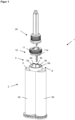
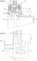
- the application system 1 comprises a cartridge 2 with a first container 2a and a second container 2b. Both containers 2a, 2b can be filled with a material to be stored and are regularly closed off on their side opposite the outlet area 3 of the cartridge 2 by a closure and/or dispensing piston (not shown).
- the outlet area 3 comprises the outlets 3a and 3b assigned to the containers 2a and 2b, which are in flow connection with the containers 2a and 2b via the outlet opening 4a or 4b.
- the axial length L of the outlets 3a and 3b measured from the end face 5 of the cartridge is, for example, 11.3 mm ⁇ 1 mm. From the ends of the outlets 3a and 3b in the material discharge direction to the outlet openings 4a and 4b of the containers 2a and 2b, the axial length is, for example, 11.5 mm ⁇ 1 mm.
- the outlet openings 4a, 4b open into the outlets 3a and 3b of the cartridge 2.
- the outlets 3a and 3b extend in the material discharge direction from the end face 5 of the cartridge 2.
- the end of the outlets 3a and 3b in the material discharge direction can be compared to the inner diameter of the outlet openings 4a and 4b have an increased inner diameter, e.g. increased by 10% compared to the inner diameter of that of the outlet openings 4a and 4b.
- the outlet openings 4a and 4b can each have an inner diameter of 4 mm ⁇ 0.1 mm, while the distal end of the outlets 3a and 3b has an inner diameter of 4.3 mm ⁇ 0.1 mm.
- annular connection area 6 is provided on the end face 5, which here includes an internal thread 6a for connection to the accessory.
- a first accessory here a stopper 10 connected.
- the sealing plug 10 comprises a cap nut 11 with an external thread 11a designed to match the internal thread 6a of the connection area 6 of the cartridge 2 .
- an insert 12 which is accommodated in the union nut 11 and has two locking pins 12a and 12b which can be inserted into the respective outlets 3a and 3b.
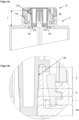
- the outer contour of the closure pins 12a and 12b is adapted to the inner contour of the respective outlets 3a and 3b in such a way that they achieve a seal between the outlet 3 and the closure plug 10 via a first sealing plane 7 .
- the outer contour of the locking pins 12a and 12b of the first accessory 10 is selected in such a way that there is an annular gap 13a, 13b between the locking pins 12a, 12b and the outlets 3a, 3b along the second sealing plane 8 is formed.
- annular gap 13a is provided around the locking pin 12a and a second annular gap 13b is provided around the second locking pin 12b.
- the annular gaps 13a, 13b prevent contact between the outlets 3a and 3b and the locking pins 12a, 12b in the area that is responsible for the formation of the second sealing level 8 and are dimensioned in particular in such a way that production-related fluctuations in the manufacture of the cartridge 2 or the first accessory 10 does not lead to the formation of a contact surface in the area of the second sealing plane 8.
- a seal-free section 9 is formed between the first sealing level 7 and the second sealing level 8 .
- this extends in the axial direction over 1.91 mm ⁇ 0.1 mm of the outlets 3a and 3b.
- second seal-free section 9a In the opposite direction to the material discharge direction, viewed from the first sealing plane 7, there is a second seal-free section 9a, which extends up to the outlet openings 4a and 4b.
- This second seal-free section 9a is on a radial plane with the end face 5 of the cartridge 2 at its end opposite to the material discharge direction.
- the axial length of the locking pins 12a and 12b is such that they reach the outlet openings 4a and 4b, so that no or at most a small amount of the material stored in the containers 2a and 2b can penetrate into the outlets 3a and 3b.
- the sealing pins 12a and 12b extend over 13.5 mm ⁇ 1 mm in the axial direction from the upper side lying in the material discharge direction to the underside lying opposite to the material discharge direction of the sealing plug 10 .
- first sealing level 7 is located in front of the second sealing level 8 in the material discharge direction, viewed from the end face 5 of the cartridge 2, since the material from the containers 2a, 2b can flow at best up to the first sealing level 7 . This prevents the second sealing level 8 from getting dirty during storage.
- the second seal-free section 9a allows the sealing plug 10 to be connected to the cartridge 2 and the outlet area 3 and to be detached from it with relatively little effort.
- This can be achieved, for example, in that the locking pins 12a and 12b have an outside diameter of 3.7 mm ⁇ 0.1 mm, which is 0.3 mm ⁇ 0.2 mm smaller than the inside diameter of the outlet openings 4a and 4b and the Outlets 3a and 3b in the area of the second seal-free section 9a.
- both the first sealing plane 7 and the second sealing plane 8 are spaced apart from the end face 5 of the cartridge 2 in the material discharge direction.
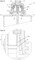
- an application system 1 with a second accessory here a static mixer 20
- the mixer 20 has a housing 21 with an external thread 21a designed to match the internal thread 6a of the connection area 6 .
- Inside the housing 21 is a Mixing area with a static mixing element 22 is provided. According to the invention, however, dynamic mixers can also be used.
- the second accessory has an inlet area 23 which is also accommodated within the housing 21 .
- the inlet region 23 has inlets 23a and 23b which are designed to correspond to the outlets 3a and 3b and which here are designed so that they can be inserted into the outlets 3a and 3b.
- a second sealing plane 8 is formed in this area.
- the inner diameter of the outlets 3a and 3b and the outer diameter of the inlets 23a and 23b can each be 4.3 mm ⁇ 0.1 mm.
- the inner contours of the inlets 23a and 23b are aligned with the outlet openings 4a and 4b of the respective containers 2a and 2b.
- the inner diameter of the inlets 23a and 23b and the inner diameter of the outlet ports 4a and 4b are each 4 mm ⁇ 0.1 mm.
- the alignment of the inlets 23a and 23b with the outlet openings 4a and 4b can also be achieved in the embodiment shown because the inner contour of the outlets 3a and 3b is larger in the area of the second sealing level 8 than in the area of the first sealing level 7 and the seal-free sections 9 and 9a. Therefore, the inner diameter of the outlets 3a and 3b increases as viewed in the material discharge direction.
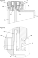
- the second embodiment which in the Figures 4a to 5b is shown shows an embodiment of the application system 1 according to the invention, in which the volumes of the containers 2a and 2b are different.
- the container 2a is smaller than the container 2b.
- the size of the corresponding outlet openings 4a and 4b is also adapted to the ratio of the volumes of containers 2a and 2b.
Landscapes
- Engineering & Computer Science (AREA)
- Mechanical Engineering (AREA)
- Containers And Packaging Bodies Having A Special Means To Remove Contents (AREA)
- Coating Apparatus (AREA)
Claims (9)
- Système d'application (1), pourvu d'une cartouche (2), d'au moins une première pièce accessoire (10), par exemple d'un bouchon (10) de fermeture, et d'au moins une deuxième pièce accessoire (20), par exemple d'un mélangeur (20) statique ou dynamique, la cartouche (2) comportant au moins un réservoir (2a, 2b) doté d'un orifice de sortie (4a, 4b) et sur sa face frontale (5) au moins une sortie (3a, 3b) reliée avec le réservoir (2a, 2b) par l'intermédiaire de l'orifice de sortie (4a, 4b), l'au moins une sortie (3a, 3b) pouvant être reliée avec l'au moins une première pièce accessoire (10) et l'au moins une deuxième pièce accessoire (20), de sorte à assurer une étanchéité entre la sortie (3a, 3b) et la pièce accessoire (10, 20) concernée, caractérisé en ce que pour chaque pièce accessoire (10, 20), il est prévu au moins un plan d'étanchéité (7, 8) séparé sur un contour interne de l'au moins une sortie (3a, 3b) ou que pour chaque pièce accessoire (10, 20), il est prévu au moins un plan d'étanchéité (7, 8) séparé sur le contour externe de l'au moins une sortie (3a, 3b) et qu'à chaque pièce accessoire (10, 20) est associé au moins l'un des plans d'étanchéité (7, 8),si pour chaque pièce accessoire (10, 20), il est prévu au moins un plan d'étanchéité (7, 8) séparé sur un contour interne de l'au moins une sortie (3a, 3b), chaque pièce accessoire (10, 20) étant conçue pour être insérable en assurant l'étanchéité dans l'au moins une sortie (3a, 3b), etsi pour chaque pièce accessoire (10, 20), il est prévu au moins un plan d'étanchéité (7, 8) séparé sur un contour externe de l'au moins une sortie (3a, 3b), l'au moins une sortie (3a, 3b) étant conçue pour être insérable en assurant l'étanchéité dans chaque pièce accessoire (10, 20).
- Système d'application (1) selon la revendication 1, caractérisé en ce que l'étanchéité entre l'au moins une première pièce accessoire (10) et l'au moins une sortie (3a, 3b) est assurée par l'intermédiaire d'au moins un premier plan d'étanchéité (7) et en ce que l'étanchéité entre l'au moins une deuxième pièce accessoire (20) et la sortie (3a, 3b) est assurée par l'intermédiaire d'au moins un deuxième plan d'étanchéité (8).
- Système d'application (1) selon l'une quelconque des revendications précédentes, caractérisé en ce que dans la direction d'évacuation du produit, l'au moins un deuxième plan d'étanchéité (8) est placé derrière l'au moins un premier plan d'étanchéité (7).
- Système d'application (1) selon l'une quelconque des revendications précédentes, caractérisé en ce qu'entre la première pièce accessoire (10) et au moins un deuxième plan d'étanchéité (8), il subsiste une fente annulaire (13a, 13b) lorsque la première pièce accessoire (10) est reliée avec l'au moins une sortie (3a, 3b) et / ou en ce que le deuxième plan d'étanchéité (8) est libre de forme et de contact par rapport à la première pièce accessoire (10).
- Système d'application (1) selon l'une quelconque des revendications précédentes, caractérisé en ce qu'entre les plans d'étanchéité (7, 8) respectifs, il est prévu un segment (9) sans joint.
- Système d'application (1) selon l'une quelconque des revendications précédentes, caractérisé en ce que dans la direction d'évacuation du produit, l'au moins un premier plan d'étanchéité (7) est placé avec un écart par rapport à la face frontale (5) de la cartouche (2).
- Système d'application (1) selon l'une quelconque des revendications précédentes, caractérisé en ce que considéré dans la direction d'évacuation du produit à partir de la face frontale (5) de la cartouche, l'au moins un premier plan d'étanchéité (7) est conçu de l'ordre de 5 % à 50 %, de préférence de 10 à 40 % de la longueur axiale (L) de l'au moins une sortie (3a, 3b) et / ou en ce que considéré dans la direction d'évacuation du produit à partir de la face frontale (5) de la cartouche (2), l'au moins un deuxième plan d'étanchéité (8) est conçu de l'ordre de 51 % à 100 %, de préférence de 55 % à 100 % de la longueur axiale (L) de l'au moins une sortie (3a, 3b).
- Système d'application (1) selon la revendication 7, caractérisé en ce que l'on conçoit l'au moins un premier plan d'étanchéité (7) sur un premier contour interne de l'au moins une sortie (3a, 3b) et l'au moins un deuxième plan d'étanchéité sur un deuxième contour interne de l'au moins une sortie (3a, 3b).
- Système d'application (1) selon l'une quelconque des revendications précédentes, caractérisé en ce que la première et / ou la deuxième pièce accessoire (10, 20) comporte une entrée (12a, 12b, 23a, 23b) insérable de manière à assurer l'étanchéité dans l'au moins une sortie (3a, 3b), le contour interne de l'entrée (12a, 12b, 23a, 23b) étant aligné sur l'orifice de sortie du réservoir (2a, 2b) dans la direction d'évacuation du produit.
Applications Claiming Priority (2)
| Application Number | Priority Date | Filing Date | Title |
|---|---|---|---|
| DE102019101651.7A DE102019101651A1 (de) | 2019-01-23 | 2019-01-23 | Applikationssystem mit verbesserter Dichtung |
| PCT/EP2020/050225 WO2020151938A1 (fr) | 2019-01-23 | 2020-01-07 | Système d'application à étanchéité améliorée |
Publications (2)
| Publication Number | Publication Date |
|---|---|
| EP3774581A1 EP3774581A1 (fr) | 2021-02-17 |
| EP3774581B1 true EP3774581B1 (fr) | 2023-07-19 |
Family
ID=69159765
Family Applications (1)
| Application Number | Title | Priority Date | Filing Date |
|---|---|---|---|
| EP20700555.4A Active EP3774581B1 (fr) | 2019-01-23 | 2020-01-07 | Système d'application à étanchéité améliorée |
Country Status (4)
| Country | Link |
|---|---|
| US (1) | US11518601B2 (fr) |
| EP (1) | EP3774581B1 (fr) |
| DE (1) | DE102019101651A1 (fr) |
| WO (1) | WO2020151938A1 (fr) |
Family Cites Families (18)
| Publication number | Priority date | Publication date | Assignee | Title |
|---|---|---|---|---|
| DE3524038A1 (de) * | 1985-07-05 | 1987-01-08 | Klebchemie M G Becker Gmbh | Vorrichtung zum einbringen von verbindenden stoffen, wie leim oder dergleichen in duebelloecher |
| ES2164750T3 (es) | 1995-03-07 | 2002-03-01 | Wilhelm A Keller | Dispositivo de fijacion por bayoneta para sujetar un accesorio a un cartucho de componentes multiples o dispositivo distribuidor. |
| DE20106406U1 (de) | 2001-04-12 | 2002-08-22 | Sulzer Chemtech Ag Winterthur | Verschluß für eine Zweikomponenten-Kartusche |
| DE10258953A1 (de) * | 2002-12-16 | 2004-07-22 | S&C Polymer Silicon- und Composite-Spezialitäten GmbH | Abgabevorrichtung für fluide Substanzen |
| EP1440737A1 (fr) | 2003-01-24 | 2004-07-28 | Mixpac Systems AG | Appareil distributeur pour au moins deux composants |
| DE102005003563B4 (de) * | 2005-01-25 | 2012-01-26 | Klebchemie, M.G. Becker Gmbh & Co Kg | Dosierpresse |
| EP1998901B9 (fr) * | 2006-03-24 | 2010-09-01 | Medmix Systems AG | Dispositif de distribution avec accessoires pouvant être fixés de maniere amovible |
| RU2431591C2 (ru) | 2007-03-19 | 2011-10-20 | Зульцер Микспэк Аг | Распределительный узел, содержащий вспомогательные устройства, прикрепляемые с возможностью съема |
| JP5172185B2 (ja) * | 2007-03-22 | 2013-03-27 | 株式会社ジーシー | ミキシングチップ |
| DE102008041282B4 (de) * | 2008-08-15 | 2017-01-19 | Faber-Castell Ag | Stift mit Verschlusskappe |
| US8365958B2 (en) * | 2010-02-12 | 2013-02-05 | Phillip Phung-I Ho | Device for mixing and discharging plural materials |
| DE102010049378B4 (de) | 2010-10-26 | 2014-07-03 | Kettenbach Gmbh & Co. Kg | Kartuschenanordnung mit einer Doppelkartusche |
| EP2520360B1 (fr) * | 2011-05-02 | 2014-07-16 | Sulzer Mixpac AG | Mélangeur destiné à mélanger au moins deux composants pouvant s'écouler ainsi que dispositif de sortie |
| ES2663728T3 (es) | 2011-10-17 | 2018-04-16 | Sulzer Mixpac Ag | Cartucho, procedimiento para la fabricación de este, así como cartucho multicomponente |
| US10099838B2 (en) * | 2015-04-13 | 2018-10-16 | Nordson Corporation | Fluid cartridge system and method of using a fluid cartridge system |
| DE102015110442B4 (de) * | 2015-06-29 | 2018-10-18 | Kettenbach Gmbh & Co. Kg | Ausbringbehälter mit Applikator und durch ihn gehaltenen Verschluss, sowie Verfahren |
| DE102016104410A1 (de) * | 2016-03-10 | 2017-09-14 | Heraeus Medical Gmbh | Lagerungs- und Mischsystem für pastenförmige Zementkomponenten und Verfahren dafür |
| DE102016104950A1 (de) * | 2016-03-17 | 2017-09-21 | Heraeus Medical Gmbh | Lagerungs- und Mischsystem für pastenförmige Zementkomponenten und Verfahren dafür |
-
2019
- 2019-01-23 DE DE102019101651.7A patent/DE102019101651A1/de active Pending
-
2020
- 2020-01-07 EP EP20700555.4A patent/EP3774581B1/fr active Active
- 2020-01-07 WO PCT/EP2020/050225 patent/WO2020151938A1/fr unknown
- 2020-01-07 US US17/258,079 patent/US11518601B2/en active Active
Also Published As
| Publication number | Publication date |
|---|---|
| EP3774581A1 (fr) | 2021-02-17 |
| US20210229891A1 (en) | 2021-07-29 |
| WO2020151938A1 (fr) | 2020-07-30 |
| DE102019101651A1 (de) | 2020-07-23 |
| US11518601B2 (en) | 2022-12-06 |
Similar Documents
| Publication | Publication Date | Title |
|---|---|---|
| EP0157121B1 (fr) | Récipient pour distribuer des pâtes dentaires | |
| EP1500606B1 (fr) | Cartouche à plusieurs composants | |
| EP1852390B1 (fr) | Soupape de refoulement pour un conteneur, en particulier un conteneur-palette | |
| DE102006050909A1 (de) | Mehrkomponentenkartusche | |
| EP2794119B1 (fr) | Cartouche, procédé de fabrication de celle-ci, ainsi que cartouche à plusieurs composants | |
| EP2851596B1 (fr) | Élément de traversée murale pour une conduite de fluide et traversée murale | |
| EP2885087B1 (fr) | Dispositif de sortie | |
| DE10246086B4 (de) | Behälter | |
| DE202006014087U1 (de) | Vorrichtung zum Ausbringen und Anmischen von Mehrkomponentenmassen | |
| DE69909618T2 (de) | Mehrkammerbehälter | |
| WO2013026721A1 (fr) | Mélangeur et dispositif de distribution | |
| DE69823286T2 (de) | Einheit aus zwei Elementen, die unumkehrbar und frei zueinander drehbar zusammengebaut sind | |
| EP0675295B1 (fr) | Dispositif de fixation | |
| WO2007118613A1 (fr) | RéSERVOIR DE LIQUIDE | |
| EP3941851B1 (fr) | Système d'emballage et procédé pour préparations de produit à plusieurs composants | |
| EP3774581B1 (fr) | Système d'application à étanchéité améliorée | |
| DE2904290A1 (de) | Verschlussanordnung | |
| DE202006016528U1 (de) | Mehrkomponentenkartusche | |
| DE3829356A1 (de) | Selbstschliessender behaelter-verschluss | |
| DE10057515A1 (de) | Verschlusskappe für Zweikammerbehälter | |
| WO1995021099A1 (fr) | Dispositif de bouchage pour recipient contenant des produits coulants | |
| EP3826932B1 (fr) | Ensemble composé d'un récipient et d'un capuchon | |
| AT504751B1 (de) | Behälterset | |
| DE102010060671B4 (de) | Integrierter Radialer Zapfenverschluss für Mehrkomponentenkartuschen mit Mischer | |
| DE4429065A1 (de) | Kupplungsstück |
Legal Events
| Date | Code | Title | Description |
|---|---|---|---|
| STAA | Information on the status of an ep patent application or granted ep patent |
Free format text: STATUS: UNKNOWN |
|
| STAA | Information on the status of an ep patent application or granted ep patent |
Free format text: STATUS: THE INTERNATIONAL PUBLICATION HAS BEEN MADE |
|
| PUAI | Public reference made under article 153(3) epc to a published international application that has entered the european phase |
Free format text: ORIGINAL CODE: 0009012 |
|
| STAA | Information on the status of an ep patent application or granted ep patent |
Free format text: STATUS: REQUEST FOR EXAMINATION WAS MADE |
|
| 17P | Request for examination filed |
Effective date: 20200831 |
|
| AK | Designated contracting states |
Kind code of ref document: A1 Designated state(s): AL AT BE BG CH CY CZ DE DK EE ES FI FR GB GR HR HU IE IS IT LI LT LU LV MC MK MT NL NO PL PT RO RS SE SI SK SM TR |
|
| AX | Request for extension of the european patent |
Extension state: BA ME |
|
| STAA | Information on the status of an ep patent application or granted ep patent |
Free format text: STATUS: EXAMINATION IS IN PROGRESS |
|
| 17Q | First examination report despatched |
Effective date: 20211026 |
|
| DAV | Request for validation of the european patent (deleted) | ||
| DAX | Request for extension of the european patent (deleted) | ||
| RAP3 | Party data changed (applicant data changed or rights of an application transferred) |
Owner name: 3LMED GMBH |
|
| GRAP | Despatch of communication of intention to grant a patent |
Free format text: ORIGINAL CODE: EPIDOSNIGR1 |
|
| STAA | Information on the status of an ep patent application or granted ep patent |
Free format text: STATUS: GRANT OF PATENT IS INTENDED |
|
| INTG | Intention to grant announced |
Effective date: 20230329 |
|
| GRAS | Grant fee paid |
Free format text: ORIGINAL CODE: EPIDOSNIGR3 |
|
| GRAA | (expected) grant |
Free format text: ORIGINAL CODE: 0009210 |
|
| STAA | Information on the status of an ep patent application or granted ep patent |
Free format text: STATUS: THE PATENT HAS BEEN GRANTED |
|
| AK | Designated contracting states |
Kind code of ref document: B1 Designated state(s): AL AT BE BG CH CY CZ DE DK EE ES FI FR GB GR HR HU IE IS IT LI LT LU LV MC MK MT NL NO PL PT RO RS SE SI SK SM TR |
|
| REG | Reference to a national code |
Ref country code: GB Ref legal event code: FG4D Free format text: NOT ENGLISH |
|
| REG | Reference to a national code |
Ref country code: CH Ref legal event code: EP |
|
| P01 | Opt-out of the competence of the unified patent court (upc) registered |
Effective date: 20230628 |
|
| REG | Reference to a national code |
Ref country code: DE Ref legal event code: R096 Ref document number: 502020004241 Country of ref document: DE |
|
| REG | Reference to a national code |
Ref country code: IE Ref legal event code: FG4D Free format text: LANGUAGE OF EP DOCUMENT: GERMAN |
|
| REG | Reference to a national code |
Ref country code: LT Ref legal event code: MG9D |
|
| REG | Reference to a national code |
Ref country code: NL Ref legal event code: MP Effective date: 20230719 |
|
| PG25 | Lapsed in a contracting state [announced via postgrant information from national office to epo] |
Ref country code: NL Free format text: LAPSE BECAUSE OF FAILURE TO SUBMIT A TRANSLATION OF THE DESCRIPTION OR TO PAY THE FEE WITHIN THE PRESCRIBED TIME-LIMIT Effective date: 20230719 |
|
| PG25 | Lapsed in a contracting state [announced via postgrant information from national office to epo] |
Ref country code: GR Free format text: LAPSE BECAUSE OF FAILURE TO SUBMIT A TRANSLATION OF THE DESCRIPTION OR TO PAY THE FEE WITHIN THE PRESCRIBED TIME-LIMIT Effective date: 20231020 |
|
| PG25 | Lapsed in a contracting state [announced via postgrant information from national office to epo] |
Ref country code: IS Free format text: LAPSE BECAUSE OF FAILURE TO SUBMIT A TRANSLATION OF THE DESCRIPTION OR TO PAY THE FEE WITHIN THE PRESCRIBED TIME-LIMIT Effective date: 20231119 |
|
| PG25 | Lapsed in a contracting state [announced via postgrant information from national office to epo] |
Ref country code: SE Free format text: LAPSE BECAUSE OF FAILURE TO SUBMIT A TRANSLATION OF THE DESCRIPTION OR TO PAY THE FEE WITHIN THE PRESCRIBED TIME-LIMIT Effective date: 20230719 Ref country code: RS Free format text: LAPSE BECAUSE OF FAILURE TO SUBMIT A TRANSLATION OF THE DESCRIPTION OR TO PAY THE FEE WITHIN THE PRESCRIBED TIME-LIMIT Effective date: 20230719 Ref country code: PT Free format text: LAPSE BECAUSE OF FAILURE TO SUBMIT A TRANSLATION OF THE DESCRIPTION OR TO PAY THE FEE WITHIN THE PRESCRIBED TIME-LIMIT Effective date: 20231120 Ref country code: NO Free format text: LAPSE BECAUSE OF FAILURE TO SUBMIT A TRANSLATION OF THE DESCRIPTION OR TO PAY THE FEE WITHIN THE PRESCRIBED TIME-LIMIT Effective date: 20231019 Ref country code: LV Free format text: LAPSE BECAUSE OF FAILURE TO SUBMIT A TRANSLATION OF THE DESCRIPTION OR TO PAY THE FEE WITHIN THE PRESCRIBED TIME-LIMIT Effective date: 20230719 Ref country code: LT Free format text: LAPSE BECAUSE OF FAILURE TO SUBMIT A TRANSLATION OF THE DESCRIPTION OR TO PAY THE FEE WITHIN THE PRESCRIBED TIME-LIMIT Effective date: 20230719 Ref country code: IS Free format text: LAPSE BECAUSE OF FAILURE TO SUBMIT A TRANSLATION OF THE DESCRIPTION OR TO PAY THE FEE WITHIN THE PRESCRIBED TIME-LIMIT Effective date: 20231119 Ref country code: HR Free format text: LAPSE BECAUSE OF FAILURE TO SUBMIT A TRANSLATION OF THE DESCRIPTION OR TO PAY THE FEE WITHIN THE PRESCRIBED TIME-LIMIT Effective date: 20230719 Ref country code: GR Free format text: LAPSE BECAUSE OF FAILURE TO SUBMIT A TRANSLATION OF THE DESCRIPTION OR TO PAY THE FEE WITHIN THE PRESCRIBED TIME-LIMIT Effective date: 20231020 Ref country code: FI Free format text: LAPSE BECAUSE OF FAILURE TO SUBMIT A TRANSLATION OF THE DESCRIPTION OR TO PAY THE FEE WITHIN THE PRESCRIBED TIME-LIMIT Effective date: 20230719 |
|
| PG25 | Lapsed in a contracting state [announced via postgrant information from national office to epo] |
Ref country code: PL Free format text: LAPSE BECAUSE OF FAILURE TO SUBMIT A TRANSLATION OF THE DESCRIPTION OR TO PAY THE FEE WITHIN THE PRESCRIBED TIME-LIMIT Effective date: 20230719 |
|
| PG25 | Lapsed in a contracting state [announced via postgrant information from national office to epo] |
Ref country code: ES Free format text: LAPSE BECAUSE OF FAILURE TO SUBMIT A TRANSLATION OF THE DESCRIPTION OR TO PAY THE FEE WITHIN THE PRESCRIBED TIME-LIMIT Effective date: 20230719 |
|
| PG25 | Lapsed in a contracting state [announced via postgrant information from national office to epo] |
Ref country code: SM Free format text: LAPSE BECAUSE OF FAILURE TO SUBMIT A TRANSLATION OF THE DESCRIPTION OR TO PAY THE FEE WITHIN THE PRESCRIBED TIME-LIMIT Effective date: 20230719 Ref country code: RO Free format text: LAPSE BECAUSE OF FAILURE TO SUBMIT A TRANSLATION OF THE DESCRIPTION OR TO PAY THE FEE WITHIN THE PRESCRIBED TIME-LIMIT Effective date: 20230719 Ref country code: ES Free format text: LAPSE BECAUSE OF FAILURE TO SUBMIT A TRANSLATION OF THE DESCRIPTION OR TO PAY THE FEE WITHIN THE PRESCRIBED TIME-LIMIT Effective date: 20230719 Ref country code: EE Free format text: LAPSE BECAUSE OF FAILURE TO SUBMIT A TRANSLATION OF THE DESCRIPTION OR TO PAY THE FEE WITHIN THE PRESCRIBED TIME-LIMIT Effective date: 20230719 Ref country code: DK Free format text: LAPSE BECAUSE OF FAILURE TO SUBMIT A TRANSLATION OF THE DESCRIPTION OR TO PAY THE FEE WITHIN THE PRESCRIBED TIME-LIMIT Effective date: 20230719 Ref country code: CZ Free format text: LAPSE BECAUSE OF FAILURE TO SUBMIT A TRANSLATION OF THE DESCRIPTION OR TO PAY THE FEE WITHIN THE PRESCRIBED TIME-LIMIT Effective date: 20230719 Ref country code: SK Free format text: LAPSE BECAUSE OF FAILURE TO SUBMIT A TRANSLATION OF THE DESCRIPTION OR TO PAY THE FEE WITHIN THE PRESCRIBED TIME-LIMIT Effective date: 20230719 |
|
| PGFP | Annual fee paid to national office [announced via postgrant information from national office to epo] |
Ref country code: DE Payment date: 20240125 Year of fee payment: 5 |