EP3774557B1 - Unit and method for fragmenting a bagged solid mass - Google Patents
Unit and method for fragmenting a bagged solid mass Download PDFInfo
- Publication number
- EP3774557B1 EP3774557B1 EP19714805.9A EP19714805A EP3774557B1 EP 3774557 B1 EP3774557 B1 EP 3774557B1 EP 19714805 A EP19714805 A EP 19714805A EP 3774557 B1 EP3774557 B1 EP 3774557B1
- Authority
- EP
- European Patent Office
- Prior art keywords
- bag
- fragmentation
- cylinder
- pressing
- vertical
- Prior art date
- Legal status (The legal status is an assumption and is not a legal conclusion. Google has not performed a legal analysis and makes no representation as to the accuracy of the status listed.)
- Active
Links
Images


Classifications
-
- B—PERFORMING OPERATIONS; TRANSPORTING
- B02—CRUSHING, PULVERISING, OR DISINTEGRATING; PREPARATORY TREATMENT OF GRAIN FOR MILLING
- B02C—CRUSHING, PULVERISING, OR DISINTEGRATING IN GENERAL; MILLING GRAIN
- B02C1/00—Crushing or disintegrating by reciprocating members
- B02C1/005—Crushing or disintegrating by reciprocating members hydraulically or pneumatically operated
-
- B—PERFORMING OPERATIONS; TRANSPORTING
- B65—CONVEYING; PACKING; STORING; HANDLING THIN OR FILAMENTARY MATERIAL
- B65B—MACHINES, APPARATUS OR DEVICES FOR, OR METHODS OF, PACKAGING ARTICLES OR MATERIALS; UNPACKING
- B65B69/00—Unpacking of articles or materials, not otherwise provided for
- B65B69/0075—Emptying systems for flexible intermediate bulk containers [FIBC]
- B65B69/0091—Emptying systems for flexible intermediate bulk containers [FIBC] using frames whereby the container is bottom supported
-
- B—PERFORMING OPERATIONS; TRANSPORTING
- B01—PHYSICAL OR CHEMICAL PROCESSES OR APPARATUS IN GENERAL
- B01F—MIXING, e.g. DISSOLVING, EMULSIFYING OR DISPERSING
- B01F31/00—Mixers with shaking, oscillating, or vibrating mechanisms
- B01F31/55—Mixers with shaking, oscillating, or vibrating mechanisms the materials to be mixed being contained in a flexible bag submitted to periodical deformation
-
- B—PERFORMING OPERATIONS; TRANSPORTING
- B30—PRESSES
- B30B—PRESSES IN GENERAL
- B30B15/00—Details of, or accessories for, presses; Auxiliary measures in connection with pressing
- B30B15/06—Platens or press rams
- B30B15/062—Press plates
-
- B—PERFORMING OPERATIONS; TRANSPORTING
- B30—PRESSES
- B30B—PRESSES IN GENERAL
- B30B15/00—Details of, or accessories for, presses; Auxiliary measures in connection with pressing
- B30B15/14—Control arrangements for mechanically-driven presses
Definitions
- the subject of the present invention is a unit for fragmenting a solid mass formed from a powdery or compacted particulate material, packaged in a large-capacity flexible transport bag.
- the present invention also relates to a process for fragmenting a compact, bagged mass.
- the state of the art offers various solutions aimed at breaking up the compact mass to reduce it to fragments of sufficiently small sizes to be able to be evacuated by the flexible evacuation handle that the bag includes.
- the various solutions proposed proceed by mechanical actions of pressing the material, and this through the flexible walls of the bag.
- two opposing pressing elements are essentially used, capable of exerting local pressure on two opposite outer faces of the flexible bag. Under the effect of these opposing pressures and the penetrating movement of the pressing elements, cracks appear locally in the compacted mass.
- the repetition of this action on the bag carried out according to various heights and positions, results in fragmenting the mass formed by the powdery material.
- this mass reaches a degree of division or fragmentation sufficient to be able to flow freely, by gravity, out of the bag, by passing through the evacuation sleeve.
- the patent US 5,944,470 shows a fragmentation unit formed of a support structure to which is hinged, at a distance from the ground, a horizontal platform designed to receive a pallet for transporting a packaging bag of powdery materials. Pivoting of the platform allows the contents of the bag to be dumped into a transporter installed on the floor.
- the platform carries two opposing fragmentation systems, each equipped with an elongated pressing element, actuated by a linear displacement mechanism.
- the two elongated pressing elements are adjustable in position to act at different locations on the corresponding walls of the bag.
- This document also shows fragmentation systems with tilting blades, driven in upward pivoting during the action on the bag.
- Another disadvantage of the aforementioned fragmentation units resides in the obligation to raise the bag above the ground in order to fragment the mass contained therein.
- This way of operating poses several problems, in particular problems of safety, and of handling a mass at height.
- the bag to be processed must be confined in an enclosed space, so that if it is inadvertently pushed off the lifting table, it cannot fall to the ground and injure people nearby. .
- this unit must necessarily be equipped with removable barriers, safety, able to oppose the fall of the bag.
- the object of the present invention is to overcome the aforementioned drawbacks.
- the present invention relates to a fragmentation unit in which the bag, whose contained mass is to be fragmented, rests on a support placed on the ground during the fragmentation operations.
- the present invention also relates to a fragmentation unit of reduced size, however, capable of receiving large capacity bags.
- the present invention relates to a fragmentation unit designed capable of facilitating, during the fragmentation operation, the movement in the bag of the fragmented material.
- the depth of the rear sub-zone is less than the depth of the front sub-zone.
- the plane (BB') is spaced at most fifteen centimeters from the plane (AA').
- the fragmentation unit is essentially characterized in that the plane (BB') is located behind the front face of the bag when the latter is present in the reception region.
- the fragmentation unit is essentially characterized in that each pressing plate of the pressing assembly occupies only part of the width of the bag when said bag is present in the region of reception and that each presser plate completely covers the normal distance between the planes BB' and DD'.
- each pressure plate covers only 50% to 65% of the width of the bag.
- each pressure plate is rigidly fixed to a dedicated carrier carriage, mounted movable in translation on horizontal rails, fixed to a common forklift mounted movable in translation on two vertical rails fixed to the rear side of the frame, the said carrying carriages being operable in translation along their rails towards or away from each other by motor organs.
- front chamber of the cylinder that of the two chambers of the latter containing the rod and by rear chamber, the opposite chamber.
- rear chamber By working chamber, it is necessary to understand that of the two chambers which are supplied with pressurized fluid to move in the direction of the pressing of the bag, the piston-rod assembly and the associated pressure plate.
- each drive member for actuating the carriages moving towards or away from each other is formed by a hydraulic cylinder and the two hydraulic cylinders are mounted hydraulically in series, the rear chamber of the first cylinder being hydraulically connected by a pipe to the front chamber of the second cylinder, the value of the section of the rear chamber of the first cylinder being equal to the value of the section of the front chamber of the second cylinder reduced by the value of the section of the rod of this second jack.
- the fragmentation unit is equipped with a means of measuring the displacement of the presser plates along their rails, and with a hydraulic pressure threshold detector associated with the supply circuit of the working chamber of one of the two jacks, said measuring means and said detector being connected to a control and command unit and said detector being able to deliver a threshold crossing signal when the pre-established threshold value is crossed, the control and command unit, from the reception of said signal, during an initialization phase according to which the presser plates are brought into pressure against the bag, ensuring the creation of an origin point for the displacements pressing plates, the latter, during each bag pressing operation, being moved towards each other from the point of origin by a constant, pre-established value.
- the height relative to the ground of the presser plates is adjustable. In this way, the action of the presser plates is staged and can be applied to the entire height of the bag.
- the forklift fixed to the guide rails of the carriages carrying the presser plates, is actuated in translation along its rails by a motor assembly formed of a vertical cylinder and a transmission of movement deployed between the rod of the cylinder and the lift truck, said transmission being arranged in a muffle in order to multiply the amplitude of the movement of the rod of the cylinder, the cylinder being oriented so that its rod occupies a higher position and the transmission of movement being formed on the one hand, of a roller rotatably mounted in a clevis fixed to the upper end of the cylinder rod, and on the other hand, of a lifting chain partially wound on the roller and fixed by a from its two ends to the lift truck and from its other end to the rear side.
- the hydraulic circuit for supplying the ram comprises hydraulic booster means.
- the lifting assembly is formed on the one hand, of a jib mounted so as to be able to move in translation on guide tracks which comprise vertical guide rails and, on the other hand, a motor assembly fixed to the rear side of the chassis and acting on the stem to move the latter in height, the said motor assembly being formed of a hydraulic cylinder and a motion transmission deployed between the stem and the rear side of the chassis, said hydraulic cylinder being oriented so that its rod occupies an upper position and said motion transmission being arranged in a muffle to multiply the amplitude of the movement of the cylinder rod and being formed of a roller rotatably mounted in a yoke carried by the cylinder rod and by a lifting chain partially wound around the roller and fixed by one of its two ends to the stem and by its other end, to the rear side of the frame.
- the present invention also relates to a process for fragmenting a bagged mass using a fragmentation unit according to the invention, as defined by claim 11.
- Raising the bag and setting it down after each fragmentation cycle helps to stir the material by breaking up any clumps of columnar or banked material that may have formed in the bag.
- Steps a) to f) will be carried out at minus n times, n being equal to the number of sides of the bag.
- the method consists, immediately before each fragmentation cycle, in bringing the presser plates back to the upper part of the bag and in repeating the previous fragmentation cycles.
- the trays will be brought to the upper part of the bag and after pressing the four faces, lowered by the predetermined displacement step to reach the second height level.
- the fragmentation trays will always be brought to the high position of the bag and after pressing the four sides, lowered to be arranged according to the level of height immediately below, the operations of pressing the four sides and lowering the trays repeating until reaching the corresponding pitch level.
- the fragmentation process consists in slowing down the movement of the bag during its rotation.
- the braking of the rotational movement of the bag is effected by friction of the bag on the perforated support.
- the braking of the rotational movement of the bag is effected by friction of said bag against the presser plates.
- the method consists, before lifting the bag, in angularly displacing the spindle of the head by a quarter turn. Is thus obtained, during the lifting of the bag, a slow angular displacement of the bag which can be further slowed down by friction against the perforated support and/or against the presser plates.
- the value of the downward displacement pitch of the presser plates is less than the height of each plate.
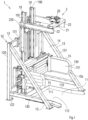
- a unit 1 for the fragmentation of a bagged solid mass, formed of a powdery or compacted granular material.
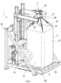
- This powdery or granular material is packaged in a flexible bag 5 of parallelepipedal shape, of large capacity, typically with a capacity of between 1.5 m 3 and 2 m 3 .
- the packaging bag 5 comprises a bottom 50, four vertical side walls 51, opposite in pairs, standing vertically on the bottom 50 and an upper wall 52 provided with a flexible sleeve 53 for filling.
- the bottom 50 of the bag is equipped with a flexible sleeve for emptying materials, not shown.
- the bag 5 has four lifting straps 55.
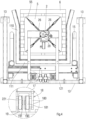
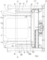
- the fragmentation unit 1 comprises a metal frame 10, comprising a vertical rear flank 12 and two lateral flanks 13 which are parallel and perpendicular to the rear flank 12. These rear and lateral flanks define an internal volume in which extends a reception region 11 of the bag 5 accessible by an access opening 14, formed in the front part of the frame 10, this opening 14 extending from one side flank 13 to the other.
- the region 11, of parallelepiped shape, is open upwards and is separated from the rear and lateral flanks.
- This region is delimited by the ground and by four flat vertical virtual faces, namely a front face 11a, a rear face 11b both parallel to the rear sidewall 12 and spaced apart from the latter, and two side faces 11c, both parallel to the sidewalls sides 13 of the chassis and separated from these said sidewalls 13.
- These virtual faces 11a, 11b and 11c are represented in strong dashed lines on the figure 5 . It should be noted that the two normal distances between the two pairs of opposite walls 51 of the bag 5 are respectively close to the normal distances between the virtual faces 11c and between the virtual faces 11a, 11b of the reception region 11.
- the rear side 12 of the frame 10 is formed by the assembly of two vertical uprights 120 to two upper 121 and lower 122 crosspieces.
- Each lateral flank 13 is fixed to one of the vertical uprights and is formed by a lower horizontal spar 130 and a strut 131.
- this strut 131 is fixed on the one hand, to the upright 120 corresponding to the rear side 12 and on the other hand, to the lower spar 130.
- This strut extends obliquely between said spar 130 and said upright 120.
- Region 11 is divided into a front zone 11d and a rear zone 11e of equal dimensions, by a vertical geometric plane AA' parallel to the rear side 12 of the frame 10.
- the front zone 11d faces the front opening 14 while that the rear zone 11e faces the rear flank 12.
- the two zones 11d, 11e have identical depths, this depth dimension being measured in a direction perpendicular to the rear flank 12.
- the region 11 at ground level is, preferably, equipped with lateral 110 and rear 111 abutment members defining an area 112 for receiving and wedging a perforated support 6, horizontal, provided to receive and transport the bag 5.
- the reception and wedging area 112 extends centrally with respect to the region 11.
- this area 112 extends symmetrically with respect to the plane AA' as well as symmetrical with respect to a plane CC' perpendicular to the plane AA' and located at equal distances from the two lateral sides 13 of the frame 10.
- the contour of the area 112 corresponds to the projection of the contour of the reception region 11 on a horizontal plane, this projection following a square contour and the area 112 constituting the horizontal background of the region 11.
- the lateral 110 and rear 111 abutment members are fixed to the ground by any known means, for example by lag bolts.
- each abutment member 110, 111 is formed by a section in the form of an angle iron comprising two wings perpendicular to each other, namely a horizontal wing for support and fixing to the ground and a vertical wing forming the actual abutment.
- the two lateral abutment members extend perpendicular to the rear flank 12 while the rear abutment member 111 is parallel to said flank 12.
- the horizontal wing of each abutment member is external to the reception area and wedging 112.
- the front parts of the two lateral stops 111 form a flare to facilitate the introduction of the perforated support 6 into the reception and wedging area 112.
- the perforated support 6 of square contour, is formed of horizontal slats 60 resting on an appropriate base.
- the horizontal slats 60 are parallel and arranged at constant spacing from each other.
- the base is made up of a series of dice and a lower support plate on the ground.
- this perforated support 6 is formed by the upper plate of a removable handling pallet 60, made of wood, known per se, of standardized dimensions.
- the length of each side of the reception area 112 is equal to or slightly greater by a few millimeters than the length of each horizontal side of the pallet 60 so that this pallet can freely be introduced into the reception area 112 and be removed from it. withdrawn.
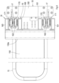
- the fragmentation unit 1 receives a functional pressing assembly comprising in particular two presser plates 15, metal, opposed, vertical, perpendicular to the rear side 12. These plates, of equal dimensions, are provided to come into pressure against two opposite sides of the bag 5 to fragment the contents. Preferably, they occupy with respect to the ground, the same level of height.
- These presser plates 15 can be driven simultaneously towards each other, towards the region 11 and consequently towards the bag 5, if the latter is present there to exert pressure there.
- the trays can also be driven simultaneously away from each other and from the region 11 and consequently from the bag 5, if the latter is present, to release the pressure and release said bag.
- Their height relative to the ground is adjustable so that the action of pressing and therefore of fragmentation is carried out over the entire height of the bag 5.
- each pressure plate 15 has a flat pressing face 150 by which it is brought into pressure against the bag 5, this flat face 150 being vertical, and perpendicular to the rear side 12 of the frame.
- this pressing face 150 has no discontinuity, that is to say no relief in hollow or recess.
- Each pressure plate 15 comprises a front edge 151 facing the front opening 14, an upper horizontal edge 152, a lower horizontal edge 153 and a rear edge 154.
- the pressing face 150 has a rear edge 150a that is preferably rectilinear, vertical, this rear edge 150a being opposite the front edge of the pressure plate 15 and being located in front of the rear edge 154 of said plate.
- the rear edge 150a of the pressing face 150 of each pressure plate 15 is located behind a geometric plane DD' containing the rear virtual face 11b and the length of each pressure plate 15 is such that the front edge 151 of said presser plate is tangent to a vertical geometric plane BB' parallel to plane AA' and dividing front zone 11d of region 11 into two front and rear sub-zones of unequal or equal depths.
- the depth of the rear sub-zone, that between the two planes AA' and BB' is less than the depth of the front sub-zone, i.e. that located between said plane BB' and the front virtual face 11a.
- depth is meant the normal distance between the planes AA' and BB' as regards the rear sub-zone and the normal distance between the plane BB' and the virtual front face 11a as regards the front sub-zone .
- each presser plate 15 only covers part of the width of the bag 5 when the latter is in place in the reception region 11, for example between 50 to 60% of said width while covering however the normal distance between the plane BB' and the DD' plan.
- the BB' plane is spaced at most fifteen centimeters from plane AA'.
- the bag 5 After each pressing cycle of two opposite faces, the bag 5 is pivoted a quarter turn to operate the pressing of the two other opposite faces.
- the bag is caused to complete a complete turn so that its four vertical faces are subjected to the action of the presser plates 15 and this along their entire width.
- each pressing plate 15 is rounded at its junction with the upper 152 and lower 153 horizontal edges to eliminate the risk of damaging the bag during pressing. This characteristic is reinforced by the fact that the pressure plate 15 has rounded edges.
- each pressure plate 15 is formed of a frame 15a laterally covered by a flat vertical sheet 15b whose flat face opposite the frame 15a constitutes the pressing face 150.
- This flat sheet is preferably solid in the sense that it is free of perforations.
- the framework 15a is advantageously formed of a frame made from hollow tubular sections, of circular cross sections.
- this framework is formed by an upper horizontal profiled element, of circular cross section, constituting the upper edge of the plate 15, by a lower horizontal profiled element, of circular cross section, constituting the lower edge of the plate 15, of an element rear vertical profile constituting the rear edge of the plate and a front vertical profile element, of circular cross section, constituting the front edge of the presser plate 15.
- the rear edge 154 of each presser plate 15 is located close to the rear side 12 to be moved away from the bag 5 when the latter is correctly positioned in the reception region 11.
- the frame constituting the frame 15a of the plate comprises one or more longitudinal struts, reinforcement, opposing the deformation of the flat sheet 15b during the pressing of the bag.
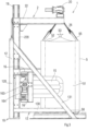
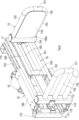
- Each presser plate 15, by the rear vertical profile, is rigidly fixed to a dedicated carrier carriage 16, mounted so as to move in horizontal translation along two horizontal rails 17, parallel, fixed to a common forklift 18 mounted from movable manner in vertical translation on two vertical rails 19 fixed to the rear side 12 of the chassis 1.
- the carrying carriages 16 and lift 18 as well as their guide rails 17 and 19 are integrated into the internal volume that defines the chassis 10 of the fragmentation unit and behind the region 11 for receiving the bag 5.
- the size of the fragmentation unit is thereby reduced.
- the carrying carriages 16 are actuated in horizontal translation along their rails 17 towards or away from each other by motor members 163, 164 integrated in the volume between the rear side 12 and the region 11 for receiving the bag 5.
- the two rails 17 are fixed to each other by two crosspieces 175, vertical, end.
- Each rail 17 has two horizontal, opposite guide tracks 170, 171, one of which cooperates in guiding with the carrier carriage 16 of one of the presser plates 15 and the other of which cooperates in guiding with the carrier carriage 16 of the another pressure plate 15.
- Each guide track 170, 171 comprises a horizontal basal flank and two lateral flanks, perpendicular to the basal flank.
- Each carriage 16 is formed of two horizontal, parallel, upper 160 and lower 161 beams, integrating guide rollers 162 subject to cooperating with the corresponding guide tracks 170 or 171. These beams 160, 161 are fixed by any known means to the profile vertical rear of the corresponding plate 15.
- each motor member 163, 164 consists of a hydraulic cylinder.
- the two hydraulic cylinders 163, 164 are preferably horizontal and parallel to the rear side 12 of the frame.
- These jacks are mounted oppositely and are fixed by their body, for example by a hinge, to the two end crosspieces 175.
- Each jack is fixed by its rod, for example by a hinge, to the carriage 16 which it actuates .
- These two cylinders 163, 164 are mounted hydraulically in series, in the sense that the rear chamber of the first cylinder 163 is connected by a pipe to the front chamber of the second cylinder 164.
- the value of the section of the rear chamber of the first cylinder 163 is equal to the value of the section of the front chamber of the second cylinder 164 reduced by the value of the section of the rod of this second cylinder, so that the useful sections of these two chambers are equal.
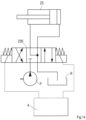
- the functional assembly formed by the two hydraulic cylinders 163, 164 is powered by a hydraulic circuit known per se, comprising in particular a hydraulic distributor 165.
- This distributor 165 is electrically controlled by a control and command unit 4 of a known type.
- the two pilots of the distributor are electrically connected by electrical connections, via an appropriate interface not shown, to the control and command unit 4.
- This distributor is for example of the four-orifice, three-position, four-way type. .
- FIG. 7 illustrates the hydraulic supply diagram for this hydraulic assembly. For reasons of simplification, all the hydraulic components are not represented on this diagram. In particular, flow limiters are not shown.
- one of the outlet ports of the distributor 165 is connected by a pipe to the rear chamber of the second jack 164 while the other outlet port is connected by a pipe to the front chamber of the first jack 163.
- this distributor 165 is connected by one of its two inlet orifices to a hydraulic pump P and by its other inlet orifice to an oil reservoir R.
- the carriages 16 are associated with a means of measuring their displacements along their rails 17.
- the hydraulic supply circuit of the hydraulic assembly formed by the two cylinders 163, 164 is associated with a hydraulic pressure threshold detector associated with the supply circuit of the working chamber of one of the two cylinders 163, 164
- the working chamber is the one which is supplied with pressurized fluid to move the pressing plates 15 towards each other and consequently, to move said plates 15 in the direction of pressing the bag. 5.
- the cylinders 163 and 164 during pressing, operate by pulling in the sense that during the pressing operation, their front chamber is supplied with fluid under pressure, by the pump P for what concerns the first cylinder 163 and by the rear chamber of this first cylinder 163 as regards the second cylinder 164.
- the displacement measuring means and the pressure threshold detector are electrically connected, by electrical connections via appropriate interfaces, to the control and command unit 4.
- the displacement measuring means is constituted by a cable position sensor, incorporating a drum for winding the cable and a sensitive element such as an encoder coupled to the drum and capable of delivering to the unit control and command 4, information representative of the cable unwinding value.
- a cable position sensor incorporating a drum for winding the cable and a sensitive element such as an encoder coupled to the drum and capable of delivering to the unit control and command 4, information representative of the cable unwinding value.
- a sensitive element such as an encoder coupled to the drum and capable of delivering to the unit control and command 4, information representative of the cable unwinding value.
- Such sensors are known from the state of the art and are in common use.
- the end of the cable can be fixed to one of the pressure plates 15 while the body of the sensor can be fixed to one of the rails 17.
- the pressure threshold detector is capable of delivering a signal representative of a pressure value greater than the threshold value in the corresponding hydraulic circuit. Thanks to this threshold detector, it is possible to perform, prior to any fragmentation operations, an initialization phase according to which a point of origin for the displacements of the presser plates 15 in the direction of their approximation, is established.
- This initialization phase is of course carried out after positioning the bag 5 in the region 11 of the fragmentation unit, and consists in bringing the presser plates 15 of the said bag 5 closer together until encountering a resistance to advancement representative of the contact of said trays 15 with said bag 5 ( Fig.10 ). This resistance to progress results in a sudden rise in pressure in the hydraulic circuit supplying the corresponding working chamber and in a crossing of the threshold value.
- a crossing signal is then emitted by the pressure threshold detector and is detected by the control and command unit 4 which can then, from the distance data delivered by the cable sensor, establish a point of origin for the movements trays 15.
- the trays 15 can then subsequently be moved towards each other from the point of origin over a limited pressing distance, of a predetermined value in view of the fragmentation of the mass of the bag ( Fig.11 ). Thus, the risk of damage to the bag will be eliminated.
- the plates 15 are arranged at mid-height of the bag 5, this zone usually being the most bulging. It should be noted that this initialization phase also makes it possible to determine the thickness of the bag, namely the distance between two opposite side walls 51 of said bag.
- the plates 15 are separated from each other and brought opposite the upper part of the bag 5. Subsequently, the fragmentation operation can begin. It consists in pressing each face of the bag by lowering the plates 15 after each pressing cycle by a predefined value, preferably less than the height of each pressing plate 15 in order to obtain a covering effect.
- the forklift 18 rigidly fixed to this assembly of pressing, is drivable in translation along the rails 19 by a motor assembly.
- the forklift 18 is fixed by any known means to the two guide rails 17 of the carriages 16 and is formed by two vertical uprights 180 carrying guide rollers 181. These guide rollers 181 cooperate in guiding with the two rails 19 As can be seen, these two rails 19 each have at least one guide track 190 comprising a basal flank and two lateral flanks perpendicular to the basal flank.
- the guide rollers 181 of one of the uprights 180 of the carriage are engaged in the guide track 190 of one of the two rails 19, the rollers 181 of the other upright 180 are engaged in the guide track of the another guide rail 19.
- the guide rollers 181 of each upright 180 are subject to rolling on the basal flank and on one of the two lateral flanks of the corresponding guide track 190.
- the functional pressing assembly is associated with a means for measuring its height relative to the ground and therefore for measuring its displacement.
- This measuring means may consist of a cable position sensor, of the type described above.
- This sensor will be connected by electrical connections and by an appropriate interface to the control and command unit 4.
- This sensor incorporates a cable winding drum and a sensitive element, such as an encoder, coupled to the drum.
- This sensor is capable of delivering to the control and command unit 4 information representative of the unwinding value of the cable and consequently of the height, relative to the ground, of the pressing assembly.
- the end of the cable can be fixed for example to one of the rails 17 of the functional pressing assembly, while the body of the sensor can be fixed to one of the rails 19.
- the drive motor assembly in translation of the lift truck 18 and consequently of the pressing assembly is preferably constituted by at least one hydraulic cylinder 182 and by a motion transmission deployed between the rod of the cylinder 182 and the forklift 18.
- the hydraulic cylinder 182, by its body, is preferably fixed by an articulation to a horizontal crosspiece fixed to the two rails 19. This cylinder 182 extends vertically against the rear side 12 of the chassis and is oriented so that its stem occupies a superior position.
- the transmission of movement is arranged in a muffle in order to multiply the amplitude of the movement of the rod of the jack 182.
- This transmission is formed on the one hand, of a roller 183 rotatably mounted in a yoke fixed at the end upper part of the cylinder rod 182 and on the other hand, a lifting chain 184 wound partially on the roller 183 and fixed by one of its two ends to the carriage 18 and by its other end to the upper crosspiece 121 of the rear side 12.
- FIG 12 schematically shows the hydraulic circuit associated with the hydraulic cylinder 182.
- the cylinder 182 is controlled by a controlled distributor 182a, of the four-orifice, three-position, four-way type.
- the two pilots of this distributor are electrically connected by electrical connections, via an appropriate interface not shown, to the control and command unit 4.
- this unit 4 is able to control the distributor 182a and consequently, the movements of the cylinder rod 182.
- the distributor 182a is connected as known by an appropriate pipe to the hydraulic pump P and by another pipe to the hydraulic tank R.
- a balancing valve formed of a pressure relief valve 182b and a non-return valve 182c arranged in parallel.
- the non-return valve 182c allows the direct supply of the rear chamber of the cylinder and opposes its emptying which can only take place via the pressure limiter 182b.
- this pressure limiter 182b is connected to the supply line of the front chamber of the cylinder 182.
- this pressure limiter is controlled by the pressure prevailing in the supply line of the front chamber of the jack and can only be activated from a predetermined pressure threshold to allow the evacuation of the oil contained in the rear chamber of the jack 182.
- the retraction of the rod of the jack 182 in the jack body and consequently, the downward movement of the pressing assembly can only take place from a determined pressure threshold, greater than the value of the hydraulic pressure that alone generates the weight of the pressing assembly in the front chamber of cylinder 182.
- a determined pressure threshold greater than the value of the hydraulic pressure that alone generates the weight of the pressing assembly in the front chamber of cylinder 182.
- the pressure relief valve 182b that comprises the balancing valve has an anti-overpressure drain.
- this balancing valve further constitutes a safety device.
- the presser plates 15 are biased upwards which generates an upward movement of the forklift 18 and of the pressing assembly. It is then necessary to prevent the lifting chain 184 from slackening and the resulting slack from causing the pressing assembly to move downwards under the effect of its weight, during the movement of the presser plates 15 apart. This unwanted movement may result in damage to the bag by friction of the presser plates against the walls of the latter. It is therefore necessary to constantly maintain the lifting chain 184 in tension.
- the hydraulic supply circuit of cylinder 182 includes hydraulic boosting means, the purpose of which is to maintain a minimum pressure in the rear chamber of cylinder 182 in order to keep chain 184 taut and to compensate for the weight of the chain. pressing assembly and the carriage 18 without moving them along the rails 19.
- Such hydraulic force-feeding means are represented schematically in figure 12 .
- These hydraulic booster means are formed by a controlled valve 182d and a pressure limiter 182e.
- the piloted valve 182d is of the normally closed type and of the type comprising two orifices, two positions, one way.
- This valve 182d is connected on the one hand, upstream of the limiter 182b and of the valve 182c to the supply line of the rear chamber of the cylinder 182.
- the valve 182d is connected to the pressure limiter 182e, it -even connected, via an appropriate return line, to the hydraulic reservoir R.
- the pilot of the valve 182d is connected to the control and command unit 4 by an electrical connection.
- the valve 182d is controlled by the control and command unit 4.
- control and command unit 4 activates the distributor 182a in the direction of the supply of the rear chamber of the cylinder 182 and simultaneously activates the valve 182d in order to establish communication between the supply line of the rear chamber of the cylinder 182 and the pressure relief valve 182e.
- the pressure in the rear chamber of cylinder 182 is limited to what is strictly necessary for the displacement of the rod of the cylinder to tension the lifting chain 184, while remaining well below the pressure value from of which the action on the piston of the cylinder rod compensates for the weight of the pressing assembly and generates the movement of said assembly upwards.
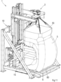
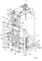
- the fragmentation unit 1 is further provided with a lifting assembly 2 designed to lift the bag and disengage it totally or partially from the perforated support 6 on which it rests.
- This lifting assembly 2 comprises, in accordance with the invention, a head 20 provided with a rotary spindle 21 arranged in line with the region 11 for receiving the bag, in a manner centered with respect to the latter, the vertical central geometric axis of said region and the geometric axis of rotation of spindle 21 being coincident. Attached to this pin 21 are slings 26 for attaching the carrying straps 55 of the bag 5.
- the straps 55 of the bag 5 converge at the center, that is to say towards the pin 21 and cannot , as a result, be subjected to mechanical tension during the pressing of the upper part of the bag.
- the lifting of the bag 5, during the fragmentation operations, contributes to the disintegration of the mass which it contains.
- the lifting assembly 2 comprises, on the one hand, a bracket 22 mounted so as to be able to move in translation on second guide tracks 191 that comprise the rails 19 and, on the other hand, a motor assembly fixed to the rear side 12 of the frame 10 and acting on the bracket 22 to move the latter in height.
- the head 20 is carried by the bracket 22 in line with the region 11 for receiving the bag 5.
- the bracket 22 carries the right of the region 11 for receiving the bag 5, the head 20.
- This bracket comprises two vertical uprights 220 equipped with guide rollers 221 provided to cooperate in guiding with the guide tracks 191.
- These guide tracks 191 are formed opposite to the tracks 190 and each comprise a basal flank and two lateral flanks perpendicular to the basal flank.
- the guide rollers 221 of each upright 220 are subject to rolling on the basal flank and on one of the lateral flanks of the corresponding guide track.
- the motor assembly provided for the movement of the stem 22 in height is formed by a hydraulic cylinder 23 and by a motion transmission deployed between the stem 22 and the rear side 12 of the frame 10.
- the cylinder 23 is powered by a hydraulic circuit, known per se, comprising in particular a hydraulic distributor 230, of the type for example four orifices, three positions, four ways.
- the two pilots of the distributor are connected by electrical connections, via an appropriate interface not shown, to the control and command unit 4.
- all the hydraulic components are not shown in figure 14 .
- the flow limiters are not shown.
- one of the outlet orifices of the distributor 230 is connected by a pipe to the rear chamber of the cylinder 23 while the other outlet orifice is connected by a pipe to the front chamber of this cylinder 23.
- this distributor 230 is connected by one of its two inlet ports to the hydraulic pump P and by its other inlet port, to the oil tank R.
- the motion transmission is arranged in a muffle to multiply the amplitude of the movement of the rod of the cylinder 23.
- the cylinder 23 is arranged vertically, the rod in the upper part, and the latter, in upper end carries a yoke in which is rotatably mounted a roller 24 around which is partially wound a lifting chain 25.
- This chain is fixed by one of its two ends to the bracket 22 and by its other end to the upper crosspiece 121 of the rear side 12.
- the chain 25 and the roller 24 constitute the transmission mentioned above.
- the head 20 of the lifting assembly incorporates a motor member consisting of a servo motor.
- This servomotor is connected by electrical connections to the control and command unit 4 in order to be controlled by the latter.
- This servo-motor is able to actuate in rotation about a vertical axis, the pin 21 of the head 20. It is understood that by lifting the bag, by moving the lifting assembly and rotating the pin 21 according to a quarter turn, two new opposite sides of the bag 5 will be brought opposite the presser plates 15.
- the lifting assembly is associated with a means of measuring its height relative to the ground.
- This measuring means may preferably consist of a cable position sensor, of the type of those previously described.
- This position sensor is connected by electrical connections, via an appropriate interface, to the control and command unit 4.
- the end of the cable can be fixed to the stem 22 while the body of this sensor can be fixed to one of the rails 19.
- the guide rollers 162, 181, and 221 are combined rollers. These rollers are each formed of a roller body in the form of a solid of revolution, receiving in rotation an outer ring constituting tread. The axis of rotation of this ring and the axis of revolution of the roller body coincide. By this outer ring, the roller is caused to roll on one of the side flanks of the corresponding guide track.
- the roller further comprises a second rolling member rotatably mounted on a shaft fixed to the roller body. The geometric axis of rotation of this second rolling member is perpendicular to the axis of rotation of the outer ring. This second rolling member is designed to roll on the basal side of the corresponding guide track.
- Such combined rollers as briefly described, are known from the state of the art and are in common use.
- fragmentation unit as described is intended to carry out the fragmentation operations before the bag emptying operations, it goes without saying that it can be used during this emptying to facilitate this operation, subject to the appropriate adaptations to the scope of those skilled in the art.
Landscapes
- Engineering & Computer Science (AREA)
- Mechanical Engineering (AREA)
- Chemical & Material Sciences (AREA)
- Chemical Kinetics & Catalysis (AREA)
- Food Science & Technology (AREA)
- Control And Other Processes For Unpacking Of Materials (AREA)
- Auxiliary Devices For And Details Of Packaging Control (AREA)
Description
La présente invention a pour objet une unité de fragmentation d'une masse solide formée d'un matériau pulvérulent ou particulaire compacté, conditionné dans un sac souple de transport de grande capacité. La présente invention a également pour objet un procédé de fragmentation d'une masse compacte, ensachée.The subject of the present invention is a unit for fragmenting a solid mass formed from a powdery or compacted particulate material, packaged in a large-capacity flexible transport bag. The present invention also relates to a process for fragmenting a compact, bagged mass.
On sait que certains matériaux pulvérulents ou particulaires destinés à alimenter des unités de production sont conditionnés dans des sacs souples de grande capacité. Généralement, la capacité de ces sacs est comprise entre 1 m3 et 2 m3. Habituellement, la capacité de ces sacs est de l'ordre de 1,5 m3.It is known that certain powdery or particulate materials intended to supply production units are packaged in large capacity flexible bags. Generally, the capacity of these bags is between 1 m 3 and 2 m 3 . Usually, the capacity of these bags is of the order of 1.5 m 3 .
On sait que de tels sacs souples présentent notamment quatre parois souples, verticales, surmontant un fond doté d'une manche souple d'évacuation des matériaux pulvérulents ou particulaires. On sait également que sous l'effet des vibrations mécaniques, le matériau pulvérulent contenu dans le sac est amené à se tasser sur lui-même et se transformer en une masse compacte. Un tel phénomène de tassement est bien souvent aussi le résultat d'un conditionnement à chaud des matériaux, suivi d'une forte baisse de température. Enfin, pour ce qui concerne les matériaux hygroscopiques, l'effet de tassement ou de compactage se trouve accentué par l'action de l'humidité de l'air. De ces différents effets, il résulte l'impossibilité de vider le sac par la manche souple d'évacuation.It is known that such flexible bags have in particular four flexible, vertical walls surmounting a bottom provided with a flexible sleeve for discharging powdery or particulate materials. It is also known that under the effect of mechanical vibrations, the pulverulent material contained in the bag is caused to settle on itself and transform into a compact mass. Such a compaction phenomenon is very often also the result of hot conditioning of the materials, followed by a sharp drop in temperature. Finally, as far as hygroscopic materials are concerned, the settling or compacting effect is accentuated by the action of air humidity. These different effects result in the impossibility of emptying the bag through the flexible evacuation sleeve.
Pour pallier cet inconvénient, l'état de la technique propose diverses solutions visant à fractionner la masse compacte pour la réduire en fragments de tailles suffisamment réduites pour pouvoir être évacués par manche souple d'évacuation que comporte le sac. Typiquement, les diverses solutions proposées procèdent par actions mécaniques de pressage du matériau, et ce au travers des parois souples du sac. À cet effet, sont essentiellement utilisés deux éléments presseurs opposés, aptes à exercer une pression locale sur deux faces externes opposées du sac souple. Sous l'effet de ces pressions opposées et du mouvement de pénétration des éléments presseurs, des fissures apparaissent localement dans la masse compactée. La répétition de cette action sur le sac, opérée selon diverses hauteurs et positions, conduit à fragmenter la masse que forme le matériau pulvérulent. Ainsi, cette masse atteint un degré de division ou de fragmentation suffisant pour pouvoir s'écouler librement, par gravité, hors du sac, par passage au travers de la manche d'évacuation.To overcome this drawback, the state of the art offers various solutions aimed at breaking up the compact mass to reduce it to fragments of sufficiently small sizes to be able to be evacuated by the flexible evacuation handle that the bag includes. Typically, the various solutions proposed proceed by mechanical actions of pressing the material, and this through the flexible walls of the bag. For this purpose, two opposing pressing elements are essentially used, capable of exerting local pressure on two opposite outer faces of the flexible bag. Under the effect of these opposing pressures and the penetrating movement of the pressing elements, cracks appear locally in the compacted mass. The repetition of this action on the bag, carried out according to various heights and positions, results in fragmenting the mass formed by the powdery material. Thus, this mass reaches a degree of division or fragmentation sufficient to be able to flow freely, by gravity, out of the bag, by passing through the evacuation sleeve.
Habituellement, la pression exercée sur le sac ainsi que la valeur de pénétration des éléments presseurs dans la masse compacte sont contrôlées afin que le sac ne soit pas endommagé et ne produise, du fait de cet endommagement, des débris de nature à polluer les matériaux pulvérulents. Des unités de fragmentation mettant en oeuvre les techniques sus-évoquées sont décrites notamment dans les documents
Le brevet
De tels systèmes de fragmentation à palettes basculantes sont également divulgués dans les brevets
Un des inconvénients des unités de fragmentation précitées réside dans la forme cylindrique des éléments presseurs. En effet, cette forme est de nature à créer un effet de poinçonnage risquant d'endommager le sac si l'effort de pressage est trop important. De plus, du fait que ces éléments presseurs présentent des surfaces de pressage relativement faibles, la masse contenue dans le sac, bien souvent n'est pas ramenée dans sa totalité à son état originel de sorte que subsistent dans le contenu du sac de nombreuses mottes, de tailles plus ou moins importantes qui d'une part, échappent à l'action de pressage et d'autre part, se trouvent repoussées vers le haut du sac.One of the drawbacks of the aforementioned fragmentation units resides in the cylindrical shape of the pressing elements. Indeed, this shape is likely to create a punching effect that risks damaging the bag if the pressing force is too great. In addition, because these pressing elements have relatively small pressing surfaces, the mass contained in the bag very often is not reduced in its entirety to its original state so that numerous clods of more or less large sizes remain in the contents of the bag which, on the one hand, escape the pressing action and, on the other hand, are pushed back to the top of the bag.
Un autre inconvénient des unités de fragmentations précitées, réside dans l'obligation d'élever le sac au-dessus du sol en vue d'en fragmenter la masse contenue. Cette façon d'opérer pose plusieurs problèmes, notamment des problèmes de sécurité, et de manutention d'une masse en hauteur. Pour sécuriser ces unités de fragmentation, le sac à traiter doit être confiné dans un espace clos, de façon que s'il est par mégarde poussé hors de la table élévatrice, il ne puisse chuter sur le sol et blesser les personnes se trouvant à proximité. Pour cette raison, cette unité doit nécessairement être équipée de barrières amovibles, de sécurité, aptes à s'opposer à la chute du sac. Ces dispositions augmentent les coûts de fabrication et de vente de l'unité de fragmentation.Another disadvantage of the aforementioned fragmentation units resides in the obligation to raise the bag above the ground in order to fragment the mass contained therein. This way of operating poses several problems, in particular problems of safety, and of handling a mass at height. To secure these fragmentation units, the bag to be processed must be confined in an enclosed space, so that if it is inadvertently pushed off the lifting table, it cannot fall to the ground and injure people nearby. . For this reason, this unit must necessarily be equipped with removable barriers, safety, able to oppose the fall of the bag. These arrangements increase the cost of manufacturing and selling the comminution unit.
La manutention d'une masse au-dessus du sol est effectuée à l'aide de chariots élévateurs dont la conduite est soumise à réglementation. Ainsi, le conducteur ou cariste doit avoir effectué une formation spécifique et doit être en possession d'un certificat d'aptitude à la conduite, périodiquement renouvelable. Ces différentes exigences, comme on le comprend, augmentent de manière significative le coût d'exploitation de l'unité de fragmentation.The handling of a mass above the ground is carried out using forklifts, the conduct of which is subject to regulations. Thus, the driver or forklift operator must have undergone specific training and must be in possession of a certificate of fitness to drive, periodically renewable. These different requirements, as is understood, significantly increase the operating cost of the comminution unit.
De tels inconvénients ne se retrouvent pas dans la demande
L'inconvénient d'une telle unité de fragmentation réside dans la longueur des plateaux qui couvre toute la largeur du sac (par longueur il faut entendre la plus grande dimension horizontale de ces derniers). Une telle disposition est de nature à limiter l'efficacité du pressage en freinant le déplacement dans le sac du matériau rendu à sa forme originelle. Or un tel déplacement, en permettant à ce matériau d'échapper à l'emprise des plateaux presseurs, s'avère nécessaire à l'obtention d'une fragmentation optimale de l'ensemble de la masse contenue dans le sac. En outre, les actionneurs des plateaux presseurs forment des saillies latérales, opposées, en débordement sur les flancs latéraux de l'unité de fragmentation. Une telle disposition accroît significativement l'encombrement latéral de l'unité de fragmentation et requiert un capotage adapté pour recouvrir les actionneurs.The disadvantage of such a fragmentation unit lies in the length of the plates which covers the entire width of the bag (by length is meant the greatest horizontal dimension of the latter). Such an arrangement is likely to limit the effectiveness of the pressing by slowing down the movement in the bag of the material returned to its original shape. However, such a displacement, by allowing this material to escape the grip of the pressure plates, proves necessary to obtain a fragmentation optimum of the whole of the mass contained in the bag. In addition, the actuators of the presser plates form lateral projections, opposite, overflowing on the lateral flanks of the fragmentation unit. Such an arrangement significantly increases the lateral bulk of the fragmentation unit and requires a cowling adapted to cover the actuators.
La demande de brevet
La présente invention a pour objet de pallier les inconvénients précités.The object of the present invention is to overcome the aforementioned drawbacks.
Ainsi la présente invention est relative à une unité de fragmentation dans laquelle le sac, dont la masse contenue est à fragmenter, repose sur un support posé au sol lors des opérations de fragmentation.Thus the present invention relates to a fragmentation unit in which the bag, whose contained mass is to be fragmented, rests on a support placed on the ground during the fragmentation operations.
La présente invention est également relative à une unité de fragmentation d'un encombrement réduit apte cependant à recevoir des sacs de grande capacité.The present invention also relates to a fragmentation unit of reduced size, however, capable of receiving large capacity bags.
Enfin la présente invention est relative à une unité de fragmentation conçue apte à faciliter, lors de l'opération de fragmentation, le déplacement dans le sac, du matériau fragmenté.Finally, the present invention relates to a fragmentation unit designed capable of facilitating, during the fragmentation operation, the movement in the bag of the fragmented material.
À cet effet, l'unité de fragmentation selon l'invention comporte :
- un châssis comprenant un flanc arrière vertical et deux flancs latéraux lesquels sont parallèles et perpendiculaires au flanc arrière, lesdits flancs définissant un volume interne dans lequel s'étend une région de réception d'un sac de forme parallélépipédique, dont le contenu est à fragmenter, ledit sac étant prévu pour reposer sur un support ajouré installé dans ladite région de réception, laquelle est accessible par une ouverture formée en partie avant du châssis, ladite région, de forme parallélépipédique, étant ouverte vers le haut, étant écartée des flancs arrière et latéraux du châssis, et étant délimitée par le sol et par quatre faces virtuelles, planes, verticales, à savoir une face virtuelle avant, une face virtuelle arrière, toutes deux parallèles au flanc arrière du châssis et deux faces virtuelles latérales, ladite région étant divisée en une zone avant et en une zone arrière d'égales dimensions par un plan géométrique vertical (AA') parallèle au flanc arrière du châssis,
- un ensemble de pressage comportant au moins deux plateaux presseurs verticaux, opposés, parallèles aux flancs latéraux du châssis montés dans le volume interne que définit le châssis, chaque plateau présentant une hauteur, une longueur définie selon une direction perpendiculaire au flanc arrière et s'étendant entre un bord arrière du plateau et un bord avant dudit plateau, opposé au dit bord arrière, ledit bord avant faisant face à l'ouverture avant, chaque plateau presseur présentant une face de pressage plane verticale, présentant un bord arrière opposé au bord avant du plateau presseur et lesdits plateaux presseurs étant montés de manière mobile en rapprochement ou éloignement l'un de l'autre et de manière mobile en hauteur,
et ladite unité de fragmentation se caractérise essentiellement en ce que : - le bord arrière de la face de pressage de chaque plateau presseur est situé en arrière d'un plan géométrique (DD') contenant ladite face arrière virtuelle plane, et que le bord avant de chaque plateau presseur est tangent à un plan géométrique vertical (BB') parallèle au plan (AA') et divisant ladite zone avant de la région en deux sous-zones, à savoir une sous-zone arrière comprise entre les plans (AA') et (BB') et une sous-zone avant, comprise entre le plan (BB') et la face avant virtuelle (11a) de ladite région,
- elle est pourvue d'un ensemble de levage prévu pour soulever le sac et le dégager du support ajouré sur lequel il repose, ledit ensemble de levage comportant une tête pourvue d'une broche rotative, prévue pour recevoir en fixation des sangles de transport du sac par l'entremise d'élingues, ladite broche étant actionnable en rotation par un organe moteur, afin d'entraîner le sac en pivotement selon un quart de tour, les dites sangles convergeant au centre, c'est-à-dire vers la broche, et ladite broche rotative étant disposée au droit de la région de réception du sac, de manière centrée par rapport à cette dernière, l'axe géométrique central vertical de ladite région et l'axe géométrique de rotation de la broche étant confondus.
- a frame comprising a vertical rear flank and two lateral flanks which are parallel and perpendicular to the rear flank, the said flanks defining an internal volume in which extends a region for receiving a bag of parallelepiped shape, the content of which is to be fragmented, said bag being provided to rest on a perforated support installed in said reception region, which is accessible by an opening formed in the front part of the frame, said region, of parallelepiped shape, being open upwards, being separated from the rear and lateral sides of the chassis, and being delimited by the ground and by four virtual, flat, vertical faces, namely a front virtual face, a rear virtual face, both parallel to the rear side of the chassis and two lateral virtual faces, said region being divided into a front zone and a rear zone of equal dimensions by a vertical geometric plane (AA') parallel to the rear side of the chassis,
- a pressing assembly comprising at least two vertical pressing plates, opposite, parallel to the side flanks of the frame mounted in the internal volume defined by the frame, each plate having a height, a length defined in a direction perpendicular to the rear flank and extending between a rear edge of the plate and a front edge of said plate , opposite said rear edge, said front edge facing the front opening, each presser plate having a flat vertical pressing face, having a rear edge opposite the front edge of the presser plate and said presser plates being movably mounted in approach or distance from each other and in a mobile way in height,
and said fragmentation unit is essentially characterized in that: - the rear edge of the pressing face of each pressure plate is located behind a geometric plane (DD') containing said flat virtual rear face, and that the front edge of each pressure plate is tangent to a vertical geometric plane (BB ') parallel to the plane (AA') and dividing said front zone of the region into two sub-zones, namely a rear sub-zone between the planes (AA') and (BB') and a front sub-zone, between the plane (BB') and the virtual front face (11a) of said region,
- it is provided with a lifting assembly provided for lifting the bag and disengaging it from the perforated support on which it rests, said lifting assembly comprising a head provided with a rotating pin, provided for receiving the straps for transporting the bag by means of slings, said spindle being operable in rotation by a motor member, in order to drive the bag in pivoting according to a quarter turn, the said straps converging at the center, that is to say towards the spindle , and said rotary spindle being arranged in line with the bag-receiving region, centered with respect to the latter, the central vertical geometric axis of said region and the geometric axis of rotation of the spindle being coincident.
Selon une autre caractéristique de l'invention, la profondeur de la sous-zone arrière est inférieure à la profondeur de la sous-zone avant.According to another characteristic of the invention, the depth of the rear sub-zone is less than the depth of the front sub-zone.
Selon une autre caractéristique de l'invention, le plan (BB') est écarté au plus de quinze centimètres du plan (AA').According to another characteristic of the invention, the plane (BB') is spaced at most fifteen centimeters from the plane (AA').
Selon un autre aspect de l'invention, l'unité de fragmentation est essentiellement caractérisée en ce que le plan (BB') est situé en arrière de la face avant du sac lorsque ce dernier est présent dans la région de réception.According to another aspect of the invention, the fragmentation unit is essentially characterized in that the plane (BB') is located behind the front face of the bag when the latter is present in the reception region.
Selon un autre aspect de l'invention, l'unité de fragmentation est essentiellement caractérisée en ce que chaque plateau presseur de l'ensemble de pressage n'occupe qu'une partie de la largeur du sac lorsque ledit sac est présent dans la région de réception et que chaque plateau presseur couvre en totalité la distance normale entre les plans BB' et DD'.According to another aspect of the invention, the fragmentation unit is essentially characterized in that each pressing plate of the pressing assembly occupies only part of the width of the bag when said bag is present in the region of reception and that each presser plate completely covers the normal distance between the planes BB' and DD'.
Selon une autre caractéristique de l'invention, chaque plateau presseur ne couvre que 50 % à 65 % de la largeur du sac.According to another characteristic of the invention, each pressure plate covers only 50% to 65% of the width of the bag.
Grâce à ces différentes dispositions, la part de matériau déjà rendue à son état originel du fait du pressage, par exemple un état pulvérulent, sous l'effet de l'action des efforts exercés sur le matériau par les plateaux presseurs est chassée de l'emprise de ces derniers par déplacement vers l'avant du sac et vers le haut. En raison de ce mouvement de chasse, des blocs non encore fragmentés peuvent rejoindre l'espace libéré par le matériau chassé et peuvent être alors soumis à l'action des plateaux lors d'une nouvelle action de pressage. De même en raison de ce mouvement de chasse, des blocs non fragmentés situés dans le champ des actions mécaniques de pressage ne sont plus protégés par le matériau chassé et se retrouvent de ce fait, directement exposés à l'action de dislocation exercée par des plateaux presseurs. On comprend donc qu'une telle disposition améliore grandement l'efficacité de l'unité de fragmentation.Thanks to these various arrangements, the part of material already returned to its original state due to the pressing, for example a powdery state, under the effect of the action of the forces exerted on the material by the pressing plates is driven out of the influence of the latter by moving the bag forward and upwards. Due to this movement hunting, blocks not yet fragmented can join the space released by the driven material and can then be subjected to the action of the plates during a new pressing action. Similarly, due to this flushing movement, non-fragmented blocks located in the field of the mechanical pressing actions are no longer protected by the flushed material and therefore find themselves directly exposed to the dislocation action exerted by plates. pressers. It is therefore understood that such an arrangement greatly improves the efficiency of the fragmentation unit.
Selon une autre caractéristique de l'invention, chaque plateau presseur est fixé rigidement à un chariot porteur, dédié, monté mobile en translation sur des rails horizontaux, fixés à un chariot élévateur commun monté mobile en translation sur deux rails verticaux fixés au flanc arrière du châssis, les dits chariots porteurs étant actionnables en translation le long de leurs rails en rapprochement ou éloignement l'un de l'autre par des organes moteurs.According to another characteristic of the invention, each pressure plate is rigidly fixed to a dedicated carrier carriage, mounted movable in translation on horizontal rails, fixed to a common forklift mounted movable in translation on two vertical rails fixed to the rear side of the frame, the said carrying carriages being operable in translation along their rails towards or away from each other by motor organs.
Dans ce qui suit est désignée par chambre avant du vérin, celle des deux chambres de ce dernier contenant la tige et par chambre arrière, la chambre opposée. Par chambre de travail, il faut comprendre celle des deux chambres que l'on alimente en fluide sous pression pour déplacer dans le sens du pressage du sac, l'ensemble piston tige et le plateau presseur associé.In what follows is designated by front chamber of the cylinder, that of the two chambers of the latter containing the rod and by rear chamber, the opposite chamber. By working chamber, it is necessary to understand that of the two chambers which are supplied with pressurized fluid to move in the direction of the pressing of the bag, the piston-rod assembly and the associated pressure plate.
Selon une autre caractéristique de l'invention, chaque organe moteur d'actionnement des chariots en rapprochement ou éloignement l'un de l'autre est formé par un vérin hydraulique et les deux vérins hydrauliques sont montés hydrauliquement en série, la chambre arrière du premier vérin étant connectée hydrauliquement par une conduite à la chambre avant du second vérin, la valeur de la section de la chambre arrière du premier vérin étant égale à la valeur de la section de la chambre avant du second vérin diminuée de la valeur de la section de la tige de ce second vérin. De cette manière les mouvements des plateaux presseurs en rapprochement ou en éloignement l'un de l'autre s'effectuent à la même vitesse et sont parfaitement synchronisés.According to another characteristic of the invention, each drive member for actuating the carriages moving towards or away from each other is formed by a hydraulic cylinder and the two hydraulic cylinders are mounted hydraulically in series, the rear chamber of the first cylinder being hydraulically connected by a pipe to the front chamber of the second cylinder, the value of the section of the rear chamber of the first cylinder being equal to the value of the section of the front chamber of the second cylinder reduced by the value of the section of the rod of this second jack. In this way, the movements of the presser plates towards or away from each other take place at the same speed and are perfectly synchronized.
Selon une autre caractéristique de l'invention, l'unité de fragmentation est équipée d'un moyen de mesure du déplacement des plateaux presseurs le long de leurs rails, et d'un détecteur de seuil de pression hydraulique associé au circuit d'alimentation de la chambre de travail de l'un des deux vérins, ledit moyen de mesure et ledit détecteur étant connectés à une unité de contrôle et de commande et ledit détecteur étant apte à délivrer un signal de franchissement de seuil lorsque la valeur de seuil préétablie est franchie, l'unité de contrôle et de commande, à partir de la réception dudit signal, lors d'une phase d'initialisation selon laquelle les plateaux presseurs sont amenés en pression contre le sac, assurant la création d'un point origine aux déplacements des plateaux presseurs, ces derniers, lors de chaque opération de pressage du sac, étant déplacés l'un vers l'autre à partir du point origine d'une valeur constante, préétablie.According to another characteristic of the invention, the fragmentation unit is equipped with a means of measuring the displacement of the presser plates along their rails, and with a hydraulic pressure threshold detector associated with the supply circuit of the working chamber of one of the two jacks, said measuring means and said detector being connected to a control and command unit and said detector being able to deliver a threshold crossing signal when the pre-established threshold value is crossed, the control and command unit, from the reception of said signal, during an initialization phase according to which the presser plates are brought into pressure against the bag, ensuring the creation of an origin point for the displacements pressing plates, the latter, during each bag pressing operation, being moved towards each other from the point of origin by a constant, pre-established value.
Selon une autre caractéristique de l'invention, la hauteur par rapport au sol des plateaux presseurs est ajustable. De cette manière, l'action des plateaux presseurs est étagée et peut-être appliquée à toute la hauteur du sac.According to another characteristic of the invention, the height relative to the ground of the presser plates is adjustable. In this way, the action of the presser plates is staged and can be applied to the entire height of the bag.
Selon une autre caractéristique de l'invention, le chariot élévateur, fixé aux rails de guidage des chariots porteurs des plateaux presseurs, est actionné en translation le long de ses rails par un ensemble moteur formé d'un vérin vertical et d'une transmission de mouvement déployée entre la tige du vérin et le chariot élévateur, ladite transmission étant agencée en moufle afin de multiplier l'amplitude du mouvement de la tige du vérin, le vérin étant orienté en sorte que sa tige occupe une position supérieure et la transmission de mouvement étant formée d'une part, d'un galet monté à rotation dans une chape fixée à l'extrémité supérieure de la tige du vérin, et d'autre part, d'une chaîne de levage enroulée partiellement sur le galet et fixée par une de ses deux extrémités au chariot élévateur et par son autre extrémité au flanc arrière.According to another characteristic of the invention, the forklift, fixed to the guide rails of the carriages carrying the presser plates, is actuated in translation along its rails by a motor assembly formed of a vertical cylinder and a transmission of movement deployed between the rod of the cylinder and the lift truck, said transmission being arranged in a muffle in order to multiply the amplitude of the movement of the rod of the cylinder, the cylinder being oriented so that its rod occupies a higher position and the transmission of movement being formed on the one hand, of a roller rotatably mounted in a clevis fixed to the upper end of the cylinder rod, and on the other hand, of a lifting chain partially wound on the roller and fixed by a from its two ends to the lift truck and from its other end to the rear side.
Additionnellement, selon une autre caractéristique de l'invention, le circuit hydraulique d'alimentation du vérin comporte des moyens hydrauliques de gavage.Additionally, according to another characteristic of the invention, the hydraulic circuit for supplying the ram comprises hydraulic booster means.
Selon une autre caractéristique de l'invention, l'ensemble de levage est formé d'une part, d'une potence montée de manière mobile en translation sur des pistes de guidage que comportent des rails verticaux de guidage et, d'autre part, d'un ensemble moteur fixé au flanc arrière du châssis et agissant sur la potence pour déplacer cette dernière en hauteur, le dit ensemble moteur étant formé d'un vérin hydraulique et d'une transmission de mouvement déployée entre la potence et le flanc arrière du châssis, ledit vérin hydraulique étant orienté en sorte que sa tige occupe une position supérieure et ladite transmission de mouvement étant agencée en moufle pour multiplier l'amplitude du mouvement de la tige du vérin et étant formée d'un galet monté à rotation dans une chape portée par la tige du vérin et par une chaîne de levage enroulée partiellement autour du galet et fixée par une de ses deux extrémités à la potence et par son autre extrémité, au flanc arrière du châssis. Par soulèvement du sac et rotation de la broche de la tête support selon une fraction de tour, par exemple selon un quart de tour, deux autres faces opposées du sac sont amenées en regard des plateaux presseurs.According to another characteristic of the invention, the lifting assembly is formed on the one hand, of a jib mounted so as to be able to move in translation on guide tracks which comprise vertical guide rails and, on the other hand, a motor assembly fixed to the rear side of the chassis and acting on the stem to move the latter in height, the said motor assembly being formed of a hydraulic cylinder and a motion transmission deployed between the stem and the rear side of the chassis, said hydraulic cylinder being oriented so that its rod occupies an upper position and said motion transmission being arranged in a muffle to multiply the amplitude of the movement of the cylinder rod and being formed of a roller rotatably mounted in a yoke carried by the cylinder rod and by a lifting chain partially wound around the roller and fixed by one of its two ends to the stem and by its other end, to the rear side of the frame. By lifting the bag and rotating the spindle of the support head through a fraction of a turn, for example through a quarter turn, two other opposite faces of the bag are brought opposite the presser plates.
La présente invention est également relative à un procédé de fragmentation d'une masse ensachée mettant en oeuvre une unité de fragmentation selon l'invention, tel que défini par la revendication 11.The present invention also relates to a process for fragmenting a bagged mass using a fragmentation unit according to the invention, as defined by
Ce procédé de fragmentation se caractérise essentiellement en ce qu'il consiste :
- I) à disposer les plateaux presseurs à mi-hauteur du sac et à les rapprocher l'un de l'autre jusqu'au contact avec le sac et établir un point origine aux déplacements des plateaux presseurs l'un vers l'autre,
- II) à amener les plateaux presseurs en partie supérieure du sac en vue de débuter un cycle de fragmentation,
- III) à débuter un cycle de fragmentation par pressage du sac,
- IV) après le cycle de fragmentation par pressage, à abaisser les plateaux presseurs d'un pas prédéfini de déplacement vers le bas,
- V) à répéter les étapes III et IV jusqu'à atteindre la zone inférieure du sac.
- I) to arrange the presser plates at mid-height of the bag and bring them closer to each other until they come into contact with the bag and establish a point of origin for the movements of the presser plates towards each other,
- II) to bring the pressing plates to the upper part of the bag in order to start a fragmentation cycle,
- III) to start a fragmentation cycle by pressing the bag,
- IV) after the crushing cycle by pressing, in lowering the presser plates by a predefined step of downward displacement,
- V) repeating steps III and IV until reaching the bottom area of the bag.
Selon une autre caractéristique du procédé selon l'invention, chaque cycle de fragmentation consiste :
- a) à appliquer les plateaux presseurs contre le sac et les déplacer l'un vers l'autre selon une distance prédéterminée, mesurée à partir du point origine, afin d'en fragmenter la masse contenue,
- b) à relâcher la pression,
- c) à écarter les plateaux presseurs l'un de l'autre,
- d) à soulever le sac,
- e) à faire pivoter le sac d'un quart de tour,
- f) à le reposer sur son support ajouré,
- g) à répéter les étapes a à f pour chacune des faces latérales du sac.
- a) applying the presser plates against the bag and moving them towards each other over a predetermined distance, measured from the point of origin, in order to fragment the mass contained therein,
- b) release the pressure,
- c) moving the presser plates away from each other,
- d) lifting the bag,
- e) to rotate the bag a quarter turn,
- f) to rest it on its perforated support,
- g) repeating steps a to f for each of the side faces of the bag.
Le fait d'élever le sac et le reposer après chaque cycle de fragmentation contribue à brasser le matériau en disloquant les amas de matériau sous forme de colonne ou de talus qui pourraient s'être formés dans le sac. Les étapes a) à f) seront effectuées au moins n fois, n étant égal au nombre de face du sac.Raising the bag and setting it down after each fragmentation cycle helps to stir the material by breaking up any clumps of columnar or banked material that may have formed in the bag. Steps a) to f) will be carried out at minus n times, n being equal to the number of sides of the bag.
Selon une autre caractéristique de l'invention, le procédé consiste, immédiatement avant chaque cycle de fragmentation, à ramener les plateaux presseurs en partie supérieure du sac et à répéter les cycles de fragmentation précédents. Ainsi, pour le deuxième cycle de fragmentation, les plateaux seront amenés en partie supérieure du sac et après pressage des quatre faces, abaissés du pas de déplacement prédéterminé pour atteindre le deuxième niveau de hauteur. Pour chacun des cycles suivants, les plateaux de fragmentation seront toujours amenés en position haute du sac et après pressage des quatre faces, abaissés pour être disposés selon le niveau de hauteur immédiatement inférieur, les opérations de pressage des quatre faces et d'abaissement des plateaux se répétant jusqu'à atteindre le niveau de hauteur correspondant.According to another characteristic of the invention, the method consists, immediately before each fragmentation cycle, in bringing the presser plates back to the upper part of the bag and in repeating the previous fragmentation cycles. Thus, for the second fragmentation cycle, the trays will be brought to the upper part of the bag and after pressing the four faces, lowered by the predetermined displacement step to reach the second height level. For each of the following cycles, the fragmentation trays will always be brought to the high position of the bag and after pressing the four sides, lowered to be arranged according to the level of height immediately below, the operations of pressing the four sides and lowering the trays repeating until reaching the corresponding pitch level.
Selon une autre caractéristique, le procédé de fragmentation consiste à freiner le mouvement du sac au cours de sa rotation.According to another characteristic, the fragmentation process consists in slowing down the movement of the bag during its rotation.
De préférence, selon une caractéristique complémentaire, le freinage du mouvement de rotation du sac est opéré par frottement du sac sur le support ajouré.Preferably, according to an additional characteristic, the braking of the rotational movement of the bag is effected by friction of the bag on the perforated support.
Alternativement, le freinage du mouvement de rotation du sac est opéré par frottement dudit sac contre les plateaux presseurs.Alternatively, the braking of the rotational movement of the bag is effected by friction of said bag against the presser plates.
Selon une autre caractéristique, le procédé consiste, avant soulèvement du sac, à déplacer angulairement la broche de la tête d'un quart de tour. Est obtenu ainsi, lors du soulèvement du sac, un déplacement angulaire lent du sac qui peut être de plus freiné par frottement contre le support ajouré et/ou contre les plateaux presseurs.According to another characteristic, the method consists, before lifting the bag, in angularly displacing the spindle of the head by a quarter turn. Is thus obtained, during the lifting of the bag, a slow angular displacement of the bag which can be further slowed down by friction against the perforated support and/or against the presser plates.
Selon une autre caractéristique du procédé selon l'invention, la valeur du pas de déplacement vers le bas des plateaux presseurs est inférieure la hauteur de chaque plateau. Ainsi, d'un cycle à l'autre, un effet de recouvrement est obtenu.According to another characteristic of the method according to the invention, the value of the downward displacement pitch of the presser plates is less than the height of each plate. Thus, from one cycle to another, an overlapping effect is obtained.
D'autres buts, avantages et caractéristiques de l'invention apparaîtront à la lecture d'une forme préférée de réalisation, donnée à titre d'exemple non limitatif en se référant aux dessins annexés en lesquels :
- la
figure 1 est une vue en perspective d'une unité de fragmentation selon l'invention, le sac et le support ajouré de ce dernier n'étant pas représentés sur cette figure, - la
figure 2 est une vue en perspective d'une unité de fragmentation selon l'invention, équipée d'un sac dont le contenu est à fragmenter, - la
figure 3 est une vue de face de l'unité de fragmentation selon l'invention, - la
figure 4 est une vue de dessus de l'unité de fragmentation selon l'invention, - la
figure 5 est une vue de dessus de la région de réception du sac, - la
figure 6 est une vue en perspective de l'ensemble de pressage formé par les plateaux presseurs, leur vérin d'actionnement et leur chariot et rails de guidage, - la
figure 7 est une vue arrière de l'ensemble de pressage, - la
figure 8 est une vue en coupe selon la ligne EE de lafigure 7 , - la
figure 9 est une vue du schéma hydraulique d'alimentation des vérins d'actionnement des plateaux presseurs, - la
figure 10 montre en perspective l'unité de fragmentation lors d'une phase d'initialisation, - la
figure 11 montre en perspective l'unité de fragmentation en situation de fragmentation du contenu du sac, - la
figure 12 est un schéma hydraulique montrant notamment les moyens de gavage hydraulique de la chambre arrière du vérin de déplacement des plateaux de pressage en hauteur, - la
figure 13 montre, en perspective, l'unité de fragmentation en situation de levage du sac, - la
figure 14 est un schéma hydraulique simplifié montrant l'alimentation du vérin de l'ensemble de levage, - la
figure 15 est une vue arrière, en perspective, de l'unité de fragmentation.
- there
figure 1 is a perspective view of a fragmentation unit according to the invention, the bag and the perforated support of the latter not being shown in this figure, - there
figure 2 is a perspective view of a fragmentation unit according to the invention, equipped with a bag whose content is to be fragmented, - there
picture 3 is a front view of the fragmentation unit according to the invention, - there
figure 4 is a top view of the fragmentation unit according to the invention, - there
figure 5 is a top view of the bag receiving region, - there
figure 6 is a perspective view of the pressing assembly formed by the pressing plates, their actuating cylinder and their carriage and guide rails, - there
figure 7 is a rear view of the pressing assembly, - there
figure 8 is a sectional view along the line EE of thefigure 7 , - there
figure 9 is a view of the hydraulic supply diagram for the actuation cylinders of the presser plates, - there
figure 10 shows in perspective the fragmentation unit during an initialization phase, - there
figure 11 shows in perspective the fragmentation unit in a situation of fragmentation of the contents of the bag, - there
figure 12 is a hydraulic diagram showing in particular the means of hydraulic boosting of the rear chamber of the cylinder for moving the pressing plates in height, - there
figure 13 shows, in perspective, the fragmentation unit in a situation of lifting the bag, - there
figure 14 is a simplified hydraulic diagram showing the supply of the cylinder of the lifting assembly, - there
figure 15 is a rear perspective view of the fragmentation unit.
Sur les figures jointes est représentée une unité 1, selon l'invention, de fragmentation d'une masse solide ensachée, formée d'un matériau pulvérulent ou granulaire compacté. Ce matériau pulvérulent ou granulaire est conditionné dans un sac souple 5 de forme parallélépipédique, de grande capacité, typiquement d'une contenance comprise entre 1,5 m3 et 2 m3.In the attached figures is shown a
Le sac de conditionnement 5 comporte un fond 50, quatre parois latérales verticales 51, opposées deux à deux, dressées verticalement sur le fond 50 et une paroi supérieure 52 pourvue d'une manche souple 53 de remplissage. Le fond 50 du sac est équipé d'une manche souple de vidage des matériaux, non représentée. Enfin, le sac 5 comporte quatre sangles de levage 55.The
L'unité 1 de fragmentation comporte un châssis 10 en métal, comprenant un flanc arrière vertical 12 et deux flancs latéraux 13 lesquels sont parallèles et perpendiculaires au flanc arrière 12. Ces flancs arrière et latéraux définissent un volume interne dans lequel s'étend une région de réception 11 du sac 5 accessible par une ouverture 14 d'accès, formée en partie avant du châssis 10, cette ouverture 14 s'étendant d'un flanc latéral 13 à l'autre. La région 11, de forme parallélépipédique, est ouverte vers le haut et est écartée des flancs arrière et latéraux. Cette région est délimitée par le sol et par quatre faces virtuelles verticales planes, à savoir une face avant 11a, une face arrière 11b toutes deux parallèles au flanc arrière 12 et écartées de ce dernier, et deux faces latérales 11c, toutes deux parallèles aux flancs latéraux 13 du châssis et écartées de ces dits flanc 13. Ces faces virtuelles 11a, 11b et 1 1c sont représentées en traits mixtes forts sur la
Le flanc arrière 12 du châssis 10 est formé par l'assemblage de deux montants verticaux 120 à deux traverses supérieure 121 et inférieure 122.The
Chaque flanc latéral 13 est fixé à l'un des montants verticaux et est formé d'un longeron horizontal inférieur 130 et d'une jambe de force 131. Comme on peut le voir, cette jambe de force 131 est fixée d'une part, au montant 120 correspondant du flanc arrière 12 et d'autre part, au longeron inférieur 130. Cette jambe de force s'étend de manière oblique entre ledit longeron 130 et ledit montant 120.Each
La région 11 est divisée en une zone avant 11d et en une zone arrière 11e d'égales dimensions, par un plan géométrique vertical AA' parallèle au flanc arrière 12 du châssis 10. La zone avant 11d est tournée vers l'ouverture avant 14 tandis que la zone arrière 11e est tournée vers le flanc arrière 12. Ainsi, les deux zones 11d, 11e présentent des profondeurs identiques, cette dimension de profondeur étant mesurée selon une direction perpendiculaire au flanc arrière 12. La région 11 au niveau du sol est, de préférence, équipée d'organes de butée latéraux 110 et arrière 111 définissant une aire 112 de réception et de calage d'un support ajouré 6, horizontal, prévu pour recevoir et transporter le sac 5.
L'aire de réception et de calage 112, de préférence de forme carrée, s'étend de manière centrée par rapport à la région 11. Ainsi, cette aire 112 s'étend de manière symétrique par rapport au plan AA' ainsi que de manière symétrique par rapport à un plan CC' perpendiculaire au plan AA' et situé à égales distances des deux flancs latéraux 13 du châssis 10. On remarque que le contour de l'aire 112 correspond à la projection du contour de la région de réception 11 sur un plan horizontal, cette projection épousant un contour carré et l'aire 112 constituant le fond horizontal de la région 11.The reception and wedging
Les organes de butée latéraux 110 et arrière 111 sont fixés au sol par tout moyen connu, par exemple par des tirefonds.The lateral 110 and rear 111 abutment members are fixed to the ground by any known means, for example by lag bolts.
Selon une forme pratique de réalisation, chaque organe de butée 110, 111 est formé par un profilé sous forme de cornière comportant deux ailes perpendiculaires l'une à l'autre, à savoir une aile horizontale d'appui et de fixation au sol et une aile verticale formant la butée proprement dite. Les deux organes de butée latéraux s'étendent de manière perpendiculaire au flanc arrière 12 tandis que l'organe de butée arrière 111 est parallèle audit flanc 12. L'aile horizontale de chaque organe de butée est externe à l'aire de réception et de calage 112. Avantageusement, les parties avant des deux butées latérales 111 forment un évasement pour faciliter l'introduction du support ajouré 6 dans l'aire de réception et de calage 112.According to a practical embodiment, each
Le support ajouré 6, de contour carré, est formé de lattes horizontales 60 reposant sur un piètement approprié. Les lattes horizontales 60 sont parallèles et disposées à écartement constant les unes des autres. Le piètement est formé d'une série de dés et d'un plateau inférieur d'appui au sol. Avantageusement, ce support ajouré 6 est formé par le plateau supérieur d'une palette amovible de manutention 60, en bois, connue en soi, de dimensions normalisées. La longueur de chaque côté de l'aire de réception 112 est égale ou légèrement supérieure de quelques millimètres à la longueur de chaque côté horizontal de la palette 60 de façon que cette palette puisse librement être introduite dans l'aire de réception 112 et en être retirée.The
Il y a lieu de noter que l'introduction dans l'aire de réception 112 de la palette 60 et son retrait seront effectués à l'aide d'un engin de manutention à fourche du genre transpalette dont l'utilisation, pour le transport de charge, n'est pas soumise à autorisation administrative. Cet engin peut, de ce fait, être manoeuvré par un personnel sans formation spécifique.It should be noted that the introduction into the
Dans son volume interne, l'unité de fragmentation 1 reçoit un ensemble fonctionnel de pressage comprenant notamment deux plateaux presseurs 15, métalliques, opposés, verticaux, perpendiculaires au flanc arrière 12. Ces plateaux, d'égales dimensions, sont prévus pour venir en pression contre deux flancs opposés du sac 5 pour en fragmenter le contenu. De préférence, ils occupent par rapport au sol, un même niveau de hauteur. Ces plateaux presseurs 15 sont entraînables simultanément l'un vers l'autre, vers la région 11 et par voie de conséquence vers le sac 5, si ce dernier y est présent pour y exercer une pression. Les plateaux sont également entraînables simultanément en éloignement l'un de l'autre et de la région 11 et par conséquent du sac 5, si ce dernier est présent, pour relâcher la pression et libérer ledit sac. Leur hauteur par rapport au sol est ajustable afin que l'action de pressage et donc de fragmentation soit effectuée sur toute la hauteur du sac 5.In its internal volume, the
De préférence, chaque plateau presseur 15 présente une face plane 150 de pressage par laquelle il est amené en pression contre le sac 5, cette face plane 150 étant verticale, et perpendiculaire au flanc arrière 12 du châssis. De préférence, cette face de pressage 150 ne présente aucune discontinuité c'est-dire aucun relief en creux ou évidement.Preferably, each
Chaque plateau presseur 15 comprend un bord avant 151 faisant face à l'ouverture avant 14, un bord horizontal supérieur 152, un bord horizontal inférieur 153 et un bord arrière 154. La face de pressage150 présente un bord arrière 150a de préférence rectiligne, vertical, ce bord arrière 150a étant opposé au bord avant du plateau presseur 15 et étant situé en avant du bord arrière 154 dudit plateau.Each
Conformément à l'invention, le bord arrière 150a de la face de pressage 150 de chaque plateau presseur 15 est situé en arrière d'un plan géométrique DD' contenant la face virtuelle arrière 11b et la longueur de chaque plateau presseur 15 est telle que le bord avant 151 dudit plateau presseur est tangent à un plan géométrique BB' vertical parallèle au plan AA' et divisant la zone avant 11d de la région 11 en deux sous-zones avant et arrière d'inégales ou d'égales profondeurs. Préférentiellement, la profondeur de la sous-zone arrière, celle comprise entre les deux plans AA' et BB' est inférieure à la profondeur de la sous-zone avant c'est à dire celle située entre ledit plan BB' et la face virtuelle avant 11a. Par profondeur, il faut entendre la distance normale entre les plans AA' et BB' pour ce qui concerne la sous-zone arrière et la distance normale entre le plan BB' et la face avant virtuelle 11a pour ce qui concerne la sous-zone avant.According to the invention, the
Le plan BB', est donc situé en arrière et à écartement de la face virtuelle 11a et, lorsque le sac 5 est correctement en place dans la région de réception 11, est situé en arrière et à écartement de la face avant du dit sac 5. Ainsi chaque plateau presseur 15 ne couvre qu'une partie de la largeur du sac 5 lorsque ce dernier est en place dans la région de réception 11, par exemple entre 50 à 60% de ladite largeur en couvrant cependant la distance normale entre le plan BB' et le plan DD'. Préférentiellement, le plan BB' est écarté au plus de quinze centimètres du plan AA'. Ainsi, lors de chaque opération de pressage, la partie non pressée du sac située immédiatement en avant des plateaux presseurs 15 peut facilement accueillir le matériau chassé par l'action de pressage en étant libre de se déformer.The plane BB', is therefore located behind and away from the virtual face 11a and, when the
Après chaque cycle de pressage de deux faces opposées, le sac 5 est pivoté d'un quart de tour pour opérer le pressage des deux autres faces opposées. Ainsi, le sac est amené à accomplir un tour complet afin que ses quatre faces verticales soient soumises à l'action des plateaux presseurs 15 et ce suivant selon toute leur largeur. Le fait que les plateaux presseurs 15 couvrent un peu plus de la moitié de la largeur de chaque face du sac, permet d'obtenir lors du pressage, un effet de recouvrement.After each pressing cycle of two opposite faces, the
Préférentiellement, le bord avant 151 de chaque plateau presseur 15 est arrondi au niveau de sa jonction avec les bords horizontaux supérieur 152 et inférieur 153 pour écarter le risque d'endommagement du sac lors du pressage. Cette caractéristique se trouve renforcée par le fait que le plateau presseur 15 présente des tranches arrondies.Preferably, the
Selon une forme pratique de réalisation, chaque plateau presseur 15 est formé d'une ossature 15a recouverte latéralement par une tôle plane 15b verticale dont la face plane opposée à l'ossature 15a, constitue la face de pressage 150. Cette tôle plane est de préférence pleine en ce sens qu'elle est exempte de perforations. L'ossature 15a est avantageusement formée d'un cadre réalisé à partir de profilés tubulaires creux, de sections droites circulaires. Ainsi, cette ossature est formée par un élément profilé supérieur horizontal, de section droite circulaire, constituant le bord supérieur du plateau 15, par un élément profilé inférieur horizontal, de section droite circulaire, constituant le bord inférieur du plateau 15, d'un élément profilé vertical arrière constituant le bord arrière du plateau et d'un élément profilé vertical avant, de section droite circulaire, constituant le bord avant du plateau presseur 15. Il y a lieu de noter que le bord arrière 154 de chaque plateau presseur 15 se situe à proximité du flanc arrière 12 pour être écarté du sac 5 lorsque ce dernier est correctement positionné dans la région de réception 11.According to a practical embodiment, each
Avantageusement, le cadre constitutif de l'ossature 15a du plateau comporte une ou plusieurs entretoises longitudinales, de renfort, s'opposant à la déformation de la tôle plane 15b lors du pressage du sac.Advantageously, the frame constituting the
Chaque plateau presseur 15, par le profilé vertical arrière, est fixé rigidement à un chariot porteur 16 dédié, monté de manière mobile en translation horizontale le long de deux rails horizontaux 17, parallèles, fixés à un chariot élévateur commun 18 monté de manière mobile en translation verticale sur deux rails verticaux 19 fixés au flanc arrière 12 du châssis 1. Comme on peut le voir, les chariots porteurs 16 et élévateur 18 ainsi que leurs rails de guidage 17 et 19 sont intégrés dans le volume interne que définit le châssis 10 de l'unité de fragmentation et en arrière de la région 11 de réception du sac 5. Ainsi, l'encombrement de l'unité de fragmentation s'en trouve réduit.Each
Les chariots porteurs 16 sont actionnés en translation horizontale le long de leurs rails 17 en rapprochement ou éloignement l'un de l'autre par des organes moteurs 163, 164 intégrés dans le volume compris entre le flanc arrière 12 et la région 11 de réception du sac 5.The carrying
Les deux rails 17 sont fixés l'un à l'autre par deux traverses 175, verticales, d'extrémité. Chaque rail 17 présente deux pistes de guidage170, 171, horizontales, opposées, dont une coopère en guidage avec le chariot porteur 16 de l'un des plateaux presseurs 15 et dont l'autre, coopère en guidage avec le chariot porteur 16 de l'autre plateau presseur 15. Chaque piste de guidage 170, 171 comprend un flanc basal horizontal et deux flancs latéraux, perpendiculaires au flanc basal.The two
Chaque chariot 16 est formé de deux longerons horizontaux, parallèles, supérieur 160 et inférieur 161, intégrant des galets de guidage 162 assujettis à coopérer avec les pistes de guidage correspondantes 170 ou 171. Ces longerons 160, 161 sont fixés par tout moyen connu au profilé arrière vertical du plateau 15 correspondant.Each
Selon une forme pratique de réalisation, chaque organe moteur 163, 164 est constitué par un vérin hydraulique. Les deux vérins hydrauliques 163, 164 sont préférentiellement horizontaux et parallèles au flanc arrière 12 du châssis. Ces vérins sont montés de manière opposée et sont fixés par leur corps, par exemple par une articulation, aux deux traverses d'extrémité 175. Chaque vérin, est fixé par sa tige, par exemple par une articulation, au chariot 16 qu'il actionne. Ces deux vérins 163, 164 sont montés hydrauliquement en série, en ce sens que la chambre arrière du premier vérin 163 est connectée par une conduite à la chambre avant du second vérin 164. La valeur de la section de la chambre arrière du premier vérin 163 est égale à la valeur de la section de la chambre avant du second vérin 164 diminuée de la valeur de la section de la tige de ce second vérin, afin que les sections utiles de ces deux chambres soient égales. L'ensemble fonctionnel formé par les deux vérins hydrauliques 163, 164 est alimenté par un circuit hydraulique connu en soi, comprenant notamment un distributeur hydraulique 165. Ce distributeur 165 est piloté électriquement par une unité de contrôle et de commande 4 d'un type connu. À cette fin, les deux pilotes du distributeur sont connectés électriquement par des liaisons électriques, via une interface appropriée non représentée, à l'unité de contrôle et de commande 4. Ce distributeur est par exemple du type quatre orifices, trois positions, quatre voies.According to a practical embodiment, each
La
Au circuit hydraulique d'alimentation de l'ensemble hydraulique formé par les deux vérins 163, 164, est associé un détecteur de seuil de pression hydraulique associé au circuit d'alimentation de la chambre de travail de l'un des deux vérins 163, 164. Comme dit précédemment, la chambre de travail est celle qui est alimentée en fluide sous pression pour déplacer les plateaux presseurs 15 l'un vers l'autre et par voie de conséquence, pour déplacer les dits plateaux 15 dans le sens du pressage du sac 5.The hydraulic supply circuit of the hydraulic assembly formed by the two
Selon la forme pratique de réalisation, les vérins 163 et 164, lors du pressage, fonctionnent en tirant en ce sens, que lors de l'opération de pressage, leur chambre avant est alimentée en fluide sous pression, par la pompe P pour ce qui concerne le premier vérin 163 et par la chambre arrière de ce premier vérin 163 pour ce qui concerne le second vérin 164.According to the practical embodiment, the
Le moyen de mesure du déplacement et le détecteur de seuil de pression sont connectés électriquement, par des liaisons électriques via des interfaces appropriées, à l'unité de contrôle et de commande 4.The displacement measuring means and the pressure threshold detector are electrically connected, by electrical connections via appropriate interfaces, to the control and
Selon une forme pratique de réalisation, le moyen de mesure de déplacement est constitué par un capteur de position à câble, intégrant un tambour d'enroulement du câble et un élément sensible tel un codeur accouplé au tambour et apte à délivrer à l'unité de contrôle et de commande 4, une information représentative de la valeur de déroulement du câble. De tels capteurs sont connus de l'état de l'art et sont d'un usage courant. L'extrémité du câble pourra être fixée à l'un des plateaux presseurs 15 tandis que le corps du capteur pourra être fixé à l'un des rails 17.According to a practical embodiment, the displacement measuring means is constituted by a cable position sensor, incorporating a drum for winding the cable and a sensitive element such as an encoder coupled to the drum and capable of delivering to the unit control and
Le détecteur de seuil de pression est apte à délivrer un signal représentatif d'une valeur de pression supérieure à la valeur de seuil dans le circuit hydraulique correspondant. Grâce à ce détecteur de seuil, il est possible d'accomplir en préalable à toutes opérations de fragmentation, une phase d'initialisation selon laquelle un point origine aux déplacements des plateaux presseurs 15 dans le sens de leur rapprochement, est établi. Cette phase d'initialisation est bien entendue effectuée après mise en en place du sac 5 dans la région 11 de l'unité de fragmentation, et consiste à rapprocher les plateaux presseurs 15 dudit sac 5 jusqu'à rencontrer une résistance à l'avancement représentative du contact des dits plateaux 15 avec ledit sac 5 (
De préférence, en vue d'effectuer la phase d'initialisation, les plateaux 15 sont disposés à mi-hauteur du sac 5, cette zone étant habituellement la plus renflée. Il y a lieu de noter que cette phase d'initialisation permet aussi de déterminer l'épaisseur du sac à savoir la distance entre deux parois latérales opposées 51 dudit sac.Preferably, in order to carry out the initialization phase, the
Après la phase d'initialisation et avant la première opération de pressage, les plateaux 15 sont écartés l'un de l'autre et amenés en regard de la partie supérieure du sac 5. Par la suite, l'opération de fragmentation peut débuter. Elle consiste à presser chaque face du sac en abaissant après chaque cycle de pressage les plateaux 15 d'une valeur prédéfinie, de préférence inférieure à la hauteur de chaque plateau presseur 15 afin d'obtenir un effet de recouvrement.After the initialization phase and before the first pressing operation, the
En vue du déplacement en hauteur de l'ensemble fonctionnel de pressage constitué notamment par les plateaux 15, les chariots 16, les rails de guidage 17 et les organes moteurs 163, 164, le chariot élévateur 18, fixé rigidement à cet ensemble de pressage, est entraînable en translation le long des rails 19 par un ensemble moteur. De préférence, le chariot élévateur 18 est fixé par tout moyen connu aux deux rails 17 de guidage des chariots 16 et est formé par deux montants verticaux 180 portant des galets de guidage 181. Ces galets de guidage 181 coopèrent en guidage avec les deux rails 19. Comme on peut le voir, ces deux rails 19 présentent chacun au moins une piste de guidage 190 comprenant un flanc basal et deux flancs latéraux perpendiculaires au flanc basal. Les galets de guidage 181 de l'un des montants 180 du chariot sont engagés dans la piste de guidage 190 de l'un des deux rails 19, les galets 181 de l'autre montant 180 sont engagés dans la piste de guidage de l'autre rail de guidage 19. Les galets de guidage 181 de chaque montant 180 sont assujettis à rouler sur le flanc basal et sur l'un des deux flancs latéraux de la piste de guidage 190 correspondante.With a view to the movement in height of the functional pressing assembly consisting in particular of the
À l'ensemble fonctionnel de pressage est associé un moyen de mesure de sa hauteur par rapport à sol et donc de mesure de son déplacement. Ce moyen de mesure, non représenté, pourra être constitué par un capteur de position à câble, du type de celui précédemment décrit. Ce capteur sera connecté par des liaisons électriques et par une interface appropriée à l'unité de contrôle et de commande 4. Ce capteur intègre un tambour d'enroulement du câble et un élément sensible, tel un codeur, accouplé au tambour. Ce capteur est apte à délivrer à l'unité de contrôle et de commande 4, une information représentative de la valeur de déroulement du câble et par voie de conséquence de la hauteur, par rapport au sol, de l'ensemble de pressage. L'extrémité du câble pourra être fixée par exemple à l'un des rails 17 de l'ensemble fonctionnel de pressage, tandis que le corps du capteur pourra être fixé à l'un des rails 19.The functional pressing assembly is associated with a means for measuring its height relative to the ground and therefore for measuring its displacement. This measuring means, not shown, may consist of a cable position sensor, of the type described above. This sensor will be connected by electrical connections and by an appropriate interface to the control and
L'ensemble moteur d'entraînement en translation du chariot élévateur 18 et par voie de conséquence de l'ensemble de pressage, est constitué, de préférence, par au moins un vérin hydraulique 182 et par une transmission de mouvement déployée entre la tige du vérin 182 et le chariot élévateur 18. Le vérin hydraulique 182, par son corps, est fixé de préférence par une articulation à une traverse horizontale fixée aux deux rails 19. Ce vérin 182 s'étend verticalement contre le flanc arrière 12 du châssis et est orienté en sorte que sa tige occupe une position supérieure.The drive motor assembly in translation of the
Préférentiellement, la transmission de mouvement est agencée en moufle afin de multiplier l'amplitude du mouvement de la tige du vérin 182. Cette transmission est formée d'une part, d'un galet 183 monté à rotation dans une chape fixée à l'extrémité supérieure de la tige du vérin 182 et d'autre part, d'une chaîne de levage 184 enroulée partiellement sur le galet 183 et fixée par une de ses deux extrémités au chariot 18 et par son autre extrémité à la traverse supérieure 121 du flanc arrière 12.Preferably, the transmission of movement is arranged in a muffle in order to multiply the amplitude of the movement of the rod of the
Le déploiement de la tige du vérin 182 engendre le mouvement d'élévation du chariot 18 et par voie de conséquence de l'ensemble de pressage, la valeur du déplacement de ce chariot 18 et de cet ensemble de pressage étant alors le double de la valeur du déplacement de la tige du vérin 182. Cette disposition permet l'utilisation d'un vérin à course réduite comparée à la valeur du déplacement en hauteur des plateaux presseurs 15.The deployment of the rod of the
En
Au circuit hydraulique d'alimentation du vérin 182 (
Lors de l'action de pressage, les plateaux presseurs 15 sont sollicités vers le haut ce qui engendre un déplacement vers le haut du chariot élévateur 18 et de l'ensemble de pressage. Il est nécessaire alors d'éviter que la chaîne de levage 184 se détende et que le mou en résultant, soit à l'origine d'un déplacement vers le bas de l'ensemble de pressage sous l'effet de son poids, lors du mouvement d'écartement des plateaux presseurs 15. De ce déplacement non désiré il peut résulter un endommagement du sac par frottement des plateaux presseurs contre les parois de ce dernier. Il est donc nécessaire de maintenir constamment la chaîne de levage 184 en tension. Pour cette raison, le circuit hydraulique d'alimentation du vérin 182 comporte des moyens hydrauliques de gavage dont l'objectif est de maintenir une pression minimale dans la chambre arrière du vérin 182 afin de maintenir la chaîne 184 tendue et de compenser le poids de l'ensemble de pressage et du chariot 18 sans pour autant les déplacer le long des rails 19.During the pressing action, the
De tels moyens hydrauliques de gavage sont représentés de manière schématique en
Avantageusement, l'unité de fragmentation 1 est de plus pourvue d'un ensemble de levage 2 prévu pour soulever le sac et le dégager totalement ou partiellement du support ajouré 6 sur lequel il repose. Cet ensemble de levage 2 comporte, conformément à l'invention, une tête 20 pourvue d'une broche rotative 21 disposée au droit de la région 11 de réception du sac, de manière centrée par rapport à cette dernière, l'axe géométrique central vertical de ladite région et l'axe géométrique de rotation de la broche 21 étant confondus. À cette broche 21 sont fixées des élingues 26 d'accrochage des sangles 55 de transport du sac 5. En raison de cette disposition, les sangles 55 du sac 5 convergent au centre c'est-à-dire vers la broche 21 et ne peuvent, de ce fait, être soumises à des tensions mécaniques lors des pressages de la partie haute du sac. Le soulèvement du sac 5, lors des opérations de fragmentation, participe à la désagrégation de la masse qu'il contient.Advantageously, the
Selon une forme pratique de réalisation, l'ensemble de levage 2 comporte d'une part, une potence 22 montée de manière mobile en translation sur des secondes pistes de guidage 191 que comportent les rails 19 et d'autre part, un ensemble moteur fixé au flanc arrière 12 du châssis 10 et agissant sur la potence 22 pour déplacer cette dernière en hauteur. La tête 20 est portée par la potence 22 au droit de la région 11 de réception du sac 5. La potence 22 porte au droit de la région 11 de réception du sac 5, la tête 20. Cette potence comprend deux montants verticaux 220 équipés de galets de guidage 221 prévus pour coopérer en guidage avec les pistes de guidage 191. Ces pistes de guidage 191 sont formées de manière opposée aux pistes 190 et comprennent chacune un flanc basal et deux flancs latéraux perpendiculaires au flanc basal. Les galets de guidage 221 de chaque montant 220 sont assujettis à rouler sur le flanc basal et sur l'un des flancs latéraux de la piste de guidage correspondante.According to a practical embodiment, the lifting
Selon une forme pratique de réalisation, l'ensemble moteur prévu pour le déplacement de la potence 22 en hauteur, est formé par un vérin hydraulique 23 et par une transmission de mouvement déployée entre la potence 22 et le flanc arrière 12 du châssis 10.According to a practical embodiment, the motor assembly provided for the movement of the
Comme on peut le voir en
De préférence, la transmission de mouvement est agencée en moufle pour multiplier l'amplitude du mouvement de la tige du vérin 23. Selon une forme pratique de réalisation, le vérin 23 est disposé verticalement, la tige en partie supérieure, et cette dernière, en extrémité supérieure porte une chape dans laquelle est monté à rotation un galet 24 autour duquel est enroulée partiellement une chaîne 25 de levage. Cette chaîne est, fixée par une de ses deux extrémités à la potence 22 et par son autre extrémité à la traverse supérieure 121 du flanc arrière 12. La chaîne 25 et le galet 24 constituent la transmission sus évoquée.Preferably, the motion transmission is arranged in a muffle to multiply the amplitude of the movement of the rod of the
La tête 20 de l'ensemble de levage intègre un organe moteur constitué par un servo-moteur. Ce servo-moteur est connecté par des liaisons électriques à l'unité de contrôle et de commande 4 afin d'être piloté par cette dernière. Ce servo-moteur est apte à actionner en rotation autour d'un axe vertical, la broche 21 de la tête 20. On comprend que par soulèvement du sac, par déplacement de l'ensemble de levage et rotation de la broche 21 selon un quart de tour, deux nouvelles faces opposées du sac 5 seront amenées en regard des plateaux presseurs 15.The
Il est également possible d'actionner la broche 21 en rotation selon un quart de tour avant levage du sac 5 afin de vriller les sangles 55 et les élingues 26. Grâce à cette disposition, le sac 5 lors de son mouvement de levage, se trouvera entraîné en rotation, non plus par la broche 21 mais par l'action de dévrillage des sangles 55 et des élingues 26. Avantageusement, la rotation du sac 5 sera freinée par frottement du fond 50 contre le support ajouré 6. Les organes de butée 110 et 111, lors de cette action de freinage, s'opposeront efficacement à l'entraînement en rotation du support ajouré 6.It is also possible to actuate the
À l'ensemble de levage est associé un moyen de mesure de sa hauteur par rapport à sol. Ce moyen de mesure, non représenté, pourra est préférentiellement constitué par un capteur de position à câble, du type de ceux précédemment décrits. Ce capteur de position est connecté par des liaisons électriques, via une interface appropriée, à l'unité de contrôle et de commande 4. L'extrémité du câble pourra être fixée à la potence 22 tandis que le corps de ce capteur pourra être fixé à l'un des rails 19. Par ce moyen, il devient possible de contrôler le degré de levage de la potence 22 pour permettre, soit d'écarter totalement du support ajouré 6, le fond 50 du sac, soit de soulever légèrement le sac 5 afin que le fond 50 puisse demeurer en léger appui contre le support ajouré 6 et puisse frotter contre ce dernier lors de la rotation du sac.The lifting assembly is associated with a means of measuring its height relative to the ground. This measuring means, not shown, may preferably consist of a cable position sensor, of the type of those previously described. This position sensor is connected by electrical connections, via an appropriate interface, to the control and
Selon une forme pratique de réalisation, les galets de guidage 162, 181, et 221, sont des galets combinés. Ces galets sont formés chacun d'un corps de galet sous forme de solide de révolution, recevant en rotation une bague externe constituant bande de roulement. L'axe de rotation de cette bague et l'axe de révolution du corps de galet sont confondus. Par cette bague externe, le galet est amené à rouler sur l'un des flancs latéral de la piste de guidage correspondante. Le galet comporte de plus un second organe de roulement monté en rotation sur un axe fixé au corps de galet. L'axe géométrique de rotation de ce second organe de roulement est perpendiculaire à l'axe de rotation de la bague externe. Ce second organe de roulement est prévu pour rouler sur le flanc basal de la piste de guidage correspondante. De tels galets combinés, tels que succinctement décrits, sont connus de l'état de la technique et sont d'une utilisation courante.According to a practical embodiment, the
Bien que l'unité de fragmentation telle que décrite soit prévue pour réaliser les opérations de fragmentation avant les opérations de vidage du sac, il va de soi qu'elle pourra être utilisée lors de ce vidage pour faciliter cette opération, moyennant les adaptations adéquates à la portée de l'homme de l'art.Although the fragmentation unit as described is intended to carry out the fragmentation operations before the bag emptying operations, it goes without saying that it can be used during this emptying to facilitate this operation, subject to the appropriate adaptations to the scope of those skilled in the art.
De même on a précédemment décrit une unité de fragmentations équipée d'un ensemble de pressage comportant deux plateaux presseurs 15 opposés, mais il va de soi que l'ensemble de pressage pourra comporter plusieurs paires de plateaux presseurs 15.Similarly, a fragmentation unit has previously been described equipped with a pressing assembly comprising two opposite pressing
Il va de soi que la présente invention peut recevoir tous aménagements et variantes du domaine des équivalents techniques sans pour autant sortir du cadre du présent brevet tel que défini par les revendications ci-après.It goes without saying that the present invention can receive all adjustments and variants in the field of technical equivalents without departing from the scope of this patent as defined by the claims below.
Claims (15)
- - A fragmentation unit (1) for a bagged solid mass, comprising:- a frame (10) including a vertical rear flank (12) and two lateral flanks (13) that are parallel and perpendicular to the rear flank (12), said flanks (12, 13) defining an internal volume in which a region (11) extends for receiving a bag (5) with a parallelepipedal shape the contents of which are to be fragmented, said bag (5) being provided in order to rest on an openwork support (6) installed in said region (11), the region being accessible via an opening (14) formed in the front portion of the frame (10), said region (11), which is parallelepipedal in shape, being open towards the top, being separated from the rear (12) and lateral (13) flanks and being delimited by the ground and by four virtual planar vertical faces, namely a front face (11a), a rear face (11b), both being parallel to the rear flank (12) of the frame, and two lateral faces (11c), said region being divided into a front area (11d) and into a rear area (11e) of equal dimensions by a vertical geometric plane (AA') parallel to the rear flank (12) of the frame (10),- a pressing assembly comprising at least two vertical pressure plates (15), which are opposed, parallel to the lateral flanks (13) of the frame and mounted in the internal volume that defines the frame, each plate (15) having a height, a length defined in accordance with a direction perpendicular to the rear flank and extending between a rear edge (154) and a front edge (151) opposite to said rear edge, said front edge (151) facing the front opening (14), each pressure plate (15) having a vertical planar pressing face (150) having a rear edge (150a) opposite to the front edge (151) of the pressure plate and said pressure plates (15) being movably mounted so as to move towards or away from each other and in a manner which is movable in respect of height,
characterized in that- the rear edge (150a) of the pressing face (150) of each pressure plate (15) is situated behind a geometric plane (DD') containing the virtual planar rear face (1 1b), and in that the front edge (151) of each pressure plate (15) is tangential to a vertical geometric plane (BB') parallel to the plane (AA') and dividing the front area (11d) of the region (11) into two sub-areas, namely a rear sub-area comprised between the planes (AA') and (BB') and a front sub-area comprised between the plane (BB') and the virtual front face (11a) of the region (11),- it is provided with a lifting assembly (2) provided to raise the bag and release it from the openwork support (6) on which it rests, said lifting assembly comprising a head (20) provided with a rotary spindle (21) to which the transport straps (55) of the bag (5) are attached with interposed lanyards (26), said spindle (21) being actuatable in rotation by a motor means, in order to cause the bag (5) to pivot by a quarter of a turn, said straps converging towards the center, i.e. towards the spindle (21), and said rotary spindle (21) being disposed vertically to the receiving region (11) for the bag, centered with respect to said region, the vertical central geometric axis of said region (11) and the geometric axis of rotation of the spindle (21) coinciding. - The fragmentation unit (1) according to claim 1, characterized in that the depth of the rear sub-area is less than the depth of the front sub-area.
- The fragmentation unit according to claim 2, characterized in that the plane (BB') is at a distance of at most fifteen centimeters from the plane (AA').
- The fragmentation unit (1) according to any one of the preceding claims, characterized in that each pressure plate (15) is rigidly fixed to a dedicated support carriage (16) that is movably mounted in translation on horizontal rails (17), fixed to a common lifting carriage (18) that is movably mounted in vertical translation on two vertical rails (19) fixed to the rear flank (12) of the frame (10), said support carriages (16) being actuatable in translation along their rails (17), moving towards or away from each other, by means of motor means (163, 164).
- The fragmentation unit (1) according to the preceding claim, characterized in that:- each motor means (163, 164) is formed by a hydraulic cylinder,- the two hydraulic cylinders (163, 164) are hydraulically mounted in series, the rear chamber of the first cylinder (163) being hydraulically connected by means of a line to the front chamber of the second cylinder (164),- the value for the section of the rear chamber of the first cylinder (163) is equal to the value for the section of the front chamber of the second cylinder (164) reduced by the value for the section of the rod of said second cylinder.
- The fragmentation unit (1) according to the preceding claim, characterized by a means for measuring the displacement of the pressure plates (15) along their rails (17), and with a detector of the hydraulic pressure threshold associated with the supply circuit for the working chamber of one of the two cylinders (163, 164), said measuring means and said detector being connected to a monitoring and control unit (4) and said detector being capable of delivering a threshold transgression signal when the pre-established value for the threshold is transgressed, the monitoring and control unit (4), starting from receipt of said signal, ensuring the generation of a point of origin for the displacements of the pressure plates (5) during an initialization phase in which the pressure plates (5) are pressed against the bag, these pressure plates being displaced towards each other during each bag pressing operation from the point of origin by a constant, pre-established value.
- The fragmentation unit (1) according to any one of claims 4 to 6, characterized in that the lifting carriage (18) is actuated in translation along its rails (19) by a motor assembly formed by a vertical cylinder (182) and a motion linkage deployed between the rod of the cylinder and the lifting carriage (18), said linkage being configured in the manner of a lifting pulley in order to multiply the amplitude of the movement of the rod of the cylinder (182), the cylinder being oriented in a manner such that its rod occupies an upper position and the motion linkage being formed on the one hand by a roller (183) mounted in rotation in a clevis fixed to the upper end of the rod of the cylinder (182), and on the other hand by a lift chain (184) wound partly around the roller (183) and fixed by one of its two ends to the lifting carriage (18) and by its other end to the rear flank (12).
- The fragmentation unit (1) according to the preceding claim, characterized in that the hydraulic circuit supplying the cylinder (182) comprises hydraulic overload means.
- The fragmentation unit (1) according to the preceding claim, characterized in that the lifting assembly is formed on the one hand by a bracket (22) mounted in a manner which is movable in translation on guide tracks (191) that comprise vertical guide rails (19) and on the other hand by a motor assembly fixed to the rear flank (12) of the frame (10) and acting on the bracket (22) in order to displace the height thereof, said motor assembly being formed by a hydraulic cylinder (23) and a motion linkage deployed between the bracket (22) and the rear flank (12) of the frame (10), said hydraulic cylinder being oriented in a manner such that its rod occupies an upper position and said motion linkage being configured in the manner of a lifting pulley in order to multiply the amplitude of movement of the rod of the cylinder (23) and being formed by a roller (24) mounted in rotation in a clevis carried by the rod of the cylinder (23) and by a lift chain (25) wound partly around the roller (24) and fixed by one of its two ends to the bracket (22) and by its other end to the rear flank (12) of the frame (10).
- The fragmentation unit (1) according to one of the preceding claims, characterized in that the region (11) at the ground level is equipped with lateral (110) and rear (111) abutment means defining an area (112) for receiving and wedging the openwork support (6).
- A fragmentation method employing a fragmentation unit according to the preceding claims taken in combination, characterized in that it consists of:I) placing the pressure plates (15) at the mid-height of the bag and bringing them towards each other until they make contact with the bag (5) and establish a point of origin for the displacements of the pressure plates (15) towards each other,II) bringing the pressure plates (15) to the upper part of the bag (5) with a view to starting a fragmentation cycle,III) starting a fragmentation cycle by pressing the bag (5),IV) after the cycle of fragmentation by pressing, lowering the pressure plates (15) towards the bottom by a predefined displacement step,V) repeating steps III and IV until the lower area of the bag is reached.
- The method according to claim 11, characterized in that each fragmentation cycle consists of:a) applying the pressure plates (15) against the bag (5) and displacing them one towards the other by a predetermined distance, measured from the point of origin, in order to fragment the mass it contains,b) releasing the pressure,c) moving the pressure plates (15) away from each other,d) raising the bag (5),e) pivoting the bag (5) by a quarter of a turn,f) replacing the bag (5) on its openwork support (6),g) repeating steps a) to f) for each of the lateral faces of the bag.
- The fragmentation method according to claim 12, characterized in that immediately before each fragmentation cycle, it consists of bringing the pressure plates (15) to the upper part of the bag (5) and of repeating the preceding fragmentation cycles.
- The fragmentation method according to claim 11 or claim 12, characterized in that it consists of angularly displacing the spindle (21) of the head (20) by a quarter of a turn before raising the bag.
- The fragmentation method according to any one of claims 11 to 14, characterized in that the value for the displacement step of the pressure plates (15) towards the bottom is less than the height of each pressure plate (15).
Applications Claiming Priority (2)
| Application Number | Priority Date | Filing Date | Title |
|---|---|---|---|
| FR1800290A FR3079427B1 (en) | 2018-04-03 | 2018-04-03 | UNIT AND PROCESS FOR FRAGMENTATION OF A BAG SOLID MASS |
| PCT/IB2019/052672 WO2019193485A1 (en) | 2018-04-03 | 2019-04-01 | Unit and method for fragmenting a bagged solid mass |
Publications (3)
| Publication Number | Publication Date |
|---|---|
| EP3774557A1 EP3774557A1 (en) | 2021-02-17 |
| EP3774557B1 true EP3774557B1 (en) | 2023-08-23 |
| EP3774557C0 EP3774557C0 (en) | 2023-08-23 |
Family
ID=63014599
Family Applications (1)
| Application Number | Title | Priority Date | Filing Date |
|---|---|---|---|
| EP19714805.9A Active EP3774557B1 (en) | 2018-04-03 | 2019-04-01 | Unit and method for fragmenting a bagged solid mass |
Country Status (4)
| Country | Link |
|---|---|
| US (1) | US11883826B2 (en) |
| EP (1) | EP3774557B1 (en) |
| FR (1) | FR3079427B1 (en) |
| WO (1) | WO2019193485A1 (en) |
Families Citing this family (4)
| Publication number | Priority date | Publication date | Assignee | Title |
|---|---|---|---|---|
| FR3107813B1 (en) * | 2020-03-04 | 2025-08-29 | Kamanda Armand Gerard | Pasta making device |
| US11396433B1 (en) | 2021-03-15 | 2022-07-26 | Flexicon Corporation | Bulk bag conditioner |
| CN113525831B (en) * | 2021-07-12 | 2023-03-14 | 徐州佳特包装有限公司 | Ton bag is supplementary to be thrown material device |
| CN119327546B (en) * | 2024-12-20 | 2025-08-19 | 新乡市华博电源材料有限公司 | Photovoltaic panel glass crushing device |
Family Cites Families (8)
| Publication number | Priority date | Publication date | Assignee | Title |
|---|---|---|---|---|
| US5944470A (en) | 1997-01-15 | 1999-08-31 | Bonerb; Timothy C. | Flexible bulk container unloader |
| US20050199650A1 (en) * | 2002-05-06 | 2005-09-15 | Material Transfer & Storage, Inc. | Bulk bag discharging system assembly |
| US7267144B2 (en) * | 2004-05-03 | 2007-09-11 | Material Transfer & Storage, Inc. | Bulk bag filling system |
| US9387950B2 (en) * | 2008-02-29 | 2016-07-12 | Material Transfer & Storage, Inc. | Bulk bag discharge assembly including a conditioning assembly |
| US8181568B1 (en) | 2008-02-29 | 2012-05-22 | Material Transfer & Storage, Inc. | Bulk bag conditioning system |
| US9254935B2 (en) * | 2011-09-02 | 2016-02-09 | The Young Industries, Inc. | Bulk material handling system and carrier therefor |
| WO2015191958A1 (en) * | 2014-06-12 | 2015-12-17 | Flexicon Corporation | Bulk bag conditioner with vertically traveling ram assemblies |
| CN206766495U (en) * | 2017-04-24 | 2017-12-19 | 山东森烨生态工程有限公司 | A kind of novel intelligent Unpacking |
-
2018
- 2018-04-03 FR FR1800290A patent/FR3079427B1/en active Active
-
2019
- 2019-04-01 WO PCT/IB2019/052672 patent/WO2019193485A1/en not_active Ceased
- 2019-04-01 US US17/044,611 patent/US11883826B2/en active Active
- 2019-04-01 EP EP19714805.9A patent/EP3774557B1/en active Active
Also Published As
| Publication number | Publication date |
|---|---|
| WO2019193485A1 (en) | 2019-10-10 |
| FR3079427B1 (en) | 2022-06-10 |
| EP3774557C0 (en) | 2023-08-23 |
| EP3774557A1 (en) | 2021-02-17 |
| FR3079427A1 (en) | 2019-10-04 |
| US11883826B2 (en) | 2024-01-30 |
| US20210107010A1 (en) | 2021-04-15 |
Similar Documents
| Publication | Publication Date | Title |
|---|---|---|
| EP3774557B1 (en) | Unit and method for fragmenting a bagged solid mass | |
| EP3745842B1 (en) | Method for building a protective structure and kit therefor | |
| EP0016734A1 (en) | Process for separately compressing refuse, apparatus for carrying out this process | |
| CA3023784C (en) | Rolling device, in particular for placing bulk materials on the ground | |
| CA1158610A (en) | Refuse loading and compacting device in a fixed or mobile holder | |
| CH686144A5 (en) | Renewal train a railway line. | |
| EP2001710B1 (en) | Lifting vehicle for persons working at height | |
| LU84661A1 (en) | VEHICLE TRANSPORTABLE MACHINE CAPABLE OF LIFTING A NACELLE AT DIFFERENT HEIGHTS | |
| FR2513224A1 (en) | DEVICE FOR TACKING GARBAGE | |
| EP3333341B1 (en) | Device for handling a formwork panel | |
| CH708469A1 (en) | Packaging Machine firewood logs. | |
| EP3020601B1 (en) | Vehicle provided with a goods lift | |
| FR2484380A1 (en) | Reversing movement mechanism for large cheese - has rotating cage connected to mast of forklift truck | |
| EP1407876B1 (en) | Compactor for material such as packing waste | |
| FR2899067A1 (en) | NUT BREAKER | |
| EP0277844A1 (en) | Method for putting small products from containers into a container, and system for performing the method | |
| WO2006027520A1 (en) | Self-propelled waste compactor | |
| EP0165847A1 (en) | Bins for compressible products | |
| FR2497182A1 (en) | Transporting platform for loads - has lift using jack operated telescopic legs adjustable in width on sliding axles | |
| WO2008087328A2 (en) | Assembly for compacting recyclable flexible or semi-rigid materials | |
| FR2507654A1 (en) | Breeze block wall construction method - uses rolling track and bogey to handle and place heavy blocks | |
| EP4324637A1 (en) | Variable capacity press device | |
| FR2877359A1 (en) | Hydraulic dam shutter controlling device for mobile weir gate system, has arm orientation control unit and engagement unit position control unit cooperating with each other for engaging and controlling shutting using engagement unit | |
| FR2989963A1 (en) | Lifting table for maintenance of e.g. two wheeled light vehicle, has transmission unit uncoupled from another transmission unit between low extreme position and top position of load bearing plate supported by lifting structure | |
| FR2936237A1 (en) | Crane for handling e.g. rotor of helicopter, has post including secondary arm mounted on primary arm, where post is designed to be deployed by pivoting of arms along opposed rotation directions respectively |
Legal Events
| Date | Code | Title | Description |
|---|---|---|---|
| STAA | Information on the status of an ep patent application or granted ep patent |
Free format text: STATUS: UNKNOWN |
|
| STAA | Information on the status of an ep patent application or granted ep patent |
Free format text: STATUS: THE INTERNATIONAL PUBLICATION HAS BEEN MADE |
|
| PUAI | Public reference made under article 153(3) epc to a published international application that has entered the european phase |
Free format text: ORIGINAL CODE: 0009012 |
|
| STAA | Information on the status of an ep patent application or granted ep patent |
Free format text: STATUS: REQUEST FOR EXAMINATION WAS MADE |
|
| 17P | Request for examination filed |
Effective date: 20201029 |
|
| AK | Designated contracting states |
Kind code of ref document: A1 Designated state(s): AL AT BE BG CH CY CZ DE DK EE ES FI FR GB GR HR HU IE IS IT LI LT LU LV MC MK MT NL NO PL PT RO RS SE SI SK SM TR |
|
| AX | Request for extension of the european patent |
Extension state: BA ME |
|
| DAV | Request for validation of the european patent (deleted) | ||
| DAX | Request for extension of the european patent (deleted) | ||
| RIC1 | Information provided on ipc code assigned before grant |
Ipc: B01F 31/55 20220101ALI20230130BHEP Ipc: B65D 88/16 20060101ALI20230130BHEP Ipc: B65D 88/66 20060101ALI20230130BHEP Ipc: B65B 69/00 20060101AFI20230130BHEP |
|
| GRAP | Despatch of communication of intention to grant a patent |
Free format text: ORIGINAL CODE: EPIDOSNIGR1 |
|
| STAA | Information on the status of an ep patent application or granted ep patent |
Free format text: STATUS: GRANT OF PATENT IS INTENDED |
|
| INTG | Intention to grant announced |
Effective date: 20230320 |
|
| GRAS | Grant fee paid |
Free format text: ORIGINAL CODE: EPIDOSNIGR3 |
|
| GRAA | (expected) grant |
Free format text: ORIGINAL CODE: 0009210 |
|
| STAA | Information on the status of an ep patent application or granted ep patent |
Free format text: STATUS: THE PATENT HAS BEEN GRANTED |
|
| AK | Designated contracting states |
Kind code of ref document: B1 Designated state(s): AL AT BE BG CH CY CZ DE DK EE ES FI FR GB GR HR HU IE IS IT LI LT LU LV MC MK MT NL NO PL PT RO RS SE SI SK SM TR |
|
| REG | Reference to a national code |
Ref country code: GB Ref legal event code: FG4D Free format text: NOT ENGLISH |
|
| REG | Reference to a national code |
Ref country code: CH Ref legal event code: EP |
|
| REG | Reference to a national code |
Ref country code: IE Ref legal event code: FG4D Free format text: LANGUAGE OF EP DOCUMENT: FRENCH |
|
| REG | Reference to a national code |
Ref country code: DE Ref legal event code: R096 Ref document number: 602019035560 Country of ref document: DE |
|
| U01 | Request for unitary effect filed |
Effective date: 20230921 |
|
| U07 | Unitary effect registered |
Designated state(s): AT BE BG DE DK EE FI FR IT LT LU LV MT NL PT SE SI Effective date: 20230927 |
|
| PG25 | Lapsed in a contracting state [announced via postgrant information from national office to epo] |
Ref country code: GR Free format text: LAPSE BECAUSE OF FAILURE TO SUBMIT A TRANSLATION OF THE DESCRIPTION OR TO PAY THE FEE WITHIN THE PRESCRIBED TIME-LIMIT Effective date: 20231124 |
|
| PG25 | Lapsed in a contracting state [announced via postgrant information from national office to epo] |
Ref country code: IS Free format text: LAPSE BECAUSE OF FAILURE TO SUBMIT A TRANSLATION OF THE DESCRIPTION OR TO PAY THE FEE WITHIN THE PRESCRIBED TIME-LIMIT Effective date: 20231223 |
|
| PG25 | Lapsed in a contracting state [announced via postgrant information from national office to epo] |
Ref country code: RS Free format text: LAPSE BECAUSE OF FAILURE TO SUBMIT A TRANSLATION OF THE DESCRIPTION OR TO PAY THE FEE WITHIN THE PRESCRIBED TIME-LIMIT Effective date: 20230823 Ref country code: NO Free format text: LAPSE BECAUSE OF FAILURE TO SUBMIT A TRANSLATION OF THE DESCRIPTION OR TO PAY THE FEE WITHIN THE PRESCRIBED TIME-LIMIT Effective date: 20231123 Ref country code: IS Free format text: LAPSE BECAUSE OF FAILURE TO SUBMIT A TRANSLATION OF THE DESCRIPTION OR TO PAY THE FEE WITHIN THE PRESCRIBED TIME-LIMIT Effective date: 20231223 Ref country code: HR Free format text: LAPSE BECAUSE OF FAILURE TO SUBMIT A TRANSLATION OF THE DESCRIPTION OR TO PAY THE FEE WITHIN THE PRESCRIBED TIME-LIMIT Effective date: 20230823 Ref country code: GR Free format text: LAPSE BECAUSE OF FAILURE TO SUBMIT A TRANSLATION OF THE DESCRIPTION OR TO PAY THE FEE WITHIN THE PRESCRIBED TIME-LIMIT Effective date: 20231124 |
|
| PG25 | Lapsed in a contracting state [announced via postgrant information from national office to epo] |
Ref country code: PL Free format text: LAPSE BECAUSE OF FAILURE TO SUBMIT A TRANSLATION OF THE DESCRIPTION OR TO PAY THE FEE WITHIN THE PRESCRIBED TIME-LIMIT Effective date: 20230823 |
|
| PG25 | Lapsed in a contracting state [announced via postgrant information from national office to epo] |
Ref country code: ES Free format text: LAPSE BECAUSE OF FAILURE TO SUBMIT A TRANSLATION OF THE DESCRIPTION OR TO PAY THE FEE WITHIN THE PRESCRIBED TIME-LIMIT Effective date: 20230823 |
|
| PG25 | Lapsed in a contracting state [announced via postgrant information from national office to epo] |
Ref country code: SM Free format text: LAPSE BECAUSE OF FAILURE TO SUBMIT A TRANSLATION OF THE DESCRIPTION OR TO PAY THE FEE WITHIN THE PRESCRIBED TIME-LIMIT Effective date: 20230823 Ref country code: RO Free format text: LAPSE BECAUSE OF FAILURE TO SUBMIT A TRANSLATION OF THE DESCRIPTION OR TO PAY THE FEE WITHIN THE PRESCRIBED TIME-LIMIT Effective date: 20230823 Ref country code: ES Free format text: LAPSE BECAUSE OF FAILURE TO SUBMIT A TRANSLATION OF THE DESCRIPTION OR TO PAY THE FEE WITHIN THE PRESCRIBED TIME-LIMIT Effective date: 20230823 Ref country code: CZ Free format text: LAPSE BECAUSE OF FAILURE TO SUBMIT A TRANSLATION OF THE DESCRIPTION OR TO PAY THE FEE WITHIN THE PRESCRIBED TIME-LIMIT Effective date: 20230823 Ref country code: SK Free format text: LAPSE BECAUSE OF FAILURE TO SUBMIT A TRANSLATION OF THE DESCRIPTION OR TO PAY THE FEE WITHIN THE PRESCRIBED TIME-LIMIT Effective date: 20230823 |
|
| U1N | Appointed representative for the unitary patent procedure changed after the registration of the unitary effect |
Representative=s name: BRINGER, MATHIEU; FR |
|
| REG | Reference to a national code |
Ref country code: DE Ref legal event code: R097 Ref document number: 602019035560 Country of ref document: DE |
|
| U20 | Renewal fee for the european patent with unitary effect paid |
Year of fee payment: 6 Effective date: 20240424 |
|
| PLBE | No opposition filed within time limit |
Free format text: ORIGINAL CODE: 0009261 |
|
| STAA | Information on the status of an ep patent application or granted ep patent |
Free format text: STATUS: NO OPPOSITION FILED WITHIN TIME LIMIT |
|
| 26N | No opposition filed |
Effective date: 20240524 |
|
| PG25 | Lapsed in a contracting state [announced via postgrant information from national office to epo] |
Ref country code: MC Free format text: LAPSE BECAUSE OF FAILURE TO SUBMIT A TRANSLATION OF THE DESCRIPTION OR TO PAY THE FEE WITHIN THE PRESCRIBED TIME-LIMIT Effective date: 20230823 |
|
| PG25 | Lapsed in a contracting state [announced via postgrant information from national office to epo] |
Ref country code: MC Free format text: LAPSE BECAUSE OF FAILURE TO SUBMIT A TRANSLATION OF THE DESCRIPTION OR TO PAY THE FEE WITHIN THE PRESCRIBED TIME-LIMIT Effective date: 20230823 |
|
| REG | Reference to a national code |
Ref country code: CH Ref legal event code: PL |
|
| GBPC | Gb: european patent ceased through non-payment of renewal fee |
Effective date: 20240401 |
|
| PG25 | Lapsed in a contracting state [announced via postgrant information from national office to epo] |
Ref country code: GB Free format text: LAPSE BECAUSE OF NON-PAYMENT OF DUE FEES Effective date: 20240401 |
|
| PG25 | Lapsed in a contracting state [announced via postgrant information from national office to epo] |
Ref country code: GB Free format text: LAPSE BECAUSE OF NON-PAYMENT OF DUE FEES Effective date: 20240401 Ref country code: CH Free format text: LAPSE BECAUSE OF NON-PAYMENT OF DUE FEES Effective date: 20240430 |
|
| PG25 | Lapsed in a contracting state [announced via postgrant information from national office to epo] |
Ref country code: IE Free format text: LAPSE BECAUSE OF NON-PAYMENT OF DUE FEES Effective date: 20240401 |
|
| U20 | Renewal fee for the european patent with unitary effect paid |
Year of fee payment: 7 Effective date: 20250425 |
|
| PG25 | Lapsed in a contracting state [announced via postgrant information from national office to epo] |
Ref country code: CY Free format text: LAPSE BECAUSE OF FAILURE TO SUBMIT A TRANSLATION OF THE DESCRIPTION OR TO PAY THE FEE WITHIN THE PRESCRIBED TIME-LIMIT; INVALID AB INITIO Effective date: 20190401 |
|
| PG25 | Lapsed in a contracting state [announced via postgrant information from national office to epo] |
Ref country code: HU Free format text: LAPSE BECAUSE OF FAILURE TO SUBMIT A TRANSLATION OF THE DESCRIPTION OR TO PAY THE FEE WITHIN THE PRESCRIBED TIME-LIMIT; INVALID AB INITIO Effective date: 20190401 |
|
| PG25 | Lapsed in a contracting state [announced via postgrant information from national office to epo] |
Ref country code: TR Free format text: LAPSE BECAUSE OF FAILURE TO SUBMIT A TRANSLATION OF THE DESCRIPTION OR TO PAY THE FEE WITHIN THE PRESCRIBED TIME-LIMIT Effective date: 20230823 |