EP3773302B1 - Gelenkige medizinprodukte mit flexibler drahtführung - Google Patents
Gelenkige medizinprodukte mit flexibler drahtführung Download PDFInfo
- Publication number
- EP3773302B1 EP3773302B1 EP19784413.7A EP19784413A EP3773302B1 EP 3773302 B1 EP3773302 B1 EP 3773302B1 EP 19784413 A EP19784413 A EP 19784413A EP 3773302 B1 EP3773302 B1 EP 3773302B1
- Authority
- EP
- European Patent Office
- Prior art keywords
- instrument
- tool member
- drive wire
- link
- pulley
- Prior art date
- Legal status (The legal status is an assumption and is not a legal conclusion. Google has not performed a legal analysis and makes no representation as to the accuracy of the status listed.)
- Active
Links
Images


Classifications
-
- A—HUMAN NECESSITIES
- A61—MEDICAL OR VETERINARY SCIENCE; HYGIENE
- A61B—DIAGNOSIS; SURGERY; IDENTIFICATION
- A61B18/00—Surgical instruments, devices or methods for transferring non-mechanical forms of energy to or from the body
- A61B18/04—Surgical instruments, devices or methods for transferring non-mechanical forms of energy to or from the body by heating
- A61B18/12—Surgical instruments, devices or methods for transferring non-mechanical forms of energy to or from the body by heating by passing a current through the tissue to be heated, e.g. high-frequency current
- A61B18/14—Probes or electrodes therefor
- A61B18/1442—Probes having pivoting end effectors, e.g. forceps
- A61B18/1445—Probes having pivoting end effectors, e.g. forceps at the distal end of a shaft, e.g. forceps or scissors at the end of a rigid rod
-
- A—HUMAN NECESSITIES
- A61—MEDICAL OR VETERINARY SCIENCE; HYGIENE
- A61B—DIAGNOSIS; SURGERY; IDENTIFICATION
- A61B34/00—Computer-aided surgery; Manipulators or robots specially adapted for use in surgery
- A61B34/30—Surgical robots
-
- A—HUMAN NECESSITIES
- A61—MEDICAL OR VETERINARY SCIENCE; HYGIENE
- A61B—DIAGNOSIS; SURGERY; IDENTIFICATION
- A61B34/00—Computer-aided surgery; Manipulators or robots specially adapted for use in surgery
- A61B34/30—Surgical robots
- A61B34/35—Surgical robots for telesurgery
-
- A—HUMAN NECESSITIES
- A61—MEDICAL OR VETERINARY SCIENCE; HYGIENE
- A61B—DIAGNOSIS; SURGERY; IDENTIFICATION
- A61B34/00—Computer-aided surgery; Manipulators or robots specially adapted for use in surgery
- A61B34/70—Manipulators specially adapted for use in surgery
- A61B34/71—Manipulators operated by drive cable mechanisms
-
- A—HUMAN NECESSITIES
- A61—MEDICAL OR VETERINARY SCIENCE; HYGIENE
- A61B—DIAGNOSIS; SURGERY; IDENTIFICATION
- A61B17/00—Surgical instruments, devices or methods
- A61B17/32—Surgical cutting instruments
- A61B17/320016—Endoscopic cutting instruments, e.g. arthroscopes, resectoscopes
-
- A—HUMAN NECESSITIES
- A61—MEDICAL OR VETERINARY SCIENCE; HYGIENE
- A61B—DIAGNOSIS; SURGERY; IDENTIFICATION
- A61B17/00—Surgical instruments, devices or methods
- A61B17/00234—Surgical instruments, devices or methods for minimally invasive surgery
- A61B2017/00292—Surgical instruments, devices or methods for minimally invasive surgery mounted on or guided by flexible, e.g. catheter-like, means
- A61B2017/003—Steerable
- A61B2017/00318—Steering mechanisms
- A61B2017/00323—Cables or rods
-
- A—HUMAN NECESSITIES
- A61—MEDICAL OR VETERINARY SCIENCE; HYGIENE
- A61B—DIAGNOSIS; SURGERY; IDENTIFICATION
- A61B17/00—Surgical instruments, devices or methods
- A61B17/28—Surgical forceps
- A61B17/29—Forceps for use in minimally invasive surgery
- A61B2017/2901—Details of shaft
-
- A—HUMAN NECESSITIES
- A61—MEDICAL OR VETERINARY SCIENCE; HYGIENE
- A61B—DIAGNOSIS; SURGERY; IDENTIFICATION
- A61B17/00—Surgical instruments, devices or methods
- A61B17/28—Surgical forceps
- A61B17/29—Forceps for use in minimally invasive surgery
- A61B2017/2901—Details of shaft
- A61B2017/2902—Details of shaft characterized by features of the actuating rod
- A61B2017/2903—Details of shaft characterized by features of the actuating rod transferring rotary motion
-
- A—HUMAN NECESSITIES
- A61—MEDICAL OR VETERINARY SCIENCE; HYGIENE
- A61B—DIAGNOSIS; SURGERY; IDENTIFICATION
- A61B17/00—Surgical instruments, devices or methods
- A61B17/28—Surgical forceps
- A61B17/29—Forceps for use in minimally invasive surgery
- A61B2017/2901—Details of shaft
- A61B2017/2905—Details of shaft flexible
-
- A—HUMAN NECESSITIES
- A61—MEDICAL OR VETERINARY SCIENCE; HYGIENE
- A61B—DIAGNOSIS; SURGERY; IDENTIFICATION
- A61B17/00—Surgical instruments, devices or methods
- A61B17/28—Surgical forceps
- A61B17/29—Forceps for use in minimally invasive surgery
- A61B2017/2901—Details of shaft
- A61B2017/2908—Multiple segments connected by articulations
-
- A—HUMAN NECESSITIES
- A61—MEDICAL OR VETERINARY SCIENCE; HYGIENE
- A61B—DIAGNOSIS; SURGERY; IDENTIFICATION
- A61B17/00—Surgical instruments, devices or methods
- A61B17/28—Surgical forceps
- A61B17/29—Forceps for use in minimally invasive surgery
- A61B2017/2926—Details of heads or jaws
-
- A—HUMAN NECESSITIES
- A61—MEDICAL OR VETERINARY SCIENCE; HYGIENE
- A61B—DIAGNOSIS; SURGERY; IDENTIFICATION
- A61B18/00—Surgical instruments, devices or methods for transferring non-mechanical forms of energy to or from the body
- A61B2018/00571—Surgical instruments, devices or methods for transferring non-mechanical forms of energy to or from the body for achieving a particular surgical effect
- A61B2018/00595—Cauterization
-
- A—HUMAN NECESSITIES
- A61—MEDICAL OR VETERINARY SCIENCE; HYGIENE
- A61B—DIAGNOSIS; SURGERY; IDENTIFICATION
- A61B18/00—Surgical instruments, devices or methods for transferring non-mechanical forms of energy to or from the body
- A61B2018/00571—Surgical instruments, devices or methods for transferring non-mechanical forms of energy to or from the body for achieving a particular surgical effect
- A61B2018/00601—Cutting
-
- A—HUMAN NECESSITIES
- A61—MEDICAL OR VETERINARY SCIENCE; HYGIENE
- A61B—DIAGNOSIS; SURGERY; IDENTIFICATION
- A61B18/00—Surgical instruments, devices or methods for transferring non-mechanical forms of energy to or from the body
- A61B18/04—Surgical instruments, devices or methods for transferring non-mechanical forms of energy to or from the body by heating
- A61B18/12—Surgical instruments, devices or methods for transferring non-mechanical forms of energy to or from the body by heating by passing a current through the tissue to be heated, e.g. high-frequency current
- A61B18/14—Probes or electrodes therefor
- A61B18/1442—Probes having pivoting end effectors, e.g. forceps
- A61B2018/1452—Probes having pivoting end effectors, e.g. forceps including means for cutting
- A61B2018/1457—Probes having pivoting end effectors, e.g. forceps including means for cutting having opposing blades cutting tissue grasped by the jaws, i.e. combined scissors and pliers
-
- A—HUMAN NECESSITIES
- A61—MEDICAL OR VETERINARY SCIENCE; HYGIENE
- A61B—DIAGNOSIS; SURGERY; IDENTIFICATION
- A61B34/00—Computer-aided surgery; Manipulators or robots specially adapted for use in surgery
- A61B34/30—Surgical robots
- A61B2034/301—Surgical robots for introducing or steering flexible instruments inserted into the body, e.g. catheters or endoscopes
-
- A—HUMAN NECESSITIES
- A61—MEDICAL OR VETERINARY SCIENCE; HYGIENE
- A61B—DIAGNOSIS; SURGERY; IDENTIFICATION
- A61B34/00—Computer-aided surgery; Manipulators or robots specially adapted for use in surgery
- A61B34/70—Manipulators specially adapted for use in surgery
- A61B34/71—Manipulators operated by drive cable mechanisms
- A61B2034/715—Cable tensioning mechanisms for removing slack
Definitions
- the embodiments described herein relate to grasping tools, more specifically to medical devices, and still more specifically to endoscopic tools. More particularly, the embodiments described herein relate to articulable medical devices that include one or more non-drive wires flexibly routed in the articulable device that can be used, for example, in surgical applications.
- MIS Minimally Invasive Surgery
- Many known MIS instruments include a therapeutic or diagnostic end effector (e.g., forceps, a cutting tool, or a cauterizing tool) mounted on a wrist mechanism at the distal end of an extension (also referred to herein as the main tube or shaft).
- an MIS procedure the end effector, wrist mechanism, and the distal end of the main tube can be inserted into a small incision or a natural orifice of a patient to position the end effector at a work site within the patient's body.
- the optional wrist mechanism can be used to change the end effector's orientation with respect to the main tube to perform the desired procedure at the work site.
- Known wrist mechanisms generally provide the desired degrees of freedom (DOFs) for movement of the end effector.
- DOFs degrees of freedom
- a wrist may optionally provide a roll DOF for the end effector, or the roll DOF may be implemented by rolling the main tube.
- An end effector may optionally have additional mechanical DOFs, such as grip or knife blade motion.
- wrist and end effector mechanical DOFs may be combined.
- U.S. Patent No. 5,792,135 discloses a mechanism in which wrist and end effector grip DOFs are combined.
- known instruments include tension members (e.g., cables, cable/hypotube combinations, tension bands) that extend through the main tube of the instrument and that connect the wrist mechanism to a transmission or actuator (also referred to herein as a backend mechanism).
- the backend mechanism moves the cables to operate the wrist mechanism.
- the backend mechanism is motor driven and can be operably coupled to a processing system to provide a user interface for a clinical user (e.g., a surgeon) to control the instrument.
- MIS Integrated medical senor
- reducing the size and/or the operating footprint of the main tube and wrist mechanism can allow for smaller entry incisions and reduced need for space at the surgical site, thereby reducing the negative effects of surgery, such as pain, scarring, and undesirable healing time.
- producing small medical instruments that implement the clinically desired functions for minimally invasive procedures can be challenging. Specifically, simply reducing the size of known wrist mechanisms by "scaling down" the components will not result in an effective solution because required component and material properties do not scale.
- some medical instruments have end effectors that require electrical energy and optionally data communications for clinical functions such as desiccation, hemostasis, cutting, dissection, fulguration, incisions, tissue destruction, cauterizing, vessel sealing, and imaging.
- known instruments include one more non-drive wires (which function as conductors) routed through the wrist mechanism to the portion of an end effector to be energized and optionally controlled. Routing these non-drive wires through articulable members including wrist mechanisms and end effectors such that their movements are not limited can be challenging. In addition, routing these non-drive wires s through such articulable members without also increasing the risk of excess portions of the conductors being pinched or otherwise interfering with movements can be even more challenging. Further, fitting all the components of the wrist mechanism, drive cables, and conductors a small diameter, for example, less than about 10 mm, while providing sufficient flexibility for movements and while preserving the necessary strength and function of these components can also be difficult.
- a limitation of this design is that it places additional components between the distal end of the instrument shaft and the gripping ends of the jaws. If the jaws' gripping surfaces are to receive electrosurgical energy, then these additional components block a path for an electrically conductive wire from the instrument shaft, through the grip mechanism components, to the electrically conductive jaw.
- One solution is to route an electrically conductive wire outside the leveraged instrument grip mechanism. But, this solution would require a wire loop that extends outside the outer diameter of the instrument, because a loop is required to accommodate wrist motion. Such a loop can be caught on a cannula during instrument insertion and withdrawal through the cannula, interfere with another instrument at the surgical site, be subject to cuts in insulation, etc.
- Improvements may include wrist mechanisms, especially wrist mechanisms with enhanced mechanical advantage, having one or more non-drive wires, such as electrically conductive wires, flexibly routed within the outer diameter boundaries of the wrist mechanisms to avoid adversely impacting movements of the wrist mechanisms. Further, improvements may also include efficiently routed non-drive wires within the wrist mechanisms to avoid increasing the likelihood of conductor material being pinched or otherwise interfering with moving components and their operations in the wrist mechanisms.
- non-drive wires such as electrically conductive wires
- US 2016/ 143688 A1 discloses a vessel sealer which has a stepped jaw that allows the jaw to have an overall shape and a width that provides desired strength, shape, and functionality while permitting a smaller raised portion to apply the sealing pressure.
- the smaller area applying the sealing pressure allows an actuating mechanism to apply a clinically desired sealing pressure without exceeding the force or torque limitations of the actuating mechanism and can limit thermal spread during a sealing procedure.
- WO 2012/006306 A2 discloses an electrosurgical instrument which can comprise a handle, a shaft, and an end effector, wherein the end effector can be rotatably coupled to the shaft by an articulation joint.
- the instrument can further comprise a drive member and the articulation joint can comprise flexible support members which can be configured to support the drive member.
- the instrument can further comprise supply wires electrically coupled to electrodes in the end effector and a wire tensioning device configured to prevent the supply wires from accumulating slack within the articulation joint.
- a surgical tool can include an elongate shaft, an end effector, a wrist that couples the end effector to the shaft at a distal end of the shaft, and a tool housing coupled to a proximal end of the shaft that is configured to control the operation various features associated with the end effector and to operatively couple to a robotic surgical system.
- US 2010/198231 A1 discloses a replaceable electrosurgical end effector cartridge to couple to a mechanical wrist of a surgical instrument for a robotic surgical system.
- the replaceable electrosurgical end effector cartridge includes two end effectors, a fastener to rotatably couple the two end effectors together, and a cam mechanism.
- At least one of the two end effectors is a moveable end effector having a jaw portion, an off-center portion, and a base portion.
- the cam mechanism is coupled to the base portion of the at least one moveable end effector to pivot it about the fastener to open and close the jaw portion of the at least one moveable end effector with respect to the other.
- US 2006/074415 A1 discloses a replaceable electrosurgical end effector cartridge to couple to a mechanical wrist of a surgical instrument for a robotic surgical system.
- the replaceable electrosurgical end effector cartridge includes two pluggable end effectors and a pair of spring latches.
- the two end effectors are moveable end effectors having a jaw portion, an off-center portion, and a base portion in one embodiment.
- the replaceable electrosurgical end effector cartridge may further include a fastener to rotatably couple the end effectors together
- US 2005/240178A1 discloses a bipolar surgical instrument that includes opposing grips that can engage the tissue. A current is delivered from an electrosurgical power source to electrodes disposed on the grips to cauterize the tissue. The electrode configurations provide efficient cauterization of the tissue.
- the positive and negative electrodes will be offset from each other to prevent shorting and to provide a thin line of coagulation heating to the gripped tissue
- the embodiments described herein can advantageously be used in a wide variety of grasping, cutting, and manipulating operations associated with minimally invasive surgery.
- the instruments described herein can be low-cost, disposable instruments that facilitate being used for only one procedure.
- the instruments include one or more cables (which act as tension members) that can be moved to actuate the end effector with multiple degrees of freedom.
- the instruments include one or more non-drive wires routed through portions of the end effector.
- the term "about” when used in connection with a referenced numeric indication means the referenced numeric indication plus or minus up to 10 percent of that referenced numeric indication.
- the language “about 50” covers the range of 45 to 55.
- the language “about 5" covers the range of 4.5 to 5.5.
- a part such as a mechanical structure, component, or component assembly
- the term means the part can be repeatedly bent and restored to an original shape without harm to the part.
- Certain flexible components can also be resilient.
- a component e.g., a flexure
- a component is said to be resilient if possesses the ability to absorb energy when it is deformed elastically, and then release the stored energy upon unloading (i.e., returning to its original state).
- Many "rigid” objects have a slight inherent resilient "bendiness" due to material properties, although such objects are not considered “flexible” as the term is used herein.
- a flexible part may have infinite degrees of freedom (DOF's). Flexibility is an extensive property of the object being described, and thus is dependent upon the material from which the object is formed as well as certain physical characteristics of the object (e.g., cross-sectional shape, length, boundary conditions, etc.). For example, the flexibility of an object can be increased or decreased by selectively including in the object a material having a desired modulus of elasticity, flexural modulus, and/or hardness.
- the modulus of elasticity is an intensive property of (i.e., is intrinsic to) the constituent material and describes an object's tendency to elastically (i.e., non-permanently) deform in response to an applied force.
- a material having a high modulus of elasticity will not deflect as much as a material having a low modulus of elasticity in the presence of an equally applied stress.
- the flexibility of the object can be decreased, for example, by introducing into the object and/or constructing the object of a material having a relatively high modulus of elasticity.
- Examples of such parts include closed, bendable tubes (made from, e.g., NITINOL ® , polymer, soft rubber, and the like), helical coil springs, etc. that can be bent into various simple or compound curves, often without significant cross-sectional deformation.
- each component is a short link in a kinematic chain, and movable mechanical constraints (e.g., pin hinge, cup and ball, live hinge, and the like) between each link may allow one (e.g., pitch) or two (e.g., pitch and yaw) DOFs of relative movement between the links.
- movable mechanical constraints e.g., pin hinge, cup and ball, live hinge, and the like
- a short, flexible part may serve as, and be modeled as, a single mechanical constraint (a joint) that provides one or more DOF's between two links in a kinematic chain, even though the flexible part itself may be a kinematic chain made of several coupled links having multiple DOFs, or an infinite-DOF link.
- a transfer member refers to one or more components, linkages, parts and portions thereof coupled at a distal end to a tool member and at a proximal end to a link including one or more articulable portions through which a non-drive wire between the link and the tool member is transferred.
- a transfer member can receive a force from the link and transfer at least a portion of the force to the tool member.
- the term transfer member can refer to one or more portions of a series of components coupled to one another including a first link member (or portion(s) thereof) coupled to a shaft, a tool member (or portion(s) thereof), and a second link member (or portion(s) thereof located between the first link member and the tool member.
- a transfer member can include a portion of a wrist mechanism coupled at a proximal end to a link coupled to a manipulator unit, and coupled to a tool member at a distal end.
- the term transfer member can refer to a second link member coupled at a proximal end to a first link that is coupled to a manipulator unit, and coupled to a tool member at a distal end.
- the term transfer member can further refer to one or more connectors such as pins, discs, and/or joints.
- the term transfer member can refer to one or more, fixed or movable, guide members such as guide paths, pulleys and/or guide surfaces.
- a transfer member can define one or more cavities, such as a cavity formed by and/or within a pulley, a guide surface, a link, and/or a tool member.
- the word “bight” refers to a slack portion of an extended elongate member that is disposed between the ends of the extended elongate member and is configured to form at least one, or a series, of a bend, a loop, or a curve.
- the word “slack” with respect to a portion of an elongate member refers to a portion that is one of expandable or extendable.
- distal refers to direction towards a work site
- proximal refers to a direction away from the work site.
- the end of a tool that is closest to the target tissue would be the distal end of the tool, and the end opposite the distal end (i.e., the end manipulated by the user or coupled to the actuation shaft) would be the proximal end of the tool.
- spatially relative terms such as “beneath”, “below”, “lower”, “above”, “upper”, “proximal”, “distal”, and the like-may be used to describe the relationship of one element or feature to another element or feature as illustrated in the figures.
- These spatially relative terms are intended to encompass different positions (i.e., translational placements) and orientations (i.e., rotational placements) of a device in use or operation in addition to the position and orientation shown in the figures.
- a device in the figures were turned over, elements described as “below” or “beneath” other elements or features would then be “above” or “over” the other elements or features.
- the term “below” can encompass both positions and orientations of above and below.
- a device may be otherwise oriented (e.g., rotated 90 degrees or at other orientations) and the spatially relative descriptors used herein interpreted accordingly.
- descriptions of movement along (translation) and around (rotation) various axes includes various spatial device positions and orientations. The combination of a body's position and orientation define the body's pose.
- geometric terms such as “parallel”, “perpendicular”, “round”, or “square”, are not intended to require absolute mathematical precision, unless the context indicates otherwise. Instead, such geometric terms allow for variations due to manufacturing or equivalent functions. For example, if an element is described as “round” or “generally round,” a component that is not precisely circular (e.g., one that is slightly oblong or is a many-sided polygon) is still encompassed by this description.
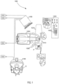
- FIG. 1 is a plan view illustration of a computer-assisted teleoperation system. Shown is a medical device, which is a Minimally Invasive Robotic Surgical (MIRS) system 1000 (also referred to herein as a minimally invasive teleoperated surgery system), used for performing a minimally invasive diagnostic or surgical procedure on a Patient P who is lying on an Operating table 1010.
- the system can have any number of components, such as a user control unit 1100 for use by a surgeon or other skilled clinician S during the procedure.
- the MIRS system 1000 can further include a manipulator unit 1200 (popularly referred to as a surgical robot), and an optional auxiliary equipment unit 1150.
- the manipulator unit 1200 can include an arm assembly 1300 and a tool assembly removably coupled to the arm assembly.
- the manipulator unit 1200 can manipulate at least one removably coupled tool assembly 1400 (also referred to herein as a "tool") through a minimally invasive incision in the body or natural orifice of the patient P while the surgeon S views the surgical site and controls movement of the tool 1400 through control unit 1100.
- tool assembly 1400 also referred to herein as a "tool”
- An image of the surgical site is obtained by an endoscope (not shown), such as a stereoscopic endoscope, which can be manipulated by the manipulator unit 1200 to orient the endoscope.
- the auxiliary equipment unit 1150 can be used to process the images of the surgical site for subsequent display to the Surgeon S through the user control unit 1100.
- the number of tools 1400 used at one time will generally depend on the diagnostic or surgical procedure and the space constraints within the operating room, among other factors. If it is necessary to change one or more of the instruments 1400 being used during a procedure, an assistant removes the instrument 1400 from the manipulator unit 1200 and replaces it with another instrument 1400 from a tray 1020 in the operating room. Although shown as being used with the instruments 1400, any of the instruments described herein can be used with the MIRS 1000.
- FIG. 2 is a perspective view of the control unit 1100.
- the user control unit 1100 includes a left eye display 1112 and a right eye display 1114 for presenting the surgeon S with a coordinated stereo view of the surgical site that enables depth perception.
- the user control unit 1100 further includes one or more input control devices 1116, which in turn cause the manipulator unit 1200 (shown in FIG. 1 ) to manipulate one or more tools.
- the input control devices 1116 provide at least the same degrees of freedom as instruments 1400 with which they are associated to provide the surgeon S with telepresence, or the perception that the input control devices 1116 are integral with (or are directly connected to) the instruments 1400. In this manner, the user control unit 1100 provides the surgeon S with a strong sense of directly controlling the instruments 1400.
- position, force, and tactile feedback sensors may be employed to transmit position, force, and tactile sensations from the instruments 1400 back to the surgeon's hands through the input control devices 1116.
- the user control unit 1100 is shown in FIG. 1 as being in the same room as the patient so that the surgeon S can directly monitor the procedure, be physically present if necessary, and speak to an assistant directly rather than over the telephone or other communication medium. In other embodiments however, the user control unit 1100 and the surgeon S can be in a different room, a completely different building, or other remote location from the patient allowing for remote surgical procedures.
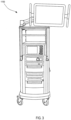
- FIG. 3 is a perspective view of the auxiliary equipment unit 1150.
- the auxiliary equipment unit 1150 can be coupled with the endoscope (not shown) and can include one or more processors to process captured images for subsequent display, such as via the user control unit 1100, or on another suitable display located locally and/or remotely.
- the auxiliary equipment unit 1150 can process the captured images to present the surgeon S with coordinated stereo images of the surgical site via the left eye display 1112 and the right eye display 1114.
- Such coordination can include alignment between the opposing images and can include adjusting the stereo working distance of the stereoscopic endoscope.
- image processing can include the use of previously determined camera calibration parameters to compensate for imaging errors of the image capture device, such as optical aberrations.
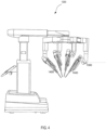
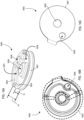
- FIG. 4 shows a front perspective view of the manipulator unit 1200.
- the manipulator unit 1200 includes the components (e.g., arms, linkages, motors, sensors, and the like) to provide for the manipulation of the instruments 1400 and an imaging device (not shown), such as a stereoscopic endoscope, used for the capture of images of the site of the procedure.
- the instruments 1400 and the imaging device can be manipulated by teleoperated mechanisms having a number of joints.
- the instruments 1400 and the imaging device are positioned and manipulated through incisions or natural orifices in the patient P in a manner such that a kinematic remote center of motion is maintained at the incision or orifice. In this manner, the incision size can be minimized.
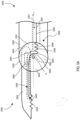
- FIGS. 5A-5C are diagrammatic illustrations of various portions of an instrument 2400, according to an embodiment.
- the instrument 2400 or any of the components therein are optionally parts of a surgical system that performs minimally invasive surgical procedures and which can include a manipulator unit, a series of kinematic linkages, a series of cannulas, or the like.
- the instrument 2400 (and any of the instruments described herein) can be used in any suitable surgical system, such as the MIRS system 1000 shown and described above.
- the instrument 2400 includes a link 2452, a transfer member 2450, a tool member 2462, and a non-drive wire 2560.
- the link 2452, the transfer member 2450, and the tool member 2462 together define a guide path 2456 through the instrument for the non-drive wire 2560.
- the instrument 2400 is intended to illustrate by way of example various aspects and features described herein. As such, it is understood that other components, parts, and connections (not shown) can be included in instrument 2400 and form portions of a wrist assembly or other articulable assembly.
- the transfer member 2450 can be configured, for example, as one or more portions of components of an articulable portion of the instrument, rather than as a primary component or link member as is illustrated in the schematic example of instrument 2400.
- FIGS. 5A-5C as well as FIGS.
- the transfer member 2450 is configured to include appropriate components and portions of components that can cooperate to transfer effectively and flexibly the non-drive wire 2560 through an articulable portion of the instrument as described in greater detail below.
- the non-drive wire 2560 has a proximal end portion 2561, a distal end portion 2562, and a central portion 2564 disposed there between.
- the proximal end portion 2561 is coupled to an energy source (not shown)
- the distal end portion 2562 is coupled to the tool member 2462
- the central portion 2564 extends from the proximal end portion 2561 to the distal end portion 2562.
- the non-drive wire 2560 can be coupled to any suitable energy source (not shown) of a surgical system, such as the MIRS system 1000 shown and described above.
- non-drive wire 2560 acts as a powered conductor to convey electrical energy and optionally data communications from the surgical system to an end effector coupled to the transfer member 2450 to perform clinical functions, such as desiccation, hemostasis, cutting, dissection, fulguration, incisions, tissue destruction, cauterizing, vessel sealing, and imaging.
- the instrument 2400 is configured for controlled movement in response to movements by one or more drive members (not shown) controlled by the surgical system, such as tension members, cables, pulley, guide members and the like.
- the link 2452 has a distal end portion 2454, and a proximal end portion (not shown) that is coupled to a manipulator unit (not shown), such as manipulator unit 1200 shown in FIG. 4 .
- the distal end portion 2454 of the link 2452 is articulably coupled to the transfer member 2450, such as rotatably coupled via one or more connectors.
- the distal end portion 2454 can be connected to the transfer member 2450 via one or more rotatable joints, pins, hinges, discs, universal joints, as well as via flexible connectors such as multi-segmented serpentine links, flexible hinges including living hinges and polymeric connections, and the like.
- the link 2452 can include a link member, such as a metal fastener, connector, clevis, or other member, which can be fixedly attached to shaft (not shown) or other member coupled, for example, to the manipulator unit.
- the transfer member 2450 includes a proximal end 2451, a distal end 2455, and a central portion 2453 located between the proximal and distal ends.
- the proximal end 2451 of the transfer member is coupled to the distal end 2454 of the link 2452 as described above.
- the distal end 2455 of the transfer member 2450 is coupled to a proximal portion 2467 of the tool member 2462 via a connector 2680.
- the tool member 2462 is articulably coupled to the transfer member 2450.
- the transfer member 2450 can include a wide variety of components including connector components that can provide for various types of articulation movements between portions of the transfer member and/or portions of other members, such as between the distal end 2454 of the link 2452 and/or the proximal end portion 2467 of the tool member 2462.
- the connector components can further include, for example, one or more rotatable joints, pins, hinges, discs, universal joints, multi-segmented serpentine links, and flexible hinges including living hinges and polymeric connections, and the like.
- the transfer member 2450 can further include guide path components, such as guide path surfaces, fixed or rotatable guides for the one or more tension members (not shown) including pulleys and guide slots.
- the transfer member 2450 can define one or more guide paths including portions of the non-drive wire guide path 2456, one or more guide surfaces for the non-drive wire and/or tension members, and one or more guide pathways or channels for other movable components.
- the transfer member 2450 can also define or include other components and features as appropriate for supporting, articulating, moving, routing connections to, controlling, and/or communicating with the tool member 2462 for the tool member to perform its intended functions.
- the transfer member 2450 defines other features or includes additional components as appropriate for transferring effectively and flexibly the non-drive wire 2560 through the transfer member 2450 to the tool member 2462.
- the instrument 2400 is configured such that the tool member 2462 can be controlled to articulate through at least two motions with respect to the link 2452 via the transfer member 2450.
- the proximal end 2451 of the transfer member 2450 is rotatably coupled to the distal end 2454 of the link 2452 to form a wrist joint that can rotate the tool member 2462 from a first orientation shown in FIG. 5A to a second orientation shown in FIG. 5B about an axis of rotation, A 1 .
- the centerline CL 1 of the link 2452, and the centerline CL 2 of the transfer member 2450 are collinear.
- the centerline CL 1 of the link 2452 forms an angle ⁇ with the centerline CL 2 of the transfer member 2450.
- the transfer member 2450 rotates with the tool member 2462, but rotates relative to the link 2452, when moving from the first orientation shown in FIG. 5A to the second orientation shown in FIG. 5B .
- the transfer member 2450 can be rotated relative to the link 2452, for example, by movement of a tension member (not shown) coupled to the transfer member 2450.
- the tension member can be any tension member shown and described herein, such as the tension member 3420 described below.
- the transfer member 2450 can receive a force applied by the moving tension member and move the tool member 2462 in response to the force.
- the slotted connector 2680 of the transfer member 2450 is coupled to a slot of the tool member 2462 such that the tool member 2462 can translate relative to the transfer member 2450, but also rotates along with the transfer member 2450 about axis A 1 .
- the slotted connector 2680 can be any suitable connector to translatably couple the tool member 2462 to the transfer member 2450 and form a sliding tool member joint. As shown in FIGS. 5A and 5C , the tool member 2462 is configured to translate distally and proximally in a direction toward and away from the transfer member 2450.
- the transfer member 2450 can include any suitable connector to movably couple the tool member 2462 to the transfer member 2450.
- the tool member 2462 includes a proximal portion 2467 and an opposite distal contact portion 2463. As described above along with the transfer member 2450, the proximal portion 2467 is movably coupled to the transfer member to articulate proximally and distally with respect to the transfer member.
- the contact portion 2463 is configured to contact, and optionally to engage, a target tissue (not shown). As described further below, the contact portion 2463 is electrically connected to an end of the non-drive wire 2560.
- the tool member 2462 can optionally include an electrically conductive engagement surface 2464 that is electrically connected to the contact portion 2463 and is configured to engage the target tissue, such as to cut, clamp, press against, or otherwise engage the target tissue in addition to making contact with the target tissue.
- the tool member 2462 can include a scalpel or other cutting device having an electrically conductive engagement surface 2464, such as a cutting edge 2464, wherein distal and proximal movements of the tool member 2462 can occur as part of cutting operations that engage the target tissue.
- a guide path 2456 for the non-drive wire 2560 is defined at least by the link 2452, the transfer member 2450, and the tool member 2462.
- a proximal end portion 2457 of the guide path 2456 provides a path for the non-drive wire 2560 as it extends from its connection to the energy source (not shown) through the link 2452.
- link 2452 defines at least a portion of the proximal end portion 2457 of the guide path.
- a central portion 2459 of the guide path extends distally from the proximal end portion 2457 of the guide path 2456, through an articulation portion of the instrument 2400, to a distal end portion 2458 of the guide path located proximate the contact portion 2463 of the tool member 2462.
- the transfer member 2450 defines a portion of the central portion 2459 of the guide path 2456.
- the distal end portion 2458 of the guide path 2456 extends to the contact portion 2463 of the tool member 2462.
- the tool member defines a portion of the distal end portion 2458 of the guide path 2456.
- the transfer member 2450 further defines a cavity 2601 within the central portion 2459 of the guide path 2456, which can be formed as an enlarged portion of the guide path 2456 that is located within the transfer member 2450.
- the cavity 2601 can be configured to retain a transition portion 2567 of the non-drive wire 2560.
- the cavity 2601 is located proximate the rotatable joint formed along the axis of rotation A 1 without including the joint, but in other embodiments the cavity can also include the joint and a corresponding axis (see e.g., FIGS. 14-16C , 17-19B and 23-25 ). As shown in FIGS.
- the cavity can extend distally inward from the proximal end 2451 of the transfer member to the central portion 2453 of the transfer member.
- the cavity can be configured, located and shaped in various arrangements as appropriate for the instrument, for the routing of the non-drive wire 2560 therein, for the amount, type and location of articulable movements, and based on other factors, such as are discussed herein.
- the cavity 2601 can be defined by the tool member 2462, the link 2452, or any combination of the transfer member 2450, the tool member 2462, and the link 2452. The cavity 2601 as shown in FIGS.
- the cavity 2601 is configured to be aligned with a distal end portion of the guide path 2456 at the distal end 2454 of the link 2452 throughout the range of rotation of the transfer member 2450, including as it moves from the first orientation ( FIG. 5A ) to the second orientation ( FIG. 5B ).
- the cavity 2601 is configured to have a general arc shape corresponding with rotation of the transfer member from the first orientation to the second orientation.
- the non-drive wire 2560 includes a proximal end portion 2561, a distal end portion 2562, and a central portion 2564 located between the proximal and distal end portions.
- the non-drive wire 2560 can be configured as an insulated conductor having an insulated outer jacket (not shown) and one or more conductive wires (not shown) located within the outer jacket.
- the proximal end portion 2561 is coupled to, and is electrically connected to, an energy source (not shown) of the surgical system, such as the MIRS system 1000 shown and described above.
- the distal end portion 2562 is coupled to, and electrically connected to, the contact portion 2463 of the tool member, such that the contact portion 2463 is electrically connected to the power source (not shown) of the surgical system.
- the non-drive wire 2560 is routed through the guide path 2456, as described above.
- the central portion 2564 of the non-drive wire 2560 includes a transition portion 2567 located within the cavity 2601 within the transfer member 2450. As shown in FIG. 5A , the transition portion 2567 has a compact first configuration that is configured to store a slack portion of the non-drive wire 2560 in an expandable, compact arrangement when the transfer member 2450 and the tool member 2462 are in the first orientation.
- the transition portion 2567 includes the non-drive wire 2560 forming a convoluted path including one or more bends, loops, curves, coils, or other curvilinear shapes 2568, or serial arrangements or combinations of the same.
- the transition portion 2567 includes a bight when in the compact first configuration.
- the transition portion can be in a relaxed state when in the compact first configuration. Further, in some embodiments, the transition portion 2567 can be biased toward the compact first configuration.
- the instrument 2400 is configured to route the non-drive wire 2560 in an efficient curvilinear manner that closely follows its designated route through the instrument via the guide path 2456.
- the instrument does so without having slack portions that form bends extending outside of the transition portion 2567.
- the transition portion 2567 is located proximate an articulable connection along the instrument 2400 including at the rotatable connection between the link 2452 and the transfer member 2450, and near the translatable connector 2680 that slidably connects the transfer member to the tool member 2462. In such an arrangement, the formation of excess bends or other regions of slack material of the non-drive wire 2560 are avoided.
- non-drive wire 2560 is shown as including one transition portion 2567, in other embodiments a non-drive wire can include any suitable number of transition portions.
- articulable instrument 2400 is shown when in the non-rotated first orientation ( FIG. 5A ) and in the rotated second orientation ( FIG. 5B ), in which the transfer member 2450 rotates counterclockwise by ⁇ about axis A 1 with respect to the link 2452 (e.g., about 90 degrees).
- the transition portion 2567 is in the first compact configuration within the cavity 2601 and is located proximate to axis A 1 . Further, the transition portion 2567 includes a plurality of bends 2568 arranged in series when in the first orientation.
- the transition portion 2567 can be biased to return when there is a lack of tension in the longitudinal direction of the non-drive wire.
- Such bias toward the first compact configuration of FIG. 5A can be provided by the bends 2568 having been formed as bends that exceed the elastic limit of the conductive wire that have been induced in the non-drive wire 2560 at the transition portion, such that the conductive wire is deformed to retain the bends when in the relaxed state. It is understood that such a bias can be provided by any appropriate mechanism including by having different configurations of expandable folds or loops formed therein (see e.g., FIGS. 10 , 19A , 19B and 23-25 ), and/or via the use of a biasing mechanism (not shown).
- a biasing member can include an elastic band formed around at least part of the transition portion, a shaped elastomeric jacket formed around the non-drive wire within the transition portion, or an elastic compressive member integrated with the non-drive wire within the transition portion.
- the transition portion can further include a release portion 2565 located within the cavity 2601 that is configured to move out of the cavity when the transition portion expands from the first compact configuration.
- the transition portion 2567 expands to the second expandable configuration shown in FIG. 5B , which releases a length of the non-drive wire 2560 appropriate to avoid the non-drive wire from limiting the rotation.
- the release portion 2565 can be located within the cavity 2601 at a distal end of the transition portion 2567 proximate an exit portion of the cavity.
- the release portion 2565 can move at least partially out of the cavity 2601, such that it is located at the exit portion of the cavity and extends into the distal end portion 2458 of the guide path 2456 defined within the tool member 2462.
- the transition portion 2567 releases a length of the non-drive wire by extending to an expanded second configuration having, for example, fewer bends 2568 and/or the bends with less amplitude and frequency than in the compact first configuration. As such, a shorter length of the non-drive wire 2560 is retained by the transition portion 2567.
- the transition portion 2567 further extends to the second expanded configuration shown in FIG. 5C as the tool member 2462 articulates again to translate distally away from the transfer member 2450 along the pinned connection 2680.
- the further extension of the transition portion releases an additional length of the non-drive wire 2560 that is appropriate to avoid the non-drive wire 2560 from limiting the distal translation.
- the release portion 2565 can move, for example, out of the cavity 2601 and distally along the guide path 2456 toward the tool member 2462.
- the transition portion 2567 releases the additional length of the non-drive wire by further extending to the expanded second configuration of FIG. 5C .
- the transition portion 2567 has fewer, if any, bends 2568 in comparison with the first expanded configuration of FIG. 5B , and any remaining bends have less amplitude with reduced frequency.
- non-drive wire guide mechanisms can be provided to route the non-drive wire in an efficient curvilinear manner that closely follows its designated route through the instrument without having slack portions that can form bends.
- Such guide mechanisms can operate alone, or in combination with, the transition portions that are configured to provide flexibility for the non-drive wire when needed for articulable instrument movements.
- an articulable medical instrument can also include one or more feed mechanisms configured to assist with providing flexibility to the non-drive wire for the articulation movements of the medical instrument.
- FIGS. 6A and 6B are schematic drawings showing an example instrument 3400 having a feed mechanism that operates in combination with one or more transition portions to provide efficient routing and articulation flexibility for a non-drive wire routed there through.
- instrument 3400 or any of the components therein are optionally parts of a surgical system that performs minimally invasive surgical procedures and which can include a patient-side cart, a series of kinematic linkages, a series of cannulas, or the like.
- the instrument 3400 (and any of the instruments described herein) can be used in any suitable surgical system, such as the MIRS system 1000 shown and described above.
- instrument 3400 is shown, which is similar to instrument 2400 and generally includes the same preferences and features as described above along with instrument 2400 except as described hereafter. Accordingly, like numbers refer to like features as described above.
- instrument 3400 also includes a link 3452, a transfer member 3450, a tool member 3462, and a non-drive wire 3560, in which the non-drive wire 3560 is coupled to an energy source (not shown) of the surgical system, such as the MIRS system 1000 shown and described above.
- instrument 3400 includes at least one tension member 3420.
- the instrument 3400 is configured for controlled movement in response to movements by one or more tension members including the tension member 3420, and/or by one or more additional drive members (not shown) that are controlled by the surgical system, such as additional tension members, cables, pulleys, guide members and the like.
- Instrument 3400 also differs from instrument 2400 in that the link 3452 and the tool member 3462 together define a guide path 3456 through the instrument for the non-drive wire 3560, and the transfer member 3450 can be configured, for example, as one or more portions thereof.
- the transfer member 3450 can include articulable portions of the link 3452 and the tool member 3462 as appropriate to flexibly and efficiently transfer the non-drive wire 3560 through an articulable portion of the instrument as described in greater detail below.
- the link 3452 defines therein a proximal end portion 3457 of the guide path 3456 for the non-drive wire 3560.
- a distal portion of the guide path 3456 can be defined through the tool member 3462.
- the tool member 3462 includes a distal contact portion 3463, which is electrically conductive and is configured to contact a target tissue (not shown).
- the tool member 3462 also includes a pulley portion 3467 at its proximal end portion.
- the pulley portion 3467 is rotatably coupled to the link 3452 in a similar manner as the rotatable connection along axis A 1 between the transfer member 2450 and the link 2452 of instrument 2400.
- the pulley portion 3467 can be rotatably coupled to the link, such as via a pinned connection, a joint, a flexible connector, a rotatable assembly or other device or combination of devices.
- the tool member 3462 can define therein a distal end portion 3458 of the guide path 3456 for the non-drive wire 3560, which can couple with the central portion 3459 defined in the link 3452.
- a cavity 3601 is also defined within the pulley portion 3467 along a portion of the central portion 3459 of the guide path 3456.
- the instrument 3400 is described as including both a transfer member 3450 and a tool member 3462 having a pulley portion 3467, in some embodiments, the instrument 3400 can include only a pulley portion to accomplish the actuation of the tool member 3462 when the tension member 3420 is moved.
- the pulley portion 3467 is described as being separate from the transfer member, in some embodiments, the pulley portion 3467 can monolithically constructed as a part of the tool member, and can function as the transfer member.
- the non-drive wire 3560 has a proximal end portion 3561, a distal end portion 3562, and a central portion 3564 disposed therebetween.
- the proximal end portion 3561 is coupled to an energy source (not shown)
- the distal end portion 3562 is coupled to the tool member 3462
- the central portion 3564 extends from the proximal end portion 3561 to the distal end portion 3562.
- the non-drive wire 3560 can be coupled to any suitable energy source (not shown) of a surgical system, such as the MIRS system 1000 shown and described above.
- the central portion 3564 of the non-drive wire 3560 includes a transition portion 3567, which is disposed within the cavity 3601 within the pulley portion 3467 of the tool member 3462.
- the central portion 3564 of the non-drive wire 3560 also includes a feed portion 3566 that is located outside of the cavity 3601 when the instrument 3400 is in the first orientation shown in FIG. 6A .
- the instrument 3400 is configured such that the tool member 3462 can be controlled to articulate through at least one motion with respect to the link 3452 via the transfer member 3450.
- the pulley portion 3467 of the tool member 3462 is rotatably coupled to the distal end 3454 of the link 3452 to form a wrist joint that can rotate the tool member 3462 with respect to the link about axis A 1 .
- the tool member 3462 can be rotated from a first orientation shown in FIG. 6A to a second orientation shown in FIG. 6B about the axis of rotation, A 1 .
- the tool member 3462 can be rotated relative to the link 3452 when tension member 3420 is moved, which in the embodiment shown is coupled to the tool member 3462.
- the tension member 3420 can optionally be coupled to a second tool member (not shown) in an alternative arrangement, and can also be coupled to the tool member 3462 and the second tool member.
- the tension member 3420 can be coupled to a separate transfer member 3450 that transfers the force from the tension member to the tool member 3462.
- the tension member 3420 (and any of the tension members described herein) can be formed as a cable made of Tungsten or stainless steel to provide sufficient strength, bendability, and durability.
- cables can be constructed from multiple braids of fine wire, to provide strength and resiliency.
- cables can be made from 150 to 350 braids of 0.0007-inch to 0.001-inch (0.01778 mm to 0.0254 mm) diameter tungsten wire providing cables with outer diameters of 0.014 inches to 0.018 inches (0.3556 mm to 0.4572 mm).
- the instrument 3400 (and any of the instruments described herein) can include a tension band, of the types shown and described in U.S. Patent Application No.
- such bands can have a trapezoidal shape.
- such bands can include slightly curved surfaces.
- such bands can be constructed from any suitable materials.
- such bands can be constructed from a series of laminates that are bonded together (e.g., via an adhesive). The laminates can be constructed from any suitable material, including tungsten, steel, or any suitable polymer.
- the tension member 3420 has a proximal end portion 3421, a distal end portion 3422 coupled to the tool member 3462, and a central portion 3423 between the proximal and distal end portions.
- the proximal end portion 3421 can be coupled to the surgical system at a first end thereof (not shown), such as the MIRS system 1000 shown and described above.
- the tension member 3420 is coupled to the tool member 3462 to rotate the tool member 3462 when the tension member moves.
- the instrument 3400 can be configured, for example, such that when the tension member 3420 moves in the distal direction indicated by the arrows in FIGS. 6A and 6B , the tool member 3462 rotates from the first orientation shown in FIG. 6A to the second orientation shown in FIG. 6B .
- the tension member 3420 and the tool member 3462 are coupled to each other so that when the tension member moves in the distal direction of the instrument 3400, the tool member 3462 rotates from the first orientation to the second orientation.
- the articulable instrument 3400 is shown in FIG. 6A when in the non-rotated first orientation, and in FIG. 6B when in the rotated second orientation after the tool member 3462 has rotated counterclockwise by ⁇ about axis A 1 with respect to the link 3452.
- the transition portion 3567 of the non-drive wire 3560 is in a relaxed state and the feed portion 3566 is located outside of the cavity 3601.
- the transition portion 3567 expands to the second expandable configuration shown in FIG. 6B , which releases a length of the non-drive wire 3560 appropriate to avoid the non-drive wire from limiting the rotation.
- the transition portion 3567 releases a length of the non-drive wire by extending to an extended second state having, for example, fewer bends 3568 and/or the bends with less amplitude and frequency than in the compact first configuration. As such, a shorter length of the non-drive wire 3560 is retained by the transition portion 3567.
- movement of the tension member 3420 as shown in FIGS. 6A and 6B also causes the feed portion 3566 of the non-drive wire 3560 to move from a first position outside of the cavity 3601 as shown in FIG. 6A , to a second position inside of the cavity when the tension member 3420 moves to rotate the tool member 3462.
- the tension member 3420 is coupled to the non-drive wire 3560 such that movement of the tension member 3420 causes the feed portion 3566 to move from its first position to its second position when the tension member 3420 moves.
- the tension member 3420 can assist in moving the non-drive wire to avoid the non-drive wire from limiting the rotation or otherwise producing excess lengths that can become pinched.
- the tension member 3420 can be coupled to the non-drive wire 3560 in any suitable manner and at any suitable location.
- a proximal end 3421 of the tension member can be coupled to the proximal end portion 3561 or the central portion 3564 of the non-drive wire 3560.
- the tension member 3420 can be coupled to the non-drive wire via a connector 3570 that connects the tension member to the non-drive wire along a length of each.
- the connector 3570 can be any appropriate connector for sufficiently coupling the non-drive wire 3560 to the tension member 3420.
- Such a connector can be configured so that when the tension member moves to rotate the tool member 3462, the tension member additional moves (i.e., pulls) the non-drive wire via the connector 3570 to move the feed portion 3566 distally toward the cavity 3601.
- the connector 3570 can include an elastomeric connector that can surround both the tension member and the non-drive wire, such as a shrink wrap type connector. As such, the movement of the tension member 3420 can push the non-drive wire 3560 to move the feed portion 3566 into the cavity 3601 when the tool member 3462 rotates from the first orientation to the second orientation.
- the instrument 3400 can operate in a push-pull manner to provide flexibility for portions of the non-drive wire 3560 that are routed through articulable portion of the instrument 3400 during movements of the instrument.
- the instrument 3400 can be configured to route the non-drive wire 3560 in an improved, curvilinear manner that can more closely follow its designated route through the instrument via the guide path 3456 compared with configurations providing only push or pull functionality to help improve the flexibility of the non-drive wire routed therethrough with respect to articulation movements of the instrument.
- beneficial arrangements of a transfer member that effectively and flexibly routes a non-drive wire through an articulable portion of an instrument can be provided for more complex instruments and drive arrangements.
- beneficial aspects and features pertaining to a transfer member described above can be used for routing a non-drive wire through a complex, amplified force drive arrangement for an instrument 4400 having a relatively complex amplified force driving arrangement for a pair of tool members to which a corresponding pair of non-drive wires are attached.
- the instrument 4400 includes a transfer member that effectively routes the non-drive wires through the articulation portions of the amplified force drive mechanism along with providing appropriate flexibility for the non-drive wires during articulation movements of drive mechanism.
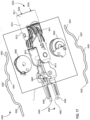
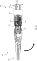
- FIGS. 7-13 show various views of an instrument 4400, according to an embodiment, which generally includes the same preferences and features as described above along with instruments 2400 and 3400 except as described hereafter. Accordingly, like numbers refer to like features as described above.
- the instrument 4400 or any of the components therein are optionally parts of a surgical assembly that performs minimally invasive surgical procedures, and which can include a manipulator unit, a series of kinematic linkages, a series of cannulas, or the like.
- the instrument 4400 (and any of the instruments described herein) can be used in any suitable surgical system, such as the MIRS system 1000 shown and described above.
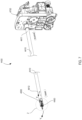
- the instrument 4400 includes a transmission assembly 4700 (that can function as an actuator mechanism), an instrument shaft 4410, a wrist assembly 4500, and an end effector 4460.
- instrument 4400 also includes a link configured as a proximal first link 4510, a pulley 4660 (that functions as a transfer member), a tool member 4462 formed as part of an end effector 4460, and a non-drive wire 4560 that is coupled to an energy source (not shown) of the surgical system, such as the MIRS system 1000 shown and described above.
- instrument 4400 further includes a second tool member 4482 that is also part of the end effector 4460.
- Each of the pair of tool members are coupled to the second link 4610 in an opposing relationship with each other, so that the pair of tool members can cooperate with each other to clamp, grasp, or otherwise interface with a target tissue (not shown).
- the instrument 4400 also includes a second non-drive wire 4580 that corresponds with the second tool member 4482, which is similarly coupled to the second tool member 4482 at one end portion and to an energy source (not shown) at another end portion.
- the pair of tool members 4462, 4482 can each make contact with the target tissue (not shown), and become energized while each are in contact with the target tissue such that an electrical current can flow through the tissue to cauterize or otherwise affect the tissue.
- the instrument 4400 further includes one or more tension members (not shown), which have been omitted in FIGS. 7-13 to more clearly show features pertaining to the non-drive wires 4560 and 4580 and routing of the same via the pulley 4660.
- the instrument 4400 generally includes multiple tension members (not shown) that couple the transmission mechanism 4700 to the wrist assembly 4500.
- the instrument 4400 is configured such that movement of the tension members can produce rotation of the wrist assembly 4500 (i.e., pitch rotation) about a first axis of rotation, A 1 , yaw rotation of the end effector 4460 about a second axis of rotation, grip rotation of the tool members of the end effector 4460 about the yaw axis A 2 , or any combination of these movements.
- the instrument 4400 is configured to perform a variety of articulation movements along portions of the wrist assembly 4500 and the end effector 4460. As such, it can be challenging to route the one or more non-drive wires 4560, 4580 through the articulable portions of the wrist assembly 4500 to the tool members 4462, 4482 located at the distal end of the instrument. Moreover, it can be even more difficult to route the non-drive wires in a manner that avoids adversely affecting the articulation movements of the instrument 4400, and that avoids excess slack portions of the non-drive wire gathering within the instrument 4400.
- the instrument 4400 also includes a force-amplification arrangement within the wrist assembly 4500 that employs mechanical advantage principles to amplify the forces applied to the end effector 4460.
- a force-amplification arrangement within the wrist assembly 4500 that employs mechanical advantage principles to amplify the forces applied to the end effector 4460.
- such an arrangement can add complexity to the drive and the linkage components located within the wrist assembly 4500 and the end effector 4460.
- the use of more complex articulation components can reduce available space within the instrument 4400 that could be used for routing the non-drive wires and other components, and can also increase the likelihood of interference between internal components and the non-drive wires during articulation movements involving additional components moving in a tighter space.
- the pulley 4660 and the pulley 4665 can be highly beneficial for desired operation and movements of the instrument 4400.
- the pulleys 4660, 4665 are configured to efficiently route the non-drive wires 4560, 4580 through the articulation portions of the instrument 4400, as well as to maintain the non-drive wires within their guide paths during articulation movements. Doing so can avoid interfering contact between the non-drive wires and moving components, and can further provide flexibility for the non-drive wires during articulation movements such that the non-drive wires avoid limiting the ranges and types of movements that can be performed by the instrument 4400.
- These features can be particularly beneficial for articulable portions of an instrument that include complex linkages and drive members, such as force amplification features as described below along with FIG. 10 .
- the transmission mechanism 4700 produces movement of the plurality of tension members (not shown), which operate to produce the desired articulation movements (pitch, yaw, or grip) at the wrist assembly 4500.
- the transmission mechanism 4700 includes components and controls to move some of the tension members in a proximal direction (i.e., to pull in certain tension members) while simultaneously allowing the distal movement (i.e., releasing or "paying out") of other of the tension members in equal lengths. In this manner, the transmission mechanism 4700 can maintain the desired tension within the tension members, and can ensure that the lengths of the tension members are conserved (i.e., moved in equal amounts) during the entire range of motion of the wrist assembly 4500.
- the transmission assembly 4700 can be any of the transmission assemblies shown and described in International Patent Application No. PCT/US2017/062258, (filed Nov. 14, 2017 ), entitled “Cable Length Conserving Medical Instrument.” In other embodiments however, conservation of the lengths of the tension members is not required.
- the articulable wrist mechanism 4500 of the instrument 4400 is coupled to the shaft 4410, which can be any suitable elongated shaft that couples the wrist assembly 4500 to the transmission mechanism 4700.
- the instrument shaft 4410 includes a proximal end portion 4411 that is coupled to a housing of the transmission mechanism 4700, and a distal end portion 4412 that is coupled to the wrist assembly 4500.
- the instrument shaft 4410 defines a passageway or series of passageways through which the tension members, the non-drive wires 4560, 4580 and other components (e.g., electrical wires, ground wires, or the like) can be routed from the transmission mechanism 4700 to the wrist assembly 4500.
- These passageways or series of passageways include portions of the guide paths for routing the non-drive wires 4560 and 4580 as discussed in more detail below.
- the instrument shaft 4410 can have any suitable shape.
- the wrist assembly 4500 includes a proximal first link 4510 and a distal second link 4610, which is articulably coupled to an end effector 4460.
- the first link 4510 has a proximal end portion 4511 and a distal end portion 4512.
- the proximal end portion 4511 is coupled to the distal end portion 4412 of the instrument shaft 4410.
- the distal end portion 4512 includes a joint portion 4540 that is rotatably coupled to a mating joint portion 4640 of the second link 4610.
- first link 4510 and the second link 4610 form the wrist assembly 4500 having a first axis of rotation A 1 (also referred to as the pitch axis) about which the second link 4610 can rotate relative to the first link 4510.
- a pin 4543 extends through the distal end joint portion and the second link joint portion to rotatably couple the second link 4610 to the first link 4510.
- the first link 4510 and the second link 4610 define a longitudinal centerline CL that intersects the pitch axis A 1 when the instrument is in an initial (or "straight" configuration).
- the first link 4510 defines various bores and/or guide paths that can contain (or allow passage of) various components of the wrist assembly including the non-drive wires as discussed below, as well as, for example, bores and guide paths for the tension members (not shown) and various electrical components and connections.
- the distal second link 4610 has a proximal end portion 4611 and a distal end portion 4612.
- the proximal end portion 4611 includes a joint portion 4640 that is rotatably coupled to the joint portion 4540 of the first link 4510.
- the distal end portion 4612 of the second link 4610 includes a connector 4680 that is coupled to the end effector 4460. In this manner, the first tool member 4462 and the second tool member 4482 of the end effector 4460 can rotate relative to the second link 4610 about a second axis of rotation (also referred to as the yaw axis).
- the connector 4680 is a pin-type connector and includes the pin 4683 which is supported by (and placed within) the pin openings.
- the connector 4680 can include any of the structure and features of the pinned joints shown and described in U.S. Patent No. 9,204,923 B2 (filed Jul. 16, 2008 ), entitled “Medical Instrument Electronically Energized Using Drive Cables.”
- the second axis of rotation also referred to as the yaw axis
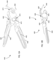
- the instrument 4400 provides for up to three degrees of freedom (i.e., a pitch motion about the first axis of rotation A 1 , a yaw rotation about a second axis of rotation, and a grip motion about the second axis of rotation).
- the first and second tool members 4462 and 4482 of the end effector 4460 each include a contact portion 4463, 4483 and a proximal portion 4467, 4487 coupled to a respective pulley 4660, 4665.
- the contact portions 4463, 4483 are each configured to engage or manipulate a target tissue (not shown) during a surgical procedure. Although shown as being a gripping surface, in other embodiments, the contact portions 4463, 4483 can be any suitable surface of the types shown and described herein (e.g., a cutter, a tissue manipulator, a cauterizing surface, or the like).
- the pulleys 4660, 4665 are each rotatably coupled to the second link 4610 via the pin 4683. As described along with FIG.
- each pulley 4660, 4665 functions as a transfer member to drive movement of a corresponding one of the tool members 4462, 4482 when rotated, such as when a tension member (not shown) applies a tensile force along a perimeter portion of a pulley.
- the first and second tool members 4462, 4482 can each rotate about the pin 4683 and relative to the second link 4610 via a second axis of rotation as described in further detail below along with FIG. 10 .
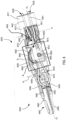
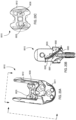
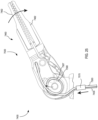
- each of the non-drive wires 4560, 4580 are highlighted in FIG. 8 to show the route of each of the non-drive wires within the instrument 4400.
- the non-drive wires are shown as overlays on the wrist mechanism 4500 and the end effector 4460 for clarity purposes. However, it is understood that each of the non-drive wires 4560, 4580 are routed within the guide paths defined therein as discussed in below.
- each of the non-drive wires 4560, 4580 includes a corresponding proximal end portion 4561, 4581 at one end that is coupled to an energy source (not shown), and which extends through one or more guide pathways (not shown) defined within the shaft 4410 to the articulable wrist mechanism 4500.
- each of the non-drive wires 4560, 4580 are coupled at an opposite distal end portion 4562, 4582 to the contact portion 4463, 4483 of the engagement surface 4484 of a corresponding one of the tool members 4462, 4482.
- Each of the non-drive wires 4560, 4580 further includes a central portion 4564, 4584 that is located between the corresponding distal end portion and the proximal end portion for the particular non-drive wire as it extends through the instrument 4400.
- a guide path 4456, 4496 is defined through the instrument 4400 for each of the non-drive wires 4560, 4580 to guide the wires along a desired route through within the instrument.
- Each wire extends distally along the corresponding guide path from its proximal end portion 4561, 4581 coupled to the energy source (not shown) to the distal end portion 4562, 4582 coupled to a corresponding contact portion 4463, 4483.
- a first guide path 4456 for the first non-drive wire 4560 and a second guide path 4496 for the second non-drive wire 4580 are each defined in the instrument 4400 including within the wrist mechanism 4500 and the end effector 4460.
- Each of the guide paths 4456, 4496 guide the corresponding non-drive wire 4560, 4580 to extend through the instrument 4400 along the designated route, which helps avoid interfering contact between the non-drive wires 4560, 4560 and components of the instrument 4400 during articulation movements of the instrument.
- Each of the guide paths 4456, 4496 includes smaller guide pathways that together form the route provided by the guide paths 4456, 4496.
- a first and second guide pathway 4535, 4536 are defined through the first link 4510 of the wrist mechanism 4500 for each of the non-drive wires 4560, 4580.
- the proximal end portions 4561, 4581 of the non-drive wires extend distally along a corresponding one of the guide paths 4456, 4496 from being coupled to an energy source (not shown) at their proximal end, along one or more pathways defined in the shaft 4410, to the pathways 4535, 4536 defined through the first link 4510 of the wrist mechanism 4500.
- the guide paths 4456, 4496 continue to guide the non-drive wires from within the first link into through similar corresponding pathways 4635, 4636 defined in the second link 4610 that guide each of the non-drive wires 4560, 4580 to the corresponding one of the pulleys 4660, 4665 that function as transfer members.
- the guide paths 4456, 4496 further include guide pathways 4470, 4490 defined within the tool members 4462, 4482, which guide the non-drive wires 4560, 4580 along the guide paths 4456, 4496 from each of the corresponding pulleys 4660, 4665, through the openings 4473, 4493, and into the corresponding guide pathway 4470, 4490 defined within the tool members 4462, 4482.
- the tool member guide pathways guide the non-drive wires 4560, 4580 within the corresponding tool member to the contact portion 4463, 4483 located a distal end portion of each tool member.
- Each of the non-drive wires are coupled to a corresponding one of the contact portions at their distal end portions, which completes their route within and through the instrument along the guide paths 4456, 4496.
- the central portions 4564, 4584 of each of the non-drive wires 4560, 4580 are routed through the first and second pulleys 4660, 4665 according to the transfer member functionality provided by the pulleys, such that the non-drive wires 4560, 4580 avoid making interfering contact with any of the components during articulation movements.
- the transfer member functions provided by the first and second pulleys 4660, 4665 provide flexibility during articulation movements to the non-drive wires 4560, 4580, so that the non-drive wires do not limit the range of articulation movements that the instrument 4400 can perform.
- each of the pulleys 4660, 4665 are configured to effectively guide the central portions of the non-drive wires through the force transmission linkages discussed below along with FIG. 10 with respect to force amplification mechanisms of the instrument, which can provide clamping forces or other applied forces to the tool members 4462, 4482 while also performing transfer member functions for the non-drive wires.
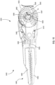
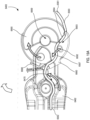
- an example force amplification arrangement is shown for the instrument 4400, which can be used with other articulable instruments along with providing similar transfer member functions.
- the force amplification arrangement between the components shown in FIG. 10 operate to provide high forces at the contact portions 4463, 4483 of the tool members without increasing the driving force transmitted to the instrument 4400 and without increasing the size or envelope (e.g., the overall diameter) of the instrument wrist assembly 4500.
- the example force amplification mechanisms described herein along with FIG. 10 are provided for illustration purposes along with describing advantageous aspects and features pertaining to the transfer member functions of the pulleys 4660, 4665 and the non-drive wires 4560, 4580 routed therein. As such, it is understood that many different drive mechanisms and other force transmission options can be used with the instrument 4400.
- the example force amplification mechanism shown in FIG. 10 includes multiple tension members (not shown) including at least one tension member (not shown) that is coupled at a distal end portion thereof to pulley 4660.
- the tension member coupled to the pulley 4660 can be located within an outer groove 4661 defined in a perimeter portion of the pulley 4660, which is configured to apply a tensile force to the rotatable pulley 4660 to rotate the pulley.
- the pulley 4660 can be directly connected to the corresponding articulable tool member 4462 such that the tool member rotates along with the pulley about a rotation axis 4683 of the pulley.
- the tensile force applied by the tension member (not shown) to a perimeter portion of the pulley 4660 in such a direct rotation arrangement provides a torque about the rotary axis of the pulley 4660.
- the torque applied to the pulley urges the pulley to rotate about its axis, as well as the tool member to likewise rotate about the same axis.
- the applied force transmitted to the contact portion 4463 of the tool member would be a function of the tensile force transmitted by the tension member to the pulley in accordance with a ratio of the radial distance from the rotary axis 4683 of the pulley at which the tension member transmitted the tensile force to the perimeter portion of the pulley (i.e. the moment arm of the tensile force applied to rotate the pulley) vs. the rotation distance that the contact portion 4463 extends from the same rotary axis (i.e., the moment arm of the contact portion along the tool member).
- the tensile force transmitted to the pulley by the tension member could also be increased.
- the size (radius) of the pulley could also be increased to provide a longer moment arm at the pulley and thus a larger applied drive torque at the pulley.
- the length (moment arm) of the tool member could be decreased to thereby increase the driven force provided at the contact portion of the tool member from the rotational drive torque transmitted to the pulley about its rotary axis.
- the force amplification arrangement shown in FIG. 10 can operate to transmit higher forces at the contact portion 4463 of the tool member 4462 without increasing the radius of the pulley 4660, the tensile force transmitted to the pulley by the tension member (not shown), and/or the envelope (overall diameter) of the instrument 4400. Further, such higher forces can likewise be provided by the force amplification arrangement of FIG. 10 without decreasing the overall length of the tool member that extends distally from the wrist assembly or the relative distal location of the contact portion 4463. Rather, the force amplification arrangement shown in FIG. 10 increases the force applied to the tool member 4462 by separating the pivot about which the pulley 4660 rotates from the pivot about which the tool member 4462 rotates.
- pivot openings 4469, 4489 and the pivot pin 4472 about which the tool members rotates is offset distally along the instrument 4400 from the pulley pivot.
- a force transmitting pin 4494 within the opening 4608 couples the pulley 4660 to the tool member 4462 at a position behind the pivot 4489 of the tool member and at a greater distance (i.e., moment arm) from the tool member pivot compared with the radial distance from the pulley pivot 4683.
- the moment arm for the drive torque that is applied to the tool member 4462 is greater in the force amplification arrangement shown in FIG. 10 (i.e., the drive torque is increased for the same tensile force transmitted by the tension member) than the drive torque that would be provided by the same tensile force applied to the pulley in a direct rotary force transmission mechanism. Further, the moment arm for the tool member 4462 is decreased for the force amplification arrangement shown in FIG. 10 .
- the driven force transmitted to the end of the tool member is increased based on the decreased distance from the tool member to its pivot point (i.e., the reduced moment arm for the driven/received torque at the tool member).
- such an arrangement can increase challenges for avoiding interference between components during articulation movements if the overall diameter of the instrument is not increased.
- such an arrangement increases the number of movable components within the instrument, which further reduces available space within the instrument for routing additional components, such as non-drive wires.
- the force amplification arrangement increases the complexity of articulation movements due to a reverse torque arrangement that rotates the pulley 4660 in an opposite rotation direction than the tool member when a tensile force is applied to the pulley, as well as due to additional linkage provided by coupling the pulley 4660 to the tool member 4462.
- the force amplification arrangement shown in FIG. 10 reduces available space for routing a non-drive member therein, increases the likelihood of any excess slack in the non-drive member interfering or being caught by the articulation linkages and components, and eliminates portions of space within the instrument in which slack or flexible portions of the non-drive wire could be located to avoid limiting articulation movements. Further, the additional linkages in the force amplification arrangement shown in FIG. 10 can increase the amount of flexibility needed for routing a non-drive wire through the instrument.
- the first and second pulleys 4660, 4665 are shown that function as transfer members that provide efficient, tightly controlled routing of the non-drive wires 4560, 4580 within the instrument 4400 and through the force amplification mechanism such that the non-drive wires avoid contact with the movable linkages and components during articulation movements, while also providing appropriate flexibility for the non-drive wires 4560, 4580 to avoid limiting the articulation movements.
- the cavity 4601 is defined within an outer portion of each of the tensile force drive pulleys 4660, 4665, which closely guides the route of the non-drive wires 4560, 4580 proximate the force amplification linkages for the tool members 4462, 4482.
- an outer side of the pulleys 4660 defines a cavity 4601 therein.
- the cavity can extend around the pivot 4669 about which the pulley 4660 rotates without encompassing or including the pivot 4669, which is shown in FIGS. 11A and 11B as an opening for a pivot pin.
- the cavity 4601 can be defined as a cavity within the pulley that extends around a portion of a perimeter region of the pulley without fully extending around the pivot 4669.
- the cavity 4601 is defined within the pulley 4660 about the pivot 4669 extending less than 360 degrees around the pivot 4669.
- the cavity includes a deep guide portion 4606 and a shallow wire entry sector 4605, which can partially overlap as shown in FIGS. 11A and 11B .
- the deep guide portion 4606 is defined between a pair of high walls 4602, which can extend the full thickness of the pulley 4660.
- the pair of high walls can be described as being high and the corresponding guide portion 4606 can be described as being deep, it is understood that the pulley 4660 can be oriented in a lateral position such that the cavity 4601 and deep guide portion 4606 can be defined within lateral portions of the pulley as arranged within the instrument 4400.
- the deep guide portion 4606 of the pulley 4660 extends around a portion of the pulley along which a proximal end of the guide path 4470 that is defined within the tool member 4462 moves with respect to the pulley 4660 for the range of articulation movements between the pulley 4660 and the tool member 4462.
- the deep guide portion 4606 outlines a range of positions for the entrance portion of the tool member guide path 4470 that receives the non-drive wire 4560 as it exits the cavity 4601 of the pulley 4660 along its distal route extending from the pulley 4660 to the contact portion 4463 of the tool member 4462.
- a pair of walls having a height H 2 as shown in FIGS. 11A and 11B extend around the deep guide portion 4606 including a tall outer perimeter wall 4602 that forms a boundary along with the inner wall for the non-drive wire 4560, which maintains the non-drive wire 4560 within the deep guide portion 4606 except for guiding the non-drive wire to continue along its route within the guide path 4456.
- the deep guide portion 4606 guides the non-drive wire 4560 to stay within the portion of the cavity within the deep guide portion other than to follow the route of its guide path and extend into the guide path 4470 defined within the tool member.
- the remainder of the cavity 4601 is outlined along the outer perimeter portion of the pulley 4660 by a comparatively short outer wall 4604 having a shorter height, H 1 , which forms a low, outer perimeter boundary along a portion of the cavity 4601.
- the short outer wall 4604 has a height, H 1 , that is less than the thickness of the pulley 4660.
- the short outer wall 4604 outlines a wire entry sector 4605 of the pulley, which operates to provide additional flexibility for the non-drive wires as needed during articulation movements.
- FIG. 10 an enlarged view of the region "K" indicated in FIG. 8 is shown for the instrument 4400 in a first orientation, in which the end effector 4462 is a non-rotated orientation and the tool members 4462 and 4482 are in a closed position.
- the highlighted non-drive wires 4560 and 4580 shown in FIG. 8 for discussion purposes are not reproduced in the enlarged view of region K shown in FIG. 10 .
- the second link 4610 has been removed to expose the pulley 4660 and the path of the central portion 4564 of the non-drive wire 4560 extending through guide path portions of the pulley 4660 as part of the transfer member functionality provided by the pulley.
- the cavity 4601 formed within the pulley is shown, as well as a transition portion 4567 of the non-drive wire 4560 that is located within the cavity 4601.
- the transition portion 4567 When in the non-rotated first orientation of FIGS. 8 and 10 , in which the end effector 4460 is oriented in a straight orientation in alignment with the second link 4610, and further when the tool members 4462 and 4482 are in a closed position, the transition portion 4567 is in a first compact configuration within the cavity 4601. Further, the transition portion 4567 includes at least one bend 4568 while in the first compact configuration and includes a feed portion 4566 of the non-drive wire that is located outside of the cavity 4601. Similar in many respect to the instrument 3400 described above, the pulley 4660 is rotatble relative to the first and second link members 4510 and 4610 between a first orientation shown in FIGS.
- the pulley is configured to be coupled to at least one tension member (not shown) that can be located within an outer groove of the pulley and coupled to the pulley such that, when the tension member (not shown) is moved, the first tool member 4462 is rotated with respect to the first link member 4510 and/or the second link member 4610.
- the tension member (not shown) can be coupled to the pulley 4660 in a force amplification arrangement in which the tension member is located within an outer groove of the pulley and connected to a perimeter portion of the pulley to apply a tensile force to the perimeter portion of the pulley.
- a force amplification arrangement in which the tension member is located within an outer groove of the pulley and connected to a perimeter portion of the pulley to apply a tensile force to the perimeter portion of the pulley.
- the tension member when the tension member (not shown) is moved away from the pulley, it applies a tensile force to the pulley 4660 at its perimeter portion that imparts a torque to the pulley that rotates the pulley in the clockwise direction shown in FIG. 10 .
- rotation of the pulley 4660 in the clockwise direction due to movement of the tension member causes the first tool member 4462 to rotate in a counterclockwise direction about the distally offset pivot 4489 of the end effector 4460.
- the first tool member 4462 rotates from the non-rotated, closed end effector, first orientation of FIG. 8 to an open end effector orientation in which the tool member 4462 is rotated with respect to the first link 4510 and the second link 4610.
- the pulley rotates clockwise from the first orientation shown in FIGS. 8 and 10 responsive to movement of the tension member (not shown) that is coupled to a perimeter portion of the pulley
- the feed portion 4566 rotates from a position outside of the cavity 4601 to a position within the cavity due to the shallow wire entry sector 4605 of the pulley 4660, which permits flexible rotational movement of the transition portion 4567 into and out of the cavity 4601 along the span of the wire entry second 4605.
- the deep guide portion 4606 of the pulley tightly controls the route of the non-drive wire 4560 including path of the non-drive wire 4560 extending from the pulley to the guide path 4470 defined within the tool member 4462.
- the pulley 4660 of the instrument 4400 operates as a transfer member to tightly control the route of the non-drive wire 4560 proximate articulable components and linkages of the instrument for rotational movements of the tool member 4462 including yaw rotations and opening and closing clamp rotations.
- the instrument 4400 provides transfer member functionality that tightly controls the route of the non-drive wires 4560, 4580 at locations close to articulable components of the instrument, as well as provides flexible for the non-drive wires as needed during articulation movements. Further, the instrument 4400 provides such transfer member functionality via the configuration of the pulleys 4660, 4665, and does so for along with a force amplification mechanism. In addition, the instrument 4400 provides such transfer member functions in a different manner from the operations of the transfer member described above along with instruments 2400 and 3400.
- the instrument 4400 provides such transfer member functions including moving a feed portion of the non-drive wire into the cavity in a passive manner without needing to push or urge the non-drive wire to move, such as based on movement of the non-drive wire based on movement of a tension member as described in instrument 3400.
- the instrument 4400 provides transfer member functions without biasing the transition portion toward a compact, unextended configuration or imparting curvilinear shapes in the transition portion of the non-drive wire.
- FIGS. 12A, 12B and 13 the second tool member 4482 and the end effector 4460 of the instrument 4400 are shown in greater detail and with greater contrast between portions of the tool members to more clearly show the configuration of the tool members 4462 and 4482 including the guide paths 4470, 4490 defined therein for the non-drive wires 4560 and 4580, as well as the route of the non-drive wires within the guide paths formed therein.
- FIGS. 12B and 13 only show the second tool member 4482, the first tool member 4462 is configured in a similar mirror-image arrangement with respect to the second tool member.
- 12A, 12B and 13 more clearly shows an electrically insulated arrangement of the tool member 4462, 4482 to electrically isolate each of the contact portions 4463, 4483 from other portions of the instrument. Electrically isolating each of the contact portions can be desirable for instruments including those described herein, in which non-drive wires 4560, 4580 are routed therein to be electrically coupled to the contact portions 4463, 4483 of each of the tool members 4462, 4482 at a distal end portion of the non-drive wire that is coupled at its opposite end to an energy source (not shown). In particular, as best shown in FIG.
- tool members 4462 and 4482 include an electrical insulator 4486 disposed between an electrically conductive distal contact portion 4463, 4483 that is coupled to the non-drive wire 4560, 4580 and a proximal base portion 4467, 4487 that can be formed from as a rigid support structure that can formed from an electrically conductive structural material, such as a surgical grade stainless steel material. medical grade steel material.
- a spacer 4471 that fits within the opening 4485, or other retention member can be used to electrically couple the distal end portion of the non-drive wire 4560, 4580 to the contact portion of 4463, 4483 of the tool member.
- instrument 5400 is shown, which is similar to instrument 4400 described above and that generally includes the same preferences and features as described above along with instrument 4400 except as described hereafter. Accordingly, like numbers refer to like features described above.
- instrument 5400 also includes a wrist assembly 5500 having a proximal first link 5510 and a distal second link 5610.
- the proximal first link 5510 has a proximal end portion 5511 and a distal end portion 5512.
- the distal second link 5610 has a proximal end portion 5611 and a distal end portion 5612.
- the wrist assembly 5500 includes a force amplification mechanism for providing high force movements to the pair of tool member 5462, 5482 along with routing a non-drive wire within the instrument that is coupled to an energy source at a proximal end portion and is electrically coupled to a contact portion 5463, 5483 of the tool member at its distal end portion.
- instrument 5400 includes at least one tension member (not shown), and is configured for controlled movement in response to movements by one or more tension members (not shown) that are controlled by the surgical system.
- Instrument 5400 differs from instrument 4400 based primarily on the use of a different option for the pulleys 5660, 5680 that also provide transfer member functionality, as well as including a correspondingly different configuration for the transition portion of the non-drive wires 5560,5580 in accordance with the different configuration of the pulleys 5660, 5680.
- an outer side of the pulleys 5660, 5680 defines a cavity 5601 therein that extends completely around the pivot 5669 about which the pulley 5660 rotates, which encompasses the pivot 5669 by defining the cavity 5601 as a circular path formed in the pulley 5660 that surround the pulley pivot.
- the cavity 5601 can be defined as a cavity within the pulley that extends around a perimeter region of the pulley including fully extending around the pivot 5669. Stated differently, the cavity 5601 is defined within the pulley 5660 about the pivot 5669 and extending 360 degrees around the pivot 5669.
- the pulley 5660 also includes an outer groove 5661 (within which the tension member can be attached), a pin opening 5608 (to couple the pulley 5660 to the tool member 5462), a deep guide portion 5606 and a shallow wire entry sector 5605.
- the deep guide portion 5606 and the shallow wire entry sector 5605 can partially overlap as shown in FIGS. 16A and 16B .
- the deep guide portion 5606 is defined between a pair of high walls 5602, which can extend the full thickness of the pulley 5660.
- the pulley 5660 can be oriented in a lateral position such that the cavity 5601 and deep guide portion 5606 can be defined within lateral portions of the pulley as arranged within the instrument 5400.
- each pulley corresponds with the range of positions for the proximal end portion of the guide paths 5470, 5490 defined within the tool members 5462, 5482 into which the non-drive wire 5560 extends distally along the guide path moving from the pulley 5660 along the tool member guide path 5470.
- a pair of tall walls having a height H 2 as shown in FIGS.
- 16A-16C extend around the deep guide portion 5606 including a tall outer perimeter wall 5602 that forms a boundary along with the inner wall for the non-drive wire 5560, which maintains the non-drive wire 5560 within the deep guide portion 5606 except for guiding the non-drive wire to continue along its route within the guide path to extend from the pulley cavity through the opening 5473 and into the tool member guide path 5470.
- the remainder of the cavity 5601 is outlined along the outer perimeter portion of the pulley 5660 by a comparatively short outer wall 5604 having a shorter height, H 1 , which forms a low, outer perimeter boundary along a portion of the cavity 5601.
- the short outer wall 5604 has a height, H 1 , that is less than the thickness of the pulley 5660.
- the short outer wall 5604 outlines a wire entry sector 5605 of the pulley, which operates to provide additional flexibility for the non-drive wires as needed during articulation movements.
- the wrist assembly 5500 of the instrument 5400 is shown with the second link 5610 removed and the tool member 5462 partially transparent to expose the cavity 5601 defined in the pulley 5660, the path of the central portion 5564 of the non-drive wire 5560 that extends through guide path portions of the pulley 5660 as part of the transfer member functionality provided by the pulley.
- the cavity 5601 formed within the pulley is shown, as well as a transition portion 5567 of the non-drive wire 5560 that is located within the cavity 5601.
- transition portion 5567 When in the non-rotated first orientation of FIGS. 14 and 15 , in which the end effector 5460 is oriented in a straight orientation in alignment with the second link 5610, and further when the tool members 5462 and 5482 are in a closed position, the transition portion 5567 is in a first compact configuration within the cavity 5601. Further, the transition portion 5567 likewise includes a feed portion 5566 of the non-drive wire that is located outside of the cavity 5601 while in the first orientation shown in FIGS. 14 and 15 and is configured to move into the cavity 5601 when the tool member 5462 rotates to a second orientation.
- the transition portion 5567 includes a curvilinear shape in the form of a loop 5568 that extends around the pivot of the pulley within the cavity 5601.
- the transition portion 5567 can be formed into one or more curvilinear paths that can provide greater flexibility for the non-drive wire 5560 during articulation movements compared with the cavity 4601 formed in the pulleys of instrument 4400.
- defining the cavity 5601 as a 360 degree path within the pulley 5660 can permit the transition portion to be formed into a loop around the pulley pivot, which can provide a high degree of flexibility to the non-drive wire 5560 including both expanding and contracting compared with the default radius of the loop when the instrument is in the first orientation.
- defining the cavity within the pulley as shown for cavity 5601 can also allow for a wire entry sector 5605 to be formed along one or more sectors of the cavity 5601 based on forming the outer wall 5602 of the cavity to have a shorter height H 1 in comparison with the outer wall height H 2 forming the outer boundary along the deep guide portion 5606 of the cavity.
- a feed portion 5566 of the non-drive wire 5560 that is located outside of the cavity 5601 when in the first orientation shown in FIGS. 14 and 15 can enter flexibly enter the cavity 5601 as needed via the wire entry sector 5605 when the first tool member 5462 rotates to another orientation.
- instrument 5400 can provide flexibility for the non-drive wire 5560 based on the loop arrangement of the transition portion along with tightly controlling the routing of the non-drive wire proximate articulation components, such as the transition from the cavity 5601 to the guide path 5470 defined in the first tool member 5462.
- instrument can also take advantage of the passive feed portion functionality described above along with instrument 4400 due to the option for including a wire entry sector along portions of the cavity that can be more flexibly controlled.
- an instrument 6400 that combines many of the desirable features described above for other instruments described herein, such as most of the benefits described along with instrument 5400 that can be provided via a loop-type transition portion, as well as benefits of the wire feed functionality that can provide greater flexibility for the non-drive wire and the tight routing controls for the non-drive wire.
- Instrument 6400 provides a transfer member arrangement that maintains these desirable aspects features described above along with instrument 5400 and further adds an active feed portion feature based on movement of a tension member as described above along with instrument 3400.
- instrument 6400 includes the same aspects and features described above along with instruments 4400 and 5400 except as described hereafter. Accordingly, like numbers refer to like features described above.
- instrument 6400 also includes a wrist assembly 6500 having a proximal first link 6510 and a distal second link 6610.
- the proximal first link 6510 has a proximal end portion 6511 and a distal end portion 6512.
- the distal second link 6610 has a proximal end portion 6611 and a distal end portion 6612.
- the wrist assembly 6500 includes a force amplification mechanism for providing high force movements to the pair of tool members 6462, 6482 along with routing a pair of non-drive wires 6560, 6580 within the instrument.
- instrument 6400 includes at least one tension member (not shown), and is configured for controlled movement in response to movements by one or more tension members (not shown) that are controlled by the surgical system.
- instrument 6400 includes an extended pulley arrangement for the pulleys 6660, 6680 that each extend laterally outward to form the inner guide surface to support and guide the transition portion of 6567 along a curvilinear path along the inner guide surface 6691.
- the inner guide surface 6691 is configured to form an external groove along the inner guide surface 6691 that also defines a cavity 6601 around the inner guide surface 6691 at an outer lateral side of the pulley 6660 within which the transition portion 6567 is located.
- the pulley 6660 also includes an outer groove 6661 (within which the tension member can be attached), a pin opening 6608 (to couple the pulley 6660 to the tool member 6462) and a pivot opening 6669.
- Instrument 6400 differs from instrument 5400 based primarily on the use of an inner guide surface 6691 in the form of a groove 6691 on the outer perimeter of a sectored pulley portion 6690 that guides the transition portion 6567 of the non-drive wire 6560 during rotations of the end effector 6460 from the first orientation, and also based on the addition of a guide pin 6692 that guides the non-drive wire 6560 into the guide path 6470 of the tool member 6462 during opening and closing articulation movements of the end effector.
- Descriptions for one side of the instrument 6400 apply to both sides of the instrument for corresponding components, such as for the tool members, the non-drive wires and the pulleys that also function as transfer members.
- each of the pulleys 6660, 6680 that provides transfer member functionality is configured to define the cavity 6601 at an outer side portion of the pulleys that extends around the inner guide surface 6691 in the form of a groove 6691 that can take up and release the corresponding non-drive wire 6560, 6580 during rotations as is shown in FIGS. 19A and 19B .
- the instrument 6400 is shown while in the non-rotated first orientation in FIG. 19A , and in a rotated second orientation in FIG. 19B in which the end effector 6460 has been rotated in a clockwise direction with respect to the first link 6510.
- a greater length of the non-drive wire 6560 is guided around the inner guide surface 6691 when the instrument 6400 is in the rotated second orientation.
- An inward curve 6694 is formed at an exit portion of the inner guide surface 6691 that defines a groove guide path 6693 between the inner guide surface and the guide pin 6692.
- the groove guide path 6693 and the guide pin 6692 together guide the transition portion 6567 of the non-drive wire 6560 to move into the guide path 6470 of the tool member 6462 during opening articulation movements.
- a tensile force can be applied to the first pulley 6660 in the direction shown to impart a clockwise rotation to the first pulley, and a reverse tensile force (not shown) can be applied to the second pulley 6680 at the same time to impart counterclockwise rotation to the second pulley.
- the guide pin 6692 urges the non-drive wire of the transition portion 6587 that is located in the groove guide path 6693 to move into the guide path 6470 of the tool member 6462 by pushing a length of the non-drive wire into the guide path of the tool member.
- the instrument 6400 is configured to actively urge the non-drive wires to move as needed from the pulleys 6660, 6680 that also function as transfer members into the guide paths 6470, 6490 of the tool members during opening articulation movements.
- instrument 6400 is also configured to provide an active, tension member-driven feed functionality that is similar to what is described along with instrument 3400 rather than including a passive feed portion function as described above along with instrument 5400.
- FIGS. 20A-20C , 21 and 22 aspects and features of the instrument 6400 are shown for moving a feed portion of the non-drive wire into the cavity when a tension member is moved to impart rotation of the tool member 6462.
- the second link defines curved guide paths therein at the distal end portion of the second link 6610, which guides the non-drive wire 6560, 6580 to change its route from a first lateral side of the second link 6610 to the opposite second lateral side of the second link. As shown in FIG.
- the guide pathway 6635 defined in the second link includes a first guide portion 6683 at a proximal end of the guide pathway 6635, a second guide portion 6681 at a distal end of the guide pathway, and a curved central portion 6682 between the first and second guide portions.
- the curved central portion 6682 guides the non-drive wire 6560 extending therethrough to change its route from a first lateral side of the second link to an opposite second lateral side of the second link.
- the guide pathway 6636 that corresponds to the second non-drive wire 6580 is similarly configured to change the route of the non-drive wire from one lateral side of the instrument to the other.
- a connector 6570 and 6590 connects each of the non-drive wires 6560, 6580 to a tension member 6440, 6450 that moves in the distal direction to rotate the end effector 6460 for rotary movements in which additional flexibility would be provided to the transition portion along with urging the non-drive wire to move a feed portion into the cavity along with the distal movement of the adjacent tension member.
- the switch routing that is provided by the guide pathways 6635, 6636 through the second link allow tension member assisted flexibility to be provided to the non-drive wire in a manner similar to what is provided for instrument 3400.
- the switching guide paths 7635 and 7636 are included in an instrument 7400 that is similar to the instrument 5400.
- instrument 7400 also includes a wrist assembly 7500 having a proximal first link 7510 and a distal second link 7610.
- the instrument 7400 includes an end effector 7460 having a pair of tool members 7462, 7482. Switching the route of the non-drive wire 7560 from one lateral side to the other allows the distal end portions of the non-drive wire 7560 to be routed parallel with and close to a tension member 7430 that moves to rotate the end effector 7460 with respect to the first and second links.
- a connector 7570 connects the non-drive wire 7560 to a tension member 7430.
- the non-drive wire 7560 has proximal end portion 7561 and a transition portion 7567 (that can form a loop 7568).
- tension member assisted flexibility functionality can be combined with the transfer member functions described along with instrument 5400.
- the rotations and orientations shown in FIGS. 23-25 demonstrate the tension member assisted functionality.
- any of the instruments described herein are optionally parts of a surgical assembly that performs minimally invasive surgical procedures, and which can include a patient-side cart, a series of kinematic linkages, a series of cannulas, or the like.
- any of the instruments described herein can be used in any suitable surgical system, such as the MIRS system 1000 shown and described above.
- any of the instruments shown and described herein can be used to manipulate target tissue during a surgical procedure.
- target tissue can be cancer cells, tumor cells, lesions, vascular occlusions, thrombosis, calculi, uterine fibroids, bone metastases, adenomyosis, or any other bodily tissue.
- a target structure can also include an artificial substance (or non-tissue) within or associated with a body, such as for example, a stent, a portion of an artificial tube, a fastener within the body or the like.
- any of the tool members can be constructed from any material, such as medical grade stainless steel, nickel alloys, titanium alloys, or the like.
- any of the links, tool members, tension members, or components described herein can be constructed from multiple pieces that are later joined together.
- a link can be constructed by joining together separately constructed components. In other embodiments, however, any of the links, tool members, tension members, or components described herein can be monolithically constructed.
Landscapes
- Health & Medical Sciences (AREA)
- Surgery (AREA)
- Engineering & Computer Science (AREA)
- Life Sciences & Earth Sciences (AREA)
- Medical Informatics (AREA)
- General Health & Medical Sciences (AREA)
- Biomedical Technology (AREA)
- Heart & Thoracic Surgery (AREA)
- Nuclear Medicine, Radiotherapy & Molecular Imaging (AREA)
- Molecular Biology (AREA)
- Animal Behavior & Ethology (AREA)
- Veterinary Medicine (AREA)
- Public Health (AREA)
- Robotics (AREA)
- Physics & Mathematics (AREA)
- Plasma & Fusion (AREA)
- Otolaryngology (AREA)
- Manipulator (AREA)
- Surgical Instruments (AREA)
Claims (13)
- Vorrichtung, umfassend:ein Zugelement (3420, 6440, 7430), ein Bindeglied (2452, 3452, 4610, 5610, 6610, 7610), umfassend einen distalen Abschnitt (2454, 3454, 4612, 5612, 6612), ein Übertragungselement (2450, 3450, 4660, 5660, 6660), ein Werkzeugelement (2462, 3462, 4462, 5462, 6462, 7462) und ein Nichtantriebskabel (2560, 3560, 4560, 5560, 6560, 7560);wobei das Übertragungselement (2450, 3450, 4660, 5660, 6660) an den distalen Abschnitt (2454, 3454, 4612, 5612, 6612) des Bindeglieds (2452, 3452, 4610, 5610, 6610, 7610) gekoppelt ist und an das Zugelement (3420, 6440, 7430) gekoppelt ist, so dass sich das Übertragungselement (2450, 3450, 4660, 5660, 6660) relativ zu dem Bindeglied (2452, 3452, 4610, 5610, 6610, 7610) dreht, wenn das Zugelement (3420, 6440, 7430) bewegt wird, wobei das Übertragungselement (2450, 3450, 4660, 5660, 6660) eine drehbare Umlenkrolle (2450, 3450, 4660, 5660, 6660) umfasst;wobei das Werkzeugelement (2462, 3462, 4462, 5462, 6462, 7462) einen Basisabschnitt (2467, 3467, 4467) umfasst, der bewegbar an das Übertragungselement (2450, 3450, 4660, 5660, 6660) gekoppelt ist, wobei das Werkzeugelement (2462, 3462, 4462, 5462, 6462, 7462) einen Kontaktabschnitt (2463, 3463, 4463, 5463, 6463) umfasst, der dazu konfiguriert ist, ein Zielgewebe in Eingriff zu nehmen, wobei eine Bewegung des Zugelements das Werkzeugelement (2462, 3462, 4462, 5462, 6462, 7462) dazu treibt, sich relativ zu dem Bindeglied (2452, 3452, 4610, 5610, 6610, 7610) zwischen einer ersten Ausrichtung und einer zweiten Ausrichtung zu bewegen; undwobei das Nichtantriebskabel (2560, 3560, 4560, 5560, 6560, 7560) einen ersten Endabschnitt (2561, 3561, 4561), einen zweiten Endabschnitt (2562, 3562, 4562) und einen zentralen Abschnitt (2564, 3564, 4564, 5564) zwischen dem ersten Endabschnitt und dem zweiten Endabschnitt umfasst, der erste Endabschnitt (2561, 3561, 4561) an eine Energiequelle gekoppelt ist, wobei der zweite Endabschnitt (2562, 3562, 4562) an den Kontaktabschnitt (2463, 3463, 4463, 5463, 6463) des Werkzeugelements (2462, 3462, 4462, 5462, 6462, 7462) gekoppelt ist, der zentrale Abschnitt (2564, 3564, 4564, 5564) einen Übergangsabschnitt (2567, 3567, 4567, 5567, 6567) umfasst, der innerhalb einer Aussparung (2601, 3601, 4601, 5601, 6601) angeordnet ist, die innerhalb eines Abschnitts der drehbaren Umlenkrolle (2450, 3450, 4660, 5660, 6660) definiert ist, die drehbare Umlenkrolle (2450, 3450, 4660, 5660, 6660) einen tiefen Führungsabschnitt (4606, 5606) einschließt, der durch eine Außenwand (4602, 5602) definiert ist, die Außenwand einen ersten Wandabschnitt (4604, 5604) mit einer ersten Höhe, H1, und einen zweiten Wandabschnitt (4602, 5602) mit einer zweiten Höhe, H2, aufweist, die erste Höhe, H1, kürzer als die zweite Höhe, H2, ist, der erste Wandabschnitt (4604, 5604) einen Kabeleintrittssektor (4605, 5605) definiert, an dem das Nichtantriebskabel (2560, 3560, 4560, 5560, 6560, 7560) in die Aussparung (2601, 3601, 4601, 5601, 6601) eintritt, und der Übergangsabschnitt (2567, 3567, 4567, 5567, 6567) eine kompakte erste Konfiguration, wenn das Werkzeugelement (2462, 3462, 4462, 5462, 6462, 7462) in der ersten Ausrichtung ist, und eine erweiterte zweite Konfiguration aufweist, wenn das Werkzeugelement (2462, 3462, 4462, 5462, 6462, 7462) in der zweiten Konfiguration ist.
- Vorrichtung nach Anspruch 1, wobei:eine Kraft den Übergangsabschnitt (2567, 3567, 4567, 5567, 6567) zu der kompakten ersten Konfiguration vorspannt: undsich der Übergangsabschnitt (2567, 3567, 4567, 5567, 6567) gegen die Kraft erweitert, wenn sich das Werkzeugelement (2462, 3462, 4462, 5462, 6462, 7462) aus der ersten Ausrichtung in die zweite Ausrichtung dreht.
- Vorrichtung nach Anspruch 1, wobei der Kontaktabschnitt (2463, 3463, 4463, 5463, 6463) des Werkzeugelements (2462, 3462, 4462, 5462, 6462, 7462) elektrisch leitend ist und dazu konfiguriert ist, einen Kontakt mit dem Zielgewebe herzustellen.
- Vorrichtung nach einem der Ansprüche 1, 2 oder 3, wobei:der Übergangsabschnitt (2567, 3567, 4567, 5567, 6567) eine voreingestellte nichtlineare Anordnung des Nichtantriebskabels (2560, 3560, 4560, 5560, 6560, 7560) umfasst, wenn der Übergangsabschnitt (2567, 3567, 4567, 5567, 6567) in der kompakten ersten Konfiguration ist; undder Übergangsabschnitt (2567, 3567, 4567, 5567, 6567) dazu konfiguriert ist, bei Fehlen einer Spannung in einer Längsrichtung des Nichtantriebskabels in die voreingestellte nichtlineare Anordnung zurückzukehren.
- Vorrichtung nach Anspruch 4, wobei die voreingestellte nichtlineare Anordnung eine Krümmung (2568, 3568, 4568, 5568) umfasst, die in dem Nichtantriebskabel ausgebildet ist.
- Vorrichtung nach Anspruch 5, wobei die Krümmung eine Spule, eine Schleife, einen Falz oder eine Biegung (2568, 3568, 4568, 5568) einschließt, die in dem Nichtantriebskabel ausgebildet ist.
- Vorrichtung nach einem der Ansprüche 1, 2 oder 3, wobei:die drehbare Umlenkrolle (2450, 4660, 5660, 6660) drehbar an den distalen Abschnitt des Bindeglieds (2452, 4610, 5610, 6610, 7610) um eine Drehachse (4669) gekoppelt ist; unddie Aussparung (2601, 4601, 5601, 6601) innerhalb der drehbaren Umlenkrolle (2450, 4660, 5660, 6660) um einen Abschnitt der Drehachse (4669) ausgebildet ist.
- Vorrichtung nach Anspruch 1, 2 oder 3, wobei:die drehbare Umlenkrolle (4660, 5660, 6660) eine Außenfläche (4661, 5661, 6661) umfasst, um die das Zugelement (6440, 7430) zumindest zum Teil gewickelt ist, so dass eine Bewegung des Zugelements (6440, 7430) die drehbare Umlenkrolle (4660, 5660, 6660) dazu treibt, sich relativ zu dem Bindeglied (4610, 5610, 6610, 7610) zu drehen; unddie Aussparung (4601, 5601, 6601) durch eine Außenfläche der drehbaren Umlenkrolle (4660, 5660, 6660) definiert ist.
- Vorrichtung nach den Ansprüchen 1, 2 oder 3, wobei:die Vorrichtung weiterhin einen ersten Stift (4683), der eine erste Drehachse (4669) definiert, und einen zweiten Stift (4472), der eine zweite Drehachse definiert, umfasst;die drehbare Umlenkrolle (4660, 5660, 6660) durch den ersten Stift (4683) an das Bindeglied gekoppelt ist, wobei die drehbare Umlenkrolle (4660, 5660, 6660) dazu konfiguriert ist, sich um den ersten Stift (4683) relativ zu dem Bindeglied (4610, 5610, 6610, 7610) zu drehen;das Werkzeugelement (4462, 5462, 6462, 7 462) durch den zweiten Stift (4472) drehbar an die drehbare Umlenkrolle (4660, 5660, 6660) gekoppelt ist, wobei das Werkzeugelement (4462, 5462, 6462, 7462) dazu konfiguriert ist, sich um den zweiten Stift (4472) relativ zu der drehbaren Umlenkrolle (4660, 5660, 6660) zu drehen; undder Übergangsabschnitt (4567, 5567, 6567) des Nichtantriebskabels (4560, 5560, 6560, 7560) den ersten Stift (4683) zumindest zum Teil umgibt.
- Vorrichtung nach den Ansprüchen 1, 2 oder 3, wobei:der zentrale Abschnitt (2564) des Nichtantriebskabels (2560) einen Freigabeabschnitt (2565) zwischen dem Übergangsabschnitt (2567) und dem zweiten Endabschnitt (2562) des Nichtantriebskabels (2560) umfasst;der Freigabeabschnitt (2565) in der Aussparung (2601) ist, wenn das Werkzeugelement (2462) in der ersten Ausrichtung ist und der Übergangsabschnitt in der kompakten ersten Konfiguration ist; undder Freigabeabschnitt (2565) außerhalb der Aussparung (2601) ist, wenn das Werkzeugelement (2462) in der zweiten Ausrichtung ist und der Übergangsabschnitt in der erweiterten zweiten Konfiguration ist.
- Vorrichtung nach Anspruch 10, wobei:der zentrale Abschnitt (3464, 4464, 5464) des Nichtantriebskabels einen Zufuhrabschnitt (3566, 4566, 5566) zwischen dem Übergangsabschnitt (3567, 4567, 5567, 6567) und dem ersten Endabschnitt (3561, 4561) des Nichtantriebskabels (3560, 4560, 5560, 6560, 7560) umfasst;der Zufuhrabschnitt (3566, 4566, 5566) außerhalb der Aussparung (3601, 4601, 5601, 6601) ist, wenn das Werkzeugelement (3462, 4462, 5462, 6462, 7462) in der ersten Ausrichtung ist; undder Zufuhrabschnitt (3566, 4566, 5566) in der Aussparung (3601, 4601, 5601, 6601) ist, wenn das Werkzeugelement (3462, 4462, 5462, 6462, 7462) in der zweiten Ausrichtung ist.
- Vorrichtung nach Anspruch 1, wobei:der zentrale Abschnitt (2564, 3564, 4564, 5564) des Nichtantriebskabels (2560, 3560, 4560, 5560, 6560, 7560) einen Übergangsabschnitt (2567, 3567, 4567, 5567, 6567) und einen Zufuhrabschnitt (3566, 4566, 5566) umfasst, wobei der Übergangsabschnitt (2567, 3567, 4567, 5567, 6567) innerhalb der Aussparung (2601, 3601, 4601, 5601, 6601) ist und sich der Übergangsabschnitt (2567, 3567, 4567, 5567, 6567) aus einem entspannten ersten Zustand in einen erweiterten zweiten Zustand erweitert, wenn sich das Werkzeugelement (2462, 3462, 4462, 5462, 6462, 7462) aus der ersten Ausrichtung in die zweite Ausrichtung dreht; unddas Nichtantriebskabel (2560, 3560, 4560, 5560, 6560, 7560) an das Zugelement (3420) gekoppelt ist, so dass eine Bewegung des Zugelements das Werkzeugelement (2462, 3462, 4462, 5462, 6462, 7462) dreht und bewirkt, dass sich der Zufuhrabschnitt (3566, 4566, 5566) aus einer ersten Position außerhalb der Aussparung (2601, 3601, 4601, 5601, 6601) in eine zweite Position innerhalb der Aussparung (2601, 3601, 4601, 5601, 6601) bewegt.
- Vorrichtung nach Anspruch 12, wobei:das Werkzeugelement ein erstes Werkzeugelement (4462, 5462, 6462, 7462) ist;das Zugelement ein erstes Zugelement ist;die Vorrichtung weiterhin ein zweites Werkzeugelement (4482, 5482, 6482) und ein zweites Zugelement umfasst;das zweite Werkzeugelement (4482, 5482, 6482) an das Bindeglied (4610, 5610, 6610, 7610) gekoppelt ist, das zweite Werkzeugelement (4482, 5482, 6482) einen zweiten Kontaktabschnitt (4483, 5483, 6483) und einen zweiten Umlenkrollenabschnitt (4487) umfasst, der zweite Kontaktabschnitt (4483, 5483, 6483) elektrisch leitend ist und dazu konfiguriert ist, einen Kontakt mit dem Zielgewebe herzustellen, der zweite Umlenkrollenabschnitt (4487) drehbar an das Bindeglied (4610, 5610, 6610, 7610) gekoppelt ist und das zweite Werkzeugelement (4482, 5482, 6482) relativ zu dem Bindeglied (4610, 5610, 6610, 7610) drehbar ist;das zweite Zugelement an den zweiten Umlenkrollenabschnitt (4487) gekoppelt ist, wobei das zweite Werkzeugelement (4482, 5482, 6482) dazu konfiguriert ist, sich relativ zu dem Bindeglied (4610, 5610, 6610, 7610) zu drehen, wenn das zweite Zugelement bewegt wird.
Applications Claiming Priority (2)
| Application Number | Priority Date | Filing Date | Title |
|---|---|---|---|
| US201862655496P | 2018-04-10 | 2018-04-10 | |
| PCT/US2019/026581 WO2019199827A1 (en) | 2018-04-10 | 2019-04-09 | Articulable medical devices having flexible wire routing |
Publications (3)
| Publication Number | Publication Date |
|---|---|
| EP3773302A1 EP3773302A1 (de) | 2021-02-17 |
| EP3773302A4 EP3773302A4 (de) | 2022-01-05 |
| EP3773302B1 true EP3773302B1 (de) | 2025-06-04 |
Family
ID=68163367
Family Applications (1)
| Application Number | Title | Priority Date | Filing Date |
|---|---|---|---|
| EP19784413.7A Active EP3773302B1 (de) | 2018-04-10 | 2019-04-09 | Gelenkige medizinprodukte mit flexibler drahtführung |
Country Status (4)
| Country | Link |
|---|---|
| US (1) | US11992287B2 (de) |
| EP (1) | EP3773302B1 (de) |
| CN (1) | CN111936072B (de) |
| WO (1) | WO2019199827A1 (de) |
Families Citing this family (22)
| Publication number | Priority date | Publication date | Assignee | Title |
|---|---|---|---|---|
| US8628518B2 (en) | 2005-12-30 | 2014-01-14 | Intuitive Surgical Operations, Inc. | Wireless force sensor on a distal portion of a surgical instrument and method |
| US9204923B2 (en) | 2008-07-16 | 2015-12-08 | Intuitive Surgical Operations, Inc. | Medical instrument electronically energized using drive cables |
| US10675107B2 (en) | 2017-11-15 | 2020-06-09 | Intuitive Surgical Operations, Inc. | Surgical instrument end effector with integral FBG |
| KR102332121B1 (ko) | 2017-12-14 | 2021-12-01 | 인튜어티브 서지컬 오퍼레이션즈 인코포레이티드 | 인장 밴드를 갖는 의료 도구 |
| EP3761897A4 (de) | 2018-03-07 | 2021-11-24 | Intuitive Surgical Operations, Inc. | Reibungsarme medizinische werkzeuge mit kleinem profil und montagefreundlichen bauteilen |
| EP3761895A4 (de) | 2018-03-07 | 2021-11-24 | Intuitive Surgical Operations, Inc. | Reibungsarme medizinische werkzeuge mit walzenunterstützten spannelementen |
| CN119837643A (zh) | 2018-03-07 | 2025-04-18 | 直观外科手术操作公司 | 具有易组装构件的低摩擦小型医疗工具 |
| EP3773302B1 (de) | 2018-04-10 | 2025-06-04 | Intuitive Surgical Operations, Inc. | Gelenkige medizinprodukte mit flexibler drahtführung |
| US11980504B2 (en) | 2018-05-25 | 2024-05-14 | Intuitive Surgical Operations, Inc. | Fiber Bragg grating end effector force sensor |
| US11815412B2 (en) | 2018-11-15 | 2023-11-14 | Intuitive Surgical Operations, Inc. | Strain sensor with contoured deflection surface |
| US12239393B2 (en) | 2020-05-18 | 2025-03-04 | Intuitive Surgical Operations, Inc. | Hard stop that produces a reactive moment upon engagement for cantilever-based force sensing |
| EP4221605A1 (de) * | 2020-10-02 | 2023-08-09 | Intuitive Surgical Operations, Inc. | Medizinische vorrichtungen mit kompakten endeffektorantriebsmechanismen mit hoher greifkraft |
| CN115033974A (zh) * | 2021-03-04 | 2022-09-09 | 福特全球技术公司 | 一种用于柔性部件路径设计的方法、系统和设备 |
| US12257014B2 (en) | 2021-06-22 | 2025-03-25 | Intuitive Surgical Operations, Inc. | Devices and methods for crimp interface for cable tension sensor |
| WO2023022913A1 (en) * | 2021-08-17 | 2023-02-23 | Intuitive Surgical Operations, Inc. | Surgical instrument cable control and routing structures |
| US12496119B2 (en) * | 2021-12-06 | 2025-12-16 | Covidien Lp | Jaw member, end effector assembly, and method of manufacturing a jaw member of an electrosurgical instrument |
| CN116370093A (zh) * | 2021-12-24 | 2023-07-04 | 深圳市精锋医疗科技股份有限公司 | 手术器械、从操作设备及手术机器人 |
| US12390266B2 (en) | 2022-05-23 | 2025-08-19 | Livsmed Inc. | End tool of surgical instrument and electrocauterization surgical instrument comprising same |
| JP7725115B2 (ja) * | 2022-05-23 | 2025-08-19 | リブスメド インコーポレーテッド | 手術用インストルメントのエンドツールおよびそれを備えた電気焼灼手術用インストルメント |
| US12419702B2 (en) * | 2022-06-28 | 2025-09-23 | Cilag Gmbh International | Mechanically decoupled closure subsystem |
| GB2623832B (en) * | 2022-10-31 | 2025-06-18 | Cmr Surgical Ltd | Arrangement of an electrosurgical instrument |
| US20240293138A1 (en) * | 2023-03-01 | 2024-09-05 | Cilag Gmbh International | Jaw mechanism for end effectors |
Family Cites Families (147)
| Publication number | Priority date | Publication date | Assignee | Title |
|---|---|---|---|---|
| US5052402A (en) | 1989-01-31 | 1991-10-01 | C.R. Bard, Inc. | Disposable biopsy forceps |
| US5482054A (en) | 1990-05-10 | 1996-01-09 | Symbiosis Corporation | Edoscopic biopsy forceps devices with selective bipolar cautery |
| US5396900A (en) | 1991-04-04 | 1995-03-14 | Symbiosis Corporation | Endoscopic end effectors constructed from a combination of conductive and non-conductive materials and useful for selective endoscopic cautery |
| US5688269A (en) | 1991-07-10 | 1997-11-18 | Electroscope, Inc. | Electrosurgical apparatus for laparoscopic and like procedures |
| US5325845A (en) | 1992-06-08 | 1994-07-05 | Adair Edwin Lloyd | Steerable sheath for use with selected removable optical catheter |
| US5496347A (en) | 1993-03-30 | 1996-03-05 | Olympus Optical Co., Ltd. | Surgical instrument |
| GB9309142D0 (en) | 1993-05-04 | 1993-06-16 | Gyrus Medical Ltd | Laparoscopic instrument |
| US5395369A (en) | 1993-06-10 | 1995-03-07 | Symbiosis Corporation | Endoscopic bipolar electrocautery instruments |
| US5792165A (en) | 1993-07-21 | 1998-08-11 | Charles H. Klieman | Endoscopic instrument with detachable end effector |
| US6464701B1 (en) | 1995-03-07 | 2002-10-15 | Enable Medical Corporation | Bipolar electrosurgical scissors |
| US5810876A (en) | 1995-10-03 | 1998-09-22 | Akos Biomedical, Inc. | Flexible forceps device |
| IT1277690B1 (it) | 1995-12-22 | 1997-11-11 | Bieffe Medital Spa | Sistema di sostegno ed attuazione a vertebre in particolare per strumenti chirurgici e diagnostici |
| US5792135A (en) | 1996-05-20 | 1998-08-11 | Intuitive Surgical, Inc. | Articulated surgical instrument for performing minimally invasive surgery with enhanced dexterity and sensitivity |
| US5807377A (en) | 1996-05-20 | 1998-09-15 | Intuitive Surgical, Inc. | Force-reflecting surgical instrument and positioning mechanism for performing minimally invasive surgery with enhanced dexterity and sensitivity |
| US6371956B1 (en) | 1996-10-28 | 2002-04-16 | Endoscopic Concepts, Inc. | Monopolar electrosurgical end effectors |
| US6331181B1 (en) | 1998-12-08 | 2001-12-18 | Intuitive Surgical, Inc. | Surgical robotic tools, data architecture, and use |
| US5899914A (en) | 1997-06-11 | 1999-05-04 | Endius Incorporated | Surgical instrument |
| US6554844B2 (en) | 1998-02-24 | 2003-04-29 | Endovia Medical, Inc. | Surgical instrument |
| US6273860B1 (en) | 1998-05-04 | 2001-08-14 | Lsvp International, Inc. | Biopsy apparatus |
| US7582087B2 (en) | 1998-10-23 | 2009-09-01 | Covidien Ag | Vessel sealing instrument |
| US20040249374A1 (en) | 1998-10-23 | 2004-12-09 | Tetzlaff Philip M. | Vessel sealing instrument |
| US6394998B1 (en) | 1999-01-22 | 2002-05-28 | Intuitive Surgical, Inc. | Surgical tools for use in minimally invasive telesurgical applications |
| US6206903B1 (en) | 1999-10-08 | 2001-03-27 | Intuitive Surgical, Inc. | Surgical tool with mechanical advantage |
| US6491691B1 (en) | 1999-10-08 | 2002-12-10 | Intuitive Surgical, Inc. | Minimally invasive surgical hook apparatus and method for using same |
| JP4316821B2 (ja) | 2000-05-04 | 2009-08-19 | エルベ エレクトロメディジン ゲーエムベーハー | 挿入が最少で済む外科用手術器具 |
| US6638277B2 (en) * | 2000-07-06 | 2003-10-28 | Scimed Life Systems, Inc. | Tumor ablation needle with independently activated and independently traversing tines |
| US6746443B1 (en) | 2000-07-27 | 2004-06-08 | Intuitive Surgical Inc. | Roll-pitch-roll surgical tool |
| US6840938B1 (en) | 2000-12-29 | 2005-01-11 | Intuitive Surgical, Inc. | Bipolar cauterizing instrument |
| US6554829B2 (en) | 2001-01-24 | 2003-04-29 | Ethicon, Inc. | Electrosurgical instrument with minimally invasive jaws |
| JP4295925B2 (ja) | 2001-03-01 | 2009-07-15 | Hoya株式会社 | 内視鏡用バイポーラ高周波処置具 |
| US7101373B2 (en) * | 2001-04-06 | 2006-09-05 | Sherwood Services Ag | Vessel sealer and divider |
| DE60134787D1 (de) | 2001-04-06 | 2008-08-21 | Covidien Ag | Vorrichtung zum abdichten und teilen eines gefässes |
| US8398634B2 (en) * | 2002-04-18 | 2013-03-19 | Intuitive Surgical Operations, Inc. | Wristed robotic surgical tool for pluggable end-effectors |
| US6994708B2 (en) | 2001-04-19 | 2006-02-07 | Intuitive Surgical | Robotic tool with monopolar electro-surgical scissors |
| US7824401B2 (en) | 2004-10-08 | 2010-11-02 | Intuitive Surgical Operations, Inc. | Robotic tool with wristed monopolar electrosurgical end effectors |
| US6817974B2 (en) | 2001-06-29 | 2004-11-16 | Intuitive Surgical, Inc. | Surgical tool having positively positionable tendon-actuated multi-disk wrist joint |
| JP4131011B2 (ja) | 2002-04-09 | 2008-08-13 | Hoya株式会社 | 内視鏡用嘴状処置具 |
| US6969385B2 (en) | 2002-05-01 | 2005-11-29 | Manuel Ricardo Moreyra | Wrist with decoupled motion transmission |
| JP3989784B2 (ja) | 2002-07-17 | 2007-10-10 | ペンタックス株式会社 | 内視鏡用嘴状処置具 |
| JP4420593B2 (ja) | 2002-07-29 | 2010-02-24 | Hoya株式会社 | 内視鏡用バイポーラ型高周波処置具 |
| US20070084897A1 (en) | 2003-05-20 | 2007-04-19 | Shelton Frederick E Iv | Articulating surgical stapling instrument incorporating a two-piece e-beam firing mechanism |
| US9002518B2 (en) | 2003-06-30 | 2015-04-07 | Intuitive Surgical Operations, Inc. | Maximum torque driving of robotic surgical tools in robotic surgical systems |
| US7494501B2 (en) | 2003-11-12 | 2009-02-24 | Applied Medical Resources Corporation | Overmolded grasper jaw |
| ITPI20030107A1 (it) | 2003-11-14 | 2005-05-15 | Massimo Bergamasco | Dispositivo per l'esecuzione di operazioni |
| JP4436698B2 (ja) | 2004-02-25 | 2010-03-24 | オリンパス株式会社 | 高周波処置具 |
| US9072535B2 (en) | 2011-05-27 | 2015-07-07 | Ethicon Endo-Surgery, Inc. | Surgical stapling instruments with rotatable staple deployment arrangements |
| US9261172B2 (en) | 2004-09-30 | 2016-02-16 | Intuitive Surgical Operations, Inc. | Multi-ply strap drive trains for surgical robotic arms |
| JP4287354B2 (ja) | 2004-10-25 | 2009-07-01 | 株式会社日立製作所 | 手術器具 |
| US7641671B2 (en) * | 2004-11-22 | 2010-01-05 | Design Standards Corporation | Closing assemblies for clamping device |
| US8800838B2 (en) | 2005-08-31 | 2014-08-12 | Ethicon Endo-Surgery, Inc. | Robotically-controlled cable-based surgical end effectors |
| US8617187B2 (en) * | 2007-03-15 | 2013-12-31 | Suturenetics, Inc. | Replaceable tip suturing devices, system, and methods for use with differing needles |
| US20070208375A1 (en) | 2006-02-23 | 2007-09-06 | Kouji Nishizawa | Surgical device |
| US7278563B1 (en) | 2006-04-25 | 2007-10-09 | Green David T | Surgical instrument for progressively stapling and incising tissue |
| US8597182B2 (en) | 2006-04-28 | 2013-12-03 | Intuitive Surgical Operations, Inc. | Robotic endoscopic retractor for use in minimally invasive surgery |
| US7871395B2 (en) * | 2006-06-05 | 2011-01-18 | Medtronic Cryocath Lp | Conduit management system |
| US9549663B2 (en) | 2006-06-13 | 2017-01-24 | Intuitive Surgical Operations, Inc. | Teleoperated surgical retractor system |
| US7648519B2 (en) | 2006-09-13 | 2010-01-19 | Cambridge Endoscopic Devices, Inc. | Surgical instrument |
| US20080132893A1 (en) | 2006-11-08 | 2008-06-05 | Gyrus Group Plc | Electrosurgical system |
| US7935130B2 (en) | 2006-11-16 | 2011-05-03 | Intuitive Surgical Operations, Inc. | Two-piece end-effectors for robotic surgical tools |
| US8684253B2 (en) | 2007-01-10 | 2014-04-01 | Ethicon Endo-Surgery, Inc. | Surgical instrument with wireless communication between a control unit of a robotic system and remote sensor |
| US10932848B2 (en) * | 2007-02-06 | 2021-03-02 | Microcube, Llc | Delivery system for delivering a medical device to a location within a patient's body |
| US8224484B2 (en) | 2007-09-30 | 2012-07-17 | Intuitive Surgical Operations, Inc. | Methods of user interface with alternate tool mode for robotic surgical tools |
| US20090198272A1 (en) | 2008-02-06 | 2009-08-06 | Lawrence Kerver | Method and apparatus for articulating the wrist of a laparoscopic grasping instrument |
| US9179912B2 (en) | 2008-02-14 | 2015-11-10 | Ethicon Endo-Surgery, Inc. | Robotically-controlled motorized surgical cutting and fastening instrument |
| US8382792B2 (en) | 2008-02-14 | 2013-02-26 | Covidien Lp | End effector assembly for electrosurgical device |
| US20140100558A1 (en) | 2012-10-05 | 2014-04-10 | Gregory P. Schmitz | Micro-articulated surgical instruments using micro gear actuation |
| KR101056204B1 (ko) * | 2008-06-27 | 2011-08-11 | 정창욱 | 최소 침습 수술 도구 |
| US9265567B2 (en) * | 2008-06-30 | 2016-02-23 | Intuitive Surgical Operations, Inc. | Vessel sealing instrument with stepped jaw |
| US9204923B2 (en) | 2008-07-16 | 2015-12-08 | Intuitive Surgical Operations, Inc. | Medical instrument electronically energized using drive cables |
| US8771270B2 (en) | 2008-07-16 | 2014-07-08 | Intuitive Surgical Operations, Inc. | Bipolar cautery instrument |
| JP5371309B2 (ja) | 2008-07-23 | 2013-12-18 | オリンパスメディカルシステムズ株式会社 | 高周波処置具 |
| US9386983B2 (en) | 2008-09-23 | 2016-07-12 | Ethicon Endo-Surgery, Llc | Robotically-controlled motorized surgical instrument |
| US20100168721A1 (en) | 2008-12-30 | 2010-07-01 | Intuitive Surgical, Inc. | Lubricating tendons in a tendon-actuated surgical instrument |
| US8037591B2 (en) * | 2009-02-02 | 2011-10-18 | Ethicon Endo-Surgery, Inc. | Surgical scissors |
| WO2010090292A2 (en) | 2009-02-03 | 2010-08-12 | Terumo Kabushiki Kaisha | Medical manipulator |
| US8888789B2 (en) | 2009-09-23 | 2014-11-18 | Intuitive Surgical Operations, Inc. | Curved cannula surgical system control |
| WO2011060031A1 (en) | 2009-09-23 | 2011-05-19 | Intuitive Surgical Operations, Inc. | Curved cannula surgical system |
| AU2010304282B2 (en) | 2009-10-08 | 2015-09-03 | Kaneka Corporation | Scissors for endoscope |
| US8398633B2 (en) * | 2009-10-30 | 2013-03-19 | Covidien Lp | Jaw roll joint |
| KR20120115486A (ko) * | 2009-11-13 | 2012-10-18 | 인튜어티브 서지컬 오퍼레이션즈 인코포레이티드 | 곡선형 캐뉼라 수술 시스템 |
| US9259275B2 (en) | 2009-11-13 | 2016-02-16 | Intuitive Surgical Operations, Inc. | Wrist articulation by linked tension members |
| US9339341B2 (en) | 2010-02-08 | 2016-05-17 | Intuitive Surgical Operations, Inc. | Direct pull surgical gripper |
| CN102802554B (zh) | 2010-03-15 | 2015-12-16 | 卡尔·施托尔茨两合公司 | 医疗用操纵装置 |
| WO2011115311A1 (ko) | 2010-03-15 | 2011-09-22 | 주식회사 아덴 | 수술기구 |
| US8469992B2 (en) | 2010-06-02 | 2013-06-25 | Covidien Lp | Apparatus for performing an electrosurgical procedure |
| US9456839B2 (en) | 2010-06-18 | 2016-10-04 | Intuitive Surgical Operations, Inc. | Scissor bias for direct pull surgical instrument |
| US8834466B2 (en) * | 2010-07-08 | 2014-09-16 | Ethicon Endo-Surgery, Inc. | Surgical instrument comprising an articulatable end effector |
| WO2012006306A2 (en) | 2010-07-08 | 2012-01-12 | Ethicon Endo-Surgery, Inc. | Surgical instrument comprising an articulatable end effector |
| US9138284B2 (en) | 2010-07-09 | 2015-09-22 | Intuitive Surgical Operations, Inc. | Electrosurgical tool cover |
| US9782214B2 (en) | 2010-11-05 | 2017-10-10 | Ethicon Llc | Surgical instrument with sensor and powered control |
| US9072523B2 (en) | 2010-11-05 | 2015-07-07 | Ethicon Endo-Surgery, Inc. | Medical device with feature for sterile acceptance of non-sterile reusable component |
| BR112013020023B1 (pt) | 2011-02-18 | 2022-08-16 | Intuitive Surgical Operations, Inc. | Instrumento cirúrgico, método para operar um instrumento cirúrgico e sistema cirúrgico robótico teleoperado |
| JP5698084B2 (ja) | 2011-07-07 | 2015-04-08 | 山科精器株式会社 | 内視鏡鉗子 |
| WO2013063675A1 (en) | 2011-11-04 | 2013-05-10 | Titan Medical Inc. | Apparatus and method for controlling an end-effector assembly |
| US8968312B2 (en) | 2011-11-16 | 2015-03-03 | Covidien Lp | Surgical device with powered articulation wrist rotation |
| JP6475987B2 (ja) | 2011-11-23 | 2019-02-27 | リブスメド インコーポレーテッド | 手術用インストルメント |
| US9131987B2 (en) | 2011-12-02 | 2015-09-15 | Ethicon Endo-Surgery, Inc. | Elbow assembly for surgical devices |
| EP2811932B1 (de) | 2012-02-10 | 2019-06-26 | Ethicon LLC | Robotisch gesteuertes chirurgisches instrument |
| US20140005718A1 (en) | 2012-06-28 | 2014-01-02 | Ethicon Endo-Surgery, Inc. | Multi-functional powered surgical device with external dissection features |
| US9028494B2 (en) | 2012-06-28 | 2015-05-12 | Ethicon Endo-Surgery, Inc. | Interchangeable end effector coupling arrangement |
| US9125662B2 (en) | 2012-06-28 | 2015-09-08 | Ethicon Endo-Surgery, Inc. | Multi-axis articulating and rotating surgical tools |
| US9226751B2 (en) | 2012-06-28 | 2016-01-05 | Ethicon Endo-Surgery, Inc. | Surgical instrument system including replaceable end effectors |
| US9918731B2 (en) | 2012-07-06 | 2018-03-20 | Intuitive Surgical Operations, Inc. | Remotely actuated surgical gripper with seize resistance |
| KR101384776B1 (ko) | 2012-08-07 | 2014-04-14 | 한국과학기술원 | 자유도가 분리된 손목 구조를 가지는 수술용 로봇 핸드 |
| WO2014030110A1 (en) | 2012-08-21 | 2014-02-27 | Chinmay Deodhar | Wristed surgical instrument capable of multiple functions, without requiring extra inputs |
| CA2883231C (en) | 2012-08-28 | 2022-12-06 | Instruventional Inc. | Adjustable electrosurgical pencil |
| US10201365B2 (en) | 2012-10-22 | 2019-02-12 | Ethicon Llc | Surgeon feedback sensing and display methods |
| US9095367B2 (en) | 2012-10-22 | 2015-08-04 | Ethicon Endo-Surgery, Inc. | Flexible harmonic waveguides/blades for surgical instruments |
| US9839481B2 (en) | 2013-03-07 | 2017-12-12 | Intuitive Surgical Operations, Inc. | Hybrid manual and robotic interventional instruments and methods of use |
| WO2015075689A1 (en) | 2013-11-22 | 2015-05-28 | Sudhir Srivastava | Motorized surgical instrument |
| US10028761B2 (en) | 2014-03-26 | 2018-07-24 | Ethicon Llc | Feedback algorithms for manual bailout systems for surgical instruments |
| CN106572889B (zh) | 2014-08-13 | 2019-09-06 | 柯惠Lp公司 | 机器人控制的具有机械优势的夹持 |
| CN106999231B (zh) | 2014-09-25 | 2021-03-02 | 柯惠有限合伙公司 | 用于外科器具的末端执行器组件 |
| JP2018515299A (ja) | 2015-04-03 | 2018-06-14 | ザ リージェンツ オブ ザ ユニヴァシティ オブ ミシガン | ケーブル駆動伝動の為の張力管理装置 |
| US20160302819A1 (en) | 2015-04-16 | 2016-10-20 | Ethicon Endo-Surgery, Llc | Ultrasonic surgical instrument with articulating end effector having a curved blade |
| CN107949338B (zh) | 2015-06-23 | 2021-02-05 | 柯惠Lp公司 | 具有机械优势的手术末端执行器 |
| CN105012023A (zh) | 2015-08-19 | 2015-11-04 | 哈尔滨工业大学 | 一种微创机器人用持械机械臂 |
| ITUB20155057A1 (it) | 2015-10-16 | 2017-04-16 | Medical Microinstruments S R L | Assieme robotico di chirurgia |
| GB201521812D0 (en) | 2015-12-10 | 2016-01-27 | Cambridge Medical Robotics Ltd | Driving a surgical instrument articulation |
| GB201521810D0 (en) | 2015-12-10 | 2016-01-27 | Cambridge Medical Robotics Ltd | Supporting body of a surgical instrument articulation |
| US20170215944A1 (en) | 2016-01-29 | 2017-08-03 | Covidien Lp | Jaw aperture position sensor for electrosurgical forceps |
| KR102747183B1 (ko) | 2016-02-02 | 2024-12-27 | 인튜어티브 서지컬 오퍼레이션즈 인코포레이티드 | 패러데이 케이지의 변형 게이지를 사용하는 기구 힘 센서 |
| CA3152866C (en) | 2016-02-05 | 2025-05-13 | Board Of Regents Of The University Of Texas System | SURGICAL APPARATUS |
| CN109219412B (zh) | 2016-03-07 | 2022-02-08 | 伊西康有限责任公司 | 机器人双极器械 |
| US20190290310A1 (en) | 2016-07-14 | 2019-09-26 | Intuitive Surgical Operations, Inc. | Surgical instruments with electrically isolated actuation members, related devices, and related methods |
| GB2554915B (en) | 2016-10-14 | 2022-03-02 | Cmr Surgical Ltd | Driving arrangement for articulating a surgical instrument |
| WO2018123024A1 (ja) | 2016-12-28 | 2018-07-05 | オリンパス株式会社 | 医療器具 |
| US10758298B2 (en) | 2017-01-20 | 2020-09-01 | Ethicon Llc | Articulating electrosurgical tools |
| WO2018179140A1 (ja) | 2017-03-29 | 2018-10-04 | オリンパス株式会社 | 医療用処置具 |
| EP3629966B1 (de) | 2017-05-31 | 2024-10-02 | Intuitive Surgical Operations, Inc. | System und verfahren zum schutz gegen isolierungsbruch in einem elektrochirurgischen instrument |
| GB2563233B (en) | 2017-06-06 | 2022-09-14 | Cmr Surgical Ltd | Pulley arrangement and pulley guard for articulating a surgical instrument |
| GB2563631B (en) | 2017-06-21 | 2021-11-24 | Cmr Surgical Ltd | Powering an electrocautery surgical instrument |
| GB2563632B (en) | 2017-06-21 | 2021-12-29 | Cmr Surgical Ltd | Powering a bipolar electrocautery surgical instrument |
| US10695081B2 (en) | 2017-12-28 | 2020-06-30 | Ethicon Llc | Controlling a surgical instrument according to sensed closure parameters |
| EP3773302B1 (de) | 2018-04-10 | 2025-06-04 | Intuitive Surgical Operations, Inc. | Gelenkige medizinprodukte mit flexibler drahtführung |
| CN112218596B (zh) | 2018-06-07 | 2025-05-16 | 奥瑞斯健康公司 | 具有高力器械的机器人医疗系统 |
| US11259798B2 (en) | 2018-07-16 | 2022-03-01 | Intuitive Surgical Operations, Inc. | Medical devices having tissue grasping surfaces and features for manipulating surgical needles |
| US11612447B2 (en) | 2018-07-19 | 2023-03-28 | Intuitive Surgical Operations, Inc. | Medical devices having three tool members |
| CN112566584A (zh) | 2018-08-15 | 2021-03-26 | 奥瑞斯健康公司 | 用于组织烧灼的医疗器械 |
| EP3806758A4 (de) | 2018-08-17 | 2022-04-06 | Auris Health, Inc. | Bipolares medizinisches instrument |
| US11213287B2 (en) | 2018-11-15 | 2022-01-04 | Intuitive Surgical Operations, Inc. | Support apparatus for a medical retractor device |
| US11291514B2 (en) | 2018-11-15 | 2022-04-05 | Intuitive Surgical Operations, Inc. | Medical devices having multiple blades and methods of use |
| CN110772331B (zh) | 2019-04-25 | 2024-12-10 | 深圳市精锋医疗科技股份有限公司 | 手术器械 |
| US12220186B2 (en) | 2020-06-29 | 2025-02-11 | Covidien Lp | Seal configurations for surgical instruments such as for use in robotic surgical systems |
| US12059195B2 (en) | 2020-06-29 | 2024-08-13 | Covidien Lp | Seal configurations for surgical instruments such as for use in robotic surgical systems |
| WO2023129448A1 (en) | 2021-12-28 | 2023-07-06 | Intuitive Surgical Operations, Inc. | Surgical instrument including electrical and fluid isolation features |
| WO2023177556A1 (en) | 2022-03-15 | 2023-09-21 | Intuitive Surgical Operations, Inc. | Surgical instrument including electrical and fluid isolation features |
-
2019
- 2019-04-09 EP EP19784413.7A patent/EP3773302B1/de active Active
- 2019-04-09 CN CN201980024514.1A patent/CN111936072B/zh active Active
- 2019-04-09 WO PCT/US2019/026581 patent/WO2019199827A1/en not_active Ceased
- 2019-04-09 US US17/045,679 patent/US11992287B2/en active Active
Also Published As
| Publication number | Publication date |
|---|---|
| CN111936072B (zh) | 2024-08-02 |
| US11992287B2 (en) | 2024-05-28 |
| WO2019199827A1 (en) | 2019-10-17 |
| EP3773302A1 (de) | 2021-02-17 |
| EP3773302A4 (de) | 2022-01-05 |
| CN111936072A (zh) | 2020-11-13 |
| US20210022819A1 (en) | 2021-01-28 |
Similar Documents
| Publication | Publication Date | Title |
|---|---|---|
| EP3773302B1 (de) | Gelenkige medizinprodukte mit flexibler drahtführung | |
| US20250009455A1 (en) | Medical tools having tension bands | |
| US12458459B2 (en) | Medical devices having three tool members | |
| US12251088B2 (en) | Low-friction, small profile medical tools having easy-to-assemble components | |
| US12303226B2 (en) | Low-friction medical tools having roller-assisted tension members | |
| US20240390090A1 (en) | Low-friction, small profile medical tools having easy-to-assemble components | |
| US20250195096A1 (en) | Surgical instrument including electrical and fluid isolation features | |
| US20240341799A1 (en) | Surgical instrument shears |
Legal Events
| Date | Code | Title | Description |
|---|---|---|---|
| STAA | Information on the status of an ep patent application or granted ep patent |
Free format text: STATUS: THE INTERNATIONAL PUBLICATION HAS BEEN MADE |
|
| PUAI | Public reference made under article 153(3) epc to a published international application that has entered the european phase |
Free format text: ORIGINAL CODE: 0009012 |
|
| STAA | Information on the status of an ep patent application or granted ep patent |
Free format text: STATUS: REQUEST FOR EXAMINATION WAS MADE |
|
| 17P | Request for examination filed |
Effective date: 20201009 |
|
| AK | Designated contracting states |
Kind code of ref document: A1 Designated state(s): AL AT BE BG CH CY CZ DE DK EE ES FI FR GB GR HR HU IE IS IT LI LT LU LV MC MK MT NL NO PL PT RO RS SE SI SK SM TR |
|
| AX | Request for extension of the european patent |
Extension state: BA ME |
|
| DAV | Request for validation of the european patent (deleted) | ||
| DAX | Request for extension of the european patent (deleted) | ||
| A4 | Supplementary search report drawn up and despatched |
Effective date: 20211208 |
|
| RIC1 | Information provided on ipc code assigned before grant |
Ipc: A61B 17/00 20060101ALN20211202BHEP Ipc: A61B 17/29 20060101ALN20211202BHEP Ipc: A61B 18/00 20060101ALI20211202BHEP Ipc: A61B 34/30 20160101ALI20211202BHEP Ipc: A61B 18/14 20060101ALI20211202BHEP Ipc: A61B 34/35 20160101ALI20211202BHEP Ipc: A61B 34/00 20160101AFI20211202BHEP |
|
| P01 | Opt-out of the competence of the unified patent court (upc) registered |
Effective date: 20230510 |
|
| GRAP | Despatch of communication of intention to grant a patent |
Free format text: ORIGINAL CODE: EPIDOSNIGR1 |
|
| STAA | Information on the status of an ep patent application or granted ep patent |
Free format text: STATUS: GRANT OF PATENT IS INTENDED |
|
| RIC1 | Information provided on ipc code assigned before grant |
Ipc: A61B 17/00 20060101ALN20241030BHEP Ipc: A61B 17/29 20060101ALN20241030BHEP Ipc: A61B 18/00 20060101ALI20241030BHEP Ipc: A61B 34/30 20160101ALI20241030BHEP Ipc: A61B 18/14 20060101ALI20241030BHEP Ipc: A61B 34/35 20160101ALI20241030BHEP Ipc: A61B 34/00 20160101AFI20241030BHEP |
|
| INTG | Intention to grant announced |
Effective date: 20241118 |
|
| GRAS | Grant fee paid |
Free format text: ORIGINAL CODE: EPIDOSNIGR3 |
|
| GRAA | (expected) grant |
Free format text: ORIGINAL CODE: 0009210 |
|
| STAA | Information on the status of an ep patent application or granted ep patent |
Free format text: STATUS: THE PATENT HAS BEEN GRANTED |
|
| AK | Designated contracting states |
Kind code of ref document: B1 Designated state(s): AL AT BE BG CH CY CZ DE DK EE ES FI FR GB GR HR HU IE IS IT LI LT LU LV MC MK MT NL NO PL PT RO RS SE SI SK SM TR |
|
| REG | Reference to a national code |
Ref country code: GB Ref legal event code: FG4D |
|
| REG | Reference to a national code |
Ref country code: CH Ref legal event code: EP |
|
| REG | Reference to a national code |
Ref country code: DE Ref legal event code: R096 Ref document number: 602019070784 Country of ref document: DE |
|
| REG | Reference to a national code |
Ref country code: IE Ref legal event code: FG4D |
|
| REG | Reference to a national code |
Ref country code: NL Ref legal event code: MP Effective date: 20250604 |
|
| PG25 | Lapsed in a contracting state [announced via postgrant information from national office to epo] |
Ref country code: FI Free format text: LAPSE BECAUSE OF FAILURE TO SUBMIT A TRANSLATION OF THE DESCRIPTION OR TO PAY THE FEE WITHIN THE PRESCRIBED TIME-LIMIT Effective date: 20250604 Ref country code: ES Free format text: LAPSE BECAUSE OF FAILURE TO SUBMIT A TRANSLATION OF THE DESCRIPTION OR TO PAY THE FEE WITHIN THE PRESCRIBED TIME-LIMIT Effective date: 20250604 |
|
| REG | Reference to a national code |
Ref country code: LT Ref legal event code: MG9D |
|
| PG25 | Lapsed in a contracting state [announced via postgrant information from national office to epo] |
Ref country code: GR Free format text: LAPSE BECAUSE OF FAILURE TO SUBMIT A TRANSLATION OF THE DESCRIPTION OR TO PAY THE FEE WITHIN THE PRESCRIBED TIME-LIMIT Effective date: 20250905 Ref country code: NO Free format text: LAPSE BECAUSE OF FAILURE TO SUBMIT A TRANSLATION OF THE DESCRIPTION OR TO PAY THE FEE WITHIN THE PRESCRIBED TIME-LIMIT Effective date: 20250904 |
|
| PG25 | Lapsed in a contracting state [announced via postgrant information from national office to epo] |
Ref country code: PL Free format text: LAPSE BECAUSE OF FAILURE TO SUBMIT A TRANSLATION OF THE DESCRIPTION OR TO PAY THE FEE WITHIN THE PRESCRIBED TIME-LIMIT Effective date: 20250604 |
|
| PG25 | Lapsed in a contracting state [announced via postgrant information from national office to epo] |
Ref country code: BG Free format text: LAPSE BECAUSE OF FAILURE TO SUBMIT A TRANSLATION OF THE DESCRIPTION OR TO PAY THE FEE WITHIN THE PRESCRIBED TIME-LIMIT Effective date: 20250604 |
|
| PG25 | Lapsed in a contracting state [announced via postgrant information from national office to epo] |
Ref country code: HR Free format text: LAPSE BECAUSE OF FAILURE TO SUBMIT A TRANSLATION OF THE DESCRIPTION OR TO PAY THE FEE WITHIN THE PRESCRIBED TIME-LIMIT Effective date: 20250604 |
|
| PG25 | Lapsed in a contracting state [announced via postgrant information from national office to epo] |
Ref country code: RS Free format text: LAPSE BECAUSE OF FAILURE TO SUBMIT A TRANSLATION OF THE DESCRIPTION OR TO PAY THE FEE WITHIN THE PRESCRIBED TIME-LIMIT Effective date: 20250904 |
|
| PG25 | Lapsed in a contracting state [announced via postgrant information from national office to epo] |
Ref country code: LV Free format text: LAPSE BECAUSE OF FAILURE TO SUBMIT A TRANSLATION OF THE DESCRIPTION OR TO PAY THE FEE WITHIN THE PRESCRIBED TIME-LIMIT Effective date: 20250604 |
|
| PG25 | Lapsed in a contracting state [announced via postgrant information from national office to epo] |
Ref country code: NL Free format text: LAPSE BECAUSE OF FAILURE TO SUBMIT A TRANSLATION OF THE DESCRIPTION OR TO PAY THE FEE WITHIN THE PRESCRIBED TIME-LIMIT Effective date: 20250604 |
|
| PG25 | Lapsed in a contracting state [announced via postgrant information from national office to epo] |
Ref country code: PT Free format text: LAPSE BECAUSE OF FAILURE TO SUBMIT A TRANSLATION OF THE DESCRIPTION OR TO PAY THE FEE WITHIN THE PRESCRIBED TIME-LIMIT Effective date: 20251006 |
|
| REG | Reference to a national code |
Ref country code: AT Ref legal event code: MK05 Ref document number: 1799639 Country of ref document: AT Kind code of ref document: T Effective date: 20250604 |