EP3773252B1 - Embolievorrichtung mit verbesserter halsabdeckung - Google Patents
Embolievorrichtung mit verbesserter halsabdeckung Download PDFInfo
- Publication number
- EP3773252B1 EP3773252B1 EP19723527.8A EP19723527A EP3773252B1 EP 3773252 B1 EP3773252 B1 EP 3773252B1 EP 19723527 A EP19723527 A EP 19723527A EP 3773252 B1 EP3773252 B1 EP 3773252B1
- Authority
- EP
- European Patent Office
- Prior art keywords
- embolic
- embolic device
- stage
- portions
- link
- Prior art date
- Legal status (The legal status is an assumption and is not a legal conclusion. Google has not performed a legal analysis and makes no representation as to the accuracy of the status listed.)
- Active
Links
Images


Classifications
-
- A—HUMAN NECESSITIES
- A61—MEDICAL OR VETERINARY SCIENCE; HYGIENE
- A61B—DIAGNOSIS; SURGERY; IDENTIFICATION
- A61B17/00—Surgical instruments, devices or methods
- A61B17/12—Surgical instruments, devices or methods for ligaturing or otherwise compressing tubular parts of the body, e.g. blood vessels or umbilical cord
- A61B17/12022—Occluding by internal devices, e.g. balloons or releasable wires
- A61B17/12027—Type of occlusion
- A61B17/12031—Type of occlusion complete occlusion
-
- A—HUMAN NECESSITIES
- A61—MEDICAL OR VETERINARY SCIENCE; HYGIENE
- A61B—DIAGNOSIS; SURGERY; IDENTIFICATION
- A61B17/00—Surgical instruments, devices or methods
- A61B17/12—Surgical instruments, devices or methods for ligaturing or otherwise compressing tubular parts of the body, e.g. blood vessels or umbilical cord
- A61B17/12022—Occluding by internal devices, e.g. balloons or releasable wires
- A61B17/12099—Occluding by internal devices, e.g. balloons or releasable wires characterised by the location of the occluder
- A61B17/12109—Occluding by internal devices, e.g. balloons or releasable wires characterised by the location of the occluder in a blood vessel
- A61B17/12113—Occluding by internal devices, e.g. balloons or releasable wires characterised by the location of the occluder in a blood vessel within an aneurysm
-
- A—HUMAN NECESSITIES
- A61—MEDICAL OR VETERINARY SCIENCE; HYGIENE
- A61B—DIAGNOSIS; SURGERY; IDENTIFICATION
- A61B17/00—Surgical instruments, devices or methods
- A61B17/12—Surgical instruments, devices or methods for ligaturing or otherwise compressing tubular parts of the body, e.g. blood vessels or umbilical cord
- A61B17/12022—Occluding by internal devices, e.g. balloons or releasable wires
- A61B17/12131—Occluding by internal devices, e.g. balloons or releasable wires characterised by the type of occluding device
- A61B17/1214—Coils or wires
- A61B17/12145—Coils or wires having a pre-set deployed three-dimensional shape
-
- A—HUMAN NECESSITIES
- A61—MEDICAL OR VETERINARY SCIENCE; HYGIENE
- A61B—DIAGNOSIS; SURGERY; IDENTIFICATION
- A61B17/00—Surgical instruments, devices or methods
- A61B17/12—Surgical instruments, devices or methods for ligaturing or otherwise compressing tubular parts of the body, e.g. blood vessels or umbilical cord
- A61B17/12022—Occluding by internal devices, e.g. balloons or releasable wires
- A61B17/12131—Occluding by internal devices, e.g. balloons or releasable wires characterised by the type of occluding device
- A61B17/1214—Coils or wires
- A61B17/12154—Coils or wires having stretch limiting means
-
- A—HUMAN NECESSITIES
- A61—MEDICAL OR VETERINARY SCIENCE; HYGIENE
- A61B—DIAGNOSIS; SURGERY; IDENTIFICATION
- A61B17/00—Surgical instruments, devices or methods
- A61B17/12—Surgical instruments, devices or methods for ligaturing or otherwise compressing tubular parts of the body, e.g. blood vessels or umbilical cord
- A61B17/12022—Occluding by internal devices, e.g. balloons or releasable wires
- A61B17/12131—Occluding by internal devices, e.g. balloons or releasable wires characterised by the type of occluding device
- A61B17/12163—Occluding by internal devices, e.g. balloons or releasable wires characterised by the type of occluding device having a string of elements connected to each other
-
- A—HUMAN NECESSITIES
- A61—MEDICAL OR VETERINARY SCIENCE; HYGIENE
- A61B—DIAGNOSIS; SURGERY; IDENTIFICATION
- A61B17/00—Surgical instruments, devices or methods
- A61B17/12—Surgical instruments, devices or methods for ligaturing or otherwise compressing tubular parts of the body, e.g. blood vessels or umbilical cord
- A61B17/12022—Occluding by internal devices, e.g. balloons or releasable wires
- A61B17/12131—Occluding by internal devices, e.g. balloons or releasable wires characterised by the type of occluding device
- A61B17/12168—Occluding by internal devices, e.g. balloons or releasable wires characterised by the type of occluding device having a mesh structure
- A61B17/12172—Occluding by internal devices, e.g. balloons or releasable wires characterised by the type of occluding device having a mesh structure having a pre-set deployed three-dimensional shape
-
- A—HUMAN NECESSITIES
- A61—MEDICAL OR VETERINARY SCIENCE; HYGIENE
- A61B—DIAGNOSIS; SURGERY; IDENTIFICATION
- A61B17/00—Surgical instruments, devices or methods
- A61B17/0057—Implements for plugging an opening in the wall of a hollow or tubular organ, e.g. for sealing a vessel puncture or closing a cardiac septal defect
- A61B2017/00575—Implements for plugging an opening in the wall of a hollow or tubular organ, e.g. for sealing a vessel puncture or closing a cardiac septal defect for closure at remote site, e.g. closing atrial septum defects
- A61B2017/00632—Occluding a cavity, i.e. closing a blind opening
-
- A—HUMAN NECESSITIES
- A61—MEDICAL OR VETERINARY SCIENCE; HYGIENE
- A61B—DIAGNOSIS; SURGERY; IDENTIFICATION
- A61B17/00—Surgical instruments, devices or methods
- A61B2017/00743—Type of operation; Specification of treatment sites
- A61B2017/00778—Operations on blood vessels
-
- A—HUMAN NECESSITIES
- A61—MEDICAL OR VETERINARY SCIENCE; HYGIENE
- A61B—DIAGNOSIS; SURGERY; IDENTIFICATION
- A61B17/00—Surgical instruments, devices or methods
- A61B2017/00831—Material properties
- A61B2017/00867—Material properties shape memory effect
-
- A—HUMAN NECESSITIES
- A61—MEDICAL OR VETERINARY SCIENCE; HYGIENE
- A61B—DIAGNOSIS; SURGERY; IDENTIFICATION
- A61B17/00—Surgical instruments, devices or methods
- A61B17/12—Surgical instruments, devices or methods for ligaturing or otherwise compressing tubular parts of the body, e.g. blood vessels or umbilical cord
- A61B17/12022—Occluding by internal devices, e.g. balloons or releasable wires
- A61B2017/1205—Introduction devices
-
- A—HUMAN NECESSITIES
- A61—MEDICAL OR VETERINARY SCIENCE; HYGIENE
- A61F—FILTERS IMPLANTABLE INTO BLOOD VESSELS; PROSTHESES; DEVICES PROVIDING PATENCY TO, OR PREVENTING COLLAPSING OF, TUBULAR STRUCTURES OF THE BODY, e.g. STENTS; ORTHOPAEDIC, NURSING OR CONTRACEPTIVE DEVICES; FOMENTATION; TREATMENT OR PROTECTION OF EYES OR EARS; BANDAGES, DRESSINGS OR ABSORBENT PADS; FIRST-AID KITS
- A61F2/00—Filters implantable into blood vessels; Prostheses, i.e. artificial substitutes or replacements for parts of the body; Appliances for connecting them with the body; Devices providing patency to, or preventing collapsing of, tubular structures of the body, e.g. stents
- A61F2/01—Filters implantable into blood vessels
- A61F2/011—Instruments for their placement or removal
-
- A—HUMAN NECESSITIES
- A61—MEDICAL OR VETERINARY SCIENCE; HYGIENE
- A61F—FILTERS IMPLANTABLE INTO BLOOD VESSELS; PROSTHESES; DEVICES PROVIDING PATENCY TO, OR PREVENTING COLLAPSING OF, TUBULAR STRUCTURES OF THE BODY, e.g. STENTS; ORTHOPAEDIC, NURSING OR CONTRACEPTIVE DEVICES; FOMENTATION; TREATMENT OR PROTECTION OF EYES OR EARS; BANDAGES, DRESSINGS OR ABSORBENT PADS; FIRST-AID KITS
- A61F2/00—Filters implantable into blood vessels; Prostheses, i.e. artificial substitutes or replacements for parts of the body; Appliances for connecting them with the body; Devices providing patency to, or preventing collapsing of, tubular structures of the body, e.g. stents
- A61F2/01—Filters implantable into blood vessels
- A61F2002/016—Filters implantable into blood vessels made from wire-like elements
-
- A—HUMAN NECESSITIES
- A61—MEDICAL OR VETERINARY SCIENCE; HYGIENE
- A61F—FILTERS IMPLANTABLE INTO BLOOD VESSELS; PROSTHESES; DEVICES PROVIDING PATENCY TO, OR PREVENTING COLLAPSING OF, TUBULAR STRUCTURES OF THE BODY, e.g. STENTS; ORTHOPAEDIC, NURSING OR CONTRACEPTIVE DEVICES; FOMENTATION; TREATMENT OR PROTECTION OF EYES OR EARS; BANDAGES, DRESSINGS OR ABSORBENT PADS; FIRST-AID KITS
- A61F2/00—Filters implantable into blood vessels; Prostheses, i.e. artificial substitutes or replacements for parts of the body; Appliances for connecting them with the body; Devices providing patency to, or preventing collapsing of, tubular structures of the body, e.g. stents
- A61F2/01—Filters implantable into blood vessels
- A61F2002/018—Filters implantable into blood vessels made from tubes or sheets of material, e.g. by etching or laser-cutting
-
- A—HUMAN NECESSITIES
- A61—MEDICAL OR VETERINARY SCIENCE; HYGIENE
- A61F—FILTERS IMPLANTABLE INTO BLOOD VESSELS; PROSTHESES; DEVICES PROVIDING PATENCY TO, OR PREVENTING COLLAPSING OF, TUBULAR STRUCTURES OF THE BODY, e.g. STENTS; ORTHOPAEDIC, NURSING OR CONTRACEPTIVE DEVICES; FOMENTATION; TREATMENT OR PROTECTION OF EYES OR EARS; BANDAGES, DRESSINGS OR ABSORBENT PADS; FIRST-AID KITS
- A61F2250/00—Special features of prostheses classified in groups A61F2/00 - A61F2/26 or A61F2/82 or A61F9/00 or A61F11/00 or subgroups thereof
- A61F2250/0058—Additional features; Implant or prostheses properties not otherwise provided for
- A61F2250/0059—Additional features; Implant or prostheses properties not otherwise provided for temporary
-
- A—HUMAN NECESSITIES
- A61—MEDICAL OR VETERINARY SCIENCE; HYGIENE
- A61M—DEVICES FOR INTRODUCING MEDIA INTO, OR ONTO, THE BODY; DEVICES FOR TRANSDUCING BODY MEDIA OR FOR TAKING MEDIA FROM THE BODY; DEVICES FOR PRODUCING OR ENDING SLEEP OR STUPOR
- A61M25/00—Catheters; Hollow probes
- A61M25/01—Introducing, guiding, advancing, emplacing or holding catheters
- A61M25/06—Body-piercing guide needles or the like
- A61M25/0662—Guide tubes
- A61M2025/0681—Systems with catheter and outer tubing, e.g. sheath, sleeve or guide tube
-
- A—HUMAN NECESSITIES
- A61—MEDICAL OR VETERINARY SCIENCE; HYGIENE
- A61M—DEVICES FOR INTRODUCING MEDIA INTO, OR ONTO, THE BODY; DEVICES FOR TRANSDUCING BODY MEDIA OR FOR TAKING MEDIA FROM THE BODY; DEVICES FOR PRODUCING OR ENDING SLEEP OR STUPOR
- A61M25/00—Catheters; Hollow probes
- A61M25/10—Balloon catheters
- A61M2025/1043—Balloon catheters with special features or adapted for special applications
- A61M2025/1047—Balloon catheters with special features or adapted for special applications having centering means, e.g. balloons having an appropriate shape
Definitions
- various embodiments of this invention relate to embolic devices for use in the minimally-invasive treatment of aneurysms and other vascular disorders and, more specifically, to an embolic device that can be shaped and/or configured to accomplish improved filling and/or coverage of a neck of a vascular disorder.
- an aneurysm is a swelling or bulge that forms a cavity in the wall of a blood vessel.
- One type of aneurysm is a cerebral aneurysm, which forms in an artery of the brain.
- a cerebral aneurysm may develop suddenly without initial symptoms, and can cause extreme pain.
- the patient dies suddenly upon development of the cerebral aneurysm; in another 15% of cerebral aneurysm cases, the patient dies under medical treatment; and in 30% of cerebral aneurysm cases, the patient survives after treatment but feels an acute aftereffect.
- a cerebral aneurysm (or any aneurysm) is a very concerning development.
- aneurysms and other similar vascular disorders often involves the placement of microcoils within the cavity formed by the aneurysm or disorder. Doing so can cause blood to clot, prevent an additional inflow of blood, and decrease the risk of the aneurysm or disorder rupturing (i.e., an embolization).
- an embolic microcoil In order to be effective, an embolic microcoil must apply pressure sufficient to prevent additional inflow of blood, but not an excessive amount of pressure that causes rupture.
- An important feature of an embolic device is its ability to block the aneurysm's neck, i.e., the opening where the aneurysm meets the blood vessel. Such blockage can be critical for ensuring that excessive amounts of blood do not flow into the aneurysm, risking further bulging or rupture.
- Prior approaches for blocking the aneurysm neck include covering the neck with stent-like or braided structures. While these approaches can sometimes be effective, there are still opportunities for improvement. Accordingly, there is a need for an improved embolic device that achieves improved filling and/or blockage of a neck of an aneurysm.
- WO 2017/221252 A1 describes a device for treating a vascular malformation, including a wire having a coilable section configured to be coiled into a coil positionable within the vascular malformation; wherein said coil comprises a sequence of concentric loops.
- the coil is configured to line/bridge a neck of the vascular malformation so as to at least partially cover an orifice thereof, when in use; and optionally comprises a docking section configured to anchor and/or stabilize and/or assist in the positioning of the device within the vascular malformation, when in use.
- US 2017/224350 A1 describes an occlusive device, occlusive device delivery system, method of using, and method of delivering an occlusive device, and method of making an occlusive device to treat various intravascular conditions.
- WO 01/93920 A2 describes an embolic device comprised of a linear sequence of flexibly interconnected miniature beads.
- the device generally comprises a flexible elongate filament having a linear sequence of miniature beads disposed thereon.
- a multi-stage embolic device for use in treating a vascular disorder according to claim 1.
- Optional and/or preferable features are outlined in the dependent claims.
- the present invention relates to an improved embolic device that achieves improved filling and neck blockage over conventional devices.
- the device can be formed into inventive shapes that have been observed to improve neck blockage.
- Exemplary shapes include spiral shapes and infinity shapes, as described in greater detail below.
- one factor that has been discovered to contribute significantly to unsatisfactory neck blockage in conventional devices is that the portion of the embolic device placed within the aneurysm often shifts or moves while it finds equilibrium within the aneurysm. This can take place, for example, when the aneurysm has a complex shape (e.g., bifurcated, bilobed, etc.) and the portion of the embolic device within the aneurysm expands in order to contact portions of the interior surface of the aneurysm. Movement of the portion of the device within the aneurysm can cause associated shifts/movement of the portion of the embolic device blocking the neck, which can compromise the blockage.
- a complex shape e.g., bifurcated, bilobed, etc.
- the invention described herein includes an embolic device that includes two treatment elements: one for placement in the aneurysm and the other for blockage of the neck.
- the two treatment elements can be attached with an interconnect element that allows the treatment elements to have independent freedom of motion when delivered to the aneurysm.
- embodiments of the invention feature an embolic device for use in treating a vascular disorder.
- the embolic device can include a flexible structure that includes a series of alternating narrow portions and link portions, each link portion circumscribing an opening in at least one plane.
- the structure can be adapted to form a spiral shape when unconstrained.
- the structure can include a coil, a flat sheet, a thin film, and/or combinations thereof.
- the structure can include a material including platinum, nitinol, alloys thereof, and/or combinations thereof.
- the structure includes a thickness in a range from 0.0013 centimetres (0.0005 inches) to 0.069 centimetres (0.027 inches).
- each narrow portion includes a helically wound coil and each link portion includes a flat sheet and/or a thin film. At least a portion of the embolic device can be radiopaque.
- Each narrow portion can be fixedly attached to proximate link portions.
- the embolic device can include a strain relief element (e.g, a melted suture material, melted polymer, etc.) between each narrow portion and the proximate link portions.
- a strain relief element e.g, a melted suture material, melted polymer, etc.
- each link portion includes a diamond-like shape.
- each link portion is adapted to compress when the embolic device is disposed within a microcatheter.
- Each link portion can be further adapted to expand upon deployment of the embolic device from the microcatheter.
- the narrow portions and the link portions alternate with consistent spacing. In other cases, the narrow portions and the link portion alternate with inconsistent spacing.
- the embolic device can include a cover element disposed over the structure.
- the embolic device can include an interconnect element disposed at an end of the embolic device for attaching the embolic device to one or more different embolic devices (e.g., in series).
- embodiments of the invention feature another embolic device for use in treating a vascular disorder.
- the embolic device can include a flexible structure adapted to form at least one infinity shape portion when unconstrained.
- the infinity shape portion can include two adjacent loops crossing at a single point.
- the structure includes a coil, a flat sheet, a thin film, and/or combinations thereof.
- the structure can include a material that includes platinum, nitinol, alloys thereof, and/or combinations thereof.
- the structure includes a thickness in a range from 0.0013 centimetres (0.0005 inches) to 0.069 centimetres (0.027 inches).
- the flexible structure forms at least two infinity shape portions. At least two of the infinity shape portions can be arranged to align with and overlay each other and/or at least two infinity shape portions can be arranged circumferentially about an interior of the vascular disorder. At least one infinity shape portion can be rotated to be perpendicular to another infinity shape portion.
- the embolic device can include a cover element disposed over the structure.
- the embolic device can include an interconnect element disposed at an end of the embolic device for attaching the embolic device to one or more different embolic devices (e.g., in series).
- embodiments of the invention feature a multi-stage embolic device for use in treating a vascular disorder.
- the multi-stage embolic device can include a first embolic device, a second embolic device different from the first embolic device, and an interconnect element joining the first and second embolic devices and permitting independent freedom of motion between the first and second embolic devices while remaining joined together.
- the first embolic device includes a framing device and the second embolic device includes a filling device.
- the first embolic device upon deployment of the multi-stage embolic device to the vascular disorder, the first embolic device is adapted to block a neck of the vascular disorder and the second embolic device is adapted to occupy an interior of the vascular disorder.
- the first and/or second embolic devices can include a coil, a flat sheet, a thin film, and/or combinations thereof.
- the first and/or second embolic devices can include platinum, nitinol, alloys thereof, and/or combinations thereof.
- the first and/or second embolic devices include a thickness in a range from 0.0013 centimetres (0.0005 inches) to 0.069 centimetres (0.027 inches). In some cases, the first and/or second embolic devices are adapted to form a spiral shape when unconstrained.
- the interconnect element can include linked loops and/or a nitinol coil.
- the multi-stage embolic device can further include at least one additional embolic device different from each of the first and second embolic devices, and at least one additional interconnect element directly and/or indirectly joining the second and additional embolic device(s).
- the additional interconnect element(s) permit independent freedom of motion between the second and additional embolic device(s) while remaining joined together.
- the multi-stage embolic device can include a cover element disposed over the first and/or second embolic devices.
- a method for treating a vascular disorder is disclosed. Said method does not form part of the claimed invention.
- the method can include the step of delivering a multi-stage embolic device to the vascular disorder.
- the multi-stage embolic device may include a first embolic device, a second embolic device different from the first embolic device, and an interconnect element joining the first and second embolic devices and permitting independent freedom of motion between the first and second embolic devices while remaining joined together.
- the method can further include disposing the second embolic device within an interior of the vascular disorder, and disposing the first embolic device to block a neck of the vascular disorder.
- one of the first and second embolic devices includes a framing device and the other embolic device includes a filling device.
- the first and/or second embolic devices can include a coil, a flat sheet, a thin film, and/or combinations thereof.
- the first and/or second embolic devices can include platinum, nitinol, alloys thereof, and/or combinations thereof.
- the first and/or second embolic devices include a thickness in a range from 0.0013 centimetres (0.0005 inches) to 0.069 centimetres (0.027 inches). In some cases, the first and/or second embolic devices form a spiral shape when unconstrained.
- the interconnect element can include linked loops and/or a nitinol coil.
- the multi-stage embolic device can further include at least one additional embolic device different from each of the first and second embolic devices, and at least one additional interconnect element directly and/or indirectly joining the second and additional embolic devices.
- the additional interconnect element(s) permit independent freedom of motion between the second and additional embolic devices while remaining joined together, and the method can further include disposing the additional embolic device(s) within the interior of the vascular disorder.
- the multi-stage embolic device can include a cover element disposed over the first and/or second embolic devices.
- Embodiments of the present invention are directed toward an improved design for an embolic device and methods of using the improved device.
- Neck blockage is an important function for embolic devices because it determines how much fluid can pass through the embolic device into the aneurysm, which can directly impact how effective the embolic device is in treating the vascular disorder.
- Embodiments of the present invention include embolic devices having shapes and/or configurations that accomplish improved neck blockage and other performance parameters over conventional devices.
- all of the embolic devices described herein can take any known form, e.g., a microcoil (e.g., bare platinum coil), flat sheet, thin film, combinations thereof, etc., even though in some instances a particular device may only be described herein as having one of these forms.
- all of the embolic devices described herein can be formed from any suitable material, e.g., shape memory material (e.g., nitinol), platinum, combinations thereof, etc., even though in some instances a particular device may only be described herein as being formed of one of these materials.
- embolic devices described herein can include a structure (e.g., microcoil, flat sheet, thin film, etc.) covered by a cover element, as described for example in U.S. Patent Publication No. US-2016-0022275-A1
- an embolic device is formed from a structure.
- the embolic device 100 may be adapted to form a spiral shape upon deployment to an aneurysm 104 (reference numeral 104 can also apply to any other vascular disorder or similar anatomic structure).
- the shape of the embolic device 100 refers to a macro shape formed by the embolic device 100 itself (or a portion thereof), as opposed to a micro shape used to form the structure 102.
- the embolic device 100 includes a structure 102 that is formed from a spirally wound wire 200, as shown in FIG. 2 . In the example of FIG.
- the macro shape into which it is formed to create the embolic device is not spirally wound, instead forming a series of curved, lobe-shaped loops.
- the shape of the embolic device 100 is described herein it should be understood as having this macro shape meaning.
- the embolic device 100 can be used to treat a vascular disorder 104 that has a neck 106, e.g., an opening between a blood vessel and a cavity of the aneurysm 104.
- the embolic device 100 can include a portion 108 disposed within and/or blocking the aneurysm neck 106 and another portion 110 disposed within the cavity of the aneurysm 104.
- the portion 108 blocking the neck 106 can take any shape, e.g., a spiral shape as shown in FIG. 1 .
- the spiral shape of the portion 108 can be formed in any suitable three dimensional shape, e.g., a disc (as shown in FIG.
- the portion 110 disposed within the cavity of the aneurysm 104 can also take any shape, which can be the same or a different shape as the portion 108 blocking the aneurysm neck 106.
- the portion 110 can have a spiral shape, but in other embodiments it can have other shapes, including random or non-geometric shapes.
- the spiral of the portion 110 can also be formed in any suitable three-dimensional shape, e.g., a disc, a sphere, a semi-sphere (or partial sphere), a cone (as shown in FIG. 1 ), etc.
- Embodiments of the present invention solve this problem by featuring an embolic device that effectively blocks the aneurysm neck 106 regardless of its orientation upon placement into the aneurysm 104 or, in some cases, that blocks the aneurysm neck 106 in many more orientations than a conventional device (e.g., the majority of the orientations).
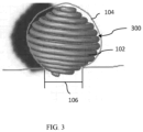
- FIG. 3 One example of a device that blocks the aneurysm neck 106 in a majority (or, in some cases, all) orientations is the embolic device 300 shown in FIG. 3 , which has a substantially spherical spiral shape.
- a geometric shape is described herein, in various embodiments, it includes a shape having all of its dimensions within 35% of a perfect geometric version of the shape, e.g., 25%, 10%, 5%, 2%, and/or 1%.
- the embolic device 300 can be deployed into the aneurysm 104 in any 360 degree orientation and still effectively block the neck 106 and also contact the interior wall (endothelium) of the aneurysm.
- the substantially spherical spiral shaped embolic device 300 can allow for continuous growth of tissue throughout the device 300.
- the embolic device 300 can provide a continuous path for tissue to grow within the aneurysm cavity, which can enable and/or accelerate healing of the aneurysm 104.
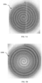
- Example dimensions of the embolic device 300 are shown in FIGS. 4A-4C .
- the primary diameter (see element 204 in FIG. 2 ) can be about 0.025 centimetres (0.010 inches).
- the height of the device (distance between top-most coil and bottom-most coil) can be about 3.1 mm.
- the diameter of the widest portion of the spherical spiral can be about 3.2 mm.
- the outer diameter of the bottom-most coil can be about 1.0 mm and the inner diameter of the bottom-most coil can be about 0.5 mm.
- the top-most coil can have similar dimensions to the bottom-most coil.
- embolic devices of the present invention can be formed from a flat sheet (e.g., formed from nitinol).
- the flat sheet can be formed into any suitable shape.
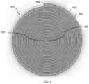
- FIGS. 5A-5B show top views of example embolic devices 500a, 500b formed from a flat sheet in a spiral shape.
- the spirals can take any suitable 3D shape, e.g., disc, sphere, semi-sphere (or partial sphere), cone, etc.
- the flat sheet can also have any desirable thickness, e.g., in a range from 0.00025 centimetres to 0.076 centimetres (0.0001" to 0.030"), in a range from 0.0013 centimetres to 0.069 centimetres (0.0005" to 0.027”), in a range from 0.0025 centimetres to 0.064 centimetres (0.001" to 0.025”), in a range from 0.0051 centimetres to 0.051 centimetres (0.002" to 0.020”), in a range from 0.0076 centimetres to 0.038 centimetres (0.003" to 0.015”), in a range from 0.010 centimetres to 0.025 centimetres (0.004" to 0.010”), in a range from 0.015 centimetres to 0.020 centimetres (0.006" to 0.008").
- any desirable thickness e.g., in a range from 0.00025 centimetres to 0.076 centimetre
- the flat sheet has a thickness in a range from 0.0051 centimetres to 0.010 centimetres (0.002" to 0.004").
- the width of the flat sheet has a constant width, as shown for example by the embolic device 500a in FIG. 5A .
- the width of the flat sheet has a drafted or tapered (e.g., decreasing or increasing) width, as shown for example by the embolic device 500b in FIG. 5B .
- an embolic device 600 can be formed by connecting two spiral elements 602, 604 at a connection region 606.
- the spiral elements 602, 604 can be formed from any suitable structure, e.g., microcoil, flat sheet (as shown in FIG. 6 ), thin film, etc.
- the connected spiral elements can form any 3D shape, e.g., disc, sphere, semi-sphere (or partial sphere), cone, etc. With reference to FIG. 6 , as one example, if an end point 608 of the first spiral element 602 is pulled out of the page, a cone shaped spiral is formed.
- spiral elements 602, 604 can be joined at the connection region 606 using any suitable technique, e.g., welding (e.g. laser, arc, resistance, friction stir), soldering, brazing, diffusion bonding, adhesive joining, and interconnect element (e.g., as described below), etc.
- welding e.g. laser, arc, resistance, friction stir
- soldering e.g., brazing, diffusion bonding, adhesive joining, and interconnect element (e.g., as described below), etc.
- both spiral elements 602, 604 can both be cut (e.g., laser cut) from a single piece of material (i.e., the spiral elements 602, 604 are of unitary construction with each other).
- an embolic device 700 can include alternating narrow portions 702 and link portions 704, as shown for example in FIG. 7 .
- the link portions 704 circumscribe an opening in at least one plane, e.g., the plane of the page, as shown in FIG. 7 .
- the link portions 704 can have any suitable shape, e.g., diamond-like (e.g., as shown in FIGS. 7 and 8 ), circular, rectangular, triangular, etc.
- the embolic device 700 can be formed from any suitable structure, e.g., a coil, a flat sheet, a thin film, combinations thereof, etc. For example, as shown in FIG.
- the narrow portions 702 can be formed of a single strip of flat sheet material (or multiple strips of flat sheet material with no opening in between) and the link portions 704 can be formed by at least two strips of flat sheet material that define a perimeter around or circumscribes an opening.
- the embolic device 700 can also have any desirable thickness, e.g., in a range from 0.00025 centimetres to 0.076 centimetres (0.0001" to 0.030"), in a range from 0.0013 centimetres to 0.069 centimetres (0.0005" to 0.027”), in a range from 0.0025 centimetres to 0.064 centimetres (0.001" to 0.025”), in a range from 0.0051 centimetres to 0.051 centimetres (0.002" to 0.020”), in a range from 0.0076 centimetres to 0.038 centimetres (0.003" to 0.015”), in a range from 0.010 centimetres to 0.025 centimetres (0.004" to 0.010”), in a range from 0.015 centimetres to 0.020 centimetres (0.006" to 0.008").
- the embolic device has a thickness in a range from 0.0051 centimetres to 0.076
- the narrow portions include coil segments 802.
- the coil segments 802 are disposed over another structure (e.g., a flat sheet, thin film, etc.). In other cases, the coil segments 802 are not disposed over another structure.
- the coil segments 802 can be attached to the link portions 704 using any known technique, e.g., melting a suture on the ends of each coil segment 802. Melting a suture on the ends of each coil segment 802 can also keep the coil segment 802 positioned between the link portions 704.
- the link portions 704 can be fixedly attached to proximate narrow portions and a strain relief element 804 can be used to relieve strain between the portions.
- the strain relief element can be formed of any suitable material, e.g., a suture material, a melted polymer (e.g., polypropylene, polyethylene, high density polyethylene, low density polyethylene, polyurethane, polyether block amide, polyamides, polymer adhesives, etc.), etc.
- a suture material e.g., polypropylene, polyethylene, high density polyethylene, low density polyethylene, polyurethane, polyether block amide, polyamides, polymer adhesives, etc.
- the embolic devices described herein can be introduced, delivered, positioned, and implanted within a vascular disorder using a microcatheter.
- the microcatheter can be a flexible, small diameter catheter having, for example, an inside diameter between 0.039 centimetres (0.015 inches) and 0.089 centimetres (0.035 inches) (e.g., between 0.041 centimetres (0.016 inches) and 0.053 centimetres (0.021 inches)).
- the microcatheter may be introduced by an introducer sheath/guiding catheter combination placed in the femoral artery or groin area of a patient.
- the microcatheter is guided into the vascular disorder with guidewires (e.g., long, torqueable proximal wire sections with more flexible distal wire sections designed to be advanced within tortuous vessels).
- guidewires e.g., long, torqueable proximal wire sections with more flexible distal wire sections designed to be advanced within tortuous vessels.
- Such guidewires may be visible using fluoroscopy and may be used to first access the vascular disorder, thereby allowing the microcatheter to be advanced over it into the disorder.
- the guidewire is removed from the catheter lumen.
- the embolic device may then be placed into the proximal open end of the microcatheter and advanced through the microcatheter with a delivery mechanism.
- the embolic device may attach to a delivery mechanism via any suitable structure, e.g., a loop 706 ( FIG. 7 ) on a proximal end of the device.
- a user e.g., a physician
- the embolic device Once the embolic device is satisfactorily positioned, it can be released into the disorder. Upon release, the device may form its deployed shape, for example the spiral shapes described above, or any other desired configuration. In some instances, the formation of the shape upon deployment into the vascular disorder is caused by the shape-memory nature of the material used to form the embolic device (e.g., nitinol).
- the material used to form the embolic device e.g., nitinol
- the embolic device are generally manufactured to have a particular shape in an unconstrained configuration, e.g., as the device would exist in packaging or an operating room before being delivered to a patient.
- the particular shape can include any of the embolic device shapes described herein.
- the embolic device is straightened out so that it can fit within and be delivered through a microcatheter (as described above). Once deployed out of the microcatheter to the vascular disorder, the embolic device can reform the shape it was manufactured to have (e.g., aided by a shape memory material). However, in some instances, the embolic device may not reform exactly into the shape it was manufactured to have, based on constraints imposed by the vascular disorder and other surrounding structures.
- the link portions 704 of the embolic device 700 shown in FIG. 7 can collapse (e.g., the openings can become narrower) when the embolic device 700 is located in a microcatheter during delivery.
- the link portions 704 can then expand (e.g., the openings can become wider) upon deployment of the embolic device to the vascular disorder.
- This can allow the embolic device 700 to be more easily delivered with less friction through a microcatheter, while also effectively blocking the neck of the aneurysm upon deployment.
- the coil segments 802 can further reduce friction of the embolic device during delivery through a microcatheter.
- the shape of the coil segments 802 can better match the shape of a lumen of the microcatheter.
- the coil segments 802 can increase the flexibility and malleability of the embolic device.
- the coil segments 802 can be formed of a material that generates less friction with the interior surface of the microcatheter.
- the coil segments 802 can also be formed of a radiopaque material (e.g., platinum) such that the embolic device can be viewed during delivery; for example, if the link portions 704 are formed from a non-radiopaque material.
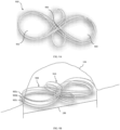
- the aneurysm 104 can be treated by an embolic device shaped to form at least one infinity shape portion, as shown for example in FIGS. 9A-9C .
- the term infinity shape refers to any shape formed by two loops (e.g., loops 902, 904) that cross at a common point (e.g., point 906), e.g., a figure eight shape, a lemniscate shape, etc. Notwithstanding any particular geometric or mathematic usages of the term infinity shape in other contexts, as defined herein, the two loops formed by the infinity shape can be of different sizes or the same size.
- the embolic device 900 can include multiple infinity shape portions 902a, 902b, 902c (see FIG. 9B ) stacked on top of each other, e.g., arranged to align with and overlay each other, or in some cases arranged circumferentially about an inner perimeter of the aneurysm (see FIG. 9C ).
- the embolic device 900 can include a first group of infinity shape portions 908 (which can include one or more infinity shape portions) arranged along a first axis and a second group of infinity shape portions 910 (which can include one or more infinity shape portions) rotated to be arranged at some angle (e.g., about 15°, about 30°, about 45°, about 60°, about 75°, and about 90°) with respect to the first axis.
- the second group of infinity shape portions can be arranged substantially perpendicular to the first axis.
- the infinity shape portions can be arranged substantially perpendicular to each other, in some instances, all of the infinity shape portions can be arranged along the same axis, e.g., aligned with each other. In other instances, only a single infinity shape portion is formed. Further, although in some instances the infinity shape portions block the neck 106 of the aneurysm, in other instances the infinity shape portion can be located in other portions of the aneurysm.
- the embolic device can form a series of infinity shape portions that, following deployment, can be arranged circumferentially about the interior perimeter of an aneurysm or other vascular disorder. Such an arrangement can contribute to framing the aneurysm.
- the infinity shape portions can also be arranged in other patterns. In general, any pattern can be used, including random patterns. Within such patterns, each infinity shape portion can be arranged at any rotational orientation and with any desirable overlap with respect to another infinity shape portion.
- multiple embolic devices can be joined with an interconnect element.
- the inventors have identified that when the portion of the device that fills the interior of the aneurysm cavity moves (e.g., to expand into apposition with an interior wall of the cavity) it can cause the portion of the device blocking the aneurysm neck to also move or shift, which can impact the effectiveness of the device in blocking the neck.
- the present invention includes a multi-stage embolic device that includes at least two embolic devices joined by an interconnect element that permits independent freedom of motion and/or relative positioning of each embolic device while they remain joined together.
- the multi-stage embolic device 1000 can include a first embolic device 1002 and a second embolic device 1004.
- the first embolic device 1002 is different from the second embolic device 1004.
- the first embolic device 1002 being different from the second embolic device 1004 means that they are two separate devices and not separate portions of a single device of unitary construction or monolithic construction.
- the first embolic device 1002 being different from the second embolic device 1004 means that the first embolic device 1002 is of non-unitary construction (or non-monolithic construction) with the second embolic device 1004. Said another way, the first embolic device 1002 is not integrally formed with the second embolic device 1004.
- the first embolic device 1002 being different from the second embolic device 1004 does not require that the devices 1002, 1004 have any other differences, although, in various instances, the devices 1002, 1004 can have other differences.
- the first and second embolic devices 1002, 1004 can have the same or different dimensions (length, inner diameter, outer diameter, etc.), the same or different stiffness, the same or different porosity, etc.
- the first embolic device can take any form; for example, the first embolic device 1002 can be a framing device that blocks the neck of the aneurysm. In various instances, the first embolic device 1002 can form any of the particular shapes described above, e.g., a spiral shape, an infinity shape, etc.
- the second embolic device 1004 can also take any form; for example, the second embolic device 1004 can be a filling device that fills the interior cavity of the aneurysm. In various instances, the second embolic device 1004 can form any of the particular shapes described above, e.g., spiral shape, an infinity shape, etc., or it can take a random or non-geometric shape. In various embodiments, the first embolic device 1002 and the second embolic device 1004 can be located at any location within or around the aneurysm 104, not just the locations shown in FIG. 10 .
- an interconnect element 1006 joins the embolic devices 1002, 1004 and can include any structure that permits independent freedom of motion and/or relative positioning of each embolic device while they remain joined together.
- independent freedom of motion means that the only constraint on the motion between the embolic devices is that they remain coupled. In various instances, any movement about a coupling point is possible.
- motion of the second embolic device 1004 within the aneurysm cavity does not necessarily result in a corresponding motion of the first embolic device 1002 blocking the neck of the aneurysm.
- permitting this freedom of motion represents an advantage of using an interconnect element to join two embolic devices, as opposed to using separate portions of a single coil (or other device) of unitary construction.
- the interconnect element 1006 can be located at any location within or around the aneurysm, depending on where it is advantageous to have independent freedom of motion between the devices, not just the location shown in FIG. 10 .
- the interconnect element can include two linked loops, a nitinol coil (in some cases covering another interconnect element, and in other cases by itself), a hook and loop scheme, a hinge, a suture element, a hole and loop, a ball and socket scheme, a pivot joint, a ball and pivot joint, a universal joint, a saddle joint, any mechanical articulating joint with one or more degrees of freedom, or combinations thereof.
- the interconnect element 1006 can be formed from certain portions of the first embolic device 1002 and the second embolic device 1004.
- one component of the interconnect element 1006 can be a loop formed at a distal or proximal end of the first embolic device 1002 (e.g., of unitary construction or integral with the first embolic device 1002) and another component of the interconnect element 1006 can be a loop formed at a distal or proximal end of the second embolic device 1004 (e.g., of unitary construction or integral with the second embolic device 1004).
- the interconnect element 1006 is not of unitary construction or integral with either the first embolic device 1002 or the second embolic device 1004 (i.e., the interconnect element is of non-unitary construction or of non-monolithic construction or non-integral with each of the first and second embolic devices 1002, 1004) and is, instead, fastened, adhered, and/or attached to the first and second embolic devices 1002, 1004.
- the interconnect element 1006 is of unitary construction or integral with one of the first and second embolic devices 1002, 1004, and of non-unitary construction or of non-monolithic construction or non-integral with the other embolic device.
- two of the first embolic device 1002, the second embolic device 1004, and the interconnect element 1006 are of non-unitary construction with each other.
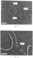
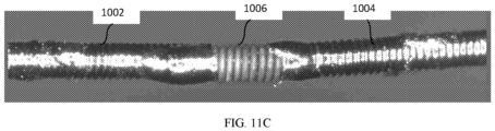
- FIGS. 11A-C are pictures showing different views of example interconnect elements 1006.
- FIGS. 11A-B depict an example interconnect element 1006 formed from two linked loops.
- FIG. 11C depicts an example interconnect element 1006 formed from two linked loops covered by a nitinol coil (e.g., a different coil than the first and second embolic devices 1002, 1004).
- the interconnect element 1006 can include a nitinol coil by itself not covering another interconnect element.
- the interconnect element 1006 includes a nitinol coil
- the nitinol coil is adhered to the first and second embolic devices 1002, 1004.
- the nitinol coil (or any other interconnect structure adhered to one or both of the embolic devices 1002, 1004) can be adhered to one or both of the embolic devices 1002, 1004 using any known technique.
- a desirable adhesion technique features adequate material biocompatibility and strength, while minimizing the length required to produce end-to-end fixation between the interconnect element 1006 and the embolic devices 1002, 1004 (which, in some cases, create lengths of unwanted stiffness).
- a solder e.g., gold, silver, or other desirable solder material
- Other example adhesion techniques include (but are not limited to) use of adhesives, welding (e.g., laser, arc, spot), brazing, diffusion bonding, etc.
- FIG. 12 is a picture showing an example multi-stage embolic device 1000 delivered within a model aneurysm 104.
- the interconnect element 1006 joins two elements that are delivered to the vascular disorder and intended to remain at the vascular disorder for a treatment period beyond the delivery. In such instances, the interconnect element 1006 does not join an embolic device to a device used for delivering the embolic device to the vascular disorder (e.g., a microcatheter or a delivery pusher).
- a device used for delivering the embolic device to the vascular disorder e.g., a microcatheter or a delivery pusher.
- more than two embolic devices can be joined together, for example, in parallel using more than one interconnect element.
- more than two embolic devices can be joined together in series using more than one interconnect element (e.g., up to one less than the number of embolic devices). Combinations of series and parallel arrangements are also contemplated. In general, any number of embolic devices can be joined, e.g., 2, 3, 4, 5, 10, etc. As shown in FIG.
- the embolic device 1000 can include a first embolic device 1002 joined in series to a second embolic device 1004 with a first interconnect element 1006a and the second embolic device 1004 joined in series to a third embolic device 1008 with a second interconnect element 1006b.
- the third embolic device 1008 can take any form (as can any additional embolic device).
- the third embolic device 1008 can be a finishing device that further fills the interior cavity of the aneurysm.
- the third embolic device 1008 (and any additional embolic device) can form any of the particular shapes described above, e.g., spiral shape, infinity shape, etc., or it can take a random or non-geometric shape.
- the third embolic device 1008 (and any additional embolic device) can be located in an any location within or around the aneurysm.
- each of the embolic devices can have different properties and behave differently from each other.
- any embolic device property can be variable amongst the embolic devices.
- some or all of the embolic devices can have different sizes, shapes, lengths, stiffness, porosity, etc.
- some of all of the embolic devices can have the same of some or all properties.
- This customizable and independent nature of the embolic device properties can enable operators (e.g., physicians) greater freedom to shape and control coil deployment and positioning than with conventional devices.
- an operator can deliver a coil such that it is initially positioned in a first direction and then pivots to be positioned in a different direction at an angle (e.g., 15°, 30°, 45°, 60°, 75°, 90°, etc.) to the first direction.
- an angle e.g., 15°, 30°, 45°, 60°, 75°, 90°, etc.
- the embolic devices described herein can include a structure (e.g., microcoil, flat sheet, thin film, etc.) covered by a cover element or not covered by a cover element.
- a structure e.g., microcoil, flat sheet, thin film, etc.
- any, none, or all of the individual embolic devices e.g., 1002, 1004, 1008, etc.
Landscapes
- Health & Medical Sciences (AREA)
- Life Sciences & Earth Sciences (AREA)
- Surgery (AREA)
- Animal Behavior & Ethology (AREA)
- Veterinary Medicine (AREA)
- Vascular Medicine (AREA)
- Public Health (AREA)
- Engineering & Computer Science (AREA)
- Biomedical Technology (AREA)
- Heart & Thoracic Surgery (AREA)
- General Health & Medical Sciences (AREA)
- Molecular Biology (AREA)
- Medical Informatics (AREA)
- Nuclear Medicine, Radiotherapy & Molecular Imaging (AREA)
- Reproductive Health (AREA)
- Neurosurgery (AREA)
- Surgical Instruments (AREA)
- Cardiology (AREA)
- Oral & Maxillofacial Surgery (AREA)
- Transplantation (AREA)
Claims (12)
- Mehrstufige Embolievorrichtung (1000) zur Verwendung beim Behandeln einer Gefäßstörung, wobei die mehrstufige Embolievorrichtung Folgendes umfasst:eine erste Embolievorrichtung (1002);eine zweite Embolievorrichtung (1004), die sich von der ersten Embolievorrichtung (1002) unterscheidet;ein Klettverbindungselement (1006), das die erste (1002) und die zweite (1004) Embolievorrichtung zusammenfügt und eine relative Positionierung jeder Embolievorrichtung (1002, 1004) ermöglicht, während sie zusammengefügt bleiben; undeine Nitinolspirale, die über dem Klettverbindungselement (1006) angeordnet und mit der ersten Embolievorrichtung (1002) und der zweiten (1004) Embolievorrichtung verklebt ist,wobei mindestens eine von der ersten (1002) und der zweiten (1004) Embolievorrichtung eine Reihe von abwechselnden schmalen Abschnitten (702) und Verbindungsgliedabschnitten (704) umfasst, wobei jeder Verbindungsgliedabschnitt (704) eine Öffnung in mindestens einer Ebene umgibt, undwobei jede von der ersten Embolievorrichtung (1002) und der zweiten Embolievorrichtung (1004) mindestens eines von einer Spirale, einer flachen Platte, einer dünnen Folie oder Kombinationen davon umfasst.
- Mehrstufige Embolievorrichtung (1000) nach Anspruch 1, wobei mindestens eine von der ersten (1002) und der zweiten (1004) Embolievorrichtung ein Material umfasst, das ausgewählt ist aus der Gruppe bestehend aus Platin, Nitinol, Legierungen davon und Kombinationen davon.
- Mehrstufige Embolievorrichtung (1000) nach Anspruch 1, wobei mindestens eine von der ersten (1002) und der zweiten (1004) Embolievorrichtung eine Dicke in einem Bereich von 0,00127 Zentimetern bis 0,06858 Zentimetern umfasst.
- Mehrstufige Embolievorrichtung (1000) nach Anspruch 1, wobei mindestens ein Abschnitt der mehrstufigen Embolievorrichtung (1000) strahlenundurchlässig ist.
- Mehrstufige Embolievorrichtung (1000) nach Anspruch 1, wobei mindestens eine von der ersten (1002) und der zweiten (1004) Embolievorrichtung eine flexible Struktur umfasst, welche die Reihe von abwechselnden schmalen Abschnitten (702) und Verbindungsgliedabschnitten (704) umfasst, wobei jeder schmale Abschnitt (702) fest an nahen Verbindungsgliedabschnitten (704) angebracht ist, und ferner umfassend:
ein Zugentlastungselement (804) zwischen jedem schmalen Abschnitt (702) und den nahen Verbindungsgliedabschnitten (704). - Mehrstufige Embolievorrichtung (1000) nach Anspruch 5, wobei das Zugentlastungselement (804) aus mindestens einem von einem geschmolzenem Nahtmaterial oder einem geschmolzenen Polymer ausgebildet ist.
- Mehrstufige Embolievorrichtung (1000) nach Anspruch 1, wobei mindestens eine von der ersten (1002) und der zweiten (1004) Embolievorrichtung eine flexible Struktur umfasst, welche die Reihe von abwechselnden schmalen Abschnitten (702) und Verbindungsgliedabschnitten (704) umfasst, wobei jeder Verbindungsgliedabschnitt eine rautenförmige Form umfasst.
- Mehrstufige Embolievorrichtung (1000) nach Anspruch 1, wobei mindestens eine von der ersten (1002) und der zweiten (1004) Embolievorrichtung eine flexible Struktur umfasst, welche die Reihe von abwechselnden schmalen Abschnitten (702) und Verbindungsgliedabschnitten (704) umfasst, wobei jeder Verbindungsgliedabschnitt (704) dazu ausgelegt ist, sich zusammenzudrücken, wenn die mehrstufige Embolievorrichtung (1000) innerhalb eines Mikrokatheters angeordnet wird.
- Mehrstufige Embolievorrichtung (1000) nach Anspruch 8, wobei jeder Verbindungsgliedabschnitt (704) ferner dazu ausgelegt ist, sich bei Ausfahren der mehrstufigen Embolievorrichtung (1000) aus dem Mikrokatheter auszudehnen.
- Mehrstufige Embolievorrichtung (1000) nach Anspruch 1, wobei mindestens eine von der ersten (1002) und der zweiten (1004) Embolievorrichtung eine flexible Struktur umfasst, welche die Reihe von abwechselnden schmalen Abschnitten (702) und Verbindungsgliedabschnitten (704) umfasst, wobei sich die schmalen Abschnitte (702) und die Verbindungsgliedabschnitte (704) in gleichmäßigen Abständen abwechseln.
- Mehrstufige Embolievorrichtung (1000) nach Anspruch 1, wobei mindestens eine von der ersten (1002) und der zweiten (1004) Embolievorrichtung eine flexible Struktur umfasst, welche die Reihe von abwechselnden schmalen Abschnitten (702) und Verbindungsgliedabschnitten (704) umfasst, wobei sich die schmalen Abschnitte (702) und die Verbindungsgliedabschnitte (704) in ungleichmäßigen Abständen abwechseln.
- Mehrstufige Embolievorrichtung (1000) nach Anspruch 1, wobei die erste Embolievorrichtung (1002) und die zweite Embolievorrichtung (1004) hintereinander angebracht sind.
Applications Claiming Priority (2)
| Application Number | Priority Date | Filing Date | Title |
|---|---|---|---|
| US201862652441P | 2018-04-04 | 2018-04-04 | |
| PCT/US2019/025770 WO2019195540A2 (en) | 2018-04-04 | 2019-04-04 | Embolic device with improved neck coverage |
Publications (2)
| Publication Number | Publication Date |
|---|---|
| EP3773252A2 EP3773252A2 (de) | 2021-02-17 |
| EP3773252B1 true EP3773252B1 (de) | 2025-06-04 |
Family
ID=66484123
Family Applications (1)
| Application Number | Title | Priority Date | Filing Date |
|---|---|---|---|
| EP19723527.8A Active EP3773252B1 (de) | 2018-04-04 | 2019-04-04 | Embolievorrichtung mit verbesserter halsabdeckung |
Country Status (6)
| Country | Link |
|---|---|
| US (1) | US11819215B2 (de) |
| EP (1) | EP3773252B1 (de) |
| JP (2) | JP2021520255A (de) |
| CN (1) | CN112153946B (de) |
| ES (1) | ES3035267T3 (de) |
| WO (1) | WO2019195540A2 (de) |
Families Citing this family (11)
| Publication number | Priority date | Publication date | Assignee | Title |
|---|---|---|---|---|
| US11357511B2 (en) | 2008-05-01 | 2022-06-14 | Aneuclose Llc | Intrasacular aneurysm occlusion device with globular first configuration and bowl-shaped second configuration |
| US11471164B2 (en) | 2008-05-01 | 2022-10-18 | Aneuclose Llc | Methods of occluding a cerebral aneurysm by inserting embolic members or material into an intrasacular implant |
| US11471163B2 (en) | 2008-05-01 | 2022-10-18 | Aneuclose Llc | Intrasaccular aneurysm occlusion device with net or mesh expanded by string-of-pearls embolies |
| US11464518B2 (en) | 2008-05-01 | 2022-10-11 | Aneuclose Llc | Proximal concave neck bridge with central lumen and distal net for occluding cerebral aneurysms |
| US11484322B2 (en) | 2018-01-03 | 2022-11-01 | Aneuclose Llc | Aneurysm neck bridge with a closeable opening or lumen through which embolic material is inserted into the aneurysm sac |
| US11583289B2 (en) | 2008-05-01 | 2023-02-21 | Aneuclose Llc | Aneurysm-occluding mesh ribbon with a series of loops or segments having distal-to-proximal variation in size, shape, and/or orientation |
| CN114098878B (zh) * | 2020-08-31 | 2024-02-20 | 微创神通医疗科技(上海)有限公司 | 血管瘤封堵装置、血管瘤封堵治疗装置和血管瘤封堵系统 |
| JP2024530752A (ja) * | 2021-08-31 | 2024-08-23 | インキュメデックス インコーポレイテッド | 改良された縮径部被覆を伴う塞栓デバイス |
| CN113855145B (zh) * | 2021-10-29 | 2023-06-30 | 微创神通医疗科技(上海)有限公司 | 血管瘤封堵装置、血管瘤封堵治疗装置和血管瘤封堵系统 |
| WO2024147031A1 (en) * | 2023-01-08 | 2024-07-11 | Yousefiroshan Hamed | A novel device design and true mockup to treat intracranial aneurysms |
| US20250057540A1 (en) * | 2023-08-18 | 2025-02-20 | Ndi Tip Teknolojileri Anonim Sirket | Embolic coil, system, and method for making multiple self-adaptive loops with improved anchoring and filling |
Citations (1)
| Publication number | Priority date | Publication date | Assignee | Title |
|---|---|---|---|---|
| US20180049859A1 (en) * | 2016-08-16 | 2018-02-22 | Spartan Micro, Inc. | Intravascular flow diversion devices |
Family Cites Families (86)
| Publication number | Priority date | Publication date | Assignee | Title |
|---|---|---|---|---|
| US5853418A (en) | 1995-06-30 | 1998-12-29 | Target Therapeutics, Inc. | Stretch resistant vaso-occlusive coils (II) |
| US5769884A (en) | 1996-06-27 | 1998-06-23 | Cordis Corporation | Controlled porosity endovascular implant |
| EP1011532B1 (de) | 1997-04-23 | 2014-05-07 | Ethicon Endo-Surgery, Inc. | Abzweigender stent und distales schutzsystem |
| US5935148A (en) * | 1998-06-24 | 1999-08-10 | Target Therapeutics, Inc. | Detachable, varying flexibility, aneurysm neck bridge |
| US6755856B2 (en) | 1998-09-05 | 2004-06-29 | Abbott Laboratories Vascular Enterprises Limited | Methods and apparatus for stenting comprising enhanced embolic protection, coupled with improved protection against restenosis and thrombus formation |
| US6602261B2 (en) * | 1999-10-04 | 2003-08-05 | Microvention, Inc. | Filamentous embolic device with expansile elements |
| US6342063B1 (en) | 2000-01-26 | 2002-01-29 | Scimed Life Systems, Inc. | Device and method for selectively removing a thrombus filter |
| US6530934B1 (en) * | 2000-06-06 | 2003-03-11 | Sarcos Lc | Embolic device composed of a linear sequence of miniature beads |
| US6603994B2 (en) * | 2000-12-28 | 2003-08-05 | Scimed Life Systems, Inc. | Apparatus and method for internally inducing a magnetic field in an aneurysm to embolize aneurysm with magnetically-controllable substance |
| ATE516759T1 (de) | 2001-05-29 | 2011-08-15 | Microvention Inc | Verfahren zur herstellung von expandierbaren filamentösen embolisierungsvorrichtungen |
| CA2452953A1 (en) | 2001-07-18 | 2003-01-30 | The Research Foundation Of State University Of New York | Stent vascular intervention device and method |
| KR100947468B1 (ko) | 2001-07-26 | 2010-03-17 | 쿠크 바이오텍, 인코포레이티드 | 혈관 폐쇄 부재 및 전달 장치 |
| US6802851B2 (en) * | 2001-09-20 | 2004-10-12 | Gordia Neurovascular, Inc. | Stent aneurysm embolization method using collapsible member and embolic coils |
| US8262689B2 (en) | 2001-09-28 | 2012-09-11 | Advanced Cardiovascular Systems, Inc. | Embolic filtering devices |
| US20030199887A1 (en) * | 2002-04-23 | 2003-10-23 | David Ferrera | Filamentous embolization device and method of use |
| EP1684666A4 (de) | 2003-10-14 | 2010-04-07 | James C Peacock Iii | Aneurysma-behandlungssystem und verfahren |
| WO2005042081A1 (en) | 2003-10-28 | 2005-05-12 | Peacock James C Iii | Embolic filter device and related systems and methods |
| US7763011B2 (en) | 2003-12-22 | 2010-07-27 | Boston Scientific Scimed, Inc. | Variable density braid stent |
| US8500751B2 (en) | 2004-03-31 | 2013-08-06 | Merlin Md Pte Ltd | Medical device |
| AU2010236494B2 (en) | 2004-05-25 | 2013-05-30 | Covidien Lp | Vascular stenting for aneurysms |
| US9675476B2 (en) | 2004-05-25 | 2017-06-13 | Covidien Lp | Vascular stenting for aneurysms |
| US20050267510A1 (en) * | 2004-05-26 | 2005-12-01 | Nasser Razack | Device for the endovascular treatment of intracranial aneurysms |
| US20050283220A1 (en) | 2004-06-22 | 2005-12-22 | Gobran Riad H | Blood flow diverters for the treatment of intracranial aneurysms |
| US7875044B2 (en) | 2004-10-15 | 2011-01-25 | Codman & Shurtleff, Inc. | Remodeling device for aneurysms |
| US7608089B2 (en) * | 2004-12-22 | 2009-10-27 | Boston Scientific Scimed, Inc. | Vaso-occlusive device having pivotable coupling |
| US20080147111A1 (en) * | 2005-01-03 | 2008-06-19 | Eric Johnson | Endoluminal Filter With Fixation |
| US20060178696A1 (en) | 2005-02-04 | 2006-08-10 | Porter Stephen C | Macroporous materials for use in aneurysms |
| US20060271097A1 (en) | 2005-05-31 | 2006-11-30 | Kamal Ramzipoor | Electrolytically detachable implantable devices |
| WO2007002933A2 (en) | 2005-06-28 | 2007-01-04 | Stout Medical Group, Inc. | Micro-thin film structures for cardiovascular indications |
| US20070021816A1 (en) | 2005-07-21 | 2007-01-25 | The Research Foundation Of State University Of New York | Stent vascular intervention device and methods for treating aneurysms |
| JP2009513288A (ja) | 2005-10-27 | 2009-04-02 | エヌフォーカス ニューロメディカル, インコーポレイテッド | 部分的に覆われたステント機器とその使用方法 |
| US20070142859A1 (en) | 2005-12-19 | 2007-06-21 | Boston Scientific Scimed, Inc. | Embolic coils |
| CA2654261C (en) * | 2006-05-19 | 2017-05-16 | Mako Surgical Corp. | Method and apparatus for controlling a haptic device |
| US20070299461A1 (en) | 2006-06-21 | 2007-12-27 | Boston Scientific Scimed, Inc. | Embolic coils and related components, systems, and methods |
| US9339367B2 (en) | 2006-09-11 | 2016-05-17 | Edwards Lifesciences Ag | Embolic deflection device |
| WO2008064206A2 (en) | 2006-11-20 | 2008-05-29 | Boston Scientific Scimed, Inc. | Mechanically detachable vaso-occlusive device |
| US8636791B1 (en) | 2006-11-21 | 2014-01-28 | Seshadri Raju | Venous stent |
| US20080281350A1 (en) | 2006-12-13 | 2008-11-13 | Biomerix Corporation | Aneurysm Occlusion Devices |
| US20090112251A1 (en) * | 2007-07-25 | 2009-04-30 | Aga Medical Corporation | Braided occlusion device having repeating expanded volume segments separated by articulation segments |
| US8361138B2 (en) * | 2007-07-25 | 2013-01-29 | Aga Medical Corporation | Braided occlusion device having repeating expanded volume segments separated by articulation segments |
| US10813779B2 (en) * | 2008-04-25 | 2020-10-27 | CARDINAL HEALTH SWITZERLAND 515 GmbH | Stent attachment and deployment mechanism |
| US20160374690A9 (en) * | 2010-10-21 | 2016-12-29 | Robert A. Connor | Devices and Methods for Occluding a Cerebral Aneurysm |
| US9179918B2 (en) * | 2008-07-22 | 2015-11-10 | Covidien Lp | Vascular remodeling device |
| KR101652804B1 (ko) | 2008-09-05 | 2016-08-31 | 펄사 배스큘라, 아이엔씨. | 생리적 구멍 또는 공동을 지지하거나 또는 폐쇄하기 위한 시스템과 방법 |
| EP2421482B1 (de) | 2009-04-20 | 2019-11-13 | Achieva Medical Limited | Ausgabevorrichtung für eine abdichtungsvorrichtung mit einem mechanischen vernetzungs- und kopplungsmechanismus |
| US20110054515A1 (en) | 2009-08-25 | 2011-03-03 | John Bridgeman | Device and method for occluding the left atrial appendage |
| EP3305214A3 (de) | 2009-09-04 | 2018-07-04 | Pulsar Vascular, Inc. | Systeme zum einschliessen einer anatomischen öffnung |
| US9095342B2 (en) | 2009-11-09 | 2015-08-04 | Covidien Lp | Braid ball embolic device features |
| US9358140B1 (en) | 2009-11-18 | 2016-06-07 | Aneuclose Llc | Stent with outer member to embolize an aneurysm |
| US8568471B2 (en) * | 2010-01-30 | 2013-10-29 | Abbott Cardiovascular Systems Inc. | Crush recoverable polymer scaffolds |
| US8425548B2 (en) | 2010-07-01 | 2013-04-23 | Aneaclose LLC | Occluding member expansion and then stent expansion for aneurysm treatment |
| DE102010027106A1 (de) | 2010-07-14 | 2012-01-19 | Siemens Aktiengesellschaft | Flow Diverter |
| US10010327B2 (en) * | 2010-12-16 | 2018-07-03 | Lawrence Livermore National Security, Llc | Expandable implant and implant system |
| US20120245614A1 (en) * | 2011-03-21 | 2012-09-27 | William Joseph Drasler | Branch and Truncal Vessel Occluder |
| EP2716263B1 (de) | 2011-05-26 | 2016-12-14 | Dongguk University Industry-Academic Cooperation Foundation | Stent zur spulenembolisierung eines hirnaneurysmas |
| US10624647B2 (en) | 2011-06-03 | 2020-04-21 | Pulsar Vascular, Inc. | Aneurysm devices with additional anchoring mechanisms and associated systems and methods |
| US8696731B2 (en) * | 2011-06-10 | 2014-04-15 | DePuy Synthes Products, LLC | Lock/floating marker band on pusher wire for self-expanding stents or medical devices |
| US9119625B2 (en) | 2011-10-05 | 2015-09-01 | Pulsar Vascular, Inc. | Devices, systems and methods for enclosing an anatomical opening |
| US20130123901A1 (en) | 2011-11-14 | 2013-05-16 | Robert A. Connor | Stent with in situ determination of wall areas with differences in porosity |
| EP2785261A4 (de) | 2011-12-02 | 2015-10-07 | Inceptus Medical LLC | Embolieschutzvorrichtung und verfahren zu ihrer anwendung |
| CA2862232C (en) * | 2012-01-17 | 2019-09-24 | Endoshape, Inc. | Occlusion device for a vascular or biological lumen |
| WO2013128381A1 (en) | 2012-02-28 | 2013-09-06 | Ben Gurion University Of The Negev Research And Development Authority | Combined therapy of alpha-1-antitrypsin and temporal t-cell depletion for preventing graft rejection |
| US9155540B2 (en) | 2012-03-30 | 2015-10-13 | DePuy Synthes Products, Inc. | Embolic coil detachment mechanism with heating element and kicker |
| WO2013166475A1 (en) * | 2012-05-04 | 2013-11-07 | Interventco Llc | Device and method for filling of aneurysm or body cavity |
| CN104736071B (zh) * | 2012-08-22 | 2018-09-28 | 菲诺克斯有限公司 | 植入物 |
| WO2014128313A1 (es) * | 2013-02-21 | 2014-08-28 | Castaño Duque Carlos | Dispositivo de soporte y colocación de elementos oclusivos |
| US20140277397A1 (en) | 2013-03-12 | 2014-09-18 | DePuy Synthes Products, LLC | Variable porosity intravascular implant and manufacturing method |
| US9907684B2 (en) | 2013-05-08 | 2018-03-06 | Aneuclose Llc | Method of radially-asymmetric stent expansion |
| US9737306B2 (en) | 2013-06-14 | 2017-08-22 | Artventive Medical Group, Inc. | Implantable luminal devices |
| GB2516423B (en) | 2013-07-10 | 2015-07-15 | Cook Medical Technologies Llc | Vascular closure device |
| MX2016000653A (es) | 2013-07-17 | 2017-05-04 | Lake Region Mfg Inc D/B/A Lake Region Medical | Dispositivo de proteccion contra embolia de alto flujo. |
| US9636118B2 (en) * | 2014-02-27 | 2017-05-02 | Incumedx, Inc. | Embolic framing microcoils |
| US20150327868A1 (en) | 2014-05-13 | 2015-11-19 | Ndi Tip Teknolojileri Anonim Sirketi | Retractable and rapid disconnect, floating diameter embolic coil product and delivery system |
| CN203885667U (zh) | 2014-06-06 | 2014-10-22 | 微创神通医疗科技(上海)有限公司 | 一种支架 |
| CA2955953A1 (en) | 2014-07-25 | 2016-01-28 | Incumedx, Inc. | Covered embolic coils |
| US10595875B2 (en) | 2014-12-31 | 2020-03-24 | Endostream Medical Ltd. | Device for restricting blood flow to aneurysms |
| JP6549717B2 (ja) | 2015-01-12 | 2019-07-24 | マイクロベンション インコーポレイテッドMicrovention, Inc. | ステント |
| US20170042551A1 (en) | 2015-08-13 | 2017-02-16 | The Brain Protection Company PTY LTD | Implantable damping devices for treating dementia and associated systems and methods of use |
| US10314593B2 (en) | 2015-09-23 | 2019-06-11 | Covidien Lp | Occlusive devices |
| WO2017106567A1 (en) | 2015-12-15 | 2017-06-22 | Nsvascular, Inc. | Intrasaccular thin-film flow diverters and related methods |
| CN205729568U (zh) * | 2016-01-29 | 2016-11-30 | 深圳迈德科技有限公司 | 腔静脉过滤器 |
| EP3413808B1 (de) * | 2016-02-10 | 2023-07-26 | Microvention, Inc. | Vorrichtungen zur vaskularen okklusion |
| US10813644B2 (en) * | 2016-04-01 | 2020-10-27 | Artventive Medical Group, Inc. | Occlusive implant and delivery system |
| CN113180882B (zh) * | 2016-06-21 | 2024-05-24 | 内流医疗有限公司 | 用于治疗血管畸形部的装置及试剂盒 |
| CN206651896U (zh) * | 2016-12-16 | 2017-11-21 | 中国人民解放军第四军医大学 | 一种用于下腔静脉阻塞治疗的支架 |
| CN106491174A (zh) | 2016-12-20 | 2017-03-15 | 北京久事神康医疗科技有限公司 | 一种可回收的血流导向装置 |
-
2019
- 2019-04-04 EP EP19723527.8A patent/EP3773252B1/de active Active
- 2019-04-04 CN CN201980033335.4A patent/CN112153946B/zh active Active
- 2019-04-04 WO PCT/US2019/025770 patent/WO2019195540A2/en not_active Ceased
- 2019-04-04 JP JP2020554276A patent/JP2021520255A/ja active Pending
- 2019-04-04 US US16/375,516 patent/US11819215B2/en active Active
- 2019-04-04 ES ES19723527T patent/ES3035267T3/es active Active
-
2023
- 2023-08-18 JP JP2023133402A patent/JP7669433B2/ja active Active
Patent Citations (1)
| Publication number | Priority date | Publication date | Assignee | Title |
|---|---|---|---|---|
| US20180049859A1 (en) * | 2016-08-16 | 2018-02-22 | Spartan Micro, Inc. | Intravascular flow diversion devices |
Also Published As
| Publication number | Publication date |
|---|---|
| ES3035267T3 (en) | 2025-09-01 |
| CN112153946B (zh) | 2024-05-28 |
| JP2021520255A (ja) | 2021-08-19 |
| WO2019195540A3 (en) | 2019-11-21 |
| CN112153946A (zh) | 2020-12-29 |
| US20190307546A1 (en) | 2019-10-10 |
| EP3773252A2 (de) | 2021-02-17 |
| JP7669433B2 (ja) | 2025-04-28 |
| WO2019195540A2 (en) | 2019-10-10 |
| US11819215B2 (en) | 2023-11-21 |
| JP2023144097A (ja) | 2023-10-06 |
Similar Documents
| Publication | Publication Date | Title |
|---|---|---|
| EP3773252B1 (de) | Embolievorrichtung mit verbesserter halsabdeckung | |
| US11911040B2 (en) | Flow attenuation device | |
| JP7584549B2 (ja) | 閉塞デバイス | |
| EP3318224B1 (de) | Stenteinführungssystem, zugehörige strömungsumleitungsvorrichtung und montageverfahren der strömungsumleitungsvorrichtung | |
| US8444668B2 (en) | Expandable vascular occlusion device | |
| CN101415380B (zh) | 动脉瘤阻塞装置 | |
| CN104582634B (zh) | 动脉瘤闭塞系统和方法 | |
| CN114025692A (zh) | 用于治疗动脉瘤的系统和方法 | |
| US20230225737A1 (en) | Vascular occlusion devices utilizing thin film nitinol foils | |
| TW202027685A (zh) | 用於栓塞編織物之螺線輸送系統 | |
| JP2008502378A (ja) | フレキシブルな血管閉鎖デバイス | |
| US20250268599A9 (en) | Systems and methods for treating aneurysms | |
| JP2022065652A (ja) | 反転編組動脈瘤治療システム及び方法 | |
| CN118055733A (zh) | 具有改进的颈部覆盖的栓塞装置 | |
| JP2025536000A (ja) | 脈管異常の治療用デバイス | |
| HK1129558B (en) | An aneurysm occlusion device |
Legal Events
| Date | Code | Title | Description |
|---|---|---|---|
| STAA | Information on the status of an ep patent application or granted ep patent |
Free format text: STATUS: UNKNOWN |
|
| STAA | Information on the status of an ep patent application or granted ep patent |
Free format text: STATUS: THE INTERNATIONAL PUBLICATION HAS BEEN MADE |
|
| PUAI | Public reference made under article 153(3) epc to a published international application that has entered the european phase |
Free format text: ORIGINAL CODE: 0009012 |
|
| STAA | Information on the status of an ep patent application or granted ep patent |
Free format text: STATUS: REQUEST FOR EXAMINATION WAS MADE |
|
| 17P | Request for examination filed |
Effective date: 20200929 |
|
| AK | Designated contracting states |
Kind code of ref document: A2 Designated state(s): AL AT BE BG CH CY CZ DE DK EE ES FI FR GB GR HR HU IE IS IT LI LT LU LV MC MK MT NL NO PL PT RO RS SE SI SK SM TR |
|
| AX | Request for extension of the european patent |
Extension state: BA ME |
|
| DAV | Request for validation of the european patent (deleted) | ||
| DAX | Request for extension of the european patent (deleted) | ||
| REG | Reference to a national code |
Ref country code: HK Ref legal event code: DE Ref document number: 40047967 Country of ref document: HK |
|
| STAA | Information on the status of an ep patent application or granted ep patent |
Free format text: STATUS: EXAMINATION IS IN PROGRESS |
|
| P01 | Opt-out of the competence of the unified patent court (upc) registered |
Effective date: 20230509 |
|
| 17Q | First examination report despatched |
Effective date: 20230531 |
|
| GRAP | Despatch of communication of intention to grant a patent |
Free format text: ORIGINAL CODE: EPIDOSNIGR1 |
|
| STAA | Information on the status of an ep patent application or granted ep patent |
Free format text: STATUS: GRANT OF PATENT IS INTENDED |
|
| RIC1 | Information provided on ipc code assigned before grant |
Ipc: A61B 17/00 20060101ALN20240613BHEP Ipc: A61B 17/12 20060101AFI20240613BHEP |
|
| INTG | Intention to grant announced |
Effective date: 20240625 |
|
| RAP3 | Party data changed (applicant data changed or rights of an application transferred) |
Owner name: INCUMEDX INC. |
|
| GRAS | Grant fee paid |
Free format text: ORIGINAL CODE: EPIDOSNIGR3 |
|
| GRAA | (expected) grant |
Free format text: ORIGINAL CODE: 0009210 |
|
| STAA | Information on the status of an ep patent application or granted ep patent |
Free format text: STATUS: THE PATENT HAS BEEN GRANTED |
|
| AK | Designated contracting states |
Kind code of ref document: B1 Designated state(s): AL AT BE BG CH CY CZ DE DK EE ES FI FR GB GR HR HU IE IS IT LI LT LU LV MC MK MT NL NO PL PT RO RS SE SI SK SM TR |
|
| REG | Reference to a national code |
Ref country code: GB Ref legal event code: FG4D |
|
| REG | Reference to a national code |
Ref country code: CH Ref legal event code: EP |
|
| REG | Reference to a national code |
Ref country code: DE Ref legal event code: R096 Ref document number: 602019070735 Country of ref document: DE |
|
| REG | Reference to a national code |
Ref country code: IE Ref legal event code: FG4D |
|
| REG | Reference to a national code |
Ref country code: ES Ref legal event code: FG2A Ref document number: 3035267 Country of ref document: ES Kind code of ref document: T3 Effective date: 20250901 |
|
| REG | Reference to a national code |
Ref country code: NL Ref legal event code: MP Effective date: 20250604 |
|
| PG25 | Lapsed in a contracting state [announced via postgrant information from national office to epo] |
Ref country code: FI Free format text: LAPSE BECAUSE OF FAILURE TO SUBMIT A TRANSLATION OF THE DESCRIPTION OR TO PAY THE FEE WITHIN THE PRESCRIBED TIME-LIMIT Effective date: 20250604 |
|
| REG | Reference to a national code |
Ref country code: LT Ref legal event code: MG9D |
|
| PG25 | Lapsed in a contracting state [announced via postgrant information from national office to epo] |
Ref country code: GR Free format text: LAPSE BECAUSE OF FAILURE TO SUBMIT A TRANSLATION OF THE DESCRIPTION OR TO PAY THE FEE WITHIN THE PRESCRIBED TIME-LIMIT Effective date: 20250905 Ref country code: NO Free format text: LAPSE BECAUSE OF FAILURE TO SUBMIT A TRANSLATION OF THE DESCRIPTION OR TO PAY THE FEE WITHIN THE PRESCRIBED TIME-LIMIT Effective date: 20250904 |
|
| PG25 | Lapsed in a contracting state [announced via postgrant information from national office to epo] |
Ref country code: PL Free format text: LAPSE BECAUSE OF FAILURE TO SUBMIT A TRANSLATION OF THE DESCRIPTION OR TO PAY THE FEE WITHIN THE PRESCRIBED TIME-LIMIT Effective date: 20250604 |
|
| PG25 | Lapsed in a contracting state [announced via postgrant information from national office to epo] |
Ref country code: BG Free format text: LAPSE BECAUSE OF FAILURE TO SUBMIT A TRANSLATION OF THE DESCRIPTION OR TO PAY THE FEE WITHIN THE PRESCRIBED TIME-LIMIT Effective date: 20250604 |
|
| PG25 | Lapsed in a contracting state [announced via postgrant information from national office to epo] |
Ref country code: HR Free format text: LAPSE BECAUSE OF FAILURE TO SUBMIT A TRANSLATION OF THE DESCRIPTION OR TO PAY THE FEE WITHIN THE PRESCRIBED TIME-LIMIT Effective date: 20250604 |
|
| PG25 | Lapsed in a contracting state [announced via postgrant information from national office to epo] |
Ref country code: RS Free format text: LAPSE BECAUSE OF FAILURE TO SUBMIT A TRANSLATION OF THE DESCRIPTION OR TO PAY THE FEE WITHIN THE PRESCRIBED TIME-LIMIT Effective date: 20250904 |
|
| PG25 | Lapsed in a contracting state [announced via postgrant information from national office to epo] |
Ref country code: LV Free format text: LAPSE BECAUSE OF FAILURE TO SUBMIT A TRANSLATION OF THE DESCRIPTION OR TO PAY THE FEE WITHIN THE PRESCRIBED TIME-LIMIT Effective date: 20250604 |
|
| PG25 | Lapsed in a contracting state [announced via postgrant information from national office to epo] |
Ref country code: NL Free format text: LAPSE BECAUSE OF FAILURE TO SUBMIT A TRANSLATION OF THE DESCRIPTION OR TO PAY THE FEE WITHIN THE PRESCRIBED TIME-LIMIT Effective date: 20250604 |
|
| PG25 | Lapsed in a contracting state [announced via postgrant information from national office to epo] |
Ref country code: PT Free format text: LAPSE BECAUSE OF FAILURE TO SUBMIT A TRANSLATION OF THE DESCRIPTION OR TO PAY THE FEE WITHIN THE PRESCRIBED TIME-LIMIT Effective date: 20251006 |
|
| REG | Reference to a national code |
Ref country code: AT Ref legal event code: MK05 Ref document number: 1799593 Country of ref document: AT Kind code of ref document: T Effective date: 20250604 |
|
| PG25 | Lapsed in a contracting state [announced via postgrant information from national office to epo] |
Ref country code: IS Free format text: LAPSE BECAUSE OF FAILURE TO SUBMIT A TRANSLATION OF THE DESCRIPTION OR TO PAY THE FEE WITHIN THE PRESCRIBED TIME-LIMIT Effective date: 20251004 |
|
| PG25 | Lapsed in a contracting state [announced via postgrant information from national office to epo] |
Ref country code: SM Free format text: LAPSE BECAUSE OF FAILURE TO SUBMIT A TRANSLATION OF THE DESCRIPTION OR TO PAY THE FEE WITHIN THE PRESCRIBED TIME-LIMIT Effective date: 20250604 Ref country code: AT Free format text: LAPSE BECAUSE OF FAILURE TO SUBMIT A TRANSLATION OF THE DESCRIPTION OR TO PAY THE FEE WITHIN THE PRESCRIBED TIME-LIMIT Effective date: 20250604 |
|
| PG25 | Lapsed in a contracting state [announced via postgrant information from national office to epo] |
Ref country code: CZ Free format text: LAPSE BECAUSE OF FAILURE TO SUBMIT A TRANSLATION OF THE DESCRIPTION OR TO PAY THE FEE WITHIN THE PRESCRIBED TIME-LIMIT Effective date: 20250604 |
|
| PG25 | Lapsed in a contracting state [announced via postgrant information from national office to epo] |
Ref country code: EE Free format text: LAPSE BECAUSE OF FAILURE TO SUBMIT A TRANSLATION OF THE DESCRIPTION OR TO PAY THE FEE WITHIN THE PRESCRIBED TIME-LIMIT Effective date: 20250604 |
|
| PG25 | Lapsed in a contracting state [announced via postgrant information from national office to epo] |
Ref country code: RO Free format text: LAPSE BECAUSE OF FAILURE TO SUBMIT A TRANSLATION OF THE DESCRIPTION OR TO PAY THE FEE WITHIN THE PRESCRIBED TIME-LIMIT Effective date: 20250604 Ref country code: SK Free format text: LAPSE BECAUSE OF FAILURE TO SUBMIT A TRANSLATION OF THE DESCRIPTION OR TO PAY THE FEE WITHIN THE PRESCRIBED TIME-LIMIT Effective date: 20250604 |
|
| REG | Reference to a national code |
Ref country code: DE Ref legal event code: R097 Ref document number: 602019070735 Country of ref document: DE |
|
| PLBE | No opposition filed within time limit |
Free format text: ORIGINAL CODE: 0009261 |
|
| STAA | Information on the status of an ep patent application or granted ep patent |
Free format text: STATUS: NO OPPOSITION FILED WITHIN TIME LIMIT |
|
| PG25 | Lapsed in a contracting state [announced via postgrant information from national office to epo] |
Ref country code: DK Free format text: LAPSE BECAUSE OF FAILURE TO SUBMIT A TRANSLATION OF THE DESCRIPTION OR TO PAY THE FEE WITHIN THE PRESCRIBED TIME-LIMIT Effective date: 20250604 |
|
| REG | Reference to a national code |
Ref country code: CH Ref legal event code: L10 Free format text: ST27 STATUS EVENT CODE: U-0-0-L10-L00 (AS PROVIDED BY THE NATIONAL OFFICE) Effective date: 20260416 |