EP3773201B1 - Sensorkabelstützvorrichtung mit mechanischen verbindern - Google Patents
Sensorkabelstützvorrichtung mit mechanischen verbindern Download PDFInfo
- Publication number
- EP3773201B1 EP3773201B1 EP19720000.9A EP19720000A EP3773201B1 EP 3773201 B1 EP3773201 B1 EP 3773201B1 EP 19720000 A EP19720000 A EP 19720000A EP 3773201 B1 EP3773201 B1 EP 3773201B1
- Authority
- EP
- European Patent Office
- Prior art keywords
- sensor cable
- support device
- conductive
- pair
- opening
- Prior art date
- Legal status (The legal status is an assumption and is not a legal conclusion. Google has not performed a legal analysis and makes no representation as to the accuracy of the status listed.)
- Active
Links
Images

Classifications
-
- A—HUMAN NECESSITIES
- A61—MEDICAL OR VETERINARY SCIENCE; HYGIENE
- A61B—DIAGNOSIS; SURGERY; IDENTIFICATION
- A61B5/00—Measuring for diagnostic purposes; Identification of persons
- A61B5/145—Measuring characteristics of blood in vivo, e.g. gas concentration or pH-value ; Measuring characteristics of body fluids or tissues, e.g. interstitial fluid or cerebral tissue
- A61B5/14507—Measuring characteristics of blood in vivo, e.g. gas concentration or pH-value ; Measuring characteristics of body fluids or tissues, e.g. interstitial fluid or cerebral tissue specially adapted for measuring characteristics of body fluids other than blood
- A61B5/1451—Measuring characteristics of blood in vivo, e.g. gas concentration or pH-value ; Measuring characteristics of body fluids or tissues, e.g. interstitial fluid or cerebral tissue specially adapted for measuring characteristics of body fluids other than blood for interstitial fluid
-
- A—HUMAN NECESSITIES
- A61—MEDICAL OR VETERINARY SCIENCE; HYGIENE
- A61B—DIAGNOSIS; SURGERY; IDENTIFICATION
- A61B5/00—Measuring for diagnostic purposes; Identification of persons
- A61B5/145—Measuring characteristics of blood in vivo, e.g. gas concentration or pH-value ; Measuring characteristics of body fluids or tissues, e.g. interstitial fluid or cerebral tissue
- A61B5/14503—Measuring characteristics of blood in vivo, e.g. gas concentration or pH-value ; Measuring characteristics of body fluids or tissues, e.g. interstitial fluid or cerebral tissue invasive, e.g. introduced into the body by a catheter or needle or using implanted sensors
-
- A—HUMAN NECESSITIES
- A61—MEDICAL OR VETERINARY SCIENCE; HYGIENE
- A61B—DIAGNOSIS; SURGERY; IDENTIFICATION
- A61B5/00—Measuring for diagnostic purposes; Identification of persons
- A61B5/145—Measuring characteristics of blood in vivo, e.g. gas concentration or pH-value ; Measuring characteristics of body fluids or tissues, e.g. interstitial fluid or cerebral tissue
- A61B5/14532—Measuring characteristics of blood in vivo, e.g. gas concentration or pH-value ; Measuring characteristics of body fluids or tissues, e.g. interstitial fluid or cerebral tissue for measuring glucose, e.g. by tissue impedance measurement
-
- A—HUMAN NECESSITIES
- A61—MEDICAL OR VETERINARY SCIENCE; HYGIENE
- A61B—DIAGNOSIS; SURGERY; IDENTIFICATION
- A61B5/00—Measuring for diagnostic purposes; Identification of persons
- A61B5/145—Measuring characteristics of blood in vivo, e.g. gas concentration or pH-value ; Measuring characteristics of body fluids or tissues, e.g. interstitial fluid or cerebral tissue
- A61B5/1468—Measuring characteristics of blood in vivo, e.g. gas concentration or pH-value ; Measuring characteristics of body fluids or tissues, e.g. interstitial fluid or cerebral tissue using chemical or electrochemical methods, e.g. by polarographic means
- A61B5/1473—Measuring characteristics of blood in vivo, e.g. gas concentration or pH-value ; Measuring characteristics of body fluids or tissues, e.g. interstitial fluid or cerebral tissue using chemical or electrochemical methods, e.g. by polarographic means invasive, e.g. introduced into the body by a catheter
-
- A—HUMAN NECESSITIES
- A61—MEDICAL OR VETERINARY SCIENCE; HYGIENE
- A61B—DIAGNOSIS; SURGERY; IDENTIFICATION
- A61B5/00—Measuring for diagnostic purposes; Identification of persons
- A61B5/68—Arrangements of detecting, measuring or recording means, e.g. sensors, in relation to patient
- A61B5/6801—Arrangements of detecting, measuring or recording means, e.g. sensors, in relation to patient specially adapted to be attached to or worn on the body surface
- A61B5/683—Means for maintaining contact with the body
- A61B5/6832—Means for maintaining contact with the body using adhesives
- A61B5/6833—Adhesive patches
-
- A—HUMAN NECESSITIES
- A61—MEDICAL OR VETERINARY SCIENCE; HYGIENE
- A61B—DIAGNOSIS; SURGERY; IDENTIFICATION
- A61B5/00—Measuring for diagnostic purposes; Identification of persons
- A61B5/68—Arrangements of detecting, measuring or recording means, e.g. sensors, in relation to patient
- A61B5/6846—Arrangements of detecting, measuring or recording means, e.g. sensors, in relation to patient specially adapted to be brought in contact with an internal body part, i.e. invasive
- A61B5/6847—Arrangements of detecting, measuring or recording means, e.g. sensors, in relation to patient specially adapted to be brought in contact with an internal body part, i.e. invasive mounted on an invasive device
-
- H—ELECTRICITY
- H05—ELECTRIC TECHNIQUES NOT OTHERWISE PROVIDED FOR
- H05K—PRINTED CIRCUITS; CASINGS OR CONSTRUCTIONAL DETAILS OF ELECTRIC APPARATUS; MANUFACTURE OF ASSEMBLAGES OF ELECTRICAL COMPONENTS
- H05K1/00—Printed circuits
- H05K1/18—Printed circuits structurally associated with non-printed electric components
- H05K1/181—Printed circuits structurally associated with non-printed electric components associated with surface mounted components
-
- H—ELECTRICITY
- H05—ELECTRIC TECHNIQUES NOT OTHERWISE PROVIDED FOR
- H05K—PRINTED CIRCUITS; CASINGS OR CONSTRUCTIONAL DETAILS OF ELECTRIC APPARATUS; MANUFACTURE OF ASSEMBLAGES OF ELECTRICAL COMPONENTS
- H05K7/00—Constructional details common to different types of electric apparatus
- H05K7/14—Mounting supporting structure in casing or on frame or rack
- H05K7/1422—Printed circuit boards receptacles, e.g. stacked structures, electronic circuit modules or box like frames
- H05K7/1427—Housings
-
- A—HUMAN NECESSITIES
- A61—MEDICAL OR VETERINARY SCIENCE; HYGIENE
- A61B—DIAGNOSIS; SURGERY; IDENTIFICATION
- A61B2560/00—Constructional details of operational features of apparatus; Accessories for medical measuring apparatus
- A61B2560/04—Constructional details of apparatus
- A61B2560/0462—Apparatus with built-in sensors
-
- A—HUMAN NECESSITIES
- A61—MEDICAL OR VETERINARY SCIENCE; HYGIENE
- A61B—DIAGNOSIS; SURGERY; IDENTIFICATION
- A61B2562/00—Details of sensors; Constructional details of sensor housings or probes; Accessories for sensors
- A61B2562/12—Manufacturing methods specially adapted for producing sensors for in-vivo measurements
-
- A—HUMAN NECESSITIES
- A61—MEDICAL OR VETERINARY SCIENCE; HYGIENE
- A61B—DIAGNOSIS; SURGERY; IDENTIFICATION
- A61B2562/00—Details of sensors; Constructional details of sensor housings or probes; Accessories for sensors
- A61B2562/22—Arrangements of medical sensors with cables or leads; Connectors or couplings specifically adapted for medical sensors
- A61B2562/225—Connectors or couplings
-
- H—ELECTRICITY
- H05—ELECTRIC TECHNIQUES NOT OTHERWISE PROVIDED FOR
- H05K—PRINTED CIRCUITS; CASINGS OR CONSTRUCTIONAL DETAILS OF ELECTRIC APPARATUS; MANUFACTURE OF ASSEMBLAGES OF ELECTRICAL COMPONENTS
- H05K2201/00—Indexing scheme relating to printed circuits covered by H05K1/00
- H05K2201/10—Details of components or other objects attached to or integrated in a printed circuit board
- H05K2201/10007—Types of components
- H05K2201/10151—Sensor
-
- H—ELECTRICITY
- H05—ELECTRIC TECHNIQUES NOT OTHERWISE PROVIDED FOR
- H05K—PRINTED CIRCUITS; CASINGS OR CONSTRUCTIONAL DETAILS OF ELECTRIC APPARATUS; MANUFACTURE OF ASSEMBLAGES OF ELECTRICAL COMPONENTS
- H05K2201/00—Indexing scheme relating to printed circuits covered by H05K1/00
- H05K2201/10—Details of components or other objects attached to or integrated in a printed circuit board
- H05K2201/10227—Other objects, e.g. metallic pieces
- H05K2201/10356—Cables
Definitions
- Invasive biosensors such as sensors for wearable monitoring devices, include thin sensor wires or electrodes that are insertable into a patient's skin. Sensing circuitry reads biological information about the patient via the thin wires. To use some devices, patients or medical professionals are required to connect the sensor wires to the sensing circuitry. For example, the sensor wires may be implanted into the patient's skin during a first step, and, during a second step, the sensor wires may be connected to a monitoring device. This two-step approach may be overly complicated for some patients to perform on their own and/or may be cost prohibitive to have a medical professional perform. In addition, such devices may include multiple openings by which wires and the sensing circuitry may be exposed to potential moisture that may significantly impact performance of the biosensor.
- Preassembling the sensor wires within the monitoring device is a possibility.
- proximate portions of the sensor wires can be soldered or welded to a printed circuit board within the monitoring device. Exposure of the sensor wires to such high localized temperatures associated with soldering and welding, however, may damage the sensor wires; especially, if the sensor wires have been coated with a membrane. Additionally, such approaches may result in sensor wires that are unsuitably rigid as a result of the soldering and/or welding.
- wearable monitoring devices may include multiple parts that are coupled together to form working devices. Not only does the use of multiple parts cause the devices to be bulky, but it also creates multiple areas for possible moisture ingress (e.g., seals between parts).
- US 2017/112534 A1 according to its abstract, relates generally to systems and methods for measuring an analyte in a host, wherein embodiments provide sensor applicators and methods of use with activation that implant the sensor, withdraw the insertion needle, engage the transmitter with the housing, and disengage the applicator from the housing.
- US 2007/208244 A1 relates generally to systems and methods for measuring an analyte in a host, more particularly to systems and methods for transcutaneous measurement of glucose in a host.
- US 2006/014421 A1 describes an electrical connector apparatus which includes an electrically insulating base, and a conductor extending through the base.
- the conductor may include a first electrical terminal located on a first side of the base and a second electrical terminal located on a second side of the base.
- the apparatus further includes at least three spaced apart guides on the first side of the base, all of the spaced apart guides being adjacent the first electrical terminal and being operable to guide a wire terminated to the first electrical terminal to extend in any direction between two adjacent guides.
- One general aspect includes a support device for supporting a sensor cable, the support device, includes a rigid body defining a pair of openings. Each opening is sized and configured to receive a conductive puck.
- the rigid body is configured to support a proximal end of the sensor cable and electrically couple the sensor cable with sensing circuitry of a monitoring device.
- the support device also includes a set of rigid legs connected to the rigid body and extending away from bottom side of the rigid body.
- the support device also includes a first electrical trace electrically coupling a first opening of the pair of openings and a distal end of a first leg of the set of rigid legs.
- the support device also includes a second electrical trace electrically coupling a second opening of the pair of openings and a distal end of a second leg of the set of rigid legs.
- a wearable monitoring device including: a printed circuit board disposed in a housing having an exterior surface for positioning the wearable monitoring device on a person's skin.
- the wearable monitoring device also includes sensing circuitry including one or more electronic components connected to the printed circuit board.
- the wearable monitoring device also includes and a sensor holder system, including a body having a set of legs that extends from one side of the body. The sensor holder system is physically coupled to the printed circuit board via the set of legs.
- the body has a pair of conductive openings formed therein. The pair of conductive openings is electrically coupled to the printed circuit board.
- the sensor holder system also includes a sensor cable electrically coupled to the sensing circuitry and including a first portion in electrical contact with a first conductive opening of the pair of conductive openings to form a first electrical connection and a second portion in electrical contact with a second conductive opening of the pair of conductive openings to form a second electrical connection.
- the sensor holder system also includes a pair of pucks installed in the pair of conductive openings such that a first puck of the pair of pucks mechanically retains the first portion in electrical contact with the first conductive opening and a second puck of the pair of pucks mechanically retains the second portion in electrical contact with the second conductive opening.
- an analyte monitoring system including a sensor cable including a first portion insertable into skin of a person, the first portion including means for generating glucose information.
- the analyte monitoring system also includes a sensor holder system, including alignment means for physically aligning a second portion of the sensor cable.
- the sensor holder system also includes retaining means for physically retaining the second portion of the sensor cable.
- the sensor holder system also includes support means for physically supporting the alignment means and the retaining means.
- the sensor holder system also includes coupling means for electrically coupling the second portion of the sensor cable to circuitry disposed on a printed circuit board for determining an analyte level for the person.
- a sensor cable support system including a sensor cable support device.
- the sensor cable support device also includes a body having a pair of conductive openings.
- the sensor cable support device also includes a set of legs extending away from a bottom side of the body.
- the sensor cable support device also includes a pair of electrical traces extending between the pair of conductive openings and distal ends of a pair of legs of the set of legs.
- the sensor cable support system also includes a sensor cable including a first portion in electrical contact with a first conductive opening of the pair of conductive openings to form a first electrical connection.
- the sensor cable also includes a second portion in electrical contact with a second conductive opening of the pair of conductive openings to form a second electrical connection.
- the sensor cable support system also includes a pair of pucks installed in the pair of conductive openings such that a first puck of the pair of pucks mechanically retains the first portion in electrical contact with the first conductive opening and a second puck of the pair of pucks mechanically retains the second portion in electrical contact with the second conductive opening.
- a wearable glucose monitoring device e.g., a body-mountable device such as a subcutaneous monitoring device
- a glucose sensor that can be inserted into a person's skin for continuous monitoring of the person's glucose levels. While being worn, the wearable glucose monitoring device may be exposed to normal external forces resulting from clothing, bumping up against obstacles, and other external forces. To reduce the impact of these forces and to improve wearer comfort, the footprint and the profile of the glucose monitoring device may be reduced.
- the glucose monitoring device described herein includes a sensor cable support device.
- the sensor cable support device has a unique shape that enables it to perform various functions, while also efficiently utilizing space in the glucose monitoring device.
- the unique shape is defined by a body that is supported by legs that extend from the body.
- the legs are connected to a printed circuit board ("PCB") below the body and function to space the body apart from the PCB.
- PCB printed circuit board
- the height of the sensor cable support device holds the sensor cable off from the PCB. This allows for use of a longer sensor cable resulting in a more gentle radius of curvature as the sensor cable exits the wearable glucose monitoring device towards the person's skin.
- Components of the glucose monitoring device such as an integrated circuit and/or other sensing circuitry may be installed below the body, within a void formed under the body. In this manner, the sensor cable support device provides for efficient use of space in the glucose monitoring device (e.g., allows for stacking of components and reduces an overall footprint of the device).
- the functions performed by the sensor cable support device include structurally supporting electrodes proximal of the glucose sensor included in the sensor cables, aligning sensor cables of the glucose sensor toward the person's skin, and electrically connecting the electrodes to the PCB.
- the sensor cable support device structurally supports the electrodes by way of a pair of electrically conductive elastomeric pucks or other similar mechanical connectors that are inserted into corresponding conductive holes in the body of the sensor cable support device.
- the conductive puck and hole approach for connecting the electrodes avoids potential damage to the electrodes from exposure to high heat. And unlike methods that rigidly attach the electrodes to the sensor cable support device, the puck and hole approach provides passive strain relief based on the elastomeric properties and geometry of the pucks as compared to the electrodes and the holes.
- the puck and hole approach also electrically connects the electrodes to conductive surfaces adjacent to and/or within the conductive holes.
- Each hole is electrically connected to the PCB by way of an electrical trace that extends from the hole, down a leg, and terminates at a distal end of the leg that is connected to the PCB.
- the sensor cable support device also aligns the sensor cables by way of a set of grooves that extend across the holes. For example, a first groove extending across a first hole is aligned with a second groove extending across a second hole. In this manner, a first and second coaxial electrode of a sensor cable can be held respectively in the first grove and the second groove.
- the sensor cable support device is described herein with reference to a wearable glucose monitoring device, it is understood that the sensor cable support device may be implemented to support any suitable body-mountable electromechanical sensor (e.g., subcutaneous monitoring systems, deep brain stimulators, cochlear implants, cardiac pacemakers, bioelectric devices, and other similar devices).
- body-mountable electromechanical sensor e.g., subcutaneous monitoring systems, deep brain stimulators, cochlear implants, cardiac pacemakers, bioelectric devices, and other similar devices.
- a sensor cable support device in an example, includes: a rigid body having a pair of openings, each opening is sized and configured to receive a conductive puck.
- the sensor cable support device also includes a set of legs attached to the rigid body and extending from one side of the rigid body.
- the set of legs may include one or more members that extend distally from a bottom portion of the rigid body. For example, proximal portions of the members can be connected to the rigid body on an underside of the rigid body. These members can extend away from the underside in substantially the same direction.
- the set of legs support the rigid body in an orientation that is spaced apart from the mounting surface.
- the set of legs can include members that are integral to the rigid body, members that external to the rigid body but connected or otherwise bonded to the rigid body, and other similar members that extend below the body and between the rigid body and the mounting surface.
- the sensor cable support device also includes a first electrical trace electrically coupling a first opening of the pair of openings and a distal end of a first leg of the set of legs.
- the first opening can include a conductive ring within the opening and the first electrical trace can extend between the conductive ring and distal end of the first leg.
- the first electrical trace is formed in the first leg using a laser direct structuring technique. In this manner, the first electrical trace may be visible at an exterior surface of the first leg.
- the sensor cable support device also includes a second electrical trace electrically coupling a second opening of the pair of openings and a distal end of a second leg of the set of legs. The second electrical trace may resemble the first electrical trace is design and function.
- a wearable monitoring device may include any kind of device that may be worn by an individual; may be physically attached to the user, such as by an adhesive or mounting device such as a clip; may be partially or entirely embedded in a person, such as by insertion of a portion of the device into the wearer's skin (e.g., a sensor wire) or implanted entirely beneath their skin; etc.
- the wearable monitoring device includes: a printed circuit board disposed in a housing having an exterior surface for positioning the wearable monitoring device on skin of a person.
- the wearable monitoring device also includes sensing circuitry including one or more electronic components connected to the printed circuit board; and a sensor cable support system.
- the sensor cable support system includes a body having a set of legs that extends away from a bottom side of the body,.
- the set of legs can be connected proximally at a bottom side surface of the body, with ends extending distally away from the bottom side surface.
- the set of legs can also be connected proximally at a perimeter of edge of the bottom side surface, at a perimeter edge of a top side surface, at a set of side walls of the body, and at any other suitable location on the body.
- the body has a roughly rectangular shape and each leg of the set of legs is extends away from a bottom side a corner of the body.
- the sensor cable support device can be physically coupled to the printed circuit board via the set of legs.
- the body can have a pair of conductive openings formed therein.
- the conductive openings can be holes that extend through the body (e.g., from a top side to a bottom side) and include conductive plating disposed within and around the perimeters of the holes.
- a conductive ring is fitted within each opening.
- the pair of conductive openings can be electrically isolated from each other.
- Each conductive openings can be electrically coupled to the printed circuit board via an electrical trace that extends between the conductive opening and a distal end of one of the legs.
- the sensor cable support system also includes a sensor cable including two wires that are electrically coupled to the sensing circuitry via first and second electrically isolated electrical connections.
- the sensor cable includes a first portion of a first wire in electrical contact with a first conductive opening of the pair of conductive openings to form the first electrical connection and a second portion of a second wire in electrical contact with a second conductive opening of the pair of conductive openings to form the second electrical connection.
- the sensor holder system also includes a pair of conductive elastomeric pucks installed in the pair of conductive openings such that a first puck of the pair of pucks mechanically retains the first portion of the first wire in electrical contact with the first conductive opening and a second puck of the pair of pucks mechanically retains the second portion of the second wire in electrical contact with the second opening.
- a glucose monitoring device in another example, includes: a sensor cable including a first distal portion insertable into skin of a person, the first distal portion including means for generating glucose information (e.g., distal portions of two or more wires including distal terminals); and a sensor cable support system.
- the sensor cable support system also includes alignment means for physically aligning a second portion of the sensor cable (e.g., proximal portions of the two or more wires).
- the sensor cable support system also includes retaining means for physically retaining the second portion of the sensor cable.
- the sensor cable support system also includes support means for physically supporting the alignment means and the retaining means.
- the glucose monitoring system also includes coupling means for electrically coupling the second portion of the sensor cable to circuitry disposed on a printed circuit board for determining a glucose level for the person.
- a sensor cable support system in another example, includes: a sensor cable support device, including: a body having a pair of conductive openings formed therein.
- the sensor cable support device also includes a set of legs extending away from a bottom side of the body.
- the sensor cable support device also includes a pair of electrical traces extending between the pair of conductive openings and distal ends of a pair of legs of the set of legs.
- the sensor holder system also includes a sensor cable including a first portion in electrical contact with a first conductive opening of the pair of conductive openings to form a first electrical connection; and a second portion in electrical contact with a second conductive opening of the pair of conductive openings to form a second electrical connection.
- the sensor cable support system also includes a pair of pucks installed in the pair of openings such that a first puck of the pair of pucks mechanically retains the first portion of the sensor cable in physical contact with the first conductive opening and a second puck of the pair of pucks mechanically retains the second portion of the sensor cable in physical contact with the second opening.
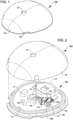
- FIGS. 1 and 2 respectively illustrate a perspective view of a monitoring device 100 and a partially, exploded view of the monitoring device 100 including a biosensor 102, according to various examples.
- the monitoring device 100 may be a wearable monitoring device that is mounted to a body at an exterior surface (e.g., against a person's skin), held against the body at the exterior surface, implanted within the body (e.g., subcutaneously beneath the person's skin), or mounted in any other suitable manner.
- the monitoring device 100 includes a top enclosure 104, bottom enclosure 106, a moisture barrier seal area 108, and the biosensor 102.
- the top enclosure 104 and the bottom enclosure 106 together form a housing that encloses the biosensor 102 therein.
- a lower portion of the housing e.g., the bottom enclosure 106
- An upper portion of the housing e.g., the top enclosure 104
- a smooth surface, free from sharp edges, may be desirable to decrease the potential for knocking the monitoring device 100 from the person's skin once mounted.
- the monitoring device 100 may be worn under clothing (e.g., on the person's arm), and the smooth surface decreases the potential of the person's clothing snagging on the monitoring device 100.
- the biosensor 102 e.g., an analyte sensor, glucose sensor, or other electromechanical sensor for use in sensing biological information of a person, includes a sensor cable support device 110, a sensor cable 112, sensing circuitry 114, a power source 116 such as a battery, a printed circuit board (“PCB") 118, and an antenna 120.
- the sensor cable 112 includes a proximal end portion 112a and a distal end portion 112b (see FIG. 6 ).
- the proximal end portion 112a is supported by the sensor cable support device 110.
- the proximal end portion 112a may be disposed within a groove or channel of the sensor cable support device 110 and physically retained by pucks 122a, 122b.
- the proximal end portion 112a is also electrically connected to the PCB 118 via the sensor cable support device 110.
- the sensor cable support device 110 may include a set of electrical traces that extend proximate to a middle area of the sensor cable support device 110 toward the PCB 118.
- the cable alignment structure may 126 may also be integrated into the sensor cable support device 110.
- an elongated cylindrical leg may be formed in the sensor cable support device 110 through which the sensor cable 112 may extend as it through the PCB 118.
- the distal end portion 112b which includes one or more electrodes, is injected into a person's skin to measure biological parameters (e.g., glucose levels) in the interstitial fluid of subcutaneous tissue beneath the skin.
- the sensor cable 112 may include a curved portion that extends through a bottom opening 124 in the PCB 118 and the bottom enclosure 106.
- a cable alignment structure 126 is included on the PCB 118 at a position adjacent to the bottom opening 124.
- the cable alignment structure 126 may include a pair of tabs, a groove, or other structure capable of aligning the sensor cable 112 through the bottom opening 124.
- the cable alignment structure 126 can be a component that is attached to the PCB 118 or may be integrated into the construction of the bottom enclosure 106 (e.g., formed at the same time and using the same approach as was used to form the bottom enclosure 106).
- the top enclosure 104 includes a top opening 127 that is disposed above the bottom opening 124.
- the top opening 127 may be inserted an insertion needle to inject the distal portion 112b of the sensor cable 112 underneath the person's skin.
- the top opening 127 is formed from a deformable material that can reseal after the insertion needle has been inserted therethrough. In this manner, the sensor cable 112 can be injected without interrupting the moisture seal of the top enclosure 104.
- the placing the insertion needle in the bottom opening 124, with the monitoring device 100 pressed against the person's skin, may achieve the proper alignment for the insertion needle to insert the sensor cable 112 into the person's skin.
- the bottom opening 124 includes a sensor guiding structure that may be used to guide the insertion needle through the monitoring device 100.
- the sensor cable support device 110 may be suitably rigid to support the sensor cable 112 and, in some example, provide structural support to the PCB 118.
- the sensor cable support device 110 may be formed from liquid crystal polymer.
- the PCB 118 may be a flexible printed circuit board ("FPCB"). In this example, attaching the sensor cable support device 110 to the PCB 118 may add rigidity to the entire monitoring device 100, in addition to the flexible PCB 118.
- the sensor cable support device 110 may be considered an interconnect device.
- the sensor cable support device 110 stands off from the PCB 118 and may stand above components (e.g., the sensing circuitry 114, the power source 116, etc.) disposed below it, the sensor cable support device 110 functions to save space within the monitoring device 100. This may result in the monitoring device 100 having a smaller footprint.
- the PCB 118 may be placed close to the person's skin unlike other monitoring devices that include a standoff fixture. This provides for improved wearer comfort and less overall device bulk.
- the sensing circuitry 114 includes a processing device and a computer-readable medium, such as a random access memory (“RAM”) coupled to the processing device.
- the processing device may execute computer-executable program instructions stored in memory, such as executing one or more computer programs.
- processing devices may comprise a microprocessor, a digital signal processor ("DSP"), an application-specific integrated circuit (“ASIC”), field programmable gate arrays (“FPGAs”), state machines, or other processing means for processing electrical signals received from electrodes the sensor cable 112 (e.g., see FIG. 5 ).
- Such processing means may further include programmable electronic devices such as PLCs, programmable interrupt controllers ("PICs”), programmable logic devices (“PLDs”), programmable read-only memories (“PROMs”), electronically programmable read-only memories (“EPROMs” or “EEPROMs”), or other similar devices.
- PLCs programmable electronic devices
- PLCs programmable interrupt controllers
- PLDs programmable logic devices
- PROMs programmable read-only memories
- EPROMs electronically programmable read-only memories
- EEPROMs electronically programmable read-only memories
- the processing device may include, or may be in communication with, media, for example computer-readable storage media, that may store instructions that, when executed by the processing device, cause the processing device to perform the steps described herein as carried out, or assisted, by a processing device.
- Examples of computer-readable media may include, but are not limited to a memory chip, ROM, RAM, ASIC, or any other storage means from which a processing device can read or write information.
- the antenna 120 may enable transmission of information from the monitoring device 100 (e.g., to one or more electronic devices).
- a transceiver included in the sensing circuitry 114 or otherwise, may use the antenna 120 to transmit real-time glucose readings monitored by the biosensor 102.
- the transceiver may also use the antenna 120 to receive information from one or more other electronic devices (e.g., instructions to adjust settings of the biosensor 102, updates to software or firmware of the biosensor 102, etc.).
- the top enclosure 104 and the bottom enclosure 106 may together form a housing for retaining the biosensor 102, with the moisture barrier 108 being disposed between the top enclosure 104 and the bottom enclosure 106.
- the housing may be compact in size for placing on a person's skin.
- the housing may be made of any suitable material for housing the biosensor 102. Non-limiting examples of materials that may be suitable for the housing include silicone, polyethylene, polyvinyl chloride (“PVC”), polypropylene, nylon, polyurethane, polycarbonate, steel, aluminum, and other plastics and metals.
- the top enclosure 104 When assembled, the top enclosure 104 encloses the biosensor 102 and mates with the bottom enclosure 106 (e.g., by way of a snap-fit, welded joint, or other). The top enclosure 104 may also be glued or otherwise bonded to the bottom enclosure 106.
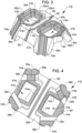
- FIGS. 3 and 4 respectively illustrate a top, perspective view of the sensor cable support device 110 and a bottom, perspective view of the sensor cable support device 110, according to various examples.
- the sensor cable support device 110 which is a type of molded interconnect device, may include a body 302 and a set of legs 304.
- the body 302 includes a top side or top surface 302a and a bottom side or bottom surface 302b. When installed, the top side 302a faces the top enclosure 104 and the bottom side 302b faces the PCB 118.
- the sensor cable support device 110 may have a height of about 2 mm, a width of about 4 mm, and a length of about 4 mm. In other examples, the height, width, and/or length of the sensor cable support device 110 may be respectively greater than or less than 2 mm, 4 mm, and/or 4 mm. The height of about 2 mm may be selected to be less than the height of the power source 116. The height of about 2 mm may also provide a suitable separation between the proximal end portion 112a of the sensor cable 112 and the sensing circuitry 114 and other electronic components attached to or otherwise disposed on or within the PCB 118.
- the set of legs 304 extend from one side of the body 302, extend below the body 302, and, in some examples, include a corresponding set of feet 308.
- the body 302 may be oriented in a first plane and the set of feet 308 may be oriented in a second, different plane.
- the set of legs 304 may extend between the first plane and the second plane to connect the body 302 to the set of feet 308.
- the body 302 may be oriented in the first plane when a substantial portion of the body 302 is located in the first plane.
- the set of feet 308 (e.g., distal ends of the set of legs 304) may be oriented in the second plan when substantial portions of the set of feet 308 is located in the second plane.
- the set of feet 308 may include conductive pads 310.
- the sensor cable support device 110 may be electrically and structurally attached to the PCB 118 or other structure using the conductive pads 310.
- the feet 308 are connected to the PCB 118 using surface mount technology.
- the conductive openings 312 may extend through the body 302 from the top side 302a to the bottom side 302b.
- the conductive openings 312 are defined as cavities which do not extend through the body 302.
- the conductive openings 312 may be sized and configured to receive the pucks 122.
- the conductive openings 312 may have a rectangular cross section, but it is understood that any other cross sectional shape may be used (e.g., square, circular, oval, etc.).
- the conductive openings 312 may include geometric features that correspond to those of the pucks 122 such that the pucks 122, when installed, retain the sensor cable 112 in contact with the body 302.
- the conductive surfaces 314a, 314b are disposed within the conductive openings 312.
- the conductive surface 314a which may include a conductive material that has been applied or otherwise deposited on the inward and outward facing surfaces of the conductive opening 312a, may be electrically coupled to an electrical trace 316a.
- the electrical trace 316a extends from the conductive surface 314a, along the leg 304a, and connects with the conductive pad 310a.
- the conductive surface 314b which may include a conductive material that has been applied or otherwise deposited on the inward and outward facing surfaces of the conductive opening 312b, may be electrically coupled to an electrical trace 316b.
- the electrical trace 316b extends from the conductive surface 314b, along the leg 304b, and connects with the conductive pad 310b. In this manner, the conductive surface 314a and the electrical trace 316a are electrically isolated from the conductive surface 314b and the electrical trace 316b.
- the electrical traces 316 may extend along an outside surface of the sensor cable support device 110 and/or may be disposed within the sensor cable support device 110.
- an electrical guard structure 318 may be formed within the body 302.
- the purpose of the electrical guard structure 318 is to minimize current leakage between the conductive openings 312a, 312b.
- the electrical guard structure 318 can be any suitable cavity, channel, hole, opening, or structure that is disposed between two electrically isolated contacts. In some examples, electrical guard structure 318 functions like a guard trace to minimize crosstalk between two traces.
- the electrical guard structure 318 includes a channel or hole in the top side 302a, an opening that extends from the top side 302a to the bottom side 302b, and/or a guard trace 320.
- the guard trace 320 as illustrated in FIGS. 3-6 , may extend from the top side 302a to the bottom side 302b, along a back side (as shown in FIGS. 5 and 6 ), and along one or more legs 304 (e.g., 304c, 304d).
- the guard trace 320 may terminate at one or more conductive pads 310 (e.g., 310c, 310d), by which the guard trace 320 may be electrically coupled to the PCB 118.
- a groove 322 can be formed in the top side 302a of the body 302 of the sensor cable support device 110.
- the groove 322 can span the two conductive openings 312.
- the groove 322 is defined to include groove parts 322a-1, 322a-2, 322b-1, and 322b-2.
- the groove parts 322a correspond to the conductive opening 312a and extend through at least a portion of the conductive surface 314a and a portion of the top side 302a adjacent to the conductive opening 312a.
- the groove parts 322b correspond to the conductive opening 312b and extend through at least a portion of the conductive surface 314b and a portion of the top side 302a adjacent to the conductive opening 312b.
- the groove 322 is sized to correspond to the sensor cable 112.
- the groove parts 322a are sized to correspond to a first portion of the sensor cable 112 (e.g., a first electrode having a first cross sectional area) and the groove parts 322b are sized to correspond to a second portion of the sensor cable 112 (e.g., a second electrode having a second cross sectional area).
- the groove 322 has a consistent shape and size.
- the groove parts 322a and 322b can be aligned in a coaxial manner such that an elongate straight sensor cable 112 can contact all groove parts 322a and 322b.
- the groove 322 may enable one or more independent electrical contact points between the sensor cable 112 and the conductive surface 314 (e.g., at the groove parts 322a-1, 322a-2, 322b-1, and 322b-2). Additionally, when the pucks 122 are also conductive, the number of contacts points increases even more. For example, the pucks 122 may physically contact one or more interior faces of the conductive openings 312 where the conductive surface 314 is disposed, forming more surfaces for electrical contact.
- the sensor cable support device 110 may also include an orientation structure 324.
- the orientation structure 324 may be used to orient and/or align the sensor cable support device 110 during assembly and/or to align the top enclosure 104 with the bottom enclosure 106.
- the sensor cable support device 110 may be formed in any suitable manner including, for example, injection molding, or other suitable techniques.
- the sensor cable support device 110 may be formed as a single piece including at least the body 302, the legs 304, and/or the feet 308.
- the sensor cable support device 110 may be formed from any suitable material including, for example, liquid crystal polymer (e.g., RTP 3499-3 X 113393 A sold by RTP Co., VECTRA ® E840i LDS sold by Ticon, etc.), high-temperature nylon, polyetheretherketone (“PEEK”), and other similar materials.
- the material selected for the sensor cable support device 110 may be non-conductive, have low moisture absorption properties, have low water vapor transmission rates, and may be easily moldable into very thin walls.
- the material selected for the sensor cable support device 110 may be capable of LDS processing.
- the rigidity of the sensor cable support device 110 may depend on one or both of the sensor cable support device's 110 thickness and the material forming the sensor cable support device 110.
- the sensor cable support device's 110 thickness may be inversely proportional to the density of the material (e.g., a denser material may allow for a thinner sensor cable support device 110 while a less dense material may require a thicker sensor cable support device 110).
- the electrical traces 316, 320 and the conductive surfaces 314 may be formed in the sensor cable support device 110 using any suitable technique.
- suitable techniques include LDS processing and corresponding techniques for depositing a conductive material such as copper, nickel, gold, etc. in a circuit pattern.
- Such techniques may include electroless copper plating.
- Such techniques may include those using Enplate ® LDS AG-600 as sold by Enthone ® .
- the electrical traces 316, 320 and the conductive surfaces 314 may have a thickness of about 1 micron. In some examples, the electrical traces 316, 320 and the conductive surfaces 314 have a thickness of less than 1 micron (e.g., 0.25 microns to 0.5 microns). In some examples, the electrical traces 316, 320 and the conductive surfaces 314 may be formed using other plating techniques.
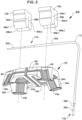
- FIGS. 5 and 6 respectively illustrate a top, exploded perspective view of a sensor holder system 500 and a bottom, perspective view of the sensor holder system 500, according to various examples.
- the sensor holder system 500 in this example, is defined to include the sensor cable support device 110, the sensor cable 112, and the pucks 122.
- the sensor cable 112 may include one or more electrodes, chemicals, or other means for generating biological information.
- the sensor cable 112 may be a coaxial sensor and include two electrodes 502a, 502b that are inserted into the person's skin to expose the electrodes 502a, 502b to the interstitial fluid in the person's subcutaneous tissue.
- the sensor cable 112 may include two or more separate wires that are not included in the same coating.
- the electrode 502b includes at least a portion of the sensor cable 112 made of platinum or having a platinum coating and electrode 502a includes a silver/silver-chloride ("Ag/AgCl”) material that covers a part of electrode 502b.
- the electrodes 502b, 502a may be used to generate glucose information about the person by generating electrical signals corresponding to an amount of glucose present within the interstitial fluid.
- a reactive material such as glucose oxidase ("GOX")
- GOX glucose oxidase
- a voltage is applied to the electrodes 502b, 502a, an electrical current is generated based on the amount of these reaction products generated by the glucose/GOX reaction.
- the electrical current is routed through the sensor cable 112 to the sensing circuitry 114.
- the sensing circuitry 114 may use the strength of the current to determine glucose information such as the person's glucose levels.
- the biosensor 102 may be configured to measure other biological parameters without departing from the scope of the present disclosure.
- the chemical materials applied onto the sensor cable 112 to form the electrodes 502b, 502a and the reactive material coated onto the electrodes 502b, 502a may be suitable for a glucose sensor, other material may be used according to other examples, based on the application of the biosensor 102.
- the sensor cable's 112 length may allow the sensor cable 112 to extend from beneath the person's skin to the sensor cable support device 110 with allowance for the person's movement.
- the sensor cable 112 may be between approximately 10 millimeters to 30 millimeters long.
- the sensor cable's 112 thickness, or gauge may be selected to allow the sensor cable 112 to remain injected into the skin during this period with minimal discomfort.
- the sensor cable 112 includes an outer diameter of approximately 100-200 microns for portions of the cable coated with the electrode 502a and an outer diameter of approximately 100 microns for the electrode 502b.
- the sensor cable 112 generally may have a maximum outer diameter approximately between 100 microns and 300 microns. In some examples, however, the sensor cable 112 may have an outer diameter of about 50 microns.
- a first dimensional measurement (e.g., a width, a depth, a cross-sectional area, etc.) taken laterally across the groove 322 taken at the groove parts 322a may be different from a second dimensional measurement taken laterally across the groove 322 taken at the groove parts 322b. These differences may be included in the groove 322 to accommodate the electrodes 502a, 502b. As described herein, the electrodes 502a, 502b may be of different sizes (e.g., have different diameters). The different lateral measurements may be selected based on the respective widths of the proximate end 112a of the sensor cable at different locations. For example, one portion of the proximate end of the sensor cable 112 may be an exposed platinum electrode 502b, which may have a narrower gauge than another portion which includes the platinum wire coated with a silver/silver-chloride electrode 502a.
- FIG. 5 illustrates the sensor holder system 500 in a disassembled state, e.g., the pucks 122 and the sensor cable 112 are illustrated as being removed from the conductive openings 312.
- FIG. 6 illustrates the sensor holder system 500 in a coupled state, e.g., the sensor cable 112 is illustrated as being held within the groove 322 and the pucks 122 are illustrated as being installed in the conductive openings 312.
- the pucks 122 when installed, retain the sensor cable 112 in physical contact with the sensor cable support device 110 and electrically couple the electrodes 502 of the sensor cable 112 with the conductive surface(s) 314 in the conductive openings 312.
- the pucks 122 may be formed from an electrically conductive elastomer material (e.g., silicon elastomer with carbon added or other similar material).
- the pucks 122 may be molded, extruded, stamped, or otherwise formed using any suitable technique.
- Each puck 122 may include a pair of legs 504-1, 504-2 separated by a slit 508.
- the slit 508 may be sized sufficiently large to receive the proximate end portion 112a of the sensor cable 112. In some examples, the slit 508 is less than 1 mm in width. The slit 508 may also be larger or smaller than 1 mm.
- the slit 508 may also include a portion that corresponds in shape to an outer diameter of the sensor cable 112. For example, the slit 508 may include a cylindrical cutout at the top of the slit 508 corresponding to the sensor cable 112. In some examples, the slits 508 may be sized to accommodate the different diameters of the sensor cable 112.
- the pucks 122 may be sized and configured to be installed within the conductive openings 312.
- the pucks 122 are formed from a deformable conductive material that can be pressed or otherwise forced into the conductive openings 312. Once within the conductive openings, the deformable material of the pucks 122 (e.g., the pair of legs 504) expands and uses friction to hold the pucks 122 in place.
- the legs 504 may include retaining structures 506-1, 506-2. As illustrated in FIG. 6 , the retaining structures 506 may spring outwards once the pucks 122 have been installed into the conductive openings 312 such that the retaining structures 506 engage with the bottom side 302b. In this manner, the pucks 122 may be "snapped" into the conductive openings 312.
- the pucks 122 may be installed manually and/or in an automated fashion.
- the 122 pucks may be installed from the top side 302a or from the bottom side 302b.
- the sensor cable 112 and the grooves 322 may be disposed on the bottom side 302b.
- the pucks 122 may be installed into the conductive openings 312 before the sensor cable support device 110 is connected to the PCB 118.
- the sensor cable 112 may be connected to the sensor cable support device 110 before or after the sensor cable support device 102 has been connected to the PCB 118.
- top sides of the pucks 122 may include a substantially planar area (e.g., greater than 1 mm ⁇ 2). This topside area may be suitable sized and suitably flat to allow a suction head of a robotic placement device (e.g., a pick and place device) to grasp the pucks 122 and place the pucks into the conductive openings 312 and thereby physically support and electrically couple the sensor cable 112 to the electrical traces 306.
- a robotic placement device e.g., a pick and place device
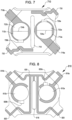
- FIG. 7 illustrates a top view of a sensor cable support device 710, according to at least one example.
- the sensor cable support device 710 includes a pair of conductive openings 712a, 712b. Within the conductive openings 712a, 712b are a pair of pucks 722a, 722b. In the example illustrated by FIG. 7 , the pucks 722 have been installed from the bottom side of the sensor cable support device 710. Thus, slits 724a, 724b are visible in the view presented in FIG. 7 .
- the sensor cable support device 710 also includes alignment grooves 726a, 726b. The alignment grooves 726 may be used to align the pucks 722 during installation into the conductive openings 712.
- the alignment grooves 726 help retain the pucks 722 after installation.
- the sensor cable support device 710 also includes electrical traces 716a, 716b, which are respectively connected to the conductive openings 712a, 712b.
- the sensor cable support device 710 also includes an electrical guard structure 718 disposed between the conductive openings 712 and guard traces 720a, 720b.
- the electrical guard structure 718 may be a recessed channel and/or may be a through hole. In any event the electrical guard structure 718 may function to minimize leakage between the conductive conductive openings 712.
- the guard traces 720a, 720b may perform a similar function as the electrical guard structure 718.
- FIGS. 8 and 9 respectively illustrate a top view and a top, perspective view of a sensor cable support device 810, according various examples.
- the sensor cable support device 810 includes a pair of conductive openings 812a, 812b.
- the conductive openings 812 which include a portion thereof coated in conductive material, are electrically coupled to electrical traces 816a, 816b. As illustrated, in some examples, only a portion of the conductive openings 812 includes conductive material.
- the sensor cable support device 810 also includes alignment grooves 826a, 826b.
- the alignment grooves 826 may be used to align pucks during installation into the conductive openings 812. In some examples, the alignment grooves 826 help retain the pucks after installation.
- the sensor cable support device 810 also includes an electrical guard structure 818 and a guard trace 820.
- the guard trace 820 may include a more intricate pattern that includes at least two individual traces that extend between the conductive openings 812.
- the guard trace 820 also extends into the electrical guard structure 818 and down all four legs of the sensor cable support device 110 and/or down two legs.
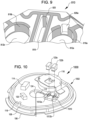
- FIG. 10 illustrates a partially exploded view of a monitoring device 1000 including an integrated sensor cable support device 1010, which is part of biosensor 1002, according to at least one example.
- the monitoring device 1000 is an example of the monitoring device 100 described herein.
- the monitoring device 1000 includes bottom enclosure 106, the moisture barrier 108, the PCB 118, the antenna 120, the sensing circuitry 114, and the power source 116.
- the sensor cable support device of the monitoring device 1000 has been integrated into the PCB 118.
- the sensor cable support device 1010 has been printed in the same manner (e.g., using the same manufacturing techniques) as the PCB 118.
- the integrated sensor cable support device 1010 is integrated in the sense that it is integrated into the PCB 118.
- the integrated sensor cable support device 1010 includes a pair of conductive openings 1012a, 1012b sized and configured to receive the pucks 122a, 122b.
- the pair of conductive openings 1012a, 1012b may not extend through the PCB 118.
- the conductive openings 1012 may be cavities into which the pucks 122 may be installed.
- the pucks 122 may function to electrically and mechanically connect the sensor cable 112 to the sensor cable support device 1010.
- references herein to an example or implementation means that a particular feature, structure, operation, or other characteristic described in connection with the example may be included in at least one implementation of the disclosure.
- the disclosure is not restricted to the particular examples or implementations described as such.
- the appearance of the phrases "in one example,” “in an example,” “in one implementation,” or “in an implementation,” or variations of the same in various places in the specification does not necessarily refer to the same example or implementation.
- Any particular feature, structure, operation, or other characteristic described in this specification in relation to one example or implementation may be combined with other features, structures, operations, or other characteristics described in respect of any other example or implementation.
- a or B or C includes any or all of the following alternative combinations as appropriate for a particular usage: A alone; B alone; C alone; A and B only; A and C only; B and C only; and all three of A and B and C.
Landscapes
- Health & Medical Sciences (AREA)
- Life Sciences & Earth Sciences (AREA)
- Physics & Mathematics (AREA)
- Engineering & Computer Science (AREA)
- Molecular Biology (AREA)
- General Health & Medical Sciences (AREA)
- Biophysics (AREA)
- Biomedical Technology (AREA)
- Heart & Thoracic Surgery (AREA)
- Medical Informatics (AREA)
- Veterinary Medicine (AREA)
- Surgery (AREA)
- Animal Behavior & Ethology (AREA)
- Pathology (AREA)
- Public Health (AREA)
- Optics & Photonics (AREA)
- Microelectronics & Electronic Packaging (AREA)
- Emergency Medicine (AREA)
- Chemical & Material Sciences (AREA)
- Chemical Kinetics & Catalysis (AREA)
- General Chemical & Material Sciences (AREA)
- Measurement Of The Respiration, Hearing Ability, Form, And Blood Characteristics Of Living Organisms (AREA)
- Measuring And Recording Apparatus For Diagnosis (AREA)
Claims (18)
- Stützvorrichtung (110) zum Stützen eines Sensorkabels (112), wobei die Stützvorrichtung (110) Folgendes umfasst:einen starren Körper (302), der ein Öffnungspaar (312) definiert, wobei jede Öffnung (312) so dimensioniert und konfiguriert ist, dass sie eine leitfähige Scheibe (122) aufnimmt, wobei der starre Körper (302) so konfiguriert ist, dass er ein proximales Ende des Sensorkabels (112) stützt und das Sensorkabel (112) mit Sensorschaltung (114) einer Überwachungsvorrichtung (100) elektrisch koppelt; gekennzeichnet durcheinen Satz starrer Beine (304), die mit dem starren Körper (302) verbunden sind und sich von der Unterseite (302b) des starren Körpers (302) weg erstrecken;eine erste elektrische Bahn (316a), die eine erste Öffnung (312a) des Öffnungspaars (312) und ein distales Ende eines ersten Beins (304a) des Satzes starrer Beine (304) elektrisch koppelt; undeine zweite elektrische Bahn (316b), die eine zweite Öffnung (312b) des Öffnungspaars (312) und ein distales Ende eines zweiten Beins (304b) des Satzes starrer Beine (304) elektrisch koppelt.
- Stützvorrichtung (110) nach Anspruch 1, wobei eine Rille (322) auf der Unterseite (302b) des starren Körpers (302) oder auf einer Oberseite (302a) des starren Körpers (302), die gegenüber der Unterseite (302b) ist, gebildet wird, wobei die Rille (322) so dimensioniert und konfiguriert ist, dass sie das Sensorkabel (112) unterbringt.
- Stützvorrichtung (110) nach Anspruch 2, wobei die Rille (322) Folgendes definiert:eine erste Region (322a), die angrenzend zu der ersten Öffnung (312a) angeordnet ist, wobei die erste Region (322a) eine erste Querschnittsfläche aufweist und so dimensioniert ist, dass sie einen ersten Abschnitt des Sensorkabels (112), einschließend einen ersten Draht unterbringt; undeine zweite Region (322b), die angrenzend zu der zweiten Öffnung (312b) angeordnet ist, wobei die zweite Region (322b) eine zweite Querschnittsfläche aufweist und so dimensioniert ist, dass sie einen zweiten Abschnitt des Sensorkabels (112), einschließend einen zweiten Draht unterbringt, wobei die erste Querschnittsfläche von der zweiten Querschnittsfläche unterschiedlich ist.
- Stützvorrichtung (110) nach einem der Ansprüche 1-3, weiter umfassend eine elektrische Schutzstruktur (318), die zwischen dem Öffnungspaar (312) angeordnet ist.
- Stützvorrichtung (110) nach Anspruch 4, wobei die elektrische Schutzstruktur (318) eine dritte elektrische Bahn (320) umfasst, die sich zu einem distalen Ende eines dritten Beins (304c, 304d) des Satzes starrer Beine (304) erstreckt,
oder wobei die elektrische Schutzstruktur (318) eine Schutzöffnung umfasst, die in dem starren Körper (302) gebildet ist und sich durch den starren Körper (302) erstreckt. - Stützvorrichtung (110) nach einem der Ansprüche 1-5, wobei der Satz starrer Beine (304) einstückig in den starren Körper (302) integriert ist.
- Stützvorrichtung (110) nach einem der Ansprüche 1-6, wobei sich das Öffnungspaar (312) durch den starren Körper (302) erstreckt.
- Stützvorrichtung (110) nach einem der Ansprüche 1-7, wobei der starre Körper (302) innerhalb des Öffnungspaars (312) leitfähige Plattierung umfasst.
- Stützvorrichtung (110) nach einem der Ansprüche 1-8, wobei die erste Öffnung (312a) von der zweiten Öffnung (312b) elektrisch isoliert ist.
- Stützvorrichtung (110) nach einem von Anspruch 1-9, wobei:der starre Körper (302) und der Satz starrer Beine (304) Merkmale dafür aufweisen, aus einem ersten Material unter Verwendung einer Spritzgießtechnik hergestellt worden zu sein; unddie erste und zweite elektrische Bahn (316a, b) Merkmale dafür aufweisen, unter Verwendung einer Laser-Direktstrukturierungstechnik gebildet worden zu sein, wobei die erste und zweite elektrische Bahn (316a, b) ein zweites Material umfassen.
- Sensorkabelstützsystem, umfassend:eine Stützvorrichtung (110) nach einem der Ansprüche 1-10,wobei das Öffnungspaar ein Paar leitfähiger Öffnungen (312) ist; undein Sensorkabel (112), umfassend:einen ersten Abschnitt in elektrischem Kontakt mit einer ersten leitfähigen Öffnung (312a) des Paars leitfähiger Öffnungen (312), um eine erste elektrische Verbindung zu bilden; undeinen zweiten Abschnitt in elektrischem Kontakt mit einer zweiten leitfähigen Öffnung (312b) des Paars leitfähiger Öffnungen (312), um eine zweite elektrische Verbindung zu bilden; undein Scheibenpaar (122), das in dem Paar leitfähiger Öffnungen (312) so installiert ist, dass eine erste Scheibe (122a) des Scheibenpaars (122) den ersten Abschnitt mechanisch in elektrischem Kontakt mit der ersten leitfähigen Öffnung (312a) hält, und eine zweite Scheibe (122b) des Scheibenpaars (122) den zweiten Abschnitt mechanisch in elektrischem Kontakt mit der zweiten leitfähigen Öffnung (312b) hält.
- Sensorkabelstützsystem nach Anspruch 11, wobei der erste Abschnitt des Sensorkabels (112) durch eine erste Querschnittsfläche definiert ist und der zweite Abschnitt des Sensorkabels (112) durch eine zweite Querschnittsfläche definiert ist, die größer ist als die erste Querschnittsfläche.
- Sensorkabelstützsystem nach einem der Ansprüche 11 und 12, wobei die Stützvorrichtung (110) in eine Leiterplatte (118) so integriert ist, dass die Stützvorrichtung (110) und die Leiterplatte (118) unter Verwendung von Leiterplattenherstellungstechnik gebildet werden.
- Tragbare Überwachungsvorrichtung (100), umfassend:eine Leiterplatte (118), die in einem Gehäuse (104, 106) angeordnet ist, das eine Außenoberfläche zum Positionieren der tragbaren Überwachungsvorrichtung (100) auf der Haut einer Person aufweist;Sensorschaltung (114), umfassend eine oder mehrere elektronische Komponenten, die mit der Leiterplatte (118) verbunden sind; undein Sensorhaltersystem, das ein Sensorkabelstützsystem nach einem der Ansprüche 11-13 ist, wobei das Sensorhaltersystem über den Satz von Beinen (304) der Stützvorrichtung (110) des Sensorhaltersystems physisch mit der Leiterplatte (118) gekoppelt ist, und das Paar leitfähiger Öffnungen (312), das in dem Körper (302) der Stützvorrichtung (110) des Sensorhaltersystems definiert ist, elektrisch mit der Leiterplatte (118) gekoppelt ist;wobei das Sensorkabel (112) elektrisch mit der Sensorschaltung (114) gekoppelt ist.
- Tragbare Überwachungsvorrichtung (100) nach Anspruch 14, wobei das Scheibenpaar (122) aus einem leitfähigen Material gebildet ist.
- Tragbare Überwachungsvorrichtung (100) nach einem der Ansprüche 14 und 15, wobei:jede Scheibe (122) des Scheibenpaars (122) einen Schlitz (508) definiert;der erste Abschnitt des Sensorkabels (112) innerhalb eines ersten Schlitzes (508) der ersten Scheibe (122) gehalten wird, wenn die erste Scheibe (122) in der ersten leitfähigen Öffnung (312a) installiert ist; undder zweite Abschnitt des Sensorkabels (112) innerhalb eines zweiten Schlitzes (508) der zweiten Scheibe (122) gehalten wird, wenn die zweite Scheibe (122) in der zweiten leitfähigen Öffnung (312b) installiert ist.
- Tragbare Überwachungsvorrichtung (100) nach einem der Ansprüche 14-16, wobei sich der erste Abschnitt des Sensorkabels (112) über die erste leitfähige Öffnung (312a) erstreckt und an zwei oder mehreren Stellen in physischem Kontakt mit der ersten leitfähigen Öffnung (312a) steht.
- Tragbare Überwachungsvorrichtung (100) nach einem der Ansprüche 14-17, wobei das Sensorkabel (112) eine erste Elektrode (502a), die dem ersten Abschnitt entspricht, und eine zweite Elektrode (502b), die dem zweiten Abschnitt entspricht, umfasst.
Priority Applications (1)
| Application Number | Priority Date | Filing Date | Title |
|---|---|---|---|
| EP24196136.6A EP4480395A3 (de) | 2018-03-28 | 2019-03-28 | Sensorkabelhaltevorrichtung mit mechanischen verbindern |
Applications Claiming Priority (2)
| Application Number | Priority Date | Filing Date | Title |
|---|---|---|---|
| US201862649350P | 2018-03-28 | 2018-03-28 | |
| PCT/US2019/024605 WO2019191446A1 (en) | 2018-03-28 | 2019-03-28 | Sensor cable support device including mechanical connectors |
Related Child Applications (1)
| Application Number | Title | Priority Date | Filing Date |
|---|---|---|---|
| EP24196136.6A Division EP4480395A3 (de) | 2018-03-28 | 2019-03-28 | Sensorkabelhaltevorrichtung mit mechanischen verbindern |
Publications (2)
| Publication Number | Publication Date |
|---|---|
| EP3773201A1 EP3773201A1 (de) | 2021-02-17 |
| EP3773201B1 true EP3773201B1 (de) | 2024-09-11 |
Family
ID=66290539
Family Applications (2)
| Application Number | Title | Priority Date | Filing Date |
|---|---|---|---|
| EP19720000.9A Active EP3773201B1 (de) | 2018-03-28 | 2019-03-28 | Sensorkabelstützvorrichtung mit mechanischen verbindern |
| EP24196136.6A Pending EP4480395A3 (de) | 2018-03-28 | 2019-03-28 | Sensorkabelhaltevorrichtung mit mechanischen verbindern |
Family Applications After (1)
| Application Number | Title | Priority Date | Filing Date |
|---|---|---|---|
| EP24196136.6A Pending EP4480395A3 (de) | 2018-03-28 | 2019-03-28 | Sensorkabelhaltevorrichtung mit mechanischen verbindern |
Country Status (8)
| Country | Link |
|---|---|
| US (7) | US10588551B2 (de) |
| EP (2) | EP3773201B1 (de) |
| JP (3) | JP7395493B2 (de) |
| CN (1) | CN112074231A (de) |
| AU (2) | AU2019243181B2 (de) |
| CA (1) | CA3093986A1 (de) |
| DK (1) | DK3773201T3 (de) |
| WO (1) | WO2019191446A1 (de) |
Families Citing this family (15)
| Publication number | Priority date | Publication date | Assignee | Title |
|---|---|---|---|---|
| USD794801S1 (en) * | 2015-07-09 | 2017-08-15 | Dexcom, Inc. | Base for medical device electronic module |
| USD794201S1 (en) * | 2015-07-09 | 2017-08-08 | Dexcom, Inc. | Medical device electronic module |
| USD794800S1 (en) | 2015-07-09 | 2017-08-15 | Dexcom, Inc. | Medical device inserter |
| US11395631B2 (en) | 2017-06-23 | 2022-07-26 | Dexcom, Inc. | Transcutaneous analyte sensors, applicators therefor, and associated methods |
| EP3700416B1 (de) | 2017-10-24 | 2024-06-26 | Dexcom, Inc. | Vorverbundene analytsensoren |
| GB2569816B (en) * | 2017-12-29 | 2019-12-25 | Wearable Tech Limited | Supporting an Electrical Connector for a Peripheral Device on an Item of Clothing |
| EP3773201B1 (de) * | 2018-03-28 | 2024-09-11 | Dexcom, Inc. | Sensorkabelstützvorrichtung mit mechanischen verbindern |
| US11510596B2 (en) | 2019-04-22 | 2022-11-29 | Dexcom, Inc. | Preconnected analyte sensors |
| US20200330007A1 (en) * | 2019-04-22 | 2020-10-22 | Medtronic Minimed, Inc. | Sensor with substrate including integrated electrical and chemical components and methods for fabricating the same |
| TWI733304B (zh) * | 2019-08-02 | 2021-07-11 | 華廣生技股份有限公司 | 一種用於承載感測器之容器及其容器操作方法 |
| JP2023534645A (ja) | 2020-07-08 | 2023-08-10 | アボット ダイアベティス ケア インコーポレイテッド | 干渉信号を低減するための強化を特徴とする検体センサ |
| USD974201S1 (en) * | 2020-08-27 | 2023-01-03 | Medtrum Technologies Inc. | Installer for analyte detector |
| EP4503883A3 (de) | 2020-09-07 | 2025-07-30 | Ascensia Diabetes Care Holdings AG | Verfahren und vorrichtung zur kopplung einer elektronikeinheit an eine basiseinheit einer kontinuierlichen analytüberwachungsvorrichtung |
| EP4267002A4 (de) * | 2020-12-23 | 2025-02-26 | Abbott Diabetes Care Inc. | Analytsensoren mit reduziertem störsignal und verfahren |
| DE102021131789A1 (de) * | 2021-12-02 | 2023-06-07 | Webasto SE | Fahrzeugdach mit Halteeinrichtung für mindestens zwei Umfeldsensoren |
Family Cites Families (22)
| Publication number | Priority date | Publication date | Assignee | Title |
|---|---|---|---|---|
| US1534265A (en) * | 1924-02-09 | 1925-04-21 | Harrison William Henry | Garment hanger |
| US5626479A (en) * | 1993-07-16 | 1997-05-06 | Hughes; Michael T. | Unified connector interface adapter |
| US6965791B1 (en) * | 2003-03-26 | 2005-11-15 | Sorenson Medical, Inc. | Implantable biosensor system, apparatus and method |
| US8160669B2 (en) * | 2003-08-01 | 2012-04-17 | Dexcom, Inc. | Transcutaneous analyte sensor |
| US8886272B2 (en) * | 2004-07-13 | 2014-11-11 | Dexcom, Inc. | Analyte sensor |
| CA2474547C (en) | 2004-07-16 | 2012-01-03 | Xantrex International | Electrical connector apparatus and cover therefor |
| US8272876B2 (en) * | 2010-07-20 | 2012-09-25 | Magnetic Innovations, L.L.C. | Magnetically enhanced electrical signal conduction apparatus and methods |
| US8170722B1 (en) * | 2010-12-09 | 2012-05-01 | Elbex Video Ltd. | Method and apparatus for coding and linking electrical appliances for control and status report |
| FI2720610T3 (fi) * | 2011-06-17 | 2025-09-30 | Abbott Diabetes Care Inc | Pinottu analyyttianturi, jonka ensimmäinen elektrodi on kapeampi kuin anturin toinen elektrodi |
| LT4056105T (lt) * | 2011-12-11 | 2024-01-10 | Abbott Diabetes Care, Inc. | Analitės jutiklių įrenginiai |
| EP2642611A1 (de) * | 2012-03-19 | 2013-09-25 | Nigel Greig | Verbindervorrichtung |
| GB2508894A (en) * | 2012-12-14 | 2014-06-18 | Ibm | Preventing a trusted boot device from being booted in a virtual machine |
| US10376187B2 (en) * | 2014-09-03 | 2019-08-13 | Nova Biomedical Corporation | Subcutaneous sensor inserter and method |
| TWI586052B (zh) * | 2014-12-19 | 2017-06-01 | 連展科技股份有限公司 | Socket electrical connector |
| KR20160105669A (ko) * | 2015-02-27 | 2016-09-07 | 삼성전자주식회사 | 커넥터 모듈 및 이를 포함하는 잠금 장치 |
| BR112017019349A2 (pt) * | 2015-03-11 | 2018-06-05 | Melinta Therapeutics Inc | compostos antimicrobianos e métodos de fabricação e uso dos mesmos |
| LT3364861T (lt) | 2015-10-21 | 2022-04-25 | Dexcom, Inc. | Transkutaniniai analičių jutikliai, jų aplikatoriai ir susietieji būdai |
| US9634435B1 (en) * | 2016-05-19 | 2017-04-25 | Delphi Technologies, Inc. | Electric vehicle power supply equipment with interchangeable power supply cords conforming to different technical standards |
| CN110234392B (zh) * | 2017-01-26 | 2023-08-11 | 心脏起搏器股份公司 | 具有被包覆模制的组件的无引线装置 |
| EP3773201B1 (de) | 2018-03-28 | 2024-09-11 | Dexcom, Inc. | Sensorkabelstützvorrichtung mit mechanischen verbindern |
| BE1026171B1 (de) * | 2018-04-03 | 2019-10-30 | Phoenix Contact Gmbh & Co Kg | Anschlusseinrichtung zum Anschließen eines Schirmleiters einer elektrischen Leitung an einen Erdungsabschnitt |
| US10446979B1 (en) * | 2018-07-18 | 2019-10-15 | Prodigit Electronics Co., Ltd. | Power plug adapter with magnetically attachable module |
-
2019
- 2019-03-28 EP EP19720000.9A patent/EP3773201B1/de active Active
- 2019-03-28 CA CA3093986A patent/CA3093986A1/en active Pending
- 2019-03-28 JP JP2020551968A patent/JP7395493B2/ja active Active
- 2019-03-28 DK DK19720000.9T patent/DK3773201T3/da active
- 2019-03-28 US US16/368,100 patent/US10588551B2/en active Active
- 2019-03-28 CN CN201980022185.7A patent/CN112074231A/zh active Pending
- 2019-03-28 WO PCT/US2019/024605 patent/WO2019191446A1/en not_active Ceased
- 2019-03-28 AU AU2019243181A patent/AU2019243181B2/en active Active
- 2019-03-28 EP EP24196136.6A patent/EP4480395A3/de active Pending
-
2020
- 2020-01-31 US US16/779,461 patent/US10729360B2/en active Active
- 2020-06-11 US US16/899,503 patent/US20200297253A1/en not_active Abandoned
- 2020-12-04 US US17/112,876 patent/US11363972B2/en active Active
-
2022
- 2022-05-18 US US17/747,779 patent/US11832938B2/en active Active
-
2023
- 2023-06-26 US US18/214,446 patent/US20230346268A1/en not_active Abandoned
- 2023-11-28 JP JP2023200950A patent/JP7667233B2/ja active Active
-
2024
- 2024-08-16 US US18/807,773 patent/US20240407673A1/en active Pending
-
2025
- 2025-04-09 JP JP2025064452A patent/JP2025100665A/ja active Pending
- 2025-04-22 AU AU2025202812A patent/AU2025202812A1/en active Pending
Also Published As
| Publication number | Publication date |
|---|---|
| US20210085222A1 (en) | 2021-03-25 |
| WO2019191446A1 (en) | 2019-10-03 |
| EP4480395A3 (de) | 2025-03-19 |
| US20200297253A1 (en) | 2020-09-24 |
| US10729360B2 (en) | 2020-08-04 |
| AU2019243181A1 (en) | 2020-10-22 |
| AU2025202812A1 (en) | 2025-05-08 |
| CN112074231A (zh) | 2020-12-11 |
| US20200170550A1 (en) | 2020-06-04 |
| JP2024009296A (ja) | 2024-01-19 |
| US20240407673A1 (en) | 2024-12-12 |
| US20190298232A1 (en) | 2019-10-03 |
| US11363972B2 (en) | 2022-06-21 |
| JP7667233B2 (ja) | 2025-04-22 |
| JP2021519161A (ja) | 2021-08-10 |
| JP7395493B2 (ja) | 2023-12-11 |
| CA3093986A1 (en) | 2019-10-03 |
| EP4480395A2 (de) | 2024-12-25 |
| US20230346268A1 (en) | 2023-11-02 |
| US11832938B2 (en) | 2023-12-05 |
| DK3773201T3 (da) | 2024-10-21 |
| US10588551B2 (en) | 2020-03-17 |
| EP3773201A1 (de) | 2021-02-17 |
| US20220273195A1 (en) | 2022-09-01 |
| JP2025100665A (ja) | 2025-07-03 |
| AU2019243181B2 (en) | 2025-01-23 |
Similar Documents
| Publication | Publication Date | Title |
|---|---|---|
| EP3773201B1 (de) | Sensorkabelstützvorrichtung mit mechanischen verbindern | |
| AU2023200237B2 (en) | Sensor holder device for invasive biosensors |
Legal Events
| Date | Code | Title | Description |
|---|---|---|---|
| STAA | Information on the status of an ep patent application or granted ep patent |
Free format text: STATUS: UNKNOWN |
|
| STAA | Information on the status of an ep patent application or granted ep patent |
Free format text: STATUS: THE INTERNATIONAL PUBLICATION HAS BEEN MADE |
|
| PUAI | Public reference made under article 153(3) epc to a published international application that has entered the european phase |
Free format text: ORIGINAL CODE: 0009012 |
|
| STAA | Information on the status of an ep patent application or granted ep patent |
Free format text: STATUS: REQUEST FOR EXAMINATION WAS MADE |
|
| 17P | Request for examination filed |
Effective date: 20200910 |
|
| AK | Designated contracting states |
Kind code of ref document: A1 Designated state(s): AL AT BE BG CH CY CZ DE DK EE ES FI FR GB GR HR HU IE IS IT LI LT LU LV MC MK MT NL NO PL PT RO RS SE SI SK SM TR |
|
| AX | Request for extension of the european patent |
Extension state: BA ME |
|
| DAV | Request for validation of the european patent (deleted) | ||
| DAX | Request for extension of the european patent (deleted) | ||
| GRAP | Despatch of communication of intention to grant a patent |
Free format text: ORIGINAL CODE: EPIDOSNIGR1 |
|
| STAA | Information on the status of an ep patent application or granted ep patent |
Free format text: STATUS: GRANT OF PATENT IS INTENDED |
|
| INTG | Intention to grant announced |
Effective date: 20240403 |
|
| GRAS | Grant fee paid |
Free format text: ORIGINAL CODE: EPIDOSNIGR3 |
|
| GRAA | (expected) grant |
Free format text: ORIGINAL CODE: 0009210 |
|
| STAA | Information on the status of an ep patent application or granted ep patent |
Free format text: STATUS: THE PATENT HAS BEEN GRANTED |
|
| P01 | Opt-out of the competence of the unified patent court (upc) registered |
Free format text: CASE NUMBER: APP_40198/2024 Effective date: 20240705 |
|
| AK | Designated contracting states |
Kind code of ref document: B1 Designated state(s): AL AT BE BG CH CY CZ DE DK EE ES FI FR GB GR HR HU IE IS IT LI LT LU LV MC MK MT NL NO PL PT RO RS SE SI SK SM TR |
|
| REG | Reference to a national code |
Ref country code: GB Ref legal event code: FG4D |
|
| REG | Reference to a national code |
Ref country code: CH Ref legal event code: EP |
|
| REG | Reference to a national code |
Ref country code: DE Ref legal event code: R096 Ref document number: 602019058666 Country of ref document: DE |
|
| REG | Reference to a national code |
Ref country code: IE Ref legal event code: FG4D |
|
| REG | Reference to a national code |
Ref country code: DK Ref legal event code: T3 Effective date: 20241017 |
|
| REG | Reference to a national code |
Ref country code: SE Ref legal event code: TRGR |
|
| REG | Reference to a national code |
Ref country code: NL Ref legal event code: FP |
|
| REG | Reference to a national code |
Ref country code: LT Ref legal event code: MG9D |
|
| PG25 | Lapsed in a contracting state [announced via postgrant information from national office to epo] |
Ref country code: GR Free format text: LAPSE BECAUSE OF FAILURE TO SUBMIT A TRANSLATION OF THE DESCRIPTION OR TO PAY THE FEE WITHIN THE PRESCRIBED TIME-LIMIT Effective date: 20241212 Ref country code: FI Free format text: LAPSE BECAUSE OF FAILURE TO SUBMIT A TRANSLATION OF THE DESCRIPTION OR TO PAY THE FEE WITHIN THE PRESCRIBED TIME-LIMIT Effective date: 20240911 |
|
| PG25 | Lapsed in a contracting state [announced via postgrant information from national office to epo] |
Ref country code: BG Free format text: LAPSE BECAUSE OF FAILURE TO SUBMIT A TRANSLATION OF THE DESCRIPTION OR TO PAY THE FEE WITHIN THE PRESCRIBED TIME-LIMIT Effective date: 20240911 |
|
| PG25 | Lapsed in a contracting state [announced via postgrant information from national office to epo] |
Ref country code: LV Free format text: LAPSE BECAUSE OF FAILURE TO SUBMIT A TRANSLATION OF THE DESCRIPTION OR TO PAY THE FEE WITHIN THE PRESCRIBED TIME-LIMIT Effective date: 20240911 |
|
| PG25 | Lapsed in a contracting state [announced via postgrant information from national office to epo] |
Ref country code: HR Free format text: LAPSE BECAUSE OF FAILURE TO SUBMIT A TRANSLATION OF THE DESCRIPTION OR TO PAY THE FEE WITHIN THE PRESCRIBED TIME-LIMIT Effective date: 20240911 |
|
| PG25 | Lapsed in a contracting state [announced via postgrant information from national office to epo] |
Ref country code: ES Free format text: LAPSE BECAUSE OF FAILURE TO SUBMIT A TRANSLATION OF THE DESCRIPTION OR TO PAY THE FEE WITHIN THE PRESCRIBED TIME-LIMIT Effective date: 20240911 Ref country code: RS Free format text: LAPSE BECAUSE OF FAILURE TO SUBMIT A TRANSLATION OF THE DESCRIPTION OR TO PAY THE FEE WITHIN THE PRESCRIBED TIME-LIMIT Effective date: 20241211 |
|
| PG25 | Lapsed in a contracting state [announced via postgrant information from national office to epo] |
Ref country code: RS Free format text: LAPSE BECAUSE OF FAILURE TO SUBMIT A TRANSLATION OF THE DESCRIPTION OR TO PAY THE FEE WITHIN THE PRESCRIBED TIME-LIMIT Effective date: 20241211 Ref country code: LV Free format text: LAPSE BECAUSE OF FAILURE TO SUBMIT A TRANSLATION OF THE DESCRIPTION OR TO PAY THE FEE WITHIN THE PRESCRIBED TIME-LIMIT Effective date: 20240911 Ref country code: HR Free format text: LAPSE BECAUSE OF FAILURE TO SUBMIT A TRANSLATION OF THE DESCRIPTION OR TO PAY THE FEE WITHIN THE PRESCRIBED TIME-LIMIT Effective date: 20240911 Ref country code: GR Free format text: LAPSE BECAUSE OF FAILURE TO SUBMIT A TRANSLATION OF THE DESCRIPTION OR TO PAY THE FEE WITHIN THE PRESCRIBED TIME-LIMIT Effective date: 20241212 Ref country code: FI Free format text: LAPSE BECAUSE OF FAILURE TO SUBMIT A TRANSLATION OF THE DESCRIPTION OR TO PAY THE FEE WITHIN THE PRESCRIBED TIME-LIMIT Effective date: 20240911 Ref country code: ES Free format text: LAPSE BECAUSE OF FAILURE TO SUBMIT A TRANSLATION OF THE DESCRIPTION OR TO PAY THE FEE WITHIN THE PRESCRIBED TIME-LIMIT Effective date: 20240911 Ref country code: BG Free format text: LAPSE BECAUSE OF FAILURE TO SUBMIT A TRANSLATION OF THE DESCRIPTION OR TO PAY THE FEE WITHIN THE PRESCRIBED TIME-LIMIT Effective date: 20240911 |
|
| REG | Reference to a national code |
Ref country code: AT Ref legal event code: MK05 Ref document number: 1721956 Country of ref document: AT Kind code of ref document: T Effective date: 20240911 |
|
| PGFP | Annual fee paid to national office [announced via postgrant information from national office to epo] |
Ref country code: NL Payment date: 20250219 Year of fee payment: 7 |
|
| PG25 | Lapsed in a contracting state [announced via postgrant information from national office to epo] |
Ref country code: PT Free format text: LAPSE BECAUSE OF FAILURE TO SUBMIT A TRANSLATION OF THE DESCRIPTION OR TO PAY THE FEE WITHIN THE PRESCRIBED TIME-LIMIT Effective date: 20250113 Ref country code: IS Free format text: LAPSE BECAUSE OF FAILURE TO SUBMIT A TRANSLATION OF THE DESCRIPTION OR TO PAY THE FEE WITHIN THE PRESCRIBED TIME-LIMIT Effective date: 20250111 |
|
| PGFP | Annual fee paid to national office [announced via postgrant information from national office to epo] |
Ref country code: DE Payment date: 20250218 Year of fee payment: 7 |
|
| PG25 | Lapsed in a contracting state [announced via postgrant information from national office to epo] |
Ref country code: RO Free format text: LAPSE BECAUSE OF FAILURE TO SUBMIT A TRANSLATION OF THE DESCRIPTION OR TO PAY THE FEE WITHIN THE PRESCRIBED TIME-LIMIT Effective date: 20240911 Ref country code: SM Free format text: LAPSE BECAUSE OF FAILURE TO SUBMIT A TRANSLATION OF THE DESCRIPTION OR TO PAY THE FEE WITHIN THE PRESCRIBED TIME-LIMIT Effective date: 20240911 |
|
| PGFP | Annual fee paid to national office [announced via postgrant information from national office to epo] |
Ref country code: DK Payment date: 20250218 Year of fee payment: 7 |
|
| PGFP | Annual fee paid to national office [announced via postgrant information from national office to epo] |
Ref country code: IE Payment date: 20250220 Year of fee payment: 7 Ref country code: SE Payment date: 20250218 Year of fee payment: 7 |
|
| PGFP | Annual fee paid to national office [announced via postgrant information from national office to epo] |
Ref country code: NO Payment date: 20250219 Year of fee payment: 7 |
|
| PG25 | Lapsed in a contracting state [announced via postgrant information from national office to epo] |
Ref country code: EE Free format text: LAPSE BECAUSE OF FAILURE TO SUBMIT A TRANSLATION OF THE DESCRIPTION OR TO PAY THE FEE WITHIN THE PRESCRIBED TIME-LIMIT Effective date: 20240911 Ref country code: AT Free format text: LAPSE BECAUSE OF FAILURE TO SUBMIT A TRANSLATION OF THE DESCRIPTION OR TO PAY THE FEE WITHIN THE PRESCRIBED TIME-LIMIT Effective date: 20240911 |
|
| PGFP | Annual fee paid to national office [announced via postgrant information from national office to epo] |
Ref country code: BE Payment date: 20250218 Year of fee payment: 7 |
|
| PG25 | Lapsed in a contracting state [announced via postgrant information from national office to epo] |
Ref country code: CZ Free format text: LAPSE BECAUSE OF FAILURE TO SUBMIT A TRANSLATION OF THE DESCRIPTION OR TO PAY THE FEE WITHIN THE PRESCRIBED TIME-LIMIT Effective date: 20240911 Ref country code: PL Free format text: LAPSE BECAUSE OF FAILURE TO SUBMIT A TRANSLATION OF THE DESCRIPTION OR TO PAY THE FEE WITHIN THE PRESCRIBED TIME-LIMIT Effective date: 20240911 |
|
| PGFP | Annual fee paid to national office [announced via postgrant information from national office to epo] |
Ref country code: FR Payment date: 20250218 Year of fee payment: 7 |
|
| PG25 | Lapsed in a contracting state [announced via postgrant information from national office to epo] |
Ref country code: IT Free format text: LAPSE BECAUSE OF FAILURE TO SUBMIT A TRANSLATION OF THE DESCRIPTION OR TO PAY THE FEE WITHIN THE PRESCRIBED TIME-LIMIT Effective date: 20240911 Ref country code: SK Free format text: LAPSE BECAUSE OF FAILURE TO SUBMIT A TRANSLATION OF THE DESCRIPTION OR TO PAY THE FEE WITHIN THE PRESCRIBED TIME-LIMIT Effective date: 20240911 |
|
| PGFP | Annual fee paid to national office [announced via postgrant information from national office to epo] |
Ref country code: GB Payment date: 20250221 Year of fee payment: 7 |
|
| REG | Reference to a national code |
Ref country code: DE Ref legal event code: R097 Ref document number: 602019058666 Country of ref document: DE |
|
| PLBE | No opposition filed within time limit |
Free format text: ORIGINAL CODE: 0009261 |
|
| STAA | Information on the status of an ep patent application or granted ep patent |
Free format text: STATUS: NO OPPOSITION FILED WITHIN TIME LIMIT |
|
| PGFP | Annual fee paid to national office [announced via postgrant information from national office to epo] |
Ref country code: CH Payment date: 20250401 Year of fee payment: 7 |
|
| 26N | No opposition filed |
Effective date: 20250612 |
|
| PG25 | Lapsed in a contracting state [announced via postgrant information from national office to epo] |
Ref country code: MC Free format text: LAPSE BECAUSE OF FAILURE TO SUBMIT A TRANSLATION OF THE DESCRIPTION OR TO PAY THE FEE WITHIN THE PRESCRIBED TIME-LIMIT Effective date: 20240911 |
|
| PG25 | Lapsed in a contracting state [announced via postgrant information from national office to epo] |
Ref country code: LU Free format text: LAPSE BECAUSE OF NON-PAYMENT OF DUE FEES Effective date: 20250328 |