EP2642611A1 - Verbindervorrichtung - Google Patents
Verbindervorrichtung Download PDFInfo
- Publication number
- EP2642611A1 EP2642611A1 EP13160067.8A EP13160067A EP2642611A1 EP 2642611 A1 EP2642611 A1 EP 2642611A1 EP 13160067 A EP13160067 A EP 13160067A EP 2642611 A1 EP2642611 A1 EP 2642611A1
- Authority
- EP
- European Patent Office
- Prior art keywords
- socket
- plug
- regions
- conductor regions
- conductor
- Prior art date
- Legal status (The legal status is an assumption and is not a legal conclusion. Google has not performed a legal analysis and makes no representation as to the accuracy of the status listed.)
- Withdrawn
Links
Images


Classifications
-
- H—ELECTRICITY
- H01—ELECTRIC ELEMENTS
- H01R—ELECTRICALLY-CONDUCTIVE CONNECTIONS; STRUCTURAL ASSOCIATIONS OF A PLURALITY OF MUTUALLY-INSULATED ELECTRICAL CONNECTING ELEMENTS; COUPLING DEVICES; CURRENT COLLECTORS
- H01R13/00—Details of coupling devices of the kinds covered by groups H01R12/70 or H01R24/00 - H01R33/00
- H01R13/62—Means for facilitating engagement or disengagement of coupling parts or for holding them in engagement
- H01R13/6205—Two-part coupling devices held in engagement by a magnet
-
- H—ELECTRICITY
- H01—ELECTRIC ELEMENTS
- H01R—ELECTRICALLY-CONDUCTIVE CONNECTIONS; STRUCTURAL ASSOCIATIONS OF A PLURALITY OF MUTUALLY-INSULATED ELECTRICAL CONNECTING ELEMENTS; COUPLING DEVICES; CURRENT COLLECTORS
- H01R13/00—Details of coupling devices of the kinds covered by groups H01R12/70 or H01R24/00 - H01R33/00
- H01R13/648—Protective earth or shield arrangements on coupling devices, e.g. anti-static shielding
- H01R13/652—Protective earth or shield arrangements on coupling devices, e.g. anti-static shielding with earth pin, blade or socket
-
- H—ELECTRICITY
- H01—ELECTRIC ELEMENTS
- H01R—ELECTRICALLY-CONDUCTIVE CONNECTIONS; STRUCTURAL ASSOCIATIONS OF A PLURALITY OF MUTUALLY-INSULATED ELECTRICAL CONNECTING ELEMENTS; COUPLING DEVICES; CURRENT COLLECTORS
- H01R13/00—Details of coupling devices of the kinds covered by groups H01R12/70 or H01R24/00 - H01R33/00
- H01R13/66—Structural association with built-in electrical component
- H01R13/665—Structural association with built-in electrical component with built-in electronic circuit
- H01R13/6683—Structural association with built-in electrical component with built-in electronic circuit with built-in sensor
-
- H—ELECTRICITY
- H01—ELECTRIC ELEMENTS
- H01R—ELECTRICALLY-CONDUCTIVE CONNECTIONS; STRUCTURAL ASSOCIATIONS OF A PLURALITY OF MUTUALLY-INSULATED ELECTRICAL CONNECTING ELEMENTS; COUPLING DEVICES; CURRENT COLLECTORS
- H01R27/00—Coupling parts adapted for co-operation with two or more dissimilar counterparts
- H01R27/02—Coupling parts adapted for co-operation with two or more dissimilar counterparts for simultaneous co-operation with two or more dissimilar counterparts
-
- H—ELECTRICITY
- H01—ELECTRIC ELEMENTS
- H01R—ELECTRICALLY-CONDUCTIVE CONNECTIONS; STRUCTURAL ASSOCIATIONS OF A PLURALITY OF MUTUALLY-INSULATED ELECTRICAL CONNECTING ELEMENTS; COUPLING DEVICES; CURRENT COLLECTORS
- H01R13/00—Details of coupling devices of the kinds covered by groups H01R12/70 or H01R24/00 - H01R33/00
- H01R13/02—Contact members
- H01R13/22—Contacts for co-operating by abutting
- H01R13/24—Contacts for co-operating by abutting resilient; resiliently-mounted
- H01R13/2464—Contacts for co-operating by abutting resilient; resiliently-mounted characterized by the contact point
- H01R13/2471—Contacts for co-operating by abutting resilient; resiliently-mounted characterized by the contact point pin shaped
-
- H—ELECTRICITY
- H01—ELECTRIC ELEMENTS
- H01R—ELECTRICALLY-CONDUCTIVE CONNECTIONS; STRUCTURAL ASSOCIATIONS OF A PLURALITY OF MUTUALLY-INSULATED ELECTRICAL CONNECTING ELEMENTS; COUPLING DEVICES; CURRENT COLLECTORS
- H01R2201/00—Connectors or connections adapted for particular applications
- H01R2201/26—Connectors or connections adapted for particular applications for vehicles
-
- H—ELECTRICITY
- H01—ELECTRIC ELEMENTS
- H01R—ELECTRICALLY-CONDUCTIVE CONNECTIONS; STRUCTURAL ASSOCIATIONS OF A PLURALITY OF MUTUALLY-INSULATED ELECTRICAL CONNECTING ELEMENTS; COUPLING DEVICES; CURRENT COLLECTORS
- H01R27/00—Coupling parts adapted for co-operation with two or more dissimilar counterparts
Definitions
- This invention relates to connector apparatus.
- the invention is directed particularly, but not solely, to connector apparatus for making electrical connection between a media source and media delivery equipment, for example, an audio signal connection between apparatus such as a headset and an audio signal source such as that provided by an in-flight entertainment system.
- an in-flight entertainment system may provide media such as audio and video information to passenger seat locations, so that it is available to passengers.
- the video information is typically made available via a visual display unit located on the rear of a seat immediately in front of the passenger.
- Audio information is typically provided via a connector socket (sometimes referred to as a jack) which is provided adjacent to the seat, for example, in the arm rest.
- the user is typically provided with a headset which has a plug which is received in the socket, so that the audio information is delivered to the headset.
- One example is a situation in which a passenger forgets that the headset is still being worn and rises from his or her seat, causing the headset cable to violently pull the plug from the socket.
- Another example is when an object is being moved in the vicinity of the seat, for example, a pillow or food tray which may catch on the headset cable, causing the plug to be torn from the socket.
- electrical connection may be effected by means of conductors (preferably contact pins) which engage with conductor contact regions (preferably formed by a conductive layer on a housing of a socket).
- conductors preferably contact pins
- conductor contact regions preferably formed by a conductive layer on a housing of a socket.
- Magnets may be used to releasably secure a plug in a socket so as to maintain the connection during normal use but allow for disconnection, including in the abovementioned circumstances.
- an electrical connector socket comprising:
- the conductor contact regions are substantially flush with the front face.
- the conductor contact regions are formed from a layer of conductive material.
- the conductor contact regions are adjacent to each other and in the same plane.
- the socket includes a plug pin receiver.
- the socket may be electrically connected to a plug via the conductor contact regions or via the plug pin receiver.
- one or more of the conductor contact regions is a power contact region operable to make a power supply available to a plug.
- the power contact region is operated to make power available to the plug once the plug has been connected to the socket.
- the housing comprises an alignment contour to co-act with a contour of a plug to facilitate correct alignment of the plug with the socket.
- the alignment contour comprises a plug pin receiver.
- the conductor contact regions are provided in three rows.
- the rows are parallel with each other, the contact regions in the first and third rows are substantially aligned and the contact regions of the second row are offset with respect to those of the first and third rows.
- the invention provides connector apparatus comprising:
- the magnetic means is provided such that in use at least one of the conductor regions is disposed between the magnetic means and the plug.
- the contact regions are provided in a layer.
- the contact regions are defined by one or more insulating layers.
- the apparatus includes an alignment contour to facilitate correct alignment of the plug with a socket.
- the alignment contour comprises a projection or recess for alignment with a corresponding projection or recess on the socket.
- the projection or recess corresponds with a projection or recess on an existing audio jack.
- connector apparatus comprising:
- the magnetic means is provided as such that in use at least one of the conductor regions is disposed between the magnetic means and the socket.
- the contact regions are provided in a layer.
- the contact regions are defined by one or more insulating layers.
- one or more of the contact regions comprises a spring contact.
- the apparatus includes an alignment contour to facilitate correct alignment of the socket with the plug.
- the alignment contour comprises a projection or recess aligned with the corresponding projection or recess on the plug.
- the invention provides connector apparatus comprising:
- a physical dimension of the contact regions is defined using one ore more insulating layers.
- the invention provides connector apparatus comprising a socket including at least one electrode for providing a power supply to conductors or electrodes of a plug to be adapted for use with the socket, wherein the power supply is only made available to the electrodes once the plug is connected to the socket.
- the invention provides connector apparatus comprising:
- the conductor regions are electrically connected to appropriate pin receiving sockets on the socket assembly such that the socket may be operatively connected to equipment having either a plug with one or more pins, or a plug having a plurality of contact regions.
- the invention broadly provides connector apparatus comprising a plug having a magnet means and a plurality of contact regions, at least one of the contact regions comprising a spring contact.
- the magnet means is provided rearwardly of the contact regions.
- the invention broadly provides a pin arrangement for a magnetic connector having three rows of electrical contact pins.
- the rows are provided one above another.
- the pins in the first and third rows are aligned, and the pins of the second row are offset with respect to those of the first and third rows.
- the invention broadly provides an electrical contact arrangement for a magnetic connector having three rows of electrical contact regions.
- the rows are provided one above another.
- the contact regions in the first and third rows are aligned, and the contact regions of the second row are offset with respect to those of the first and third rows.
- the conductor contact regions are form on a printed circuit board.
- the printed circuit board is formed such that the contact regions protrude therefrom.
- the contact regions are flush with the housing face surrounding them.
- the invention provides magnetic connector apparatus comprising a plug and a receiver to which the plugs may be connected, the plug and receiver being capable of alignment in only one orientation.
- the invention provides connector apparatus comprising a socket, receiver or plug having an arrangement of contacts or contact regions substantially as shown in any one of Figures 2 , 5 , 6 , 8 , 11 , 12 , 20-29 of the accompanying drawings.
- the invention provides an electrical connector socket comprising a housing having a front face, a group of substantially planar conductor regions provided on the front face, to contact corresponding pins of one of a plurality of plugs having different pin arrangements and a magnetic material provided in the housing to enable the plugs to be physically retained in connection with the socket in use.
- the conductor regions which provide core functionality are arranged so that pressure from plug pins on the face of a group of conductor regions is substantially balanced for each of the different pin arrangements.
- the pressure on the face of the group of conductor regions is caused by spring pressure from the pins of the connecting plug.
- the pressure is substantially balanced by ensuring that there is a difference in the number of connections either side of a centre line in the middle of the conductor regions of one connection or less for each of the different pin arrangements.
- the invention provides an electrical conductor socket comprising a housing having a front face, a group of substantially planar conductor regions provided on the front face, to contact corresponding pins of one of a plurality of plugs, each plug having one of a plurality of predefined electronic pin-outs for contacting selected conductor regions and a magnetic material provided in the housing to enable the plugs to be physically retained in connection with the socket in use.
- the group of conductor regions are arranged so that pressure on a face of the group of conductor regions is substantially balanced for each of the plurality of pin-outs when the plug and socket are in contact.
- the pressure on the face of the group of conductor regions is caused by spring pressure from the pins of the connecting plug.
- the pressure is substantially balanced by ensuring that there is a difference in the number of connections either side of a centre line in the middle of the conductor regions of one connection or less for each of the plurality of predefined electronic pin-outs.
- the group of planar conductor regions comprises a first subgroup consisting of a half of the plurality of conductor regions and a second subgroup of conductor pins consisting of the conductor regions not in the first subgroup.
- pressure on the face of the plurality of conductor regions is substantially balanced for each of the plurality of electronic pin-outs. This is preferably accomplished by there being no more than one conductor region difference between that used in the first and second subgroups when the plug and socket are connected.
- centre line is a line of symmetry
- centre line is vertical.
- the moment around the centre line is substantially balanced by considering the number of connections and the distance of each connection from the centre line.
- the plurality of pins is laid out so as to prevent localised forces at the circumference of the group of conductor regions.
- the conductor regions are provided in a two-dimensional array.
- the most commonly used functionalities are provided by core contact regions, the core contact regions being selected to provide a substantially balanced pressure across the group of conductor regions.
- the magnetic force used is substantially the minimum to hold the plug and socket in connection.
- the most commonly used functionalities are located at positions where the resultant magnetic pulling force is strongest.
- the plurality of predefined electronic pin-outs comprises pin-outs for conventional stereo headsets, active noise reduction functionality and powered active noise reduction.
- the invention provides an electrical connector plug comprising, a housing having a front face, a plurality of pins provided on the front face, said pins may be biased out of the front face, and having one of a plurality of predefined electronic pin-outs, and a magnetic material provided in the housing to enable the plug to be physically retained in connection with a socket in use.
- the plurality of pins are arranged so that pressure on a group of conductor regions is substantially balanced for each of the plurality of predefined pin-outs when the plug is in contact with a group of conductor regions.
- pressure is substantially balanced by ensuring that there is a difference in the number of connections either side of a centre line in the middle of the conductor regions of one connection or less for each of the plurality of predefined electronic pin-outs.
- connection apparatus and system described in this document comprises components which may not conform to the traditional definition of a socket, jack or plug.
- the terms “socket” and “jack” are used to refer generally to a connector component which is connected to a communication system or a media delivery device or system for example, and the term “plug” is used to refer to a connector component which is typically attached to a device used by a user, such as a headset for example.
- the invention is not intended to be limited to that application. Therefore, it should be appreciated that the invention is applicable to connector apparatus in general, and includes within its scope connector apparatus for use in communication systems such as "SKYPE" headsets and/or mobile telephone connection devices and/or MP3 media delivery device charging interfaces or connectors amongst other various applications.
- a socket is shown generally referenced 1.
- the front elevation shown in the drawing reveals the front face of the socket as it would appear ready to receive a "plug" of a connector.
- the socket construction as shown in Figure 1 is an example of an existing socket which may be used in conjunction with a noise cancelling headset. Therefore, the socket as shown in Figure 1 is one which can be used with an existing form of plug, i.e. being capable of receiving one, two, or up to three pins of an existing plug construction, but which is also adapted to receive an alternative form of plug which is held in place by virtue of magnetic means which act between the socket and the plug, as will be described further below.
- the invention as described below may also be implemented in a socket and/or plug construction which does not provide the existing conventional plug pin and plug pin receiver construction.
- the socket 1 includes a housing 2 which supports three pin receiving sockets 3.
- the housing has a face 4.
- face 4 comprises part of a contour in the housing defined by raised edge 5 which may be used to facilitate correct interconnection between the socket and the plug, as will be described further below.
- a magnetic means comprising one or more magnets 6 which are diagrammatically represented in Figure 1 for purposes of explanation despite not normally being visible.
- magnets 6 are diagrammatically represented in Figure 1 for purposes of explanation despite not normally being visible.
- magnets can be provided in different positions, other than those shown. Magnetism may be conducted through metal contacts to facilitate magnetic fields suiting connection to the plug whilst minimising the volume of socket.
- the material which is used may simply be a magnetically permeable material i.e.
- magnetic means 6 may comprise magnets which act on magnetically permeable material (rather than a magnet per se) which is provided in or on a plug adapted for connection with the socket 1.
- Conductor contact regions 7 are in this embodiment provided to allow the required number of contacts to adequately support a noise cancelling headset.
- Conductor contact regions 8 may provide a power supply for operation of a device such as a noise cancelling headset.
- the contacts 7 and 8 are provided such that they are exposed conductors adapted to make electrical connection with appropriate conductor contacts disposed in similar locations on the plug which is adapted for connection to the socket 1. Therefore the contacts 7 and 8 are provided in front of the magnetic means 6. This is shown more clearly in Figure 3 . Further the contact regions 7 and/or 8 may provide dedicated contacts for connection to telephony (Voice over IP) headsets and other communication equipment.
- a conductive layer 10 is provided above the housing face 4 .
- Layer 10 is configured to be connected at its periphery (not shown) or at another convenient location, with the appropriate conductors within the housing 2 for the electrical connections required to enable operation of the socket.
- This conductive layer 10 is shaped, or has an appropriate insulating region to enable the plurality of contact regions to be provided.
- the physical dimensions or extent of contact areas 7 and 8 can be defined by applying a non-conductive (and preferably appropriately cosmetic) layer 11 which therefore defines the required shape of each of the contact regions 7 and 8.
- the face 4 may be constructed such that the connector regions project above a surrounding insulated region.
- the connector regions may comprise spring contacts, as will be described further below with reference to Figures 4 to 7 .
- a detector is included in the socket, so that when a plug is correctly connected to the socket, then the power supply is made available to contact regions 8 so that the supply can be used by the plug. Otherwise, the power supply is not available at contact regions 8 for safety purposes. This can be achieved by a mechanical switch for example, or alternatively, by electrically detecting connection of the plug with the socket or by using impedance detection circuitry to detect the nature of the connection made.
- the contacts 7 may be used to electrically detect the presence of the plug, and in another embodiment the presence of a plug pin within a pin receiver of the socket may be used to perform the detection step.
- the contact regions 8 may be recessed sufficiently so as to make inadvertent shorting or other electrical contact unlikely.
- the conductive layer 10 and the non-conductive layer 11 may be constructed as "decals" which are easily manufactured and attached to body 2 of a socket 1 during a manufacturing process.
- the outer contour of the face 4, as defined by edge 5 may be used to ensure that a correct alignment is achieved between the socket 1 and an appropriate plug. Therefore, the plug (not shown) may include a recess which corresponds with edge 5 to ensure a correct alignment is achieved in use between the socket and the plug. Alternatively or additionally, other alignment contours may be used to ensure that not only is alignment between the socket and plug correct, but also that the orientation of the plug is correct relative to its socket.
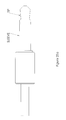
- the plug is shown generally referenced 20, having housing 22.
- the housing includes an opening 24 to allow a lead or cable to be connected to the housing.
- the housing contains one or more magnetic means such as magnets or magnetically permeable material, as discussed above in relation to the socket 1.
- the magnet means is provided rearwardly of contacts 28.
- the upper surface 26 of the plug 20 includes a number of contacts 28.
- the contacts 28 comprise spring contacts i.e. the contacts project beyond surface 26 and are biased outwardly, but capable of being pressed back toward surface 26 on contact with the connector regions of the socket.
- the upper surface 26 also includes one or more alignment means which include contours and such as projecting portions and/or stubs 32.
- the contours 28 can locate about outer surfaces of the peripheral edge 5 of the connector, and the stubs 32 may be provided within the pin receivers 3.
- the stubs 32 could also include some form of communication connection (i.e. include one or more conductors) and/or may also include one or more magnetic means.
- the socket may include conventional functionality including pin receivers 3 for receiving pins of one or more known headset plugs.
- the socket has magnetic areas 42. In a preferred embodiment these comprise permanent magnets (for example rare earth magnets), but in other embodiments may simply be ferromagnetic material for co-acting with a magnet or magnets in similar areas on a plug.
- the apparatus is generally referenced 40 and has a housing 41. Associated with the housing 41 are locating projections 45 and a controllable location projection 46. The function of these features will be described further below.
- a plurality of conductor contact regions arranged in a group 43 in which the contact regions are substantially co-planar is provided. These are shown in more detail in Figure 11 .
- the individual regions are labelled 1 to 10 in that figure and an example of an appropriate function for each electrical contact region in the context of an audio headset is also illustrated in Figure 11 . It can be seen that the individual regions are arranged in three rows, the regions in the first and third rows being substantially aligned with each other, (i.e. regions 1, 2, 3 and 8, 9, 10) and the second or middle row (i.e. regions 4, 5, 6 and 7) has contact regions that are offset from the first and third rows.
- the region bounded by the contact regions 43 has a distinctive shape which may be adapted for receiving a part of the plug, as described further below.
- the shape thus helps to ensure that the plug and the socket can be aligned in only one way and therefore the correct contacts are made between the plug and the socket.
- the shape of the socket places design limitations on the conductor contact regions. In particular the space available is limited. It is cost effective to have the individual conductor regions, and any corresponding pins, as far apart as possible.
- the core functionality terminals should be placed in closest proximity to the largest magnets. This ensures that a strong connection is made at these points and that the audio communication is as clear as possible.
- FIG. 11 a An alternative group 43 of conductor contact regions is shown in Figure 11 a , including an indication of preferred connections for each region provided thereunder. For example, regions 5 and 6 are shown providing connection to right and left audio driver signals, respectively.
- FIG. 11a Passengers in different aircraft cabin classes are often provided with different types of headphones, with differing functionality.
- the arrangement shown in Figure 11a is configured to provide balanced mechanical forces irrespective of the particular connection required to the socket by ensuring that the contact regions used are substantially symmetrical around the centre of the group 43, to the extent practicable.
- Figures 11b - 11 d show the contact regions which are used for different types of connection for different types of headsets.
- Figure 11 b shows the contact regions that may be used for a more conventional stereo headset which may typically be found in economy class areas within an aircraft.
- Figure 11c shows the contact regions that may be used when Active Noise Reduction (ANR) functionality is enabled via region 1.
- Figure 11d shows the contact regions that may be used when powered ANR functionality is provided by a headset. ANR functionality is more typically used in premium flight classes.
- ANR Active Noise Reduction
- the same core functionality is provided via the same core contact regions 5, 6 and 9 positioned substantially centrally within the group 43, with other regions therearound being used as required.
- the pressure on the face of the group 43 is substantially balanced, preventing concentrated / localised forces at the edges of the group.
- the core functionality may be provided by a set of core contact regions placed at each end on the group of conductor regions and substantially balance the pressure on the face of the group.
- the selected regions in figures 29a-c may provide contact regions for a series of different plugs, in one instance these may be a stereo headset, active noise reduction headset and a powered active noise reduction headset.
- the locations of the core contact regions may also be influenced by the position of the magnets, with important signals being placed at the points with the strongest resultant magnetic pulling force.
- the socket is capable of connection with one of a plurality of possible plugs at any one time.
- the plugs may have different electronic pin-outs i.e. pin arrangements.
- the position or location of the pin-outs in the plugs is selected so that plug pins contact the conductor regions which provide the required functionality for any given application.
- the group of conductor regions is arranged so that the pressure on a face of the group of conductor regions is substantially balanced for each of the plurality of pin-outs when the plug and socket are in contact.
- the pins of the plug are preferably spring contacts, biased to project; in a situation where the plug and socket were not balanced so as their faces were substantially parallel this would cause stress on the pins projecting further from the face of the plug, whilst others would be compressed. This increased stress on the pins will cause increased mechanical wear, increased failure rate and additional cost.
- the effect of unbalanced connections on the conductor regions is also undesirable; the pressure difference across the face of the conductor region may also cause unnecessary wear or failure.
- pins/conductor regions are not connected in a balanced manner, such that they remain substantially parallel to each other, it is likely that at least some of the plurality of pins will not have a strong connection with the appropriate conductor region. This may lead to intermittent transfer through the electrical connection or malfunctioning of the device. Further problems may arise when the unbalanced nature of the connections leads to rocking or shaking of the unit. This may become particularly apparent when small, or minimum magnetic fields are used.
- connection between the pins and conductor region is well balanced there is also improved safety as, because the pins and conductor region are substantially parallel and closely connected, there may be less risk of foreign objects or liquids interrupting the connection.
- contact regions While particular inputs / outputs have been shown for the contact regions, the invention is not limited thereto. Further, more or less contact regions may be provided, as desired. For example, without limitation, the contact regions may be configured to interface with a Skype or other IP-based telephony handset or headset or with a USB-type device instead of or in addition to providing the connectivity described above. Other data-type connections are also possible.
- a plug for use with the socket of Figures 8 to 10 is shown in Figures 12 to 14 .
- the plug which is referenced 50, has a cord 53 and has projections 32 if required to assist with alignment with the socket.
- Magnets or magnetic regions 52 are provided to co-act with the magnets or regions 42 of the socket.
- a plurality of pins 51 is arranged in appropriate rows as described with reference to the plurality of contact regions 43 of the socket.
- the array of pins 51 may project slightly as shown in Figure 13 for reception in an appropriately contoured recess of the socket.
- the pins 51 may comprise spring contacts which are biased to project but can move axially back toward the body of the plug upon contact with the socket.
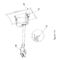
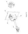
- an armrest 49 such as an aircraft seat armrest, which may include a connector 48 that forms a part of the aircraft or vehicle IFE system.
- the socket 40 is engaged in the armrest and the plug 44 may be engaged with the connector 48.
- FIGs 16 to 19 an installation process for the socket 40 into armrest 49 is illustrated.
- the location projections 45 engage with the lower part of a cutout in the armrest 49.
- the projection 46 is lowered by using an Allen Key or other appropriate tool to rotate projection 46 through use of the tool receiving socket 47. Once the socket 40 is in place, the projection 46 is moved so that it projects from the housing and prevents the socket 40 from being removed from the armrest 49, as shown in Figure 19 .
- FIG. 20 A further embodiment of socket is shown in Figure 20 in which the group 43 of conductor contact regions is has a different physical form, but comprises three rows of conductor contact regions which are provided adjacent to each other in the same plane.
- the group 43 is substantially flush with the surrounding portion of face 4 so that there is no lip or ridge about which dirt or grime can accumulate and thus cause a malfunction.
- Figures 21 and 22 show an arrangement of printed circuit boards 60, 61 and 62 which may be used with an embodiment such as that of Figure 20 .
- Circuit boad 60 has a conductor layer that provides the group 43 of conductor contacts and is machined so that the group 43 protrudes from the remainder of the board. In this way, the housing can be located about the board 60 so that the group 43 is substantially flush with face 4 upon assembly.
- Board 60 also facilitates location of boards 61 and 62 which carry plug pin receivers 3.
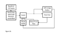
- One problem with the group 43 layout is that short circuiting may occur between the contact regions. For example, a passenger may insert an electrical conductor into the socket. According to one embodiment, this may be overcome by providing a 12v enabling circuit that is not enabled unless a two pole connector is inserted and detected. Such an arrangement is shown in Figure 26 and provides short circuit detection and power enablement.
- a typical 2.5mm audio connector as used on a mobile telephone has a plug with 3 conductors as shown in Figure 25b , namely at the tip, a ring and a sleeve. Between the tip and the sleeve is a driver output and between the ring and the sleeve is a microphone input.
- the circuit of Figure 26 features a front face detection circuit that only enables 12V power output if a power plug (as shown in figure 25a ) is inserted. In this case the ring connection is connected to ground by insertion of the plug and external power is enabled. Power will not be enabled if a 3 or 4 pin 2.5mm plug is detected.
- a liquid spill will not provide a low ohmic connection to ground to enable the switch.
- the conductivity of a liquid is significantly less than that of the dedicated copper short created by connecting the correct magnetic plug.
- the invention provides a front face detection circuit to measure conductivity and enable output voltage appropriately.
- embodiments of the invention provide an over current detection and precision current limit circuit.
- the current limit circuit restricts current flow from the 12V power supply such that no low impedance or short circuit can heat up electronics in the jack or a headphone plug or connected device.
- Embodiments of the invention feature an 'auto recover' current limit that will periodically monitor the current drawn and limit it to a pre-defined level. When the fault condition or short circuit is removed the apparatus will recover and continue normal operation.
- pins whether they are signals or power have independent short circuit protection i.e. all conductive pads and socket terminals are protected in the event of independently being shorted to ground.
- Pin 5 DRIVER RIGHT - Protected by in line resistance.
- Pin 6 DRIVER LEFT - Protected by in line resistance.
- A1 style headphone connections which have a conductive shield or outer
- this connection type is particularly common in high quality stereo headphones.
- the conductive shield or outer of these headphones should be shorted to a ground potential for safe operation of the connector. This can be accomplished by placing the ground conductor regions of the contact regions near or next to the 3.5mm sockets of the connector.
- Passenger liquid spill particular of sugary liquids across the front face could be a source of isolation of the front face pads from plug pins.
- the flush front face can be enabled many ways. A) One way is to use a step control depth routed circuit board located to the rear of the front face. B) Another way is to use plated plastics (likely to be a lower cost method in high volumes).
- the faceplate of the group 43 is elevated to a desired height by mounting thereof on a predetermined number of thicknesses of PCB base material.
- a single PCB board may be partly routed away to provide multiple depths. This is not a frequently used construction technique but can provide the required connectivity between the main circuit boards and the front face which requires a greater area than that of the front face. This is used to protect the main electronics from the customer and only expose the front face.
- Fig 11e shows small exposed contacts on the front and significantly larger contacts on the underside.
- the front face locking has no dedicated key holes or slots. Instead using key holes the holes of the existing ARINC C2 socket for preventing lateral movement, locating and positioning the plug on the front surface. Further the combination of the magnet locations on the front face are such that combined with the existing ARINC connector holes they prevent miss-alignment of the Magnetic plug contacts on the front face conductive pads.
- the magnetic jack is designed using magnets that provide a strong magnetic force (e.g. neodymium or an electromagnet).
- magnets that provide a strong magnetic force (e.g. neodymium or an electromagnet).
- the 3 magnets are all positioned with the same polarity at the face of the socket to ensure the field strength and shape maximise the pull strength with the magnet.
- the contact portions of the plug may simply be formed from a ferrous material rather than both the plug and socket requiring permanent magnets in order to provide the required magnetic strength to effect the coupling such that nuisance disconnects are avoided but disconnects are possible such as when discussed above (eg a user stands or knocks the lead with a tray).
- the magnetic jack can be manufactured to several shapes to fit in existing aircraft seat audio socket cut-outs as it is expensive for airlines to change cut-outs in seats. There are four main seat cut-outs and the jack may be specifically adapted to fit into any of them, including the following: 1401 cut-out, 1406 cut-out.
- 1401 cut-out 1401 cut-out
- 1406 cut-out 1401 cut-out
- magnets and conductive pads within such a small space the shape of the magnets is trapezoid to maximise the magnet size whilst ensuring the magnet is mass manufacturable.
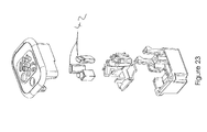
- the magnetic jack is manufactured with a separate magnetic holder such that the magnets are separate and electrically as well as magnetically isolated from the seat, magnets and electronics. This also helps with assembly as the magnets tend to pull themselves together.
- Figures 23 and 24 show an example holder for magnets 42.
- the magnetic are designed and formed to be reverse entry magnets i.e., they are inserted into the apparatus from behind the faceplate of the socket. This helps with assembly and ensures that the magnets do not pull out of the jack with wear and tear.
- PCB plated edges may be used to provide board interconnect. In some cases no pads may be provided on the PCB. This facilitates connection in a small space without the use of the connector.
- the examples described above may be used in conjunction with an in-flight entertainment system - the socket being provided in or adjacent to a passenger seat, and the plug being provided on a headset.
- the socket is intended to have a very long service life.
- Spring contacts which may be used with magnetic jacks by contrast have a limited lifetime.
- the plugs are part of headphones which are viewed by airline operators as a consumable device. Therefore where spring contacts are used they can be located on the plug to maximise the lifetime of the conductive surface of the socket.
- the construction shown has the advantage that multiple contact areas are provided using the layer structure disclosed, so that maximum use is made of the available space and therefore the overall size of the connector and plug arrangement can be kept to a minimum.
- the magnetic connection is advantageously achieved using a magnetic means provided rearwardly of the connector regions i.e. the connector regions in use become between the magnetic means provided in the socket and the plug.
- the socket is provided which may still be used with "legacy" plug arrangements. Therefore, the socket supports a new magnetic plug, but also has the advantage it is functional with existing pin type plug constructions.
Landscapes
- Engineering & Computer Science (AREA)
- Microelectronics & Electronic Packaging (AREA)
- Details Of Connecting Devices For Male And Female Coupling (AREA)
Applications Claiming Priority (1)
| Application Number | Priority Date | Filing Date | Title |
|---|---|---|---|
| US201261612970P | 2012-03-19 | 2012-03-19 |
Publications (1)
| Publication Number | Publication Date |
|---|---|
| EP2642611A1 true EP2642611A1 (de) | 2013-09-25 |
Family
ID=47900929
Family Applications (1)
| Application Number | Title | Priority Date | Filing Date |
|---|---|---|---|
| EP13160067.8A Withdrawn EP2642611A1 (de) | 2012-03-19 | 2013-03-19 | Verbindervorrichtung |
Country Status (2)
| Country | Link |
|---|---|
| US (3) | US9209558B2 (de) |
| EP (1) | EP2642611A1 (de) |
Cited By (3)
| Publication number | Priority date | Publication date | Assignee | Title |
|---|---|---|---|---|
| EP3195413A1 (de) * | 2014-09-12 | 2017-07-26 | IFPL Group Limited | Elektrische steckverbinder |
| CN110380248A (zh) * | 2018-04-13 | 2019-10-25 | 比亚迪股份有限公司 | 电连接器的公头、母头、电连接器、显示终端组件和车辆 |
| TWI790779B (zh) * | 2021-10-14 | 2023-01-21 | 大陸商昆山君磊電器有限公司 | 電機連接器套組 |
Families Citing this family (12)
| Publication number | Priority date | Publication date | Assignee | Title |
|---|---|---|---|---|
| US9209558B2 (en) * | 2012-03-19 | 2015-12-08 | Phitek Systems Limited | Connector apparatus |
| US9620886B1 (en) * | 2013-10-15 | 2017-04-11 | Google Inc. | Electrical connector with recessed contact and socket for receiving electrical connector |
| USD769821S1 (en) * | 2013-10-17 | 2016-10-25 | Phitek Systems Limited | Connector apparatus |
| USD773996S1 (en) * | 2014-04-17 | 2016-12-13 | Phitek Systems Limited | Connector apparatus |
| WO2016176564A1 (en) * | 2015-04-29 | 2016-11-03 | Michael Archuleta | Magnetic coupling for bulbs and sockets |
| US11491884B2 (en) * | 2017-01-19 | 2022-11-08 | Curtis Instruments Inc. | Magnetic charger connector for wheelchair |
| JP6819515B2 (ja) * | 2017-08-29 | 2021-01-27 | トヨタ自動車株式会社 | 車両 |
| EP3773201A1 (de) * | 2018-03-28 | 2021-02-17 | Dexcom, Inc. | Sensorkabelstützvorrichtung mit mechanischen verbindern |
| US11527909B2 (en) | 2018-05-11 | 2022-12-13 | Assembled Products Corporation | Magnetic charging device |
| US10446979B1 (en) * | 2018-07-18 | 2019-10-15 | Prodigit Electronics Co., Ltd. | Power plug adapter with magnetically attachable module |
| US11165205B2 (en) * | 2019-04-19 | 2021-11-02 | Dana Tm4 Inc. | Multi-phase connector for electric powertrain system |
| CN111460698B (zh) * | 2020-01-13 | 2022-11-04 | 北京邮电大学 | 一种连接器插孔应力疲劳下的无源互调预测方法 |
Citations (2)
| Publication number | Priority date | Publication date | Assignee | Title |
|---|---|---|---|---|
| US20040209489A1 (en) * | 2003-04-21 | 2004-10-21 | Clapper Edward O. | Apparatus for automatic docking |
| EP2469663A1 (de) * | 2010-12-24 | 2012-06-27 | Nigel Greig | Magnetisches Verbindungssystem |
Family Cites Families (42)
| Publication number | Priority date | Publication date | Assignee | Title |
|---|---|---|---|---|
| BE790066A (fr) * | 1971-10-14 | 1973-02-01 | Kersman Jorge E | Perfectionnements aux agencements connecteurs a embase |
| US4619495A (en) * | 1982-09-07 | 1986-10-28 | Sochor Jerzy R | High-density press-fit cardedge connectors |
| JPH0834114B2 (ja) | 1987-04-30 | 1996-03-29 | ソニー株式会社 | コネクタ装置 |
| US5015061A (en) | 1987-12-09 | 1991-05-14 | Giannini Gabriel M | Optical connector |
| US4844582A (en) | 1987-12-09 | 1989-07-04 | Giannini Gabriel M | Hybrid electro-optical connectors |
| US5413493A (en) * | 1993-01-15 | 1995-05-09 | Hubbell Incorporated | Electrical connector assembly, especially for electric vehicle |
| JPH09147978A (ja) | 1995-11-29 | 1997-06-06 | Yazaki Corp | 磁石式ロック機構を備えたコネクタ |
| JPH09258072A (ja) | 1996-01-19 | 1997-10-03 | Sony Corp | 光学データ伝送用接続装置 |
| US6616468B2 (en) | 2000-04-17 | 2003-09-09 | Fujikura Ltd. | Connector and electric connection structure |
| US6561827B2 (en) * | 2000-12-18 | 2003-05-13 | Telefonaktiebolaget Lm Ericsson (Publ) | Apparatus for interconnecting multiple nodes |
| US6528746B2 (en) * | 2001-04-27 | 2003-03-04 | Lyall Assemblies, Inc. | Electrical connector system |
| US7021951B2 (en) * | 2002-08-05 | 2006-04-04 | James Tronolone | Self-normalling jack with magnetically controlled normal circuit or relay |
| US7775801B2 (en) | 2005-01-05 | 2010-08-17 | Microsoft Corporation | Device interfaces with non-mechanical securement mechanisms |
| US7311526B2 (en) | 2005-09-26 | 2007-12-25 | Apple Inc. | Magnetic connector for electronic device |
| US7351066B2 (en) | 2005-09-26 | 2008-04-01 | Apple Computer, Inc. | Electromagnetic connector for electronic device |
| US7331793B2 (en) | 2005-12-16 | 2008-02-19 | Motorola, Inc. | Magnetic connector |
| EP1977483A4 (de) | 2006-01-27 | 2011-11-16 | David Robert Goetz | Ablösbares steckverbindersystem |
| US20070254510A1 (en) * | 2006-04-27 | 2007-11-01 | Debey Henry C | Magnetically Retained Electrical Connector |
| JP2007328961A (ja) * | 2006-06-06 | 2007-12-20 | Kyocera Elco Corp | コネクタ装置 |
| US7467948B2 (en) | 2006-06-08 | 2008-12-23 | Nokia Corporation | Magnetic connector for mobile electronic devices |
| US20090192927A1 (en) * | 2006-09-13 | 2009-07-30 | Berg Michel J | Enhanced power outlet system incorporating a smart receptacle |
| US7329128B1 (en) | 2007-01-26 | 2008-02-12 | The General Electric Company | Cable connector |
| TW200840160A (en) | 2007-03-21 | 2008-10-01 | Asustek Comp Inc | Electrical connection mechanism between a body and a base of an electronic device |
| US7722358B2 (en) | 2007-06-15 | 2010-05-25 | Microsoft Corporation | Electrical connection between devices |
| US7566224B2 (en) * | 2007-11-02 | 2009-07-28 | Hon Hai Precision Ind. Co., Ltd. | Electrical connector assembly with magnetic retention device |
| US7497693B1 (en) | 2007-11-30 | 2009-03-03 | Hon Hai Precision Ind. Co., Ltd. | Electrical interconnection system using magnetic retention |
| JP2009158303A (ja) * | 2007-12-26 | 2009-07-16 | Panasonic Electric Works Co Ltd | コンセント、並びに、コンセント及びコンセントプラグ |
| US7762817B2 (en) | 2008-01-04 | 2010-07-27 | Apple Inc. | System for coupling interfacing parts |
| JP5119112B2 (ja) * | 2008-07-30 | 2013-01-16 | 富士通コンポーネント株式会社 | 雄コネクタ、雌コネクタ及びコネクタ |
| TWI382613B (zh) * | 2009-05-04 | 2013-01-11 | Hon Hai Prec Ind Co Ltd | 電連接器 |
| US20140259651A1 (en) * | 2009-05-04 | 2014-09-18 | Nicholas Fletcher | Socket switch |
| WO2011088012A1 (en) | 2010-01-12 | 2011-07-21 | Thales Avionics, Inc. | Break-away connection for in-flight entertainment system |
| US7874844B1 (en) * | 2010-02-02 | 2011-01-25 | Fitts Jr Darrell Lynn | Universal magnetic power supply adaptor |
| CN201927754U (zh) * | 2010-11-16 | 2011-08-10 | 富士康(昆山)电脑接插件有限公司 | 插头连接器及其组合 |
| US8734171B2 (en) * | 2011-04-14 | 2014-05-27 | D Kevin Cameron | Electrical connector having a mechanism for choosing a first or a second power source |
| US8708745B2 (en) * | 2011-11-07 | 2014-04-29 | Apple Inc. | Dual orientation electronic connector |
| CN103682872B (zh) * | 2011-12-24 | 2016-01-06 | 林世峰 | 一种电源连接结构装置 |
| US9209558B2 (en) * | 2012-03-19 | 2015-12-08 | Phitek Systems Limited | Connector apparatus |
| US9190782B2 (en) * | 2012-04-30 | 2015-11-17 | Club Car, Llc | Power connection system |
| US8894419B1 (en) * | 2012-08-14 | 2014-11-25 | Bby Solutions, Inc. | Magnetically connected universal computer power adapter |
| US9004924B2 (en) * | 2013-03-08 | 2015-04-14 | SINGATRON TECHNOLOGY (HongKong) CO., LIMITED | Magnetic power connector and an electronic system using the magnetic power connector assembly |
| US20150236455A1 (en) * | 2014-02-16 | 2015-08-20 | Shenzhen Zhongke Electrical Technology Co., Ltd | Power Supply Connection Structure Device |
-
2013
- 2013-03-19 US US13/847,268 patent/US9209558B2/en active Active - Reinstated
- 2013-03-19 EP EP13160067.8A patent/EP2642611A1/de not_active Withdrawn
-
2015
- 2015-11-19 US US14/945,591 patent/US9660377B2/en active Active
-
2017
- 2017-04-17 US US15/489,555 patent/US20180054023A1/en not_active Abandoned
Patent Citations (2)
| Publication number | Priority date | Publication date | Assignee | Title |
|---|---|---|---|---|
| US20040209489A1 (en) * | 2003-04-21 | 2004-10-21 | Clapper Edward O. | Apparatus for automatic docking |
| EP2469663A1 (de) * | 2010-12-24 | 2012-06-27 | Nigel Greig | Magnetisches Verbindungssystem |
Cited By (3)
| Publication number | Priority date | Publication date | Assignee | Title |
|---|---|---|---|---|
| EP3195413A1 (de) * | 2014-09-12 | 2017-07-26 | IFPL Group Limited | Elektrische steckverbinder |
| CN110380248A (zh) * | 2018-04-13 | 2019-10-25 | 比亚迪股份有限公司 | 电连接器的公头、母头、电连接器、显示终端组件和车辆 |
| TWI790779B (zh) * | 2021-10-14 | 2023-01-21 | 大陸商昆山君磊電器有限公司 | 電機連接器套組 |
Also Published As
| Publication number | Publication date |
|---|---|
| US9660377B2 (en) | 2017-05-23 |
| US20160240965A1 (en) | 2016-08-18 |
| US9209558B2 (en) | 2015-12-08 |
| US20130303001A1 (en) | 2013-11-14 |
| US20180054023A1 (en) | 2018-02-22 |
Similar Documents
| Publication | Publication Date | Title |
|---|---|---|
| US9660377B2 (en) | Connector apparatus | |
| EP2469663B1 (de) | Magnetisches Verbindungssystem | |
| US7270554B2 (en) | Audio jack with plug or head set identification circuit | |
| US9011176B2 (en) | ESD path for connector receptacle | |
| CN205178176U (zh) | 插头电连接器 | |
| US20110189863A1 (en) | Break-away connection for in-flight entertainment system | |
| KR101803823B1 (ko) | 실드를 갖는 커넥터 리셉터클, 커넥터 인서트 및 전자 디바이스 | |
| US7467948B2 (en) | Magnetic connector for mobile electronic devices | |
| EP4324742A2 (de) | Elektrischer verbinder | |
| CN107994403A (zh) | 用于减小长度的连接器插头的接地触点 | |
| US8512048B2 (en) | Expansion device connectable to electronic device | |
| KR101536888B1 (ko) | 자기력으로 고정되는 휴대용 단말기의 충전 장치 | |
| US20100311280A1 (en) | Dual-barrel, connector jack and plug assemblies | |
| TWM519829U (zh) | 耐久連接器插座 | |
| CN109390994B (zh) | 基于pogo连接器的软功率启动解决方案 | |
| CN104505679A (zh) | 一种连接器和一种连接器的实现方法 | |
| EP2538501A1 (de) | Steckverbinder | |
| WO2016038399A1 (en) | Electrical connectors | |
| JP2011171036A (ja) | 電気コネクタ | |
| KR101688333B1 (ko) | 복합 커넥터 장치 | |
| CN109217032A (zh) | 耳机插座组件、电子设备 | |
| JP2008130508A (ja) | 突入電流抑制コネクタ | |
| US11811174B2 (en) | Low-profile axisymmetric power connectors | |
| CN107333388A (zh) | 线路板、电气连接组件以及电子设备 | |
| CN106165214A (zh) | 耳机插口 |
Legal Events
| Date | Code | Title | Description |
|---|---|---|---|
| PUAI | Public reference made under article 153(3) epc to a published international application that has entered the european phase |
Free format text: ORIGINAL CODE: 0009012 |
|
| AK | Designated contracting states |
Kind code of ref document: A1 Designated state(s): AL AT BE BG CH CY CZ DE DK EE ES FI FR GB GR HR HU IE IS IT LI LT LU LV MC MK MT NL NO PL PT RO RS SE SI SK SM TR |
|
| AX | Request for extension of the european patent |
Extension state: BA ME |
|
| 17P | Request for examination filed |
Effective date: 20140325 |
|
| RBV | Designated contracting states (corrected) |
Designated state(s): AL AT BE BG CH CY CZ DE DK EE ES FI FR GB GR HR HU IE IS IT LI LT LU LV MC MK MT NL NO PL PT RO RS SE SI SK SM TR |
|
| 17Q | First examination report despatched |
Effective date: 20150305 |
|
| STAA | Information on the status of an ep patent application or granted ep patent |
Free format text: STATUS: THE APPLICATION IS DEEMED TO BE WITHDRAWN |
|
| 18D | Application deemed to be withdrawn |
Effective date: 20180531 |