EP3773096B1 - Handhabung von küchenmaschinen - Google Patents
Handhabung von küchenmaschinen Download PDFInfo
- Publication number
- EP3773096B1 EP3773096B1 EP19712788.9A EP19712788A EP3773096B1 EP 3773096 B1 EP3773096 B1 EP 3773096B1 EP 19712788 A EP19712788 A EP 19712788A EP 3773096 B1 EP3773096 B1 EP 3773096B1
- Authority
- EP
- European Patent Office
- Prior art keywords
- container
- base
- wall
- seat
- machine
- Prior art date
- Legal status (The legal status is an assumption and is not a legal conclusion. Google has not performed a legal analysis and makes no representation as to the accuracy of the status listed.)
- Active
Links
Images
Classifications
-
- A—HUMAN NECESSITIES
- A47—FURNITURE; DOMESTIC ARTICLES OR APPLIANCES; COFFEE MILLS; SPICE MILLS; SUCTION CLEANERS IN GENERAL
- A47J—KITCHEN EQUIPMENT; COFFEE MILLS; SPICE MILLS; APPARATUS FOR MAKING BEVERAGES
- A47J45/00—Devices for fastening or gripping kitchen utensils or crockery
- A47J45/06—Handles for hollow-ware articles
- A47J45/067—Handles for coffee pots or the like
-
- A—HUMAN NECESSITIES
- A47—FURNITURE; DOMESTIC ARTICLES OR APPLIANCES; COFFEE MILLS; SPICE MILLS; SUCTION CLEANERS IN GENERAL
- A47J—KITCHEN EQUIPMENT; COFFEE MILLS; SPICE MILLS; APPARATUS FOR MAKING BEVERAGES
- A47J41/00—Thermally-insulated vessels, e.g. flasks, jugs, jars
- A47J41/0055—Constructional details of the elements forming the thermal insulation
- A47J41/0061—Constructional details of the elements forming the thermal insulation the elements being detachable or the food holding vessel being replaceable
-
- A—HUMAN NECESSITIES
- A47—FURNITURE; DOMESTIC ARTICLES OR APPLIANCES; COFFEE MILLS; SPICE MILLS; SUCTION CLEANERS IN GENERAL
- A47J—KITCHEN EQUIPMENT; COFFEE MILLS; SPICE MILLS; APPARATUS FOR MAKING BEVERAGES
- A47J43/00—Implements for preparing or holding food, not provided for in other groups of this subclass
- A47J43/04—Machines for domestic use not covered elsewhere, e.g. for grinding, mixing, stirring, kneading, emulsifying, whipping or beating foodstuffs, e.g. power-driven
- A47J43/07—Parts or details, e.g. mixing tools, whipping tools
- A47J43/0716—Parts or details, e.g. mixing tools, whipping tools for machines with tools driven from the lower side
- A47J43/0722—Mixing, whipping or cutting tools
-
- A—HUMAN NECESSITIES
- A47—FURNITURE; DOMESTIC ARTICLES OR APPLIANCES; COFFEE MILLS; SPICE MILLS; SUCTION CLEANERS IN GENERAL
- A47J—KITCHEN EQUIPMENT; COFFEE MILLS; SPICE MILLS; APPARATUS FOR MAKING BEVERAGES
- A47J43/00—Implements for preparing or holding food, not provided for in other groups of this subclass
- A47J43/04—Machines for domestic use not covered elsewhere, e.g. for grinding, mixing, stirring, kneading, emulsifying, whipping or beating foodstuffs, e.g. power-driven
- A47J43/07—Parts or details, e.g. mixing tools, whipping tools
- A47J43/075—Safety devices
- A47J43/0761—Safety devices for machines with tools driven from the lower side
- A47J43/0766—Safety devices for machines with tools driven from the lower side activated by the proper positioning of the mixing bowl
-
- A—HUMAN NECESSITIES
- A47—FURNITURE; DOMESTIC ARTICLES OR APPLIANCES; COFFEE MILLS; SPICE MILLS; SUCTION CLEANERS IN GENERAL
- A47J—KITCHEN EQUIPMENT; COFFEE MILLS; SPICE MILLS; APPARATUS FOR MAKING BEVERAGES
- A47J43/00—Implements for preparing or holding food, not provided for in other groups of this subclass
- A47J43/04—Machines for domestic use not covered elsewhere, e.g. for grinding, mixing, stirring, kneading, emulsifying, whipping or beating foodstuffs, e.g. power-driven
- A47J43/046—Machines for domestic use not covered elsewhere, e.g. for grinding, mixing, stirring, kneading, emulsifying, whipping or beating foodstuffs, e.g. power-driven with tools driven from the bottom side
- A47J43/0465—Machines for domestic use not covered elsewhere, e.g. for grinding, mixing, stirring, kneading, emulsifying, whipping or beating foodstuffs, e.g. power-driven with tools driven from the bottom side with magnetic drive
Definitions
- the field of the invention pertains to machines for processing a food substance, such as milk or a milk-containing substance, having a food processing receptacle with a handle.
- the machine is provided with an impeller and/or a thermal management arrangement.
- the best-known beverage of this type is a coffee of the cappuccino type. It comprises a liquid portion consisting of coffee topped by a layer of frothed milk which, because of its very much lower density, floats atop the surface of the liquid. In general, preparing one takes time, manipulation operations and cleaning.
- Milk-based froth can be prepared in a mechanical stirring appliance. Regular cleaning of the tank of the appliance needs to be envisaged in order to remove any solid food residue. In addition, heating the milk has a tendency to increase the extent to which cooked or burnt proteins are deposited on and adhere to the surfaces.
- US Patent 6,318,247 relates to an appliance for preparing hot beverages or food with stirring such as hot chocolate, for example.
- Other devices for stirring food products are described in patent documents WO 2004/043213 or DE 196 24 648 .
- Stirring systems with a magnetic engagement type are described in documents US 2,932,493 , DE 1 131 372 , US 4,537,332 and US 6,712,497 .
- DE 89 15 094 relates to a refrigerated pot for dispensing a milk-based beverage.
- US Patent 3,356,349 discloses a stirring device that has a heated tank, magnetic drive means positioned under the tank for driving a hub located in the middle of the tank.
- beverage processing appliances using stirring systems in particular magnetically driven stirring systems, are disclosed in WO 2016/202814 , WO 2016/202815 , WO 2016/202816 , WO 2016/202817 , PCT/EP17/082208 and PCT/EP17/082211 .
- the device has: an inner tank for receiving the liquid that is to be frothed, in which a rotatable stirrer is positioned; an outer stand holding the tank; drive and control means which are in a cavity located between the inner tank and the outer stand, and which communicate with a switch and electrical connections located on the outer surface of the stand; and disturbance means to optimise circulation of the milk during frothing.
- Heat can be provided into the processing tank by using an induction system, e.g. as disclosed in EP2017203199 .
- the abovementioned EP2017203199 and WO 2017/216133 discloses a beverage processing tank.
- the beverage can be heated in the tank.
- the tank is fitted with a handle that has a connection member projecting from the tank and a generally upright elongated gripping part extending above and below the connection member.
- the invention thus relates to a machine for processing a liquid food substance, such as milk or a milk-based substance.
- the liquid food substance can be aqueous, e.g. containing coffee and/or chocolate and/or cacao.
- the machine may be a standalone machine, e.g. directly pluggable to the mains via an electric cord, or may be integrated in a food processor arranged to process other food items or to carry out different food conditioning processes, the food processor itself being generally pluggable to the mains via an electric cord whereas the machine is a sub-part of the food processor.
- a food processor may be a beverage maker, such as a coffee maker, e.g. a beverage maker configured to prepare a beverage (such as coffee) from an ingredient capsule.
- the machine of the invention may advantageously be configured to froth and/or heat and/or cool milk and optionally be associated, as a standalone machine or as an integrated machine, into a coffee maker.
- Standalone machines and integrated associations of milk frothing machines and coffee makers are for example disclosed in WO 2006/050900 , WO 2008/142154 , WO 2009/074555 , WO 2010/023312 and WO 2010/023313 .
- the machine can be a milk frother which operates by incorporating finely divided gas bubbles, e.g. air bubbles, into milk.
- gas bubbles e.g. air bubbles
- the machine When the machine is configured for incorporating gas bubbles into milk, it may include an operating mode without incorporation of gas bubbles.
- the machine of the invention is configured for processing a liquid food substance, such as milk or a milk-based substance
- the container can be substantially cup-shaped or bowl-shaped or cylinder-shaped, the sidewall being substantially upright and the bottom wall being substantially flat or curved.
- the jug may be mechanically passive. Hence, beyond the inherent mechanical properties of the materials making its structure for containing the food substance and for being integrated or assembled in the machine, the jug may be free of any mechanically active part such as a motor or movement transformation system which may require special care for hygiene or cleaning purposes.
- the jug may contain one or more mechanically passive movable parts, such as a whisk or stirrer or ingredient basket in the container, that is/are driven from outside the jug.
- the jug may be electrically passive. Hence, beyond the inherent electrical properties (e.g. resistive and/or inductive and/or capacitive properties) of the materials making its structure for containing the food substance and for being integratable or assembled in the machine, the jug may be free of any electric components, in particular active electric components. The inherent electrical properties of the jug may however be used in the processing of the food substance, for instance for heating and/or cooling the jug that is powered electrically or electromagnetically from an (active) source that is external to the jug.
- an (active) source that is external to the jug.
- a jug which is mechanically and/or electrically passive (optionally with a lid that is equally passive), it can easily be cleaned, e.g. in a dishwater, without any risk of damaging electric and/or mechanic components.
- the jug is provided with a control cavity, e.g. containing mechanical and/or electric control active constituents such as actuators and signal processing units, which cavity has no movable access panel sealed off by a rubber, silicone or like seal that is exposed to early wear, especially when exposed to detergents or soaps used for cleaning.
- a control cavity e.g. containing mechanical and/or electric control active constituents such as actuators and signal processing units
- the jug contains active components that are contained in an inaccessible confinement cavity, the jug being for instance entirely moulded and/or welded around such a confinement cavity so that the cavity is completely sunk in the jug's structure and separate from the environment outside the jug with no access from the outside without destroying the jug.
- the jug may contain in such confined inaccessible cavity an active device, e.g. an RFID-type device or the like.
- the machine may have a base that has one or more walls forming a seat for removably receiving the container.
- Actuators e.g. motors, control units, user-interfaces, AC/DC converters can all be comprised in the base, e.g. in the powered cavity.
- the handle has a connection member projecting from the container and a substantially elongated upright gripping member that is connected to the connection member at a distance from the container.
- the gripping member has an upper portion that is above the connection member and a lower portion that is below the connection member.
- the upper portion is configured to support a thumb of the hand and delimits with the connection member an upper seat for accommodating an index finger of the hand when the handle is held by the hand.
- connection member may be horizontal or at an angle of less than 30 deg thereto, such as less than 15 deg. thereto, when the jug is oriented for processing the liquid food substance.
- the upright gripping member may extend vertically or at an angle of less than 30 deg thereto, such as less than 15 deg. thereto.
- the handle has a confinement member that extends: substantially uprightly between the container and the lower portion of the gripping member; and downwardly from the connection member or from close thereto.
- the confinement member may be spaced (if at all) from the connection member by a distance of less than 5 mm.
- the confinement member and the lower portion and the connection member delimit a lower seat for accommodating a portion of a middle finger of the hand when the handle is held by the hand.
- such a handle configuration may be used to safely secure the handle (and the jug) between the inner side of the hand's thumb (pushing the handle's upper portion towards the container), the inner side of a hand's first finger below the thumb (e.g. the index finger pulling the handle's upper portion away from the container) and the rear and lateral sides of a hand's second finger (e.g. the hand's middle finger resting against the confinement member towards the container and supporting the connection member).
- the jug is held by the second finger and locked in position by the thumb and the first finger in an ergonomic manner.
- the remaining fingers e.g.
- the annular and the little fingers are not even required for holding or securing the jug in the user's hand. If the lower portion of the gripping member is long enough, these remaining fingers may seize it to assist the holding. However, such a contribution by the remaining fingers is optional.
- the confinement member may be used to reduce the risk that the hand comes into contact with heated or cooled parts of the container, for instance when the container is heated above 40°C or 50°C or cooled down below 10°C or 5°C.
- the confinement member may thus be spaced from the container and/or made of thermally insulating material, e.g. a ceramic and/or a polymer.
- the upper part may be spaced from the container by a distance in the range of 1.5 to 4 cm, such as 2 to 3 cm.
- the upper part can extend above the connection member by a distance in the range of 1 to 3 cm, such as 1.5 to 2.5 cm.
- the upper part of the gripping member may have a width in the range of 0.5 to 3 cm, such as 1 to 2 cm.
- the upper part can have an uppermost free end.
- the lower part of the gripping member can be spaced from the container by a distance in the range of 1.5 to 4 cm, such as 2 to 3 cm.
- the lower part may extend below the connection member by a distance in the range of 1 to 5 cm, such as 2.5 to 4.5 cm.
- the lower part of the gripping member can have a width in the range of 0.5 to 3 cm, such as 1 to 2 cm.
- the confinement member may be spaced by a distance to the lower part of the gripping part in the range of 1.5 to 3 cm, such as 2 to 2.5 cm.
- the confinement member can have a lowermost end that is spaced by a distance to the connection member in the range of 0.5 to 5 cm such as 1 to 3 cm, e.g. 1.5 to 2.5 cm.
- the confinement member may have a width in the range of 0.5 to 3 cm, such as 1 to 2 cm.
- the confinement member can have a lowermost free end.
- the removable lid can extend over the rim and have an upright inner wall that extends downwardly into the cavity along the rim.
- the peripheral wall and/or the upright inner wall has a sealing member, such as an annular deformable sealing member, for sealing off the cavity of the container.
- a sealing member such as an annular deformable sealing member
- the removable lid can have a or the above peripheral wall that has a bottom end that contacts or comes close to the connection member.
- the bottom end is spaced from the connection member by less than 1 cm, such as less than 0.5 cm.
- the cavity of the container may extend to above the connection member by a height in the range of 1 to 7 cm, such as from 2 to 5 cm, e.g. from 3 to 4 cm.
- the base may delimit a peripheral seat, such as a peripheral seat on a or the above outside face of the base, for receiving the confinement member when the container is received by the seat of the base so as to be in place for processing the liquid food substance.
- a peripheral seat such as a peripheral seat on a or the above outside face of the base
- the cooperating member and peripheral seat may be used to prevent relative movement of the jug and seat during the processing of the liquid food substance.
- the cooperating member and peripheral seat can also be used to detect automatically a misplacement of the jug and seat such that the processing of the liquid food substance is not possible or sub-optimal.
- such a misplacement may be detected automatically by using a sensor for sensing the presence (or absence) of the member in the cooperating peripheral seat.
- a sensor for sensing the presence (or absence) of the member in the cooperating peripheral seat.
- such a sensor is not required to detect automatically a misplacement, for example as exposed in the embodiments below.
- the seat and the confinement member have at least one of:
- the container may be off its place for processing the liquid food substance when the confinement member is off-set, e.g. angularly off-set, relative to the peripheral seat.
- the machine may include a processing device and a control system that is configured to control the processing device, such as an actuator and/or a thermal conditioner controlled by a control unit, for processing the liquid food substance.
- the control system can be configured to detect when the container is off its processing place by measuring a characteristic, e.g. a current consumption and/or a voltage consumption and/or an electric frequency, of the processing device and comparing such measured characteristic to an expected value thereof when the container is in its processing place or off its processing place.
- the control system may be configured to prevent processing of the liquid food substance and/or generate an error message or alarm, when the control system detects that the container is off its processing place.
- the container may have at least one outside container wall that can be thermally conditioned by the liquid food substance in the cavity and/or by processing the liquid food substance in the cavity and that faces the base wall (s) when the container is in or on the base seat.
- the base and/or the container can have one or more thermally insulating spacers, such as ribs or protrusions or an insulating layer, spacing the base wall(s) from the container wall(s) when the container is received in or on the seat so as to prevent or inhibit thermal transfer between the base wall(s) and the container wall (s) adjacent the base wall(s).
- the container may include an outside thermally radiating or absorbing element, such as an electrically resistive element or a thermocouple element.
- the outside thermally radiating or absorbing element may have a total outside surface facing the base wall(s), whereby less than 15%, such as less than 10%, for example less than 5%, e.g. less than 3%, of the total outside surface contacts or forms the thermally insulating spacers.
- Such insulating spacer may be made of insulating material, such as a ceramic or polymer material, and/or the spacer may have an insulating shape, e.g. provided with a small cross-section orthogonal to the thermal flux between the container and the base.
- the thermally radiating or absorbing element may be powered by the base by electric conduction and/or electromagnetic induction.
- the energy may be passed inductively from the base to the jug by an induction generation device in the base and by an induction receiver in the jug, e.g. walls of the container.
- the container can be configured to radiate heat to outside of the container or absorb heat from outside of the container predominantly via one or more preferential container walls, that form such (a) thermally radiating or absorbing element(s), when the liquid food substance is processed in the container received in or on the seat.
- the thermally insulating spacers can be positioned so as to space the preferential wall(s) from the base wall(s).
- the preferential container wall(s) may form a bottom wall of the container or a sidewall of the container or both.
- the or each insulating spacer may be configured to space the corresponding base wall from the container wall by a distance in the range of 0.1 to 1 cm, such as 0.3 to 0.8 e.g. 0.4 to 0.7 cm.
- the food cavity contains a movable agitating device, such as a whisk and/or a stirrer, to agitate the liquid food substance during its processing.
- a movable agitating device such as a whisk and/or a stirrer
- the agitating element is:
- the agitating device may be an impeller.
- the impeller may have a spring-like structure of the type disclosed in WO 2006/050900 or in WO 2008/142154 and/or the impeller can have a wavy and/or open disc-shaped structure as taught in WO 2016/202817 .
- the impeller can have a foot for being coupled to the actuator, e.g. via magnetic elements in the foot.
- a magnetic coupling of the impeller e.g. of a low inertia impeller, can be achieved as taught in WO 2006/050900 or in WO 2008/142154 .
- the magnetic coupling of the impeller e.g. of a high inertia impeller, may be achieved as taught in WO 2016/202814 or PCT/EP17/082211 .
- Suitable impellers and their implementation into the machine are disclosed in WO 2016/202814 , WO 2016/202815 , WO 2016/202816 and WO 2016/202817 as well as PCT/EP17/082208 and PCT/EP17/082211 .
- the container can be provided with a thermally insulating outside material and/or with a handle, for seizure and optional displacement of the container by a human hand.
- a thermally insulating outside material and/or with a handle, for seizure and optional displacement of the container by a human hand.
- Such a configuration is particularly advantageous when the food is processed at a higher temperature exceeding e.g. 50°C or at lower temperature below 10°C.
- orientation or position When reference is made in the present description to an orientation or position relative to the machine or parts thereof, e.g. “above” or “below” or “vertical” or “horizontal”, the orientation or position takes as a reference the position and orientation of the machine in operation to process the liquid food substance in the container unless specified otherwise.
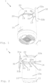
- FIG. 1 An exemplary embodiment of a machine 1 according to the invention and parts thereof are illustrated in Figs 1 to 6 .
- Machine 1 is configured for processing a liquid food substance, such as milk or a milk-based substance.
- Machine 1 includes a jug 20 having a container 21 and a handle 31,32,33 for holding jug 20 by an adult human hand 40.
- Container 21 delimits a food cavity 21' for containing the liquid food substance.
- Container 21 may have a removable lid 22 for covering cavity 21' ( Figs 1, 2 and 4 ).
- Food cavity 21' may have a central upright or vertical axis 21".
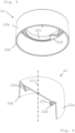
- Machine 1 may incorporate a base 10 that has one or more walls 11 forming a seat 11' for removably receiving container 21 ( Fig. 3 ).
- handle 31,32,33 can have a connection member 31 projecting from container 21 and a substantially elongated upright gripping member 32 that is connected to connection member 31 at a distance from container 21.
- Gripping member 32 has an upper portion 32a that is above connection member 31 and a lower portion 32b that is below the connection member 31.
- Upper portion 32a is configured to support a thumb 41 of hand 40 and delimits with connection member 31 an upper seat 31a for accommodating an index finger 42 of hand 40 when handle 31,32,33 is held by hand 40.
- Connection member 31 can be horizontal or at an angle of less than 30 deg thereto, such as less than 15 deg. thereto, when jug 20 is oriented for processing liquid food substance.
- Upright gripping member 32 may extend vertically or at an angle of less than 30 deg thereto, such as less than 15 deg. thereto.
- Handle 31,32,33 has a confinement member 33 that extends: substantially uprightly between the container 21 and lower portion 32b of gripping member 32; and downwardly from connection member 31 or from close thereto.
- Confinement member 33 and lower portion 32b and connection member 31 may delimit a lower seat 31b for accommodating a portion of a middle finger 43 of hand 40 when handle 31,32,33 is held by hand 40.
- such a handle configuration may be used to safely secure handle 31,32,33 between the inner side of the hand's thumb 41 (pushing in a direction 41a the handle's upper portion 32a towards container 21), the inner side of a hand's first finger 42 below the thumb 41 (e.g. the index finger 42 pulling in a direction 42a the handle's upper portion 32a away from container 21) and the rear and lateral sides of a hand's second finger 43 (e.g. the hand's middle finger 43 resting against confinement member 33 towards container 21 and supporting connection member 31 in a direction 43a).
- jug 20 is held by second finger 43 and locked in position by thumb 41 and first finger 42 in an ergonomic manner.
- the remaining fingers 44 e.g. the annular and the little fingers 44, are not even required for holding or securing jug 20 in the user's hand. If the lower portion 32a of the gripping member 32 is long enough, these remaining fingers 44 may seize it to assist the holding (in a direction 44a). However, such a contribution by the remaining fingers is optional.
- Upper part 32a of gripping member 32 may have at least one of the following features: upper part 32a can be spaced from container 21 by a distance in the range of 1.5 to 4 cm, such as 2 to 3 cm; upper part 32a may extend above connection member 31 by a distance in the range of 1 to 3 cm, such as 1.5 to 2.5 cm; upper part 32a of gripping member 32 can have a width in the range of 0.5 to 3 cm, such as 1 to 2 cm; and upper part 32a can have an uppermost free end.
- Lower part 32b of gripping member 32 may have at least one of the following features: lower part 32b can be spaced from container 21 by a distance in the range of 1.5 to 4 cm, such as 2 to 3 cm; lower part 32b may extend below connection member 31 by a distance in the range of 1 to 5 cm, such as 2.5 to 4.5 cm; lower part 32b of gripping member 32 can have a width in the range of 0.5 to 3 cm, such as 1 to 2 cm; and lower part 32b may have a lowermost free end.
- Confinement member 33 may have at least one of following features: confinement member 33 can be spaced by a distance to lower part 32b of gripping part 32 in the range of 1.5 to 3 cm, such as 2 to 2.5 cm; confinement member 33 can have a lowermost end that is spaced by a distance to connection member 31 in the range of 0.5 to 5 cm such as 1 to 3 cm, e.g. 1.5 to 2.5 cm; confinement member 33 may have a width in the range of 0.5 to 3 cm, such as 1 to 2 cm; and confinement member 33 can have a lowermost free end.
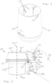
- container 20 may have a rim 22' delimiting an opening of container cavity 21', removable lid 22 extending over rim 22'.
- lid 22 can have a peripheral wall 22a that extends downwardly to form an outside lid face of container 21, such as an outside lid face: having a height in the range of 0.5 to 5 cm e.g. in the range of 1.5 to 3.5 cm; and/or extending flush with an outside face 20a of container 21 uncovered by lid 22 and/or with an outside face 10a of base 10.
- Lid 22 may have an upright inner wall 22c that extends downwardly into cavity 21' along rim 22'.
- Peripheral wall 22a and/or upright inner wall 22c can have a sealing member 22d, such as an annular deformable sealing member, for sealing off cavity 21'.
- Sealing member 22d may have one or more substantially parallel sealing lips 22e, such as annular lips arranged side-by-side.
- Sealing member 22d can have a tab 22f for seizing sealing member 22e.
- Sealing member 22d may be removable from lid 22, for instance for cleaning, and mountable on lid 22.
- Removable lid 22 can have a or the above peripheral wall 22a that has a bottom end 22b that contacts or comes close to connection member 31. Bottom end 22b can be spaced from connection member 31 by less than 1 cm, such as less than 0.5 cm.
- Cavity 21' of container 21 may extend to above connection member 31 by a height in the range of 1 to 7 cm, such as from 2 to 5 cm, e.g. from 3 to 4 cm.
- base 10 can delimit a peripheral seat 13, such as a peripheral seat 13 on a or the above outside face 10a of base 10, for receiving confinement member 33 when container 21 is received by seat 11' of base 10 such that container 21 is in place for processing the liquid food substance.
- a peripheral seat 13 such as a peripheral seat 13 on a or the above outside face 10a of base 10
- seat 13 and confinement member 33 can have at least one of: complementary shapes so that base 10 and confinement member 33 form together a continuous outside surface; an arrangement to prevent a rotation of container 21 relative to base 10; and an arrangement such that a downwardly oriented edge 34 of container 21 rests on an upwardly oriented edge 14 of base 10 or such that container edge 34 is distant to base edge 14 by no more than 0.5 mm, base edge 14 forming for instance a rim of base seat 11 for receiving container 21.
- Container 21 may be off its place for processing the liquid food substance when confinement member 33 is off-set, e.g. angularly off-set, relative to peripheral seat 13, as illustrated in Fig. 2 .
- a or the above downwardly oriented edge 34 of container 21 may be spaced apart from an or the above upwardly oriented edge 14 of base 10, such as a base edge 14 forming a rim of base seat 11 for receiving container 21, by a distance that is greater than when confinement member 33 is received in peripheral seat 13.
- Machine 1 may include a processing device and a control system that is configured to control the processing device, such as an actuator and/or a thermal conditioner controlled by a control unit, for processing the liquid food substance.
- the control system can be configured to detect when container 21 is off its processing place by measuring a characteristic, e.g. a current consumption and/or a voltage consumption and/or an electric frequency, of the processing device and comparing such measured characteristic to an expected value thereof when container 21 is in its processing place or off its processing place.
- a characteristic e.g. a current consumption and/or a voltage consumption and/or an electric frequency
- Container 21 may have at least one outside container wall 21a that can be thermally conditioned by the liquid food substance in cavity 21' and/or by processing the liquid food substance in cavity 21' and that faces base wall (s) 11 when container 21 is in or on base seat 11'.
- base 10 and/or container 21 may include one or more thermally insulating spacers 11a, such as ribs or protrusions or an insulating layer, spacing base wall(s) 11 from container wall(s) 21a when container 21 is received in or on seat 11' so as to prevent or inhibit thermal transfer between base wall(s) 11 and container wall(s) 21a.
- Container 21 may include a thermally radiating or absorbing element, such as an electrically resistive element or a thermocouple element.
- the thermally radiating or absorbing element is powered by base 10 by electric conduction and/or electromagnetic induction.
- Container 21 can be configured to radiate heat to outside of container 21 or absorb heat from outside of container 21 predominantly via one or more preferential container walls 21a, as the above thermally radiating or absorbing element, when the liquid food substance is processed in container 21 received in or on seat 11'.
- Thermally insulating spacers 11a may be positioned so as to space preferential wall(s) 21a from base wall(s) 11.
- preferential container wall(s) 21a form a bottom wall 23 of container 21 or a sidewall of container 21 or both.
- the or each insulating spacer 11a may be configured to space the corresponding base wall 11 from container wall 21a by a distance in the range of 0.1 to 1 cm, such as 0.3 to 0.8 e.g. 0.4 to 0.7 cm.
- Base 10 may have a powered cavity, e.g. a cavity powered by the mains via an electric cord 15, that is adjacent container 21.
- the base cavity may include a thermal conditioner for generating heat in food cavity 21' (heating the cavity) and/or for removing heat from food cavity 21' (cooling the cavity).
- Food cavity 21' may contain a movable agitating device, such as a whisk and/or a stirrer, to agitate the liquid food substance during its processing.
- the agitating element may be:
Landscapes
- Engineering & Computer Science (AREA)
- Food Science & Technology (AREA)
- Mechanical Engineering (AREA)
- Physics & Mathematics (AREA)
- Thermal Sciences (AREA)
- Food-Manufacturing Devices (AREA)
- Cookers (AREA)
Claims (15)
- Maschine (1) zum Verarbeiten einer flüssigen Lebensmittelsubstanz, wie Milch oder einer milchbasierten Substanz, umfassend:- eine Kanne (20), die einen Behälter (21) und einen Griff (31, 32, 33) zum Halten der Kanne durch eine erwachsene menschliche Hand (40) aufweist, wobei der Behälter (21) einen Lebensmittelhohlraum (21') zum Enthalten der flüssigen Lebensmittelsubstanz abgrenzt, wie einen Behälter (21), der einen abnehmbaren Deckel (22) zum Abdecken des Hohlraums (21') aufweist; und wahlweise- eine Basis (10), die eine oder mehrere Wände (11) aufweist, die einen Sitz (11') zum abnehmbaren Aufnehmen des Behälters (21) bilden,wobei der Lebensmittelhohlraum (21') eine bewegbare Rührvorrichtung, wie einen Schneebesen und/oder einen Rührer, enthält, um die flüssige Lebensmittelsubstanz während ihrer Verarbeitung zu rühren,wobei der Griff (31, 32, 33) ein Verbindungsglied (31), das aus dem Behälter (21) vorsteht, und ein im Wesentlichen langgestrecktes aufrechtes Greifglied (32) aufweist, das mit dem Verbindungsglied (31) in einer Entfernung von dem Behälter (21) verbunden ist, wobei das Greifglied (32) einen oberen Abschnitt (32a), der oberhalb des Verbindungsglieds (31) ist, und einen unteren Abschnitt (32b) aufweist, der unterhalb des Verbindungsglieds (31) ist, wobei der obere Abschnitt (32a) konfiguriert ist, um einen Daumen (41) der Hand (40) zu stützen, und mit dem Verbindungsglied (31) einen oberen Sitz (31a) zum Beherbergen eines Zeigefingers (42) der Hand (40) abzugrenzen, wenn der Griff (31, 32, 33) durch die Hand (40) gehalten wird, wobei wahlweise:- das Verbindungsglied (31) horizontal oder in einem Winkel von weniger als 30 Grad dazu, wie weniger als 15 Grad dazu, ist, wenn die Kanne (20) zum Verarbeiten der flüssigen Lebensmittelsubstanz ausgerichtet ist; und/oder- sich das aufrechte Greifglied vertikal oder in einem Winkel von weniger als 30 Grad dazu, wie weniger als 15 Grad dazu, erstreckt,dadurch gekennzeichnet, dass der Griff (31, 32, 33) ein Einschlussglied (33) aufweist, das sich erstreckt:- im Wesentlichen aufrecht zwischen dem Behälter (21) und dem unteren Abschnitt (32b) des Greifglieds (32); und- nach unten von dem Verbindungsglied (31) oder aus einer Nähe davon,wobei das Einschlussglied (33) und der untere Abschnitt (32b) und das Verbindungsglied (31) einen unteren Sitz (31b) zum Beherbergen eines Abschnitts eines Mittelfingers (43) der Hand (40) abgrenzen, wenn der Griff (31, 32, 33) durch die Hand (40) gehalten wird.
- Maschine nach Anspruch 1, wobei der obere Teil (32a) des Greifglieds (32) mindestens eines der folgenden Merkmale aufweist:- der obere Teil (32a) ist von dem Behälter (21) um eine Entfernung in dem Bereich von 1,5 bis 4 cm, wie 2 bis 3 cm, beabstandet;- der obere Teil (32a) erstreckt sich oberhalb des Verbindungsglieds (31) um eine Entfernung in dem Bereich von 1 bis 3 cm, wie 1,5 bis 2,5 cm;- der obere Teil (32a) des Greifglieds (32) weist eine Breite in dem Bereich von 0,5 bis 3 cm, wie 1 bis 2 cm, auf; und- der obere Teil (32a) weist ein oberstes freies Ende auf.
- Maschine nach Anspruch 1 oder 2, wobei der untere Teil (32b) des Greifglieds (32) mindestens eines der folgenden Merkmale aufweist:- der untere Teil (32b) ist von dem Behälter (21) um eine Entfernung in dem Bereich von 1,5 bis 4 cm, wie 2 bis 3 cm, beabstandet;- der untere Teil (32b) erstreckt sich unterhalb des Verbindungsglieds (31) um eine Entfernung in dem Bereich von 1 bis 5 cm, wie 2,5 bis 4,5 cm;- der untere Teil (32b) des Greifglieds (32) weist eine Breite in dem Bereich von 0,5 bis 3 cm, wie 1 bis 2 cm, auf; und- der untere Teil (32b) weist ein unterstes freies Ende auf.
- Maschine nach einem der vorstehenden Ansprüche, wobei das Einschlussglied (33) mindestens eines der folgenden Merkmale aufweist:- das Einschlussglied (33) ist um eine Entfernung zu dem unteren Teil (32b) des Greifabschnitts (32) in dem Bereich von 1,5 bis 3 cm, wie 2 bis 2,5 cm, beabstandet;- das Einschlussglied (33) weist ein unterstes Ende auf, das um eine Entfernung zu dem Verbindungsglied (31) in dem Bereich von 0,5 bis 5 cm, wie 1 bis 3 cm, z. B. 1,5 bis 2,5 cm, beabstandet ist;- das Einschlussglied (33) weist eine Breite in dem Bereich von 0,5 bis 3 cm, wie 1 bis 2 cm, auf; und- das Einschlussglied (33) weist ein unterstes freies Ende auf.
- Maschine nach einem der vorstehenden Ansprüche, wobei der Behälter (20) eine Kante (22'), die eine Öffnung des Behälterhohlraums (21') abgrenzt, aufweist, wobei sich der abnehmbare Deckel (22) über die Kante (22') erstreckt und mindestens eines aufweist von:a) einer peripheren Wand (22a), die sich nach unten erstreckt, um eine äußere Deckelfläche des Behälters (21) zu bilden, wie eine äußere Deckelfläche:- die eine Höhe in dem Bereich von 0,5 bis 5 cm, z. B. in dem Bereich von 1,5 bis 3,5 cm, aufweist; und/oder- die sich bündig mit einer äußeren Fläche (20a) des Behälters (21), die nicht durch den Deckel (22) abgedeckt ist, und/oder mit einer äußeren Fläche (10a) der Basis (10) erstreckt,
undb) einer aufrechten Innenwand (22c), die sich nach unten in den Hohlraum (21') entlang der Kante (22') erstreckt,
wobei wahlweise die periphere Wand (22a) und/oder die aufrechte Innenwand (22c) ein Dichtungsglied (22d), wie ein ringförmiges verformbares Dichtungsglied, zum Abdichten des Hohlraums (21') aufweist, zum Beispiel ein solches Dichtungsglied (22d), das mindestens eines der folgenden Merkmale aufweist:- das Dichtungsglied (22d) weist eine oder mehrere im Wesentlichen parallele Dichtungslippen (22e), wie ringförmige Lippen, auf, die nebeneinander angeordnet sind;- das Dichtungsglied (22d) weist eine Lasche (22f) zum Fassen des Dichtungsglieds (22e) auf; und- das Dichtungsglied (22d) ist von dem Deckel (22) abnehmbar, zum Beispiel zum Reinigen, und an dem Deckel montierbar. - Maschine nach einem der vorstehenden Ansprüche, wobei der abnehmbare Deckel (22) eine oder mehrere periphere Wände (22a) aufweist, die ein Bodenende (22b) aufweisen, das das Verbindungsglied (31) berührt oder diesem nahe kommt, wobei wahlweise das Bodenende (22b) um weniger als 1 cm, wie weniger als 0,5 cm, von dem Verbindungsglied (31) beabstandet ist.
- Maschine nach einem der vorstehenden Ansprüche, wobei sich der Hohlraum (21') des Behälters (21) bis oberhalb des Verbindungsglieds (31) um eine Höhe in dem Bereich von 1 bis 7 cm, wie von 2 bis 5 cm, z. B. von 3 bis 4 cm, erstreckt.
- Maschine nach einem der vorstehenden Ansprüche, wobei die Basis (10) einen peripheren Sitz (13), wie einen peripheren Sitz (13) an einer oder der äußeren Fläche (10a) der Basis (10), zum Aufnehmen des Einschlussglieds (33) abgrenzt, wenn der Behälter (21) durch den Sitz (11') der Basis (10) aufgenommen wird, derart, dass der Behälter (21) zum Verarbeiten der flüssigen Lebensmittelsubstanz an einem Platz ist, wobei wahlweise, wenn das Begrenzungsglied (33) in dem peripheren Sitz (13) aufgenommen wird, der Sitz (13) und das Einschlussglied (33) mindestens eines aufweisen von:- komplementären Formen, sodass die Basis (10) und das Einschlussglied (33) zusammen eine durchgehende äußere Oberfläche bilden;- einer Anordnung, um eine Drehung des Behälters (21) relativ zu der Basis (10) zu vermeiden; und- einer Anordnung derart, dass ein nach unten gerichteter Rand (34) des Behälters (21) auf einem nach oben gerichteten Rand (14) der Basis (10) ruht oder derart, dass der Behälterrand (34) um nicht mehr als 0,5 mm von dem Basisrand (14) entfernt ist, wobei der Basisrand (14) zum Beispiel eine Kante des Basissitzes (11) zum Aufnehmen des Behälters (21) bildet.
- Maschine nach Anspruch 8, wobei sich der Behälter (21) abseits von seinem Platz zum Verarbeiten der flüssigen Lebensmittelsubstanz befindet, wenn das Einschlussglied (33) relativ zu dem peripheren Sitz (13) versetzt ist, z. B. winkelversetzt.
- Maschine nach Anspruch 9, wobei ein oder der nach unten gerichtete Rand (34) des Behälters (21) von einem oder dem nach oben gerichteten Rand (14) der Basis (10), wie einem Basisrand (14), der eine Kante der Basisaufnahme (11) zum Aufnehmen des Behälters (21) bildet, um eine Entfernung beabstandet ist, die größer ist als wenn das Einschlussglied (33) in dem peripheren Sitz (13) aufgenommen ist.
- Maschine nach Anspruch 9 oder 10, die eine Verarbeitungsvorrichtung und ein Steuersystem umfasst, das konfiguriert ist, um die Verarbeitungsvorrichtung, wie einen Aktuator und/oder einen thermischen Konditionierer, die durch eine Steuereinheit gesteuert werden, zum Verarbeiten der flüssigen Lebensmittelsubstanz zu steuern, wobei das Steuersystem konfiguriert ist, um zu erkennen, wenn sich der Behälter (21) abseits seines Verarbeitungsplatzes befindet, durch Messen einer Eigenschaft, z. B. eines Stromverbrauchs und/oder eines Spannungsverbrauchs und/oder einer elektrischen Frequenz, der Verarbeitungsvorrichtung und Vergleichen einer derart gemessenen Eigenschaft mit einem erwarteten Wert davon, wenn sich der Behälter (21) an seinem Verarbeitungsplatz oder abseits von diesem befindet.
- Maschine nach einem der vorstehenden Ansprüche, wobei der Behälter (21) mindestens eine äußere Behälterwand (21a) aufweist, die durch die flüssige Lebensmittelsubstanz in dem Hohlraum (21') und/oder durch Verarbeiten der flüssigen Lebensmittelsubstanz in dem Hohlraum (21') thermisch konditioniert werden kann, und die der Basiswand bzw. den Basiswänden (11) zugewandt ist, wenn der Behälter (21) in oder auf dem Basissitz (11') ist, und wobei die Basis (10) und/oder der Behälter (21) einen oder mehrere thermisch isolierende Abstandshalter (11a), wie Rippen oder Vorsprünge oder eine Isolierschicht, umfasst, die die Basiswand bzw. Basiswände (11) von der Behälterwand bzw. den Behälterwänden (21a) beabstanden, wenn der Behälter (21) in oder auf dem Sitz (11') aufgenommen ist, um eine thermische Übertragung zwischen der Basiswand bzw. den Basiswänden (11) und der Behälterwand bzw. den Behälterwänden (21) des Behälters (21) angrenzend an die Basiswand bzw. die Basiswände (11) zu vermeiden oder zu verhindern, der Behälter (21) wahlweise umfassend ein thermisch abstrahlendes oder absorbierendes Element, wie ein elektrisch widerstandsfähiges Element oder ein Thermoelement, zum Beispiel das thermisch abstrahlende oder absorbierende Element, das durch die Basis (10) durch elektrische Leitung und/oder elektromagnetische Induktion gespeist wird.
- Maschine nach Anspruch 12, wobei der Behälter (21) konfiguriert ist, um Wärme nach außerhalb des Behälters (21) abzustrahlen oder Wärme von außerhalb des Behälters (21) zu absorbieren, überwiegend über eine oder mehrere bevorzugte Behälterwände (21a), wie das thermisch abstrahlende oder absorbierende Element, wenn die flüssige Lebensmittelsubstanz in dem Behälter (21) verarbeitet wird, der in oder auf dem Sitz (11') der Basis (10) aufgenommen ist, wobei die thermisch isolierenden Abstandshalter (11a) positioniert sind, um die bevorzugte Wand bzw. die bevorzugten Wände (21a) von der Basiswand bzw. den Basiswänden (11) zu beabstanden, wobei wahlweise die bevorzugte Behälterwand bzw. die bevorzugten Behälterwände (21a) eine Bodenwand (23) des Behälters (21) oder eine Seitenwand (21a) des Behälters (21) oder beides bilden.
- Maschine nach Anspruch 12 oder 13, wobei der oder jeder isolierende Abstandshalter (11a) konfiguriert ist, um die entsprechende Basiswand (11) von der Behälterwand (21a) um eine Entfernung in dem Bereich von 0,1 bis 1 cm, wie 0,3 bis 0,8, z. B. 0,4 bis 0,7 cm, zu beabstanden.
- Maschine nach einem der vorstehenden Ansprüche, wobei das Rührelement:- durch einen oder den Aktuator angetrieben wird, der in der Basis (10) enthalten ist und der, zum Beispiel magnetisch, mit der Rührvorrichtung über eine Behälterwand, wie eine Bodenwand (23) des Behälters (21), gekoppelt ist, und/oder- konfiguriert ist, um in dem Lebensmittelhohlraum (21') Milch oder eine milchbasierte Flüssigkeit als die flüssige Lebensmittelsubstanz aufzuschäumen, wenn sie durch den einen oder den Aktuator angetrieben wird.
Applications Claiming Priority (2)
| Application Number | Priority Date | Filing Date | Title |
|---|---|---|---|
| EP18164876 | 2018-03-29 | ||
| PCT/EP2019/057841 WO2019185782A1 (en) | 2018-03-29 | 2019-03-28 | Handling of food processor |
Publications (2)
| Publication Number | Publication Date |
|---|---|
| EP3773096A1 EP3773096A1 (de) | 2021-02-17 |
| EP3773096B1 true EP3773096B1 (de) | 2025-04-30 |
Family
ID=61837646
Family Applications (1)
| Application Number | Title | Priority Date | Filing Date |
|---|---|---|---|
| EP19712788.9A Active EP3773096B1 (de) | 2018-03-29 | 2019-03-28 | Handhabung von küchenmaschinen |
Country Status (10)
| Country | Link |
|---|---|
| US (1) | US12029352B2 (de) |
| EP (1) | EP3773096B1 (de) |
| JP (2) | JP7654403B2 (de) |
| CN (1) | CN111801039B (de) |
| AU (2) | AU2019240808A1 (de) |
| BR (1) | BR112020017955A2 (de) |
| CA (1) | CA3094982A1 (de) |
| ES (1) | ES3035025T3 (de) |
| PT (1) | PT3773096T (de) |
| WO (1) | WO2019185782A1 (de) |
Families Citing this family (26)
| Publication number | Priority date | Publication date | Assignee | Title |
|---|---|---|---|---|
| USD974101S1 (en) * | 2020-02-14 | 2023-01-03 | Jeffrey Clayton Hawkins | Herbal infusion machine |
| USD970971S1 (en) * | 2020-09-03 | 2022-11-29 | Real Value LLC | Mug |
| EP4255265A1 (de) | 2020-12-07 | 2023-10-11 | Société des Produits Nestlé S.A. | Maschine zum erhitzen und schütteln einer flüssigen lebensmittelsubstanz mit abschaltvorrichtung |
| USD1031360S1 (en) * | 2021-03-18 | 2024-06-18 | Vorwerk & Co. Interholding Gmbh | Apparatus for the preparation of food and drink |
| US20220304494A1 (en) * | 2021-03-24 | 2022-09-29 | Blendjet Inc. | Portable Blender with Heating and Cooling |
| US11751585B1 (en) | 2022-05-13 | 2023-09-12 | Sharkninja Operating Llc | Flavored beverage carbonation system |
| US11647860B1 (en) | 2022-05-13 | 2023-05-16 | Sharkninja Operating Llc | Flavored beverage carbonation system |
| US12213617B2 (en) | 2022-05-13 | 2025-02-04 | Sharkninja Operating Llc | Flavored beverage carbonation process |
| CN119403454A (zh) | 2022-05-13 | 2025-02-07 | 尚科宁家运营有限公司 | 用于碳酸化系统的搅拌器 |
| US12096880B2 (en) | 2022-05-13 | 2024-09-24 | Sharkninja Operating Llc | Flavorant for beverage carbonation system |
| US12005404B2 (en) | 2022-08-22 | 2024-06-11 | Sharkninja Operating Llc | Beverage carbonation system flow control |
| US12539500B2 (en) | 2022-08-31 | 2026-02-03 | Sharkninja Operating Llc | Additive containers |
| US12103840B2 (en) | 2022-11-17 | 2024-10-01 | Sharkninja Operating Llc | Ingredient container with sealing valve |
| US11745996B1 (en) | 2022-11-17 | 2023-09-05 | Sharkninja Operating Llc | Ingredient containers for use with beverage dispensers |
| US11634314B1 (en) | 2022-11-17 | 2023-04-25 | Sharkninja Operating Llc | Dosing accuracy |
| US11738988B1 (en) | 2022-11-17 | 2023-08-29 | Sharkninja Operating Llc | Ingredient container valve control |
| US12084334B2 (en) | 2022-11-17 | 2024-09-10 | Sharkninja Operating Llc | Ingredient container |
| CN120583902A (zh) | 2022-12-21 | 2025-09-02 | 雀巢产品有限公司 | 采用旋转叶轮的饮料制备 |
| USD1091308S1 (en) | 2022-12-23 | 2025-09-02 | Sharkninja Operating Llc | Ingredient container |
| USD1092208S1 (en) | 2022-12-23 | 2025-09-09 | Sharkninja Operating Llc | Cap of ingredient container |
| US12116257B1 (en) | 2023-03-22 | 2024-10-15 | Sharkninja Operating Llc | Adapter for beverage dispenser |
| US11871867B1 (en) | 2023-03-22 | 2024-01-16 | Sharkninja Operating Llc | Additive container with bottom cover |
| US11925287B1 (en) | 2023-03-22 | 2024-03-12 | Sharkninja Operating Llc | Additive container with inlet tube |
| US12005408B1 (en) | 2023-04-14 | 2024-06-11 | Sharkninja Operating Llc | Mixing funnel |
| WO2024254837A1 (en) | 2023-06-16 | 2024-12-19 | Sharkninja Operating Llc | Carbonation mixing nozzles |
| WO2025132743A1 (en) * | 2023-12-22 | 2025-06-26 | Societe Des Produits Nestle S.A. | Machine with liquid guard |
Citations (1)
| Publication number | Priority date | Publication date | Assignee | Title |
|---|---|---|---|---|
| CN102160761A (zh) * | 2011-03-29 | 2011-08-24 | 熊兴剑 | 一种液体食品加热搅拌发泡机 |
Family Cites Families (39)
| Publication number | Priority date | Publication date | Assignee | Title |
|---|---|---|---|---|
| US1915129A (en) | 1932-03-21 | 1933-06-20 | Richard F Krause | Handle for coffeepots and the like |
| US2932493A (en) | 1957-09-09 | 1960-04-12 | Magic Whirl Dispensers Inc | Beverage mixer |
| DE1131372B (de) | 1960-05-19 | 1962-06-14 | Siemens Elektrogeraete Gmbh | Kuechenmaschine |
| US3356349A (en) | 1966-04-14 | 1967-12-05 | Westinghouse Electric Corp | Range stirring apparatus |
| US4537332A (en) | 1982-09-30 | 1985-08-27 | Jet Spray Corp. | Beverage dispenser with improved in-bowl whipper |
| DE8915094U1 (de) | 1989-12-20 | 1990-02-08 | Spielvogel, Peter, 1000 Berlin | Kanne zur Aufnahme von Milchgetränken |
| JP3298941B2 (ja) * | 1992-09-30 | 2002-07-08 | 東芝ホームテクノ株式会社 | ポット装置 |
| JPH0783735B2 (ja) * | 1993-02-18 | 1995-09-13 | タイガー魔法瓶株式会社 | 電気ポット |
| JP3096410B2 (ja) * | 1995-09-19 | 2000-10-10 | 象印マホービン株式会社 | 液体吐出装置 |
| DE19624648A1 (de) | 1996-06-20 | 1998-01-02 | Bosch Siemens Hausgeraete | Spezialtopf für eine Kochfeld-Garungseinheit |
| US6318247B1 (en) | 1998-04-02 | 2001-11-20 | Sunbeam Products, Inc. | Appliance for preparation of heated and stirred beverages and foods |
| US6793167B2 (en) | 1999-01-12 | 2004-09-21 | Island Oasis Cocktail Company, Inc. | Food processing apparatus including magnetic drive |
| US6712497B2 (en) | 2001-05-22 | 2004-03-30 | Shurflo Pump Manufacturing Co., Inc. | Material processing appliance and associated magnetic drive unit |
| EP1656866A1 (de) | 2004-11-12 | 2006-05-17 | Nestec S.A. | Vorrichtung und Verfahren zur Zubereitung von Schaum aus einem flüssigen Milchprodukt |
| ES2430888T3 (es) | 2007-05-23 | 2013-11-22 | Nestec S.A. | Aparato para acondicionar un líquido basado en leche |
| EP2070454B1 (de) | 2007-12-12 | 2015-07-15 | Nestec S.A. | Modulare Herstellung von Getränkeherstellungsmaschinen |
| WO2009097705A1 (de) * | 2008-02-08 | 2009-08-13 | Domo Vision Ag | Gerät zum rühren, aufschäumen und gegebenenfalls erwärmen flüssiger nahrungsmittel |
| CN101589919A (zh) * | 2008-05-28 | 2009-12-02 | 拉蒙·卡斯泰·多明格斯 | 炊事用具手柄的隔热方法及得到的手柄 |
| ES2402221T3 (es) | 2008-09-01 | 2013-04-29 | Nestec S.A. | Dispositivo para el acondicionamiento de un líquido a base de leche |
| CN102137611B (zh) | 2008-09-01 | 2013-11-13 | 雀巢产品技术援助有限公司 | 用于使奶基液体细蒸汽起泡的器具 |
| CA2774508A1 (en) | 2009-09-29 | 2011-04-07 | Nestec S.A. | Appliance for preparing a chocolate-based beverage |
| DE202009016883U1 (de) * | 2009-12-15 | 2010-04-29 | Yi Long Enterprises Co., Ltd. | Handgriff für ein Metall-Kochgeschirr |
| NL2004113C2 (en) * | 2010-01-19 | 2011-07-20 | Foremost Bv | Device for agitating liquid foodstuff. |
| GB201004135D0 (en) * | 2010-03-12 | 2010-04-28 | Green Lane Products Ltd | Electrical apparatus |
| SG184337A1 (en) * | 2010-04-20 | 2012-11-29 | Nestec Sa | Container with thermal management |
| AU2011254648B2 (en) | 2010-05-21 | 2015-09-17 | Société des Produits Nestlé S.A. | Remote controlled food processor |
| EP2579753B1 (de) * | 2010-06-11 | 2017-11-01 | Breville PTY Limited | Milchaufschäumer |
| DE102012104321B4 (de) * | 2012-05-18 | 2016-02-18 | Ergobionik Gmbh | Milchaufschäumer |
| JP6019781B2 (ja) * | 2012-06-12 | 2016-11-02 | タイガー魔法瓶株式会社 | 回転式調理器 |
| CN103494540A (zh) * | 2013-07-04 | 2014-01-08 | 张洪平 | 一种新型隔热把手 |
| CN203789775U (zh) | 2014-03-24 | 2014-08-27 | 中山安铂尔电器有限公司 | 一种用于食品液体制备泡沫的器具 |
| CN103876661B (zh) * | 2014-04-04 | 2016-06-29 | 浙江苏泊尔橡塑制品有限公司 | 一种组合式炊具手柄 |
| ES2753543T3 (es) | 2015-06-16 | 2020-04-13 | Nestle Sa | Impulsor de procesador de alimentos con asistencia de desmontaje |
| US10807049B2 (en) | 2015-06-16 | 2020-10-20 | Societe Des Produits Nestle S.A. | Machine for homogenising a food substance |
| WO2016202816A1 (en) | 2015-06-16 | 2016-12-22 | Nestec S.A. | Food processor with low friction impeller support |
| EP3310226B1 (de) | 2015-06-16 | 2020-07-15 | Société des Produits Nestlé S.A. | Laufrad für küchenmaschine |
| ES2835867T3 (es) | 2015-06-16 | 2021-06-23 | Prometheus Biosciences Inc | Gestión del calor para procesador de alimentos |
| AU2017285082B2 (en) | 2016-06-13 | 2023-02-09 | Société des Produits Nestlé S.A. | Multipurpose beverage preparation machine and electronic device for controlling the same |
| CN105877480A (zh) * | 2016-06-30 | 2016-08-24 | 苏州志英明建信息科技有限公司 | 防烫伤陶瓷鸳鸯锅 |
-
2019
- 2019-03-28 EP EP19712788.9A patent/EP3773096B1/de active Active
- 2019-03-28 WO PCT/EP2019/057841 patent/WO2019185782A1/en not_active Ceased
- 2019-03-28 PT PT197127889T patent/PT3773096T/pt unknown
- 2019-03-28 BR BR112020017955-8A patent/BR112020017955A2/pt not_active Application Discontinuation
- 2019-03-28 JP JP2020545717A patent/JP7654403B2/ja active Active
- 2019-03-28 CN CN201980016972.0A patent/CN111801039B/zh active Active
- 2019-03-28 US US17/042,280 patent/US12029352B2/en active Active
- 2019-03-28 CA CA3094982A patent/CA3094982A1/en active Pending
- 2019-03-28 ES ES19712788T patent/ES3035025T3/es active Active
- 2019-03-28 AU AU2019240808A patent/AU2019240808A1/en not_active Abandoned
-
2024
- 2024-01-22 JP JP2024007351A patent/JP2024042001A/ja not_active Withdrawn
-
2025
- 2025-02-12 AU AU2025200963A patent/AU2025200963A1/en active Pending
Patent Citations (1)
| Publication number | Priority date | Publication date | Assignee | Title |
|---|---|---|---|---|
| CN102160761A (zh) * | 2011-03-29 | 2011-08-24 | 熊兴剑 | 一种液体食品加热搅拌发泡机 |
Also Published As
| Publication number | Publication date |
|---|---|
| JP2024042001A (ja) | 2024-03-27 |
| AU2019240808A1 (en) | 2020-08-13 |
| CN111801039A (zh) | 2020-10-20 |
| CA3094982A1 (en) | 2019-10-03 |
| CN111801039B (zh) | 2023-10-20 |
| ES3035025T3 (en) | 2025-08-28 |
| PT3773096T (pt) | 2025-07-04 |
| BR112020017955A2 (pt) | 2020-12-22 |
| US20210137315A1 (en) | 2021-05-13 |
| AU2025200963A1 (en) | 2025-03-06 |
| JP7654403B2 (ja) | 2025-04-01 |
| US12029352B2 (en) | 2024-07-09 |
| WO2019185782A1 (en) | 2019-10-03 |
| EP3773096A1 (de) | 2021-02-17 |
| JP2021516565A (ja) | 2021-07-08 |
Similar Documents
| Publication | Publication Date | Title |
|---|---|---|
| EP3773096B1 (de) | Handhabung von küchenmaschinen | |
| EP3773093B1 (de) | Wärmeverwaltung für lebensmittelverarbeiter | |
| EP3773092B1 (de) | Gesteuerte positionierung in einer küchenmaschine | |
| US12290207B2 (en) | Handy large processing jug | |
| EP3787449A1 (de) | Handhabung von getränken |
Legal Events
| Date | Code | Title | Description |
|---|---|---|---|
| STAA | Information on the status of an ep patent application or granted ep patent |
Free format text: STATUS: UNKNOWN |
|
| STAA | Information on the status of an ep patent application or granted ep patent |
Free format text: STATUS: THE INTERNATIONAL PUBLICATION HAS BEEN MADE |
|
| PUAI | Public reference made under article 153(3) epc to a published international application that has entered the european phase |
Free format text: ORIGINAL CODE: 0009012 |
|
| STAA | Information on the status of an ep patent application or granted ep patent |
Free format text: STATUS: REQUEST FOR EXAMINATION WAS MADE |
|
| 17P | Request for examination filed |
Effective date: 20201029 |
|
| AK | Designated contracting states |
Kind code of ref document: A1 Designated state(s): AL AT BE BG CH CY CZ DE DK EE ES FI FR GB GR HR HU IE IS IT LI LT LU LV MC MK MT NL NO PL PT RO RS SE SI SK SM TR |
|
| AX | Request for extension of the european patent |
Extension state: BA ME |
|
| DAV | Request for validation of the european patent (deleted) | ||
| DAX | Request for extension of the european patent (deleted) | ||
| STAA | Information on the status of an ep patent application or granted ep patent |
Free format text: STATUS: EXAMINATION IS IN PROGRESS |
|
| 17Q | First examination report despatched |
Effective date: 20230214 |
|
| P01 | Opt-out of the competence of the unified patent court (upc) registered |
Effective date: 20230527 |
|
| GRAP | Despatch of communication of intention to grant a patent |
Free format text: ORIGINAL CODE: EPIDOSNIGR1 |
|
| STAA | Information on the status of an ep patent application or granted ep patent |
Free format text: STATUS: GRANT OF PATENT IS INTENDED |
|
| GRAS | Grant fee paid |
Free format text: ORIGINAL CODE: EPIDOSNIGR3 |
|
| INTG | Intention to grant announced |
Effective date: 20250221 |
|
| GRAA | (expected) grant |
Free format text: ORIGINAL CODE: 0009210 |
|
| STAA | Information on the status of an ep patent application or granted ep patent |
Free format text: STATUS: THE PATENT HAS BEEN GRANTED |
|
| AK | Designated contracting states |
Kind code of ref document: B1 Designated state(s): AL AT BE BG CH CY CZ DE DK EE ES FI FR GB GR HR HU IE IS IT LI LT LU LV MC MK MT NL NO PL PT RO RS SE SI SK SM TR |
|
| REG | Reference to a national code |
Ref country code: CH Ref legal event code: EP Ref country code: GB Ref legal event code: FG4D |
|
| REG | Reference to a national code |
Ref country code: IE Ref legal event code: FG4D |
|
| REG | Reference to a national code |
Ref country code: DE Ref legal event code: R096 Ref document number: 602019069291 Country of ref document: DE |
|
| REG | Reference to a national code |
Ref country code: PT Ref legal event code: SC4A Ref document number: 3773096 Country of ref document: PT Date of ref document: 20250704 Kind code of ref document: T Free format text: AVAILABILITY OF NATIONAL TRANSLATION Effective date: 20250630 |
|
| REG | Reference to a national code |
Ref country code: NL Ref legal event code: FP |
|
| REG | Reference to a national code |
Ref country code: ES Ref legal event code: FG2A Ref document number: 3035025 Country of ref document: ES Kind code of ref document: T3 Effective date: 20250828 |
|
| REG | Reference to a national code |
Ref country code: AT Ref legal event code: MK05 Ref document number: 1789223 Country of ref document: AT Kind code of ref document: T Effective date: 20250430 |
|
| PG25 | Lapsed in a contracting state [announced via postgrant information from national office to epo] |
Ref country code: FI Free format text: LAPSE BECAUSE OF FAILURE TO SUBMIT A TRANSLATION OF THE DESCRIPTION OR TO PAY THE FEE WITHIN THE PRESCRIBED TIME-LIMIT Effective date: 20250430 |
|
| REG | Reference to a national code |
Ref country code: LT Ref legal event code: MG9D |
|
| PG25 | Lapsed in a contracting state [announced via postgrant information from national office to epo] |
Ref country code: GR Free format text: LAPSE BECAUSE OF FAILURE TO SUBMIT A TRANSLATION OF THE DESCRIPTION OR TO PAY THE FEE WITHIN THE PRESCRIBED TIME-LIMIT Effective date: 20250731 Ref country code: NO Free format text: LAPSE BECAUSE OF FAILURE TO SUBMIT A TRANSLATION OF THE DESCRIPTION OR TO PAY THE FEE WITHIN THE PRESCRIBED TIME-LIMIT Effective date: 20250730 |
|
| PG25 | Lapsed in a contracting state [announced via postgrant information from national office to epo] |
Ref country code: PL Free format text: LAPSE BECAUSE OF FAILURE TO SUBMIT A TRANSLATION OF THE DESCRIPTION OR TO PAY THE FEE WITHIN THE PRESCRIBED TIME-LIMIT Effective date: 20250430 |
|
| PG25 | Lapsed in a contracting state [announced via postgrant information from national office to epo] |
Ref country code: BG Free format text: LAPSE BECAUSE OF FAILURE TO SUBMIT A TRANSLATION OF THE DESCRIPTION OR TO PAY THE FEE WITHIN THE PRESCRIBED TIME-LIMIT Effective date: 20250430 |
|
| PG25 | Lapsed in a contracting state [announced via postgrant information from national office to epo] |
Ref country code: HR Free format text: LAPSE BECAUSE OF FAILURE TO SUBMIT A TRANSLATION OF THE DESCRIPTION OR TO PAY THE FEE WITHIN THE PRESCRIBED TIME-LIMIT Effective date: 20250430 |
|
| PG25 | Lapsed in a contracting state [announced via postgrant information from national office to epo] |
Ref country code: AT Free format text: LAPSE BECAUSE OF FAILURE TO SUBMIT A TRANSLATION OF THE DESCRIPTION OR TO PAY THE FEE WITHIN THE PRESCRIBED TIME-LIMIT Effective date: 20250430 |
|
| PG25 | Lapsed in a contracting state [announced via postgrant information from national office to epo] |
Ref country code: RS Free format text: LAPSE BECAUSE OF FAILURE TO SUBMIT A TRANSLATION OF THE DESCRIPTION OR TO PAY THE FEE WITHIN THE PRESCRIBED TIME-LIMIT Effective date: 20250731 |
|
| PG25 | Lapsed in a contracting state [announced via postgrant information from national office to epo] |
Ref country code: IS Free format text: LAPSE BECAUSE OF FAILURE TO SUBMIT A TRANSLATION OF THE DESCRIPTION OR TO PAY THE FEE WITHIN THE PRESCRIBED TIME-LIMIT Effective date: 20250830 |
|
| PG25 | Lapsed in a contracting state [announced via postgrant information from national office to epo] |
Ref country code: LV Free format text: LAPSE BECAUSE OF FAILURE TO SUBMIT A TRANSLATION OF THE DESCRIPTION OR TO PAY THE FEE WITHIN THE PRESCRIBED TIME-LIMIT Effective date: 20250430 |
|
| PG25 | Lapsed in a contracting state [announced via postgrant information from national office to epo] |
Ref country code: SM Free format text: LAPSE BECAUSE OF FAILURE TO SUBMIT A TRANSLATION OF THE DESCRIPTION OR TO PAY THE FEE WITHIN THE PRESCRIBED TIME-LIMIT Effective date: 20250430 Ref country code: DK Free format text: LAPSE BECAUSE OF FAILURE TO SUBMIT A TRANSLATION OF THE DESCRIPTION OR TO PAY THE FEE WITHIN THE PRESCRIBED TIME-LIMIT Effective date: 20250430 |
|
| PG25 | Lapsed in a contracting state [announced via postgrant information from national office to epo] |
Ref country code: CZ Free format text: LAPSE BECAUSE OF FAILURE TO SUBMIT A TRANSLATION OF THE DESCRIPTION OR TO PAY THE FEE WITHIN THE PRESCRIBED TIME-LIMIT Effective date: 20250430 |
|
| PG25 | Lapsed in a contracting state [announced via postgrant information from national office to epo] |
Ref country code: EE Free format text: LAPSE BECAUSE OF FAILURE TO SUBMIT A TRANSLATION OF THE DESCRIPTION OR TO PAY THE FEE WITHIN THE PRESCRIBED TIME-LIMIT Effective date: 20250430 |
|
| PG25 | Lapsed in a contracting state [announced via postgrant information from national office to epo] |
Ref country code: RO Free format text: LAPSE BECAUSE OF FAILURE TO SUBMIT A TRANSLATION OF THE DESCRIPTION OR TO PAY THE FEE WITHIN THE PRESCRIBED TIME-LIMIT Effective date: 20250430 Ref country code: SK Free format text: LAPSE BECAUSE OF FAILURE TO SUBMIT A TRANSLATION OF THE DESCRIPTION OR TO PAY THE FEE WITHIN THE PRESCRIBED TIME-LIMIT Effective date: 20250430 |
|
| REG | Reference to a national code |
Ref country code: DE Ref legal event code: R097 Ref document number: 602019069291 Country of ref document: DE |
|
| PLBE | No opposition filed within time limit |
Free format text: ORIGINAL CODE: 0009261 |
|
| STAA | Information on the status of an ep patent application or granted ep patent |
Free format text: STATUS: NO OPPOSITION FILED WITHIN TIME LIMIT |
|
| REG | Reference to a national code |
Ref country code: CH Ref legal event code: L10 Free format text: ST27 STATUS EVENT CODE: U-0-0-L10-L00 (AS PROVIDED BY THE NATIONAL OFFICE) Effective date: 20260311 |
|
| PGFP | Annual fee paid to national office [announced via postgrant information from national office to epo] |
Ref country code: NL Payment date: 20260213 Year of fee payment: 8 |
|
| REG | Reference to a national code |
Ref country code: CH Ref legal event code: U11 Free format text: ST27 STATUS EVENT CODE: U-0-0-U10-U11 (AS PROVIDED BY THE NATIONAL OFFICE) Effective date: 20260401 |
|
| 26N | No opposition filed |
Effective date: 20260202 |
|
| PGFP | Annual fee paid to national office [announced via postgrant information from national office to epo] |
Ref country code: GB Payment date: 20260209 Year of fee payment: 8 |
|
| PGFP | Annual fee paid to national office [announced via postgrant information from national office to epo] |
Ref country code: DE Payment date: 20260204 Year of fee payment: 8 |
|
| PGFP | Annual fee paid to national office [announced via postgrant information from national office to epo] |
Ref country code: IT Payment date: 20260220 Year of fee payment: 8 |
|
| PGFP | Annual fee paid to national office [announced via postgrant information from national office to epo] |
Ref country code: FR Payment date: 20260209 Year of fee payment: 8 |