EP3772096B1 - Cooler body - Google Patents
Cooler body Download PDFInfo
- Publication number
- EP3772096B1 EP3772096B1 EP19189229.8A EP19189229A EP3772096B1 EP 3772096 B1 EP3772096 B1 EP 3772096B1 EP 19189229 A EP19189229 A EP 19189229A EP 3772096 B1 EP3772096 B1 EP 3772096B1
- Authority
- EP
- European Patent Office
- Prior art keywords
- piece
- cooler body
- contact
- contact piece
- cooler
- Prior art date
- Legal status (The legal status is an assumption and is not a legal conclusion. Google has not performed a legal analysis and makes no representation as to the accuracy of the status listed.)
- Active
Links
- 239000002826 coolant Substances 0.000 claims description 35
- 238000001816 cooling Methods 0.000 claims description 20
- 239000000919 ceramic Substances 0.000 claims description 11
- PNEYBMLMFCGWSK-UHFFFAOYSA-N Alumina Chemical compound [O-2].[O-2].[O-2].[Al+3].[Al+3] PNEYBMLMFCGWSK-UHFFFAOYSA-N 0.000 claims description 9
- 229910052751 metal Inorganic materials 0.000 claims description 5
- 239000002184 metal Substances 0.000 claims description 5
- 238000005245 sintering Methods 0.000 claims description 4
- 229910017083 AlN Inorganic materials 0.000 claims description 3
- PIGFYZPCRLYGLF-UHFFFAOYSA-N Aluminum nitride Chemical compound [Al]#N PIGFYZPCRLYGLF-UHFFFAOYSA-N 0.000 claims description 3
- RYGMFSIKBFXOCR-UHFFFAOYSA-N Copper Chemical compound [Cu] RYGMFSIKBFXOCR-UHFFFAOYSA-N 0.000 claims description 3
- 229910052782 aluminium Inorganic materials 0.000 claims description 3
- XAGFODPZIPBFFR-UHFFFAOYSA-N aluminium Chemical compound [Al] XAGFODPZIPBFFR-UHFFFAOYSA-N 0.000 claims description 3
- 229910052802 copper Inorganic materials 0.000 claims description 3
- 239000010949 copper Substances 0.000 claims description 3
- 239000004411 aluminium Substances 0.000 claims description 2
- 230000000087 stabilizing effect Effects 0.000 claims description 2
- 239000007788 liquid Substances 0.000 description 6
- 238000012546 transfer Methods 0.000 description 5
- 230000000712 assembly Effects 0.000 description 3
- 238000000429 assembly Methods 0.000 description 3
- 238000013461 design Methods 0.000 description 3
- 238000011161 development Methods 0.000 description 3
- 239000003570 air Substances 0.000 description 2
- 239000000110 cooling liquid Substances 0.000 description 2
- 238000009413 insulation Methods 0.000 description 2
- 238000004519 manufacturing process Methods 0.000 description 2
- 238000000034 method Methods 0.000 description 2
- XLYOFNOQVPJJNP-UHFFFAOYSA-N water Substances O XLYOFNOQVPJJNP-UHFFFAOYSA-N 0.000 description 2
- 235000004522 Pentaglottis sempervirens Nutrition 0.000 description 1
- 238000010521 absorption reaction Methods 0.000 description 1
- 239000000853 adhesive Substances 0.000 description 1
- 230000001070 adhesive effect Effects 0.000 description 1
- 239000012080 ambient air Substances 0.000 description 1
- 230000004888 barrier function Effects 0.000 description 1
- 238000005219 brazing Methods 0.000 description 1
- 239000004035 construction material Substances 0.000 description 1
- 230000000694 effects Effects 0.000 description 1
- 238000010292 electrical insulation Methods 0.000 description 1
- 239000012530 fluid Substances 0.000 description 1
- 230000004907 flux Effects 0.000 description 1
- 239000004519 grease Substances 0.000 description 1
- 238000009434 installation Methods 0.000 description 1
- 238000005304 joining Methods 0.000 description 1
- 238000012423 maintenance Methods 0.000 description 1
- 239000000463 material Substances 0.000 description 1
- 239000002994 raw material Substances 0.000 description 1
- 239000004065 semiconductor Substances 0.000 description 1
- 238000000926 separation method Methods 0.000 description 1
- 238000005476 soldering Methods 0.000 description 1
- 239000002918 waste heat Substances 0.000 description 1
Images

Classifications
-
- H—ELECTRICITY
- H01—ELECTRIC ELEMENTS
- H01L—SEMICONDUCTOR DEVICES NOT COVERED BY CLASS H10
- H01L23/00—Details of semiconductor or other solid state devices
- H01L23/34—Arrangements for cooling, heating, ventilating or temperature compensation ; Temperature sensing arrangements
- H01L23/46—Arrangements for cooling, heating, ventilating or temperature compensation ; Temperature sensing arrangements involving the transfer of heat by flowing fluids
- H01L23/473—Arrangements for cooling, heating, ventilating or temperature compensation ; Temperature sensing arrangements involving the transfer of heat by flowing fluids by flowing liquids
-
- H—ELECTRICITY
- H01—ELECTRIC ELEMENTS
- H01L—SEMICONDUCTOR DEVICES NOT COVERED BY CLASS H10
- H01L23/00—Details of semiconductor or other solid state devices
- H01L23/34—Arrangements for cooling, heating, ventilating or temperature compensation ; Temperature sensing arrangements
- H01L23/36—Selection of materials, or shaping, to facilitate cooling or heating, e.g. heatsinks
- H01L23/367—Cooling facilitated by shape of device
-
- H—ELECTRICITY
- H01—ELECTRIC ELEMENTS
- H01L—SEMICONDUCTOR DEVICES NOT COVERED BY CLASS H10
- H01L23/00—Details of semiconductor or other solid state devices
- H01L23/34—Arrangements for cooling, heating, ventilating or temperature compensation ; Temperature sensing arrangements
- H01L23/36—Selection of materials, or shaping, to facilitate cooling or heating, e.g. heatsinks
- H01L23/373—Cooling facilitated by selection of materials for the device or materials for thermal expansion adaptation, e.g. carbon
- H01L23/3731—Ceramic materials or glass
-
- H—ELECTRICITY
- H01—ELECTRIC ELEMENTS
- H01L—SEMICONDUCTOR DEVICES NOT COVERED BY CLASS H10
- H01L23/00—Details of semiconductor or other solid state devices
- H01L23/34—Arrangements for cooling, heating, ventilating or temperature compensation ; Temperature sensing arrangements
- H01L23/36—Selection of materials, or shaping, to facilitate cooling or heating, e.g. heatsinks
- H01L23/373—Cooling facilitated by selection of materials for the device or materials for thermal expansion adaptation, e.g. carbon
- H01L23/3736—Metallic materials
Definitions
- the present invention relates to a cooler body which in particular is adapted for cooling electronic structural units or assemblies.
- the new high-performance processors deliver about 70 to 100 W over an area of about 10 cm 2 and thus achieve a far higher heat flux density.
- the processor manufacturers predict that a further increase in the waste heat is to be expected in the years ahead.
- liquid cooling more effectively dissipates the heat from the electronic assemblies, with the result that a higher power density is possible.
- Liquid coolers also allow more compact switch cabinets with numerous electronic components and operate very quietly.
- An exemplary generic cooling apparatus is disclosed in EP 2 291 859 A1 , in which an insert is provided inside a cooling channel, the insert having a plurality of pins forming channels towards a cooler wall and being supplied with coolant via openings in an inclined surface of the inlet which is hit by a coolant flow from the coolant channel.
- US 2017/0092565 A1 discloses a micro heat transfer array for cooling of semiconductor devices, the array may comprise microjets, microchannels, fins or integrated microjets and fins.
- a further demanding requirement is that there has to be direct contact between the electronic component and the cooling system (under avoidance of any air gaps to ensure sufficient heat conductivity) while simultaneously ensuring sufficient electrical insulation and avoiding mechanical stresses acting on the electronic component (e.g. due to vibration or thermal expansion).
- cooling liquid has to transfer the received heat to the ambient air (via the vehicles radiator) which (in the worst case scenario for which the system has to be designed) can reach high temperatures (e.g. Dubai summer conditions).
- high temperatures e.g. Dubai summer conditions.
- an automotive cooling solution Due to increased security and maintenance demands (compared to stationary installations) an automotive cooling solution has an increased need for debris insensitivity. In addition, an automotive cooling system solution has to be designed appropriate to series production.
- the invention provides an improved cooler body, which, while being as compact as possible, permits a more effective cooling structure and a simpler design.
- a further object of the invention is to provide a cooler body, meeting the demands of cooling of electronic components in the automotive sector as described above.
- the invention relates to a cooler body, preferably designed for cooling of an electronic element, comprising a contact piece which comprises a contact surface for (thermal) contact to the part to be cooled and a base piece spaced apart from the contact piece by a middle piece in between the contact piece and the base piece.
- the middle piece comprises separate or individual holes forming multiple rows of parallelly arranged coolant pipes, whereby each pipe extends substantially from the contact piece to the base piece.
- At least two coolant channels - the channels enabling a flow of coolant (preferably water is to be used as coolant) from a coolant inlet to a coolant outlet- are formed by a sequence of parallel pipes connected by an enclosing surface of the contact piece and an enclosing surface of the base piece in such a way that each of the coolant channels run multiple times from the contact piece to the base piece and vice versa.
- the cooler body comprises five or more of such coolant channels, for example a number of five to ten coolant channels.
- the enclosing surface of the contact piece and the base piece each comprise multiple protrusions arranged successively and spaced apart from another on each enclosing surface, two successive protrusions together with part of the respective enclosing surface (and an end face of the middle piece) forming a cavity or chamber, the cavity connecting a pipe with the subsequent pipe.
- essentially an enveloping piece base piece or contact piece
- the protrusions are embodied as fin-like structures.
- Such fin-like structures can be have a straight form, or a waved form or a zig-zag-form and are preferably arranged transverse to an extension direction of the base / contact piece.
- subsequent pipe rows are offset to each other (with respect to a general or overall flow direction of each channel).
- each cavity connects the exits of all pipes of a row with all entries of the pipes of the subsequent row.
- the body is made from ceramic, preferably electrically insulating and thermally well conductive ceramic such as aluminium oxide or aluminium nitride.
- the body is made from metal such as aluminium or copper.
- the body optionally is a monolithic one, preferably manufactured by sintering green ceramic parts (raw material) of the base, middle and contact piece together in one step. Thus, additional assembly steps and thermal interfaces can be avoided.
- the base piece and the contact piece are embodied as parallel plates, whereby preferably an extension direction of the plates defines a general or overall direction of the channels.
- the base piece also serves as a contact piece for contacting the part to be cooled.
- the enclosing surface of the contact piece and the enclosing surface of the base piece are facing each other and/or the pipes are arranged at least roughly perpendicular to the enclosing surfaces.
- the base piece and the contact piece comprise stabilizing ribs and/or the contact surface is designed for direct attachment to the part to be cooled.
- the invention also relates to a cooler, in particular electronic element cooler, specifically automotive power electronic cooler, comprising a cooler body according to the invention.
- the invention also relates to use of a cooler body according to the invention in a power electronics system, in particular in an automotive power electronics system.
- Figure 1a-1c show a first embodiment of a cooler body 1 according to the invention, together with a part 100 to be cooled, e.g. a power electronic element such as a MOS-FET or IGBT, in particular as part of an automotive electronic circuit.
- a part 100 to be cooled e.g. a power electronic element such as a MOS-FET or IGBT, in particular as part of an automotive electronic circuit.
- the cooler body 1 comprises three main parts, a contact piece 2, a middle piece 4 and a base piece 3.
- the electronic component 100 to be cooled is preferably directly contacted by the contact piece 2, e.g. by a thermal adhesive, a thermal grease or some other interface material with high thermal conductivity.
- the body 1 can be made from metal such as aluminum or copper, whereby the three pieces 2, 3, 4 can be made from metal sheets joined together by soldering or brazing. Joining techniques such as sintering can be used as well wherefore an intermediate sinter layer between metal sheets is used. But preferably, the body 1 is made from thermally conductive but electrically insulating ceramic such as aluminium nitride or aluminium oxide, wherefore advantageously there is no need for an additional electric insulation layer.
- the body 1 preferably is a monolithic body 1.
- a monolithic ceramic body 1 is e.g. formed by manufacturing the three individual parts 2, 3, 4 first as "green” ceramic parts and then sintering all three parts 2, 3, 4 together in one step. Thus, additional assembly steps and thermal interfaces can be avoided.
- the base piece 3 and the contact piece 2 are manufactured from two layers of "green” ceramic instead of one. This would simplify the forming process of the unsintered ceramic. In this case preferably some additional ribs are added to stabilize the structure.
- the contact piece 2 and the base piece 3 are spaced apart by the middle piece 4 in between.
- the contact piece 2 and the base piece 3 embodied as long plates, arranged parallel to each other and extending in a direction S.
- the middle piece 4 is in the example embodied as a block, shorter than the plates 2, 3 in extension direction.
- the middle piece 4 is perforated, the holes 5u, 5d serving a coolant pipes.
- the middle piece 4 comprises a multitude of pipes 5u, 5d arranged parallel to each other.
- the pipes 5d, 5u run from the facing surface 2s of the contact piece 2 to the facing surface 3s of the base piece 3, thereby at least roughly perpendicular to the surface 2s and surface 3s or the angle between the extension direction H of each hole 5u, 5d and the extension direction S of the plates 2, 3 is a right angle (90°).
- the three pieces 2, 3, 4 are layered one above the other, forming in the example a sandwich-like structure.
- the surfaces 2s, 3s are arranged in an angle, e.g. orthogonal, to each other, or are "reversed” parallel to each other, the body 1 then forming a U-like structure.
- the pipes 5d, 5u then are not straight as shown in figure 1a but angled or formed like a "U".
- the base piece 4 is also embodied as a contact piece for thermal contact to the part to be cooled.
- the surfaces 2s, 3s facing the pipes 5d, 5u serve as enclosing surfaces.
- a small gap G is between the middle piece 4 and base piece 3 as well as between middle piece 4 and contact piece 2; or more precisely, there is a gap G between each end of pipes 5u, 5d and each enclosing surface 2s, 3s
- Each gap G is established by protrusions 2p, 3p distributed on each enclosing surface 2s, 3s. Said otherwise, there are protrusions 2p, 3p on the inner side 2s, 3s of contact plate 2 and base plate 3 which serve as distance holders to the pipe piece 4 in the middle.
- the gaps G allow for coolant to enter or exit in the pipes 5u, 5d between the outer pieces 2, 3 and the inner piece 4.
- the protrusions 2p, 3p are designed such that they serve as barriers in the longitudinal direction S. Preferably, they are designed as fin-like structures as shown.
- figure 1b shows only the base plate 3s with fin-like structures 3p on the enclosing surface 3s.
- the fin-like structures 3p are arranged perpendicular to the extension direction S or the angle ⁇ between the extension direction P of each fin 3p and the extension direction S is a right angle or at least roughly 90°.
- the fins 3p are embodied as straight fins. Alternatively, they are wave-like or zig-zag formed. The height of the protrusions 3p define the gap G between enclosing surface 3s and the pipes of the middle piece.
- the fins 3p are arranged successively and spaced (equally) apart from each other on the enclosing surface 3s.
- the distance D between two successive protrusions 3p of a respective piece 2 or 3 is matched to the diameter of the pipes such that is encompasses two successive pipes.
- the contact piece 2 is designed accordingly, however with an offset of (roughly) one pipe (diameter) with respect to the base piece 3, which is explained in more detail below.
- two successive protrusions 2p or 3p together with the part of the respective enclosing surface 2s and 3s in between (and an end face of the middle piece 4) form some sort of chamber or cavity 6, with the end 7 of one pipe 5d as a first opening and the end 8 of the following pipe 5u as a second opening.
- the cavity 6 connects (the end 7 of) one pipe 5u with (the end 8 of) the subsequent pipe 5d.
- the enclosing surfaces 2s, 3s or more particularly the cavities 6 connect the pipes 5u, 5d such that at least two coolant channels result, from a first pipe 5d, running multiple times from the contact piece 2 to the base piece 3 and vice versa through the pipes 5u, 5d and cavities 6 in between the pipes 5u, 5d.
- the protrusions 2p and hence the "upper" cavities 6 at the contact piece 2 are at least one pipe (diameter) offset -preferably offset more than one pipe diameter-with respect to the protrusions 3p and hence the "below” cavities 6 at the base piece 3 in extension direction S to achieve this result of directionally alternating channels.
- Such an alternating channel C is in more detail illustrated in figure 1c .
- Figure 1c illustrates schematically in a 3D-view such an alternating coolant channel C according to the invention, indicated by the bright arrows inside the cooler body 1 (for ease of illustration, only one of the two or more channels is explicitly depicted).
- a coolant enters the cooler body 1 respectively a channel C at an inlet IN (in the figure at the left side) in direction of the extension direction S of the cooler body 1.
- the coolant is first directed at the inner or enclosing surface 2s of the contact piece 2 (indicated by the first two left arrows), where the coolant takes heat from the contact piece 2 respectively the electronics 100.
- the channel C runs the first time “down” from the contact piece 2 to the base piece 3 through a first pipe 5d (indicated by the first dashed arrow from the left).
- first base piece cavity 6, formed by the enclosing surface 3s with two successive protrusions 3p of the base piece 3, the cavity connecting the end of said first pipe 5d with an end of the pipe 5u following in direction S.
- the exit of the first pipe 5d flows into cavity 6 and the base-side opening of the second pipe 5u is exit of cavity 6.
- the channel C thus is redirected about 180° or in other words makes a U-turn (indicated by the first bent arrow).
- the coolant exiting from the first pipe 5d forms an impinging flow on the enclosing surface 2s and enters the second pipe 5u.
- the channel C then runs back or "up” to the contact piece 2 according to the second pipe 5u ((indicated by the upwards continuous arrow).
- the "upwards” pipe 5u leads into contact piece cavity 6 at contact piece 2.
- the coolant again can take up heat from contact piece 2 respectively electronics 100.
- the channel C is redirected about 180° due to cavity 6, leading into a second "downwards" pipe. Said otherwise, the coolant now sinks second time from the contact piece 2 to the base piece 3 through the next pipe of holey middle piece 4. As can be seen, the fin-like structures 2p, 3p of the outer parts 2, 3 separate the coolant between the holes and thus forcing the fluid to return in the next hole.
- the structure of the coolant body 1 as suggest provides in a simple and compact way channels C or coolant flow which alternates multiple times between the contact piece 2 and the base piece 3 between inlet IN and outlet OUT of the cooler body 1.
- the design enables an impact or impingement coolant flow on the contact piece 2 (and base piece 3) and a relatively large contact area between coolant and contact piece 2 resp. surface 2s/3s for heat transfer.
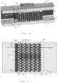
- Figure 2 shows a further embodiment according to the invention. Shown is in a bird's eye view the base piece 2 and a cross section of the middle piece 4.
- the difference between the total number of channels C dtotal ( ⁇ Cn @ 5d n ) at a given pipe row say 5d n and the total number of channels at the same pipe row C utotal ( ⁇ Cn @ 5u n+1 ) is one.
- the difference between the total number of channels C dtotal ( ⁇ Cn @ 5d n ) at a given pipe row say 5d n and the total number of channels of the neighbouring pipe row C utotal ( ⁇ Cn @ 5u n ) is one as well.
- the invention also works with equal number of channels.
- cavities 6a, 6b ... 6n are provided which connect subsequent pipe rows 5u1, 5d2 for redirection of each channel C1...Cn from “upwards” to “downwards”.
- the flow of coolant impinging on the enclosing surface 2s is turned round each time and for each channel C1 ...Cn.
- the holes are offset in direction S. Said otherwise, only each second pipes row 5d1 ...5dN is positioned equally in direction S. Coolant flowing for example into chamber 6a by a pipe of row 5u1 is distributed into the next two nearest pipes of the subsequent row 5d2 (indicated in the figure by continuous arrows Fc). This is equally effected at the base side (indicated in the figure by dashed arrows Fb), i.e. that same effect is observed on the base side.
- a pipe of for example row 5u1 is not part of only one channel (for example C1), but of two channels (C1 and C2). Due to the offset arrangement of pipe rows 5d1...5uN, each channel C1...Cn is allocated to more than one pipe of each row 5d1...5uN. Therefore, the flow F of a coolant liquid is not only alternating “up” and “down” as described with respect to figures 1a-1c , but in addition alternates (in a far more limited way) in "left” and "right” direction.
- This pipe or channel arrangement enables a low-turbulent flow F that allows for a high heat transfer at low pressure-drop which enhances heat absorption or release of the coolant.
Description
- The present invention relates to a cooler body which in particular is adapted for cooling electronic structural units or assemblies.
- As is known, the power dissipation and hence the heat evolution of electronic assemblies are increasing with the power-related further development of the electronic structural elements. It is true that these components are becoming smaller but their efficiency and hence the heat to be removed are increasing. Furthermore, due to their compactness, these electronic elements are positioned in a smaller space so that once again a higher local heat development results. The power dissipations achieved would be possible only with complicated and bulky cooling bodies when employing fan cooling and are therefore unacceptable. In case of large losses, air cooling therefore clearly reaches its limits.
- The new high-performance processors deliver about 70 to 100 W over an area of about 10 cm2 and thus achieve a far higher heat flux density. The processor manufacturers predict that a further increase in the waste heat is to be expected in the years ahead. In view of this development, those skilled in the art are considering liquid cooling for such applications. Liquid cooling more effectively dissipates the heat from the electronic assemblies, with the result that a higher power density is possible. Liquid coolers also allow more compact switch cabinets with numerous electronic components and operate very quietly.
- An exemplary generic cooling apparatus is disclosed in
EP 2 291 859 A1 , in which an insert is provided inside a cooling channel, the insert having a plurality of pins forming channels towards a cooler wall and being supplied with coolant via openings in an inclined surface of the inlet which is hit by a coolant flow from the coolant channel. - Specifically in the field of power electronics in automotive applications, more specific for inverter, converter and charger devices for electric vehicles, there is a need for an intense cooling of the electronic components, especially of the switching components like IGBT's or MOSFET's (since these are the components with the highest amount of power loss in such devices and therefore are the main heat sources within these).
US 2017/0092565 A1 discloses a micro heat transfer array for cooling of semiconductor devices, the array may comprise microjets, microchannels, fins or integrated microjets and fins. - To realize an effective cooling at an affordable price is difficult because due to physical restrictions liquids like water have to be used as a heat sink in combination with flow channels which provide large exchanging surfaces and produce high heat transfer coefficients. Further construction materials have to be used which provide a high thermal conductivity.
- A further demanding requirement is that there has to be direct contact between the electronic component and the cooling system (under avoidance of any air gaps to ensure sufficient heat conductivity) while simultaneously ensuring sufficient electrical insulation and avoiding mechanical stresses acting on the electronic component (e.g. due to vibration or thermal expansion).
- Further requirements especially for automotive solutions are that the cooling liquid has to transfer the received heat to the ambient air (via the vehicles radiator) which (in the worst case scenario for which the system has to be designed) can reach high temperatures (e.g. Dubai summer conditions). This leads to higher temperature levels of the cooling liquid compared to non-automotive applications and therefore to higher needed liquid flow rates. Therefore, such cooling systems have an increased need for a low pressure drop design to avoid to high pressure drops due to higher flow velocities.
- Due to increased security and maintenance demands (compared to stationary installations) an automotive cooling solution has an increased need for debris insensitivity. In addition, an automotive cooling system solution has to be designed appropriate to series production.
- The invention provides an improved cooler body, which, while being as compact as possible, permits a more effective cooling structure and a simpler design.
- A further object of the invention is to provide a cooler body, meeting the demands of cooling of electronic components in the automotive sector as described above.
- The invention relates to a cooler body, preferably designed for cooling of an electronic element, comprising a contact piece which comprises a contact surface for (thermal) contact to the part to be cooled and a base piece spaced apart from the contact piece by a middle piece in between the contact piece and the base piece. The middle piece comprises separate or individual holes forming multiple rows of parallelly arranged coolant pipes, whereby each pipe extends substantially from the contact piece to the base piece. At least two coolant channels - the channels enabling a flow of coolant (preferably water is to be used as coolant) from a coolant inlet to a coolant outlet- are formed by a sequence of parallel pipes connected by an enclosing surface of the contact piece and an enclosing surface of the base piece in such a way that each of the coolant channels run multiple times from the contact piece to the base piece and vice versa.
- Preferably, the cooler body comprises five or more of such coolant channels, for example a number of five to ten coolant channels. As another preferred option, the enclosing surface of the contact piece and the base piece each comprise multiple protrusions arranged successively and spaced apart from another on each enclosing surface, two successive protrusions together with part of the respective enclosing surface (and an end face of the middle piece) forming a cavity or chamber, the cavity connecting a pipe with the subsequent pipe. For example, essentially an enveloping piece (base piece or contact piece) provides chambers between itself and the middle piece by limiting protrusions whereby two neighbors of the parallel pipes lead into each chamber, thus enabling an inflow and a reverse outflow. Preferably, the protrusions are embodied as fin-like structures. Such fin-like structures can be have a straight form, or a waved form or a zig-zag-form and are preferably arranged transverse to an extension direction of the base / contact piece.
- Preferably, subsequent pipe rows are offset to each other (with respect to a general or overall flow direction of each channel).
- In embodiments with cavities as described above, optionally each cavity connects the exits of all pipes of a row with all entries of the pipes of the subsequent row.
- Preferably, the body is made from ceramic, preferably electrically insulating and thermally well conductive ceramic such as aluminium oxide or aluminium nitride. Alternatively, the body is made from metal such as aluminium or copper.
- In case of a ceramic body, the body optionally is a monolithic one, preferably manufactured by sintering green ceramic parts (raw material) of the base, middle and contact piece together in one step. Thus, additional assembly steps and thermal interfaces can be avoided.
- As an option, the base piece and the contact piece are embodied as parallel plates, whereby preferably an extension direction of the plates defines a general or overall direction of the channels. As another option, the base piece also serves as a contact piece for contacting the part to be cooled.
- As another option, the enclosing surface of the contact piece and the enclosing surface of the base piece are facing each other and/or the pipes are arranged at least roughly perpendicular to the enclosing surfaces.
- In some embodiments, the base piece and the contact piece comprise stabilizing ribs and/or the contact surface is designed for direct attachment to the part to be cooled.
- The invention also relates to a cooler, in particular electronic element cooler, specifically automotive power electronic cooler, comprising a cooler body according to the invention.
- The invention also relates to use of a cooler body according to the invention in a power electronics system, in particular in an automotive power electronics system.
- By way of example only, preferred embodiments of the invention will be described more fully hereinafter with reference to the accompanying figures, wherein:
-
Figures 1a to 1c show a first embodiment of a cooler body according to the invention; -
Figure 2 shows a further embodiment of parts of a cooler body. -
Figure 1a-1c show a first embodiment of a cooler body 1 according to the invention, together with apart 100 to be cooled, e.g. a power electronic element such as a MOS-FET or IGBT, in particular as part of an automotive electronic circuit. As shown infigure 1a in a 3D-view, the cooler body 1 comprises three main parts, acontact piece 2, amiddle piece 4 and abase piece 3. Theelectronic component 100 to be cooled is preferably directly contacted by thecontact piece 2, e.g. by a thermal adhesive, a thermal grease or some other interface material with high thermal conductivity. - The body 1 can be made from metal such as aluminum or copper, whereby the three
pieces individual parts parts base piece 3 and thecontact piece 2 are manufactured from two layers of "green" ceramic instead of one. This would simplify the forming process of the unsintered ceramic. In this case preferably some additional ribs are added to stabilize the structure. (The body 1, alternatively, can be metallic and insulations are added for cooling the electronic components.) - The
contact piece 2 and thebase piece 3 are spaced apart by themiddle piece 4 in between. In the example, thecontact piece 2 and thebase piece 3 embodied as long plates, arranged parallel to each other and extending in a direction S. - The
middle piece 4 is in the example embodied as a block, shorter than theplates middle piece 4 is perforated, theholes middle piece 4 comprises a multitude ofpipes pipes surface 2s of thecontact piece 2 to the facingsurface 3s of thebase piece 3, thereby at least roughly perpendicular to thesurface 2s andsurface 3s or the angle between the extension direction H of eachhole plates - The three
pieces surfaces surfaces pipes figure 1a but angled or formed like a "U". As an option, thebase piece 4 is also embodied as a contact piece for thermal contact to the part to be cooled. - The
surfaces pipes middle piece 4 andbase piece 3 as well as betweenmiddle piece 4 andcontact piece 2; or more precisely, there is a gap G between each end ofpipes surface - Each gap G is established by
protrusions surface 2s, 3s. Said otherwise, there areprotrusions inner side contact plate 2 andbase plate 3 which serve as distance holders to thepipe piece 4 in the middle. The gaps G allow for coolant to enter or exit in thepipes outer pieces inner piece 4. - According to the invention, the
protrusions - For better view of such fin-like protrusions,
figure 1b shows only thebase plate 3s with fin-like structures 3p on the enclosingsurface 3s. The fin-like structures 3p are arranged perpendicular to the extension direction S or the angle β between the extension direction P of eachfin 3p and the extension direction S is a right angle or at least roughly 90°. - In the example, the
fins 3p are embodied as straight fins. Alternatively, they are wave-like or zig-zag formed. The height of theprotrusions 3p define the gap G between enclosingsurface 3s and the pipes of the middle piece. - The
fins 3p are arranged successively and spaced (equally) apart from each other on the enclosingsurface 3s. The distance D between twosuccessive protrusions 3p of arespective piece contact piece 2 is designed accordingly, however with an offset of (roughly) one pipe (diameter) with respect to thebase piece 3, which is explained in more detail below. - Referring again to
figure 1a , it can be seen that thus, twosuccessive protrusions respective enclosing surface cavity 6, with the end 7 of onepipe 5d as a first opening and theend 8 of the followingpipe 5u as a second opening. In other words, thecavity 6 connects (the end 7 of) onepipe 5u with (theend 8 of) thesubsequent pipe 5d. - According to the invention, the enclosing
surfaces cavities 6 connect thepipes first pipe 5d, running multiple times from thecontact piece 2 to thebase piece 3 and vice versa through thepipes cavities 6 in between thepipes figures 1a-1c , theprotrusions 2p and hence the "upper"cavities 6 at thecontact piece 2 are at least one pipe (diameter) offset -preferably offset more than one pipe diameter-with respect to theprotrusions 3p and hence the "below"cavities 6 at thebase piece 3 in extension direction S to achieve this result of directionally alternating channels. Such an alternating channel C is in more detail illustrated infigure 1c . -
Figure 1c illustrates schematically in a 3D-view such an alternating coolant channel C according to the invention, indicated by the bright arrows inside the cooler body 1 (for ease of illustration, only one of the two or more channels is explicitly depicted). A coolant (not shown) enters the cooler body 1 respectively a channel C at an inlet IN (in the figure at the left side) in direction of the extension direction S of the cooler body 1. The coolant is first directed at the inner or enclosingsurface 2s of the contact piece 2 (indicated by the first two left arrows), where the coolant takes heat from thecontact piece 2 respectively theelectronics 100. - Then due to a
first protrusion 2p of the enclosingsurface 2s of thecontact piece 2, the channel C runs the first time "down" from thecontact piece 2 to thebase piece 3 through afirst pipe 5d (indicated by the first dashed arrow from the left). - Then, there is a first
base piece cavity 6, formed by the enclosingsurface 3s with twosuccessive protrusions 3p of thebase piece 3, the cavity connecting the end of saidfirst pipe 5d with an end of thepipe 5u following in direction S. Said otherwise, the exit of thefirst pipe 5d flows intocavity 6 and the base-side opening of thesecond pipe 5u is exit ofcavity 6. The channel C thus is redirected about 180° or in other words makes a U-turn (indicated by the first bent arrow). Thus, the coolant exiting from thefirst pipe 5d forms an impinging flow on the enclosingsurface 2s and enters thesecond pipe 5u. - The channel C then runs back or "up" to the
contact piece 2 according to thesecond pipe 5u ((indicated by the upwards continuous arrow). The "upwards"pipe 5u leads intocontact piece cavity 6 atcontact piece 2. Here, the coolant again can take up heat fromcontact piece 2 respectivelyelectronics 100. - There again, the channel C is redirected about 180° due to
cavity 6, leading into a second "downwards" pipe. Said otherwise, the coolant now sinks second time from thecontact piece 2 to thebase piece 3 through the next pipe of holeymiddle piece 4. As can be seen, the fin-like structures outer parts - This "down- and upwards" course from the
contact piece 2 to thebase piece 3 of channels C is repeated several times (in the example five times). Hence, the structure of the coolant body 1 as suggest provides in a simple and compact way channels C or coolant flow which alternates multiple times between thecontact piece 2 and thebase piece 3 between inlet IN and outlet OUT of the cooler body 1. The design enables an impact or impingement coolant flow on the contact piece 2 (and base piece 3) and a relatively large contact area between coolant andcontact piece 2 resp.surface 2s/3s for heat transfer. -
Figure 2 shows a further embodiment according to the invention. Shown is in a bird's eye view thebase piece 2 and a cross section of themiddle piece 4. - In this embodiment, several parallel channels C1, C2,...Cn with alternating direction between
contact piece 2 andbase piece 3 as described above are present, provided by rows 5d1, 5u1, 5d2, 5u2, ... 5dN of holes in themiddle piece 4. The rows of pipes 5d1, 5u1, 5d2, 5u2, ... 5uN are separated in extension direction (or general direction of the coolant flow F) bybase side protrusions 2p, extending along the whole wide of themiddle piece 4 in direction P orthogonal to direction S (likewise, but one pipe offset separation is effected by such base side protrusions, not shown infigure 2 ). - Preferably, the difference between the total number of channels Cdtotal (ΣCn @ 5dn) at a given pipe row say 5dn and the total number of channels at the same pipe row Cutotal (ΣCn @ 5un+1) is one. The difference between the total number of channels Cdtotal (ΣCn @ 5dn) at a given pipe row say 5dn and the total number of channels of the neighbouring pipe row Cutotal (ΣCn @ 5un) is one as well. However, the invention also works with equal number of channels.
- By the
protrusions 2p,cavities 6a, 6b ... 6n are provided which connect subsequent pipe rows 5u1, 5d2 for redirection of each channel C1...Cn from "upwards" to "downwards". The flow of coolant impinging on the enclosingsurface 2s is turned round each time and for each channel C1 ...Cn. - In the exemplary embodiment, the holes are offset in direction S. Said otherwise, only each second pipes row 5d1 ...5dN is positioned equally in direction S. Coolant flowing for example into chamber 6a by a pipe of row 5u1 is distributed into the next two nearest pipes of the subsequent row 5d2 (indicated in the figure by continuous arrows Fc). This is equally effected at the base side (indicated in the figure by dashed arrows Fb), i.e. that same effect is observed on the base side.
- Thus, a pipe of for example row 5u1 is not part of only one channel (for example C1), but of two channels (C1 and C2). Due to the offset arrangement of pipe rows 5d1...5uN, each channel C1...Cn is allocated to more than one pipe of each row 5d1...5uN. Therefore, the flow F of a coolant liquid is not only alternating "up" and "down" as described with respect to
figures 1a-1c , but in addition alternates (in a far more limited way) in "left" and "right" direction. This pipe or channel arrangement enables a low-turbulent flow F that allows for a high heat transfer at low pressure-drop which enhances heat absorption or release of the coolant.
Claims (15)
- A cooler body (1), in particular designed for cooling of an electronic element (100), comprisingo a contact piece (2), comprising a contact surface for contact to the part to be cooled (100),o a base piece (3) spaced apart from the contact piece (2) byo a middle piece (4) in between the contact piece (2) and the base piece (3),wherebyo the middle piece (4) comprises separate holes forming multiple rows of parallelly arranged coolant pipes (5d, 5u, 5d1, 5u1, 5d2, 5u2-5dN),o each pipe extends substantially from the contact piece (2) to the base piece (3) ando at least two, in particular at least five, parallel coolant channels (C, C1-Cn) are formed by sequences of parallel pipes (5d, 5u) connected by an enclosing surface (2s) of the contact piece (2) and an enclosing surface (3s) of the base piece (3) in such a way that the at least two coolant channels (C, C1-Cn) each run multiple times from the contact piece (2) to the base piece (3) and vice versa.
- The cooler body (1) according to claim 1,
characterized in that
the enclosing surface (2s) of the contact piece (2) and the enclosing surface (3s) the base piece (3) each comprise multiple protrusions (2p, 3p) arranged successively and spaced apart from another on each enclosing surface (2s, 3s), two successive protrusions (2p, 3p) together with part of the respective enclosing surface (2s, 3s) forming a cavity (6, 6a, 6b), the cavity (6, 6a, 6b) connecting a pipe (5d, 5u) with the subsequent pipe (5u, 5d). - The cooler body (1) according to claim 2,
characterized in that
the protrusions (2p, 3p) are, in particular straight, waved and/or zig-zag, fin-like structures. - The cooler body (1) according to any of the preceding claims,
characterized in that
the base piece (3) is designed as a further contact surface for contact to the part to be cooled. - The cooler body (1) according to claim 2,
characterized in that
each cavity (6a, 6b) connects the exits of all pipes of a row (5u1, 5d2, 5u2-5dN) with all entries of the pipes of the subsequent row (5d2, 5u2-5dN). - The cooler body (1) according to any of the preceding claims,
characterized in that
subsequent pipe rows (5d1, 5u1, 5d2, 5u2-5dN) are offset to each other. - The cooler body (1) according to any of the preceding claims,
characterized in that
the body (1) is made from ceramic, in particular aluminium oxide or aluminium nitride - The cooler body (1) according to claim 7,
characterized in that
the body (1) is a monolithic body, in particular formed by sintering green ceramic parts of the base piece, the middle piece and the contact piece together in one step. - The cooler body (1) according to any of the preceding claims,
characterized in that
the body (1) is made from metal, in particular aluminium or copper. - The cooler body (1) according to any of the preceding claims,
characterized in that
the base piece (3) and the contact piece (2) are embodied as parallel plates, in particular wherein an extension direction (S) of the plates defines a general direction of the channels (C, C1-Cn). - The cooler body (1) according to any of the preceding claims,
characterized in thato the enclosing surface (2s) of the contact piece (2) and the enclosing surface (3s) of the base piece (3) are facing each other and/oro the pipes (5d, 5u) are arranged at least roughly perpendicular to the enclosing surfaces (2s, 3s). - The cooler body (1) according to any of the preceding claims,
characterized in that
the base piece (3) and the contact piece (2) comprise stabilizing ribs. - The cooler body (1) according to any of the preceding claims,
characterized in that
the contact surface of the contact piece (2) is designed for direct attachment to the part to be cooled. - Cooler, in particular electronic element cooler, specifically automotive power electronic cooler, comprising a cooler body (1) according to claim 1.
- Use of a cooler body (1) according to claim 1 in a power electronics system, in particular in an automotive power electronics system.
Priority Applications (4)
| Application Number | Priority Date | Filing Date | Title |
|---|---|---|---|
| ES19189229T ES2964171T3 (en) | 2019-07-30 | 2019-07-30 | Cooler body |
| EP19189229.8A EP3772096B1 (en) | 2019-07-30 | 2019-07-30 | Cooler body |
| US16/937,387 US11644253B2 (en) | 2019-07-30 | 2020-07-23 | Cooler and cooler body |
| CN202010733899.3A CN112310014A (en) | 2019-07-30 | 2020-07-24 | Cooler main body |
Applications Claiming Priority (1)
| Application Number | Priority Date | Filing Date | Title |
|---|---|---|---|
| EP19189229.8A EP3772096B1 (en) | 2019-07-30 | 2019-07-30 | Cooler body |
Publications (2)
| Publication Number | Publication Date |
|---|---|
| EP3772096A1 EP3772096A1 (en) | 2021-02-03 |
| EP3772096B1 true EP3772096B1 (en) | 2023-08-30 |
Family
ID=67544007
Family Applications (1)
| Application Number | Title | Priority Date | Filing Date |
|---|---|---|---|
| EP19189229.8A Active EP3772096B1 (en) | 2019-07-30 | 2019-07-30 | Cooler body |
Country Status (3)
| Country | Link |
|---|---|
| EP (1) | EP3772096B1 (en) |
| CN (1) | CN112310014A (en) |
| ES (1) | ES2964171T3 (en) |
Family Cites Families (2)
| Publication number | Priority date | Publication date | Assignee | Title |
|---|---|---|---|---|
| KR101446828B1 (en) | 2008-06-18 | 2014-10-30 | 브루사 일렉트로닉 아게 | Cooling system, in particular for electronic structural units |
| US9953899B2 (en) * | 2015-09-30 | 2018-04-24 | Microfabrica Inc. | Micro heat transfer arrays, micro cold plates, and thermal management systems for cooling semiconductor devices, and methods for using and making such arrays, plates, and systems |
-
2019
- 2019-07-30 ES ES19189229T patent/ES2964171T3/en active Active
- 2019-07-30 EP EP19189229.8A patent/EP3772096B1/en active Active
-
2020
- 2020-07-24 CN CN202010733899.3A patent/CN112310014A/en active Pending
Also Published As
| Publication number | Publication date |
|---|---|
| CN112310014A (en) | 2021-02-02 |
| ES2964171T3 (en) | 2024-04-04 |
| EP3772096A1 (en) | 2021-02-03 |
Similar Documents
| Publication | Publication Date | Title |
|---|---|---|
| US8472193B2 (en) | Semiconductor device | |
| EP3174093B1 (en) | Cooled power electronic assembly | |
| US8441794B2 (en) | Liquid cooler and method of its manufacture | |
| US8528628B2 (en) | Carbon-based apparatus for cooling of electronic devices | |
| US8391008B2 (en) | Power electronics modules and power electronics module assemblies | |
| JP5135225B2 (en) | Use of a micro heat transfer device as a fluid cooler for micro heat transfer and electronic devices | |
| EP1790935A2 (en) | Fow distributing element for a cooling plate | |
| JP6094687B2 (en) | Semiconductor module and electrically driven vehicle | |
| JP2016119450A (en) | Thermoelectric conversion device and application system thereof | |
| CN107084550A (en) | Semiconductor refrigerating component and ice cream maker | |
| JP2009277699A (en) | Heat sink, heat sink assembly, semiconductor module, and semiconductor device with cooling device | |
| EP3772096B1 (en) | Cooler body | |
| CN113543575A (en) | Radiator and communication equipment | |
| US11644253B2 (en) | Cooler and cooler body | |
| JP2008235572A (en) | Electronic component cooling device | |
| RU2803414C1 (en) | Radiator with efficient and distributed heat removal | |
| RU2809232C1 (en) | Radiator with groups of thin fins | |
| WO2021027454A1 (en) | Heat dissipation device, and base station | |
| JP2005123260A (en) | Water-cooled heatsink | |
| JP2008159757A (en) | Cooling structure of heat generating substance, and manufacturing method of same cooling structure | |
| WO2020031753A1 (en) | Cooler and semiconductor module | |
| CN117156662A (en) | Metal substrate, preparation method and heat dissipation circuit board | |
| JP2006060114A (en) | Cooling device |
Legal Events
| Date | Code | Title | Description |
|---|---|---|---|
| PUAI | Public reference made under article 153(3) epc to a published international application that has entered the european phase |
Free format text: ORIGINAL CODE: 0009012 |
|
| STAA | Information on the status of an ep patent application or granted ep patent |
Free format text: STATUS: THE APPLICATION HAS BEEN PUBLISHED |
|
| AK | Designated contracting states |
Kind code of ref document: A1 Designated state(s): AL AT BE BG CH CY CZ DE DK EE ES FI FR GB GR HR HU IE IS IT LI LT LU LV MC MK MT NL NO PL PT RO RS SE SI SK SM TR |
|
| AX | Request for extension of the european patent |
Extension state: BA ME |
|
| STAA | Information on the status of an ep patent application or granted ep patent |
Free format text: STATUS: REQUEST FOR EXAMINATION WAS MADE |
|
| 17P | Request for examination filed |
Effective date: 20210723 |
|
| RBV | Designated contracting states (corrected) |
Designated state(s): AL AT BE BG CH CY CZ DE DK EE ES FI FR GB GR HR HU IE IS IT LI LT LU LV MC MK MT NL NO PL PT RO RS SE SI SK SM TR |
|
| GRAP | Despatch of communication of intention to grant a patent |
Free format text: ORIGINAL CODE: EPIDOSNIGR1 |
|
| STAA | Information on the status of an ep patent application or granted ep patent |
Free format text: STATUS: GRANT OF PATENT IS INTENDED |
|
| INTG | Intention to grant announced |
Effective date: 20230316 |
|
| GRAS | Grant fee paid |
Free format text: ORIGINAL CODE: EPIDOSNIGR3 |
|
| GRAA | (expected) grant |
Free format text: ORIGINAL CODE: 0009210 |
|
| STAA | Information on the status of an ep patent application or granted ep patent |
Free format text: STATUS: THE PATENT HAS BEEN GRANTED |
|
| AK | Designated contracting states |
Kind code of ref document: B1 Designated state(s): AL AT BE BG CH CY CZ DE DK EE ES FI FR GB GR HR HU IE IS IT LI LT LU LV MC MK MT NL NO PL PT RO RS SE SI SK SM TR |
|
| REG | Reference to a national code |
Ref country code: GB Ref legal event code: FG4D |
|
| REG | Reference to a national code |
Ref country code: CH Ref legal event code: EP |
|
| REG | Reference to a national code |
Ref country code: DE Ref legal event code: R096 Ref document number: 602019035995 Country of ref document: DE |
|
| REG | Reference to a national code |
Ref country code: IE Ref legal event code: FG4D |
|
| REG | Reference to a national code |
Ref country code: LT Ref legal event code: MG9D |
|
| REG | Reference to a national code |
Ref country code: NL Ref legal event code: MP Effective date: 20230830 |
|
| REG | Reference to a national code |
Ref country code: AT Ref legal event code: MK05 Ref document number: 1606549 Country of ref document: AT Kind code of ref document: T Effective date: 20230830 |
|
| PG25 | Lapsed in a contracting state [announced via postgrant information from national office to epo] |
Ref country code: GR Free format text: LAPSE BECAUSE OF FAILURE TO SUBMIT A TRANSLATION OF THE DESCRIPTION OR TO PAY THE FEE WITHIN THE PRESCRIBED TIME-LIMIT Effective date: 20231201 |
|
| PG25 | Lapsed in a contracting state [announced via postgrant information from national office to epo] |
Ref country code: IS Free format text: LAPSE BECAUSE OF FAILURE TO SUBMIT A TRANSLATION OF THE DESCRIPTION OR TO PAY THE FEE WITHIN THE PRESCRIBED TIME-LIMIT Effective date: 20231230 |
|
| PG25 | Lapsed in a contracting state [announced via postgrant information from national office to epo] |
Ref country code: SE Free format text: LAPSE BECAUSE OF FAILURE TO SUBMIT A TRANSLATION OF THE DESCRIPTION OR TO PAY THE FEE WITHIN THE PRESCRIBED TIME-LIMIT Effective date: 20230830 Ref country code: RS Free format text: LAPSE BECAUSE OF FAILURE TO SUBMIT A TRANSLATION OF THE DESCRIPTION OR TO PAY THE FEE WITHIN THE PRESCRIBED TIME-LIMIT Effective date: 20230830 Ref country code: NO Free format text: LAPSE BECAUSE OF FAILURE TO SUBMIT A TRANSLATION OF THE DESCRIPTION OR TO PAY THE FEE WITHIN THE PRESCRIBED TIME-LIMIT Effective date: 20231130 Ref country code: LV Free format text: LAPSE BECAUSE OF FAILURE TO SUBMIT A TRANSLATION OF THE DESCRIPTION OR TO PAY THE FEE WITHIN THE PRESCRIBED TIME-LIMIT Effective date: 20230830 Ref country code: LT Free format text: LAPSE BECAUSE OF FAILURE TO SUBMIT A TRANSLATION OF THE DESCRIPTION OR TO PAY THE FEE WITHIN THE PRESCRIBED TIME-LIMIT Effective date: 20230830 Ref country code: IS Free format text: LAPSE BECAUSE OF FAILURE TO SUBMIT A TRANSLATION OF THE DESCRIPTION OR TO PAY THE FEE WITHIN THE PRESCRIBED TIME-LIMIT Effective date: 20231230 Ref country code: HR Free format text: LAPSE BECAUSE OF FAILURE TO SUBMIT A TRANSLATION OF THE DESCRIPTION OR TO PAY THE FEE WITHIN THE PRESCRIBED TIME-LIMIT Effective date: 20230830 Ref country code: GR Free format text: LAPSE BECAUSE OF FAILURE TO SUBMIT A TRANSLATION OF THE DESCRIPTION OR TO PAY THE FEE WITHIN THE PRESCRIBED TIME-LIMIT Effective date: 20231201 Ref country code: FI Free format text: LAPSE BECAUSE OF FAILURE TO SUBMIT A TRANSLATION OF THE DESCRIPTION OR TO PAY THE FEE WITHIN THE PRESCRIBED TIME-LIMIT Effective date: 20230830 Ref country code: AT Free format text: LAPSE BECAUSE OF FAILURE TO SUBMIT A TRANSLATION OF THE DESCRIPTION OR TO PAY THE FEE WITHIN THE PRESCRIBED TIME-LIMIT Effective date: 20230830 |
|
| PG25 | Lapsed in a contracting state [announced via postgrant information from national office to epo] |
Ref country code: PL Free format text: LAPSE BECAUSE OF FAILURE TO SUBMIT A TRANSLATION OF THE DESCRIPTION OR TO PAY THE FEE WITHIN THE PRESCRIBED TIME-LIMIT Effective date: 20230830 Ref country code: NL Free format text: LAPSE BECAUSE OF FAILURE TO SUBMIT A TRANSLATION OF THE DESCRIPTION OR TO PAY THE FEE WITHIN THE PRESCRIBED TIME-LIMIT Effective date: 20230830 |
|
| REG | Reference to a national code |
Ref country code: ES Ref legal event code: FG2A Ref document number: 2964171 Country of ref document: ES Kind code of ref document: T3 Effective date: 20240404 |