EP3771920B1 - Radarantennenanordnung mit panoramischer erkennung - Google Patents
Radarantennenanordnung mit panoramischer erkennung Download PDFInfo
- Publication number
- EP3771920B1 EP3771920B1 EP20197236.1A EP20197236A EP3771920B1 EP 3771920 B1 EP3771920 B1 EP 3771920B1 EP 20197236 A EP20197236 A EP 20197236A EP 3771920 B1 EP3771920 B1 EP 3771920B1
- Authority
- EP
- European Patent Office
- Prior art keywords
- lateral
- directive
- antenna assembly
- radar antenna
- slot
- Prior art date
- Legal status (The legal status is an assumption and is not a legal conclusion. Google has not performed a legal analysis and makes no representation as to the accuracy of the status listed.)
- Active
Links
Images


Classifications
-
- G—PHYSICS
- G01—MEASURING; TESTING
- G01S—RADIO DIRECTION-FINDING; RADIO NAVIGATION; DETERMINING DISTANCE OR VELOCITY BY USE OF RADIO WAVES; LOCATING OR PRESENCE-DETECTING BY USE OF THE REFLECTION OR RERADIATION OF RADIO WAVES; ANALOGOUS ARRANGEMENTS USING OTHER WAVES
- G01S13/00—Systems using the reflection or reradiation of radio waves, e.g. radar systems; Analogous systems using reflection or reradiation of waves whose nature or wavelength is irrelevant or unspecified
- G01S13/02—Systems using reflection of radio waves, e.g. primary radar systems; Analogous systems
- G01S13/04—Systems determining presence of a target
-
- G—PHYSICS
- G01—MEASURING; TESTING
- G01S—RADIO DIRECTION-FINDING; RADIO NAVIGATION; DETERMINING DISTANCE OR VELOCITY BY USE OF RADIO WAVES; LOCATING OR PRESENCE-DETECTING BY USE OF THE REFLECTION OR RERADIATION OF RADIO WAVES; ANALOGOUS ARRANGEMENTS USING OTHER WAVES
- G01S13/00—Systems using the reflection or reradiation of radio waves, e.g. radar systems; Analogous systems using reflection or reradiation of waves whose nature or wavelength is irrelevant or unspecified
- G01S13/88—Radar or analogous systems specially adapted for specific applications
- G01S13/93—Radar or analogous systems specially adapted for specific applications for anti-collision purposes
- G01S13/931—Radar or analogous systems specially adapted for specific applications for anti-collision purposes of land vehicles
-
- G—PHYSICS
- G01—MEASURING; TESTING
- G01S—RADIO DIRECTION-FINDING; RADIO NAVIGATION; DETERMINING DISTANCE OR VELOCITY BY USE OF RADIO WAVES; LOCATING OR PRESENCE-DETECTING BY USE OF THE REFLECTION OR RERADIATION OF RADIO WAVES; ANALOGOUS ARRANGEMENTS USING OTHER WAVES
- G01S7/00—Details of systems according to groups G01S13/00, G01S15/00, G01S17/00
- G01S7/02—Details of systems according to groups G01S13/00, G01S15/00, G01S17/00 of systems according to group G01S13/00
- G01S7/03—Details of HF subsystems specially adapted therefor, e.g. common to transmitter and receiver
-
- H—ELECTRICITY
- H01—ELECTRIC ELEMENTS
- H01Q—ANTENNAS, i.e. RADIO AERIALS
- H01Q1/00—Details of, or arrangements associated with, antennas
- H01Q1/27—Adaptation for use in or on movable bodies
- H01Q1/32—Adaptation for use in or on road or rail vehicles
- H01Q1/3208—Adaptation for use in or on road or rail vehicles characterised by the application wherein the antenna is used
- H01Q1/3233—Adaptation for use in or on road or rail vehicles characterised by the application wherein the antenna is used particular used as part of a sensor or in a security system, e.g. for automotive radar, navigation systems
-
- H—ELECTRICITY
- H01—ELECTRIC ELEMENTS
- H01Q—ANTENNAS, i.e. RADIO AERIALS
- H01Q1/00—Details of, or arrangements associated with, antennas
- H01Q1/27—Adaptation for use in or on movable bodies
- H01Q1/32—Adaptation for use in or on road or rail vehicles
- H01Q1/325—Adaptation for use in or on road or rail vehicles characterised by the location of the antenna on the vehicle
- H01Q1/3275—Adaptation for use in or on road or rail vehicles characterised by the location of the antenna on the vehicle mounted on a horizontal surface of the vehicle, e.g. on roof, hood, trunk
-
- H—ELECTRICITY
- H01—ELECTRIC ELEMENTS
- H01Q—ANTENNAS, i.e. RADIO AERIALS
- H01Q21/00—Antenna arrays or systems
-
- H—ELECTRICITY
- H01—ELECTRIC ELEMENTS
- H01Q—ANTENNAS, i.e. RADIO AERIALS
- H01Q21/00—Antenna arrays or systems
- H01Q21/0006—Particular feeding systems
- H01Q21/0037—Particular feeding systems linear waveguide fed arrays
- H01Q21/0043—Slotted waveguides
- H01Q21/005—Slotted waveguides arrays
-
- H—ELECTRICITY
- H01—ELECTRIC ELEMENTS
- H01Q—ANTENNAS, i.e. RADIO AERIALS
- H01Q25/00—Antennas or antenna systems providing at least two radiating patterns
-
- B—PERFORMING OPERATIONS; TRANSPORTING
- B60—VEHICLES IN GENERAL
- B60R—VEHICLES, VEHICLE FITTINGS, OR VEHICLE PARTS, NOT OTHERWISE PROVIDED FOR
- B60R11/00—Arrangements for holding or mounting articles, not otherwise provided for
- B60R2011/0001—Arrangements for holding or mounting articles, not otherwise provided for characterised by position
- B60R2011/004—Arrangements for holding or mounting articles, not otherwise provided for characterised by position outside the vehicle
-
- G—PHYSICS
- G01—MEASURING; TESTING
- G01S—RADIO DIRECTION-FINDING; RADIO NAVIGATION; DETERMINING DISTANCE OR VELOCITY BY USE OF RADIO WAVES; LOCATING OR PRESENCE-DETECTING BY USE OF THE REFLECTION OR RERADIATION OF RADIO WAVES; ANALOGOUS ARRANGEMENTS USING OTHER WAVES
- G01S13/00—Systems using the reflection or reradiation of radio waves, e.g. radar systems; Analogous systems using reflection or reradiation of waves whose nature or wavelength is irrelevant or unspecified
- G01S13/88—Radar or analogous systems specially adapted for specific applications
- G01S13/93—Radar or analogous systems specially adapted for specific applications for anti-collision purposes
- G01S13/931—Radar or analogous systems specially adapted for specific applications for anti-collision purposes of land vehicles
- G01S2013/9327—Sensor installation details
- G01S2013/93273—Sensor installation details on the top of the vehicles
-
- G—PHYSICS
- G01—MEASURING; TESTING
- G01S—RADIO DIRECTION-FINDING; RADIO NAVIGATION; DETERMINING DISTANCE OR VELOCITY BY USE OF RADIO WAVES; LOCATING OR PRESENCE-DETECTING BY USE OF THE REFLECTION OR RERADIATION OF RADIO WAVES; ANALOGOUS ARRANGEMENTS USING OTHER WAVES
- G01S7/00—Details of systems according to groups G01S13/00, G01S15/00, G01S17/00
- G01S7/02—Details of systems according to groups G01S13/00, G01S15/00, G01S17/00 of systems according to group G01S13/00
- G01S7/027—Constructional details of housings, e.g. form, type, material or ruggedness
- G01S7/028—Miniaturisation, e.g. surface mounted device [SMD] packaging or housings
Definitions
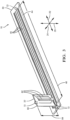
- an antenna assembly configured to provide a panoramic field of view, i.e. 360 degree coverage, from within a single, small footprint package mounted atop a vehicle, e.g. see Figs 1 and 2 .
- the antenna assembly consists of two antennas arrays within a the single housing instead of the six radar units distributed to different locations on the vehicle as is the case for prior attempts to provide panoramic coverage.
- the antenna assembly is housed in a relatively low profile, small footprint housing similar to a 'shark-fin' shaped antenna commonly used by vehicle entertainment systems for receiving satellite radio signals.
- the antenna assembly advantageously employs vertical polarization of radar signals so radar signals can bend around the edges of the vehicle such that objects can be detected when located below a line of sight from the antenna that is limited or determined by a roofline of the vehicle assembly.
- Fig. 2 further illustrates non-limiting details of the assembly 10, which may include a housing 20 with the shark-fin shape familiar to those in the satellite broadcast reception arts for vehicles.
- various figures define several axes so direction relative to the assembly 10 and the vehicle 12 can be readily understood.
- the axes include a longitudinal axis 22 is defined that substantially corresponds to a forward direction and a rearward direction relative to the vehicle 12, a lateral axis 24 is defined that substantially corresponds to a leftward direction and a rightward direction relative to the vehicle 12, and a vertical axis 26 is defined that substantially corresponds to an upward direction and a downward direction relative to the vehicle 12.
- the term 'substantially corresponds' is used to allow for difference between directions or axes aligned with or normal to the surface of the vehicle where the assembly 10 is mounted (e.g. the roof of the vehicle 12), and directions or axes aligned with or normal to the direction of gravity, generally normal to the surface of the Earth. That is, the various axes described herein may not be perfectly aligned with the Earth because of the slope roof of the vehicle 12 upon which the assembly 10 is mounted.
- Fig. 3 further illustrates non-limiting details of the assembly 10 with the housing 20 and other mechanical fixtures removed, as will be recognized by those in the art.
- the assembly 10 includes a horizontal array 30 and a vertical array 32.
- the horizontal array 30 is generally configured to preferentially detect objects in a forward area 34 ( Fig. 4 ) and a rearward area 36 relative to about the vehicle 12.
- the vertical array 32 is generally configured to preferentially detect objects in a leftward area 38 and a rightward area 40 relative to or about the vehicle 12.
- the horizontal array 30 and the vertical array 32 are also generally configured to cooperate with each other to detect an object in a panoramic area 42 that surrounds the vehicle 12.
- the varying distance from the vehicle 12 to the boundaries of the various areas (34, 36, 38, 40) are an indication of the relative range from the vehicle 12 or the assembly 10 that a particular test object is likely to be detected.
- the characterization of the field of view of the assembly 10 or the radar system 14 as being panoramic or covering 360° does not mean that the sensitivity is necessarily uniform in every direction, but rather that there is not direction where the sensitivity is substantially zero. That is, there is not a direction where an object relatively close to the vehicle 12 could 'hide' from the radar system 14.
- the horizontal array 30 includes or defines one or more antenna elements hereafter referred to individually as the directive element 46.
- Fig. 3 shows six of the directive element 46 arranged upon the horizontal substrate 44, and Figs. 5 and 6 show one of the six in more detail.
- a horizontal substrate suitable for the application described herein has a length of 122 millimeters (mm), a width of 40mm, and is formed of TLP-5 available from Taconic Advanced Dielectric Division with a thickness of 0.76mm.
- the directive element 46 is oriented such that a directive length 48 of the directive element 46 is measured in a direction substantially parallel to the longitudinal axis 22.
- a suitable value for the directive length 48 is 112mm.
- the phrase substantially parallel to the longitudinal axis is used to allow for a direction or angle that is not precisely aligned with a particular axis due to the roof angle proximate to where the assembly 10 is mounted onto the roof of the vehicle 12.
- the directive element 46 described herein may be characterized as a substrate integrated waveguide (SIW) slot array with a microstrip 70 electrically connected to a Monolithic Microwave Integrated Circuit (MMIC 72), and may also be referred to by some as an end-fire antenna.
- the MMIC 72 may include the aforementioned radar transceiver, and may be connected to the microstrip 70 by wire-bonding, as will be recognized by those in the art.
- electromagnetic energy is fed into an end of this type of antenna, radiation is directed along the length of the antenna creating a beam that propagates in that same direction.
- Such an antenna may be fed from the opposite end as illustrated to emit a beam in the opposite direction.
- a forward beam and a rearward beam can be generated simultaneously so forward and rearward detection can be performed simultaneously.
- the horizontal array 30 is configured to emit a vertically-polarized radar signal, it follows that the horizontal array 30 also preferentially detects a vertically-polarized reflected signal.
- the directive element 46 includes a plurality of directive slots 50 arrayed in a longitudinal direction substantially parallel to the longitudinal axis 22, where any deviation from the longitudinal axis is primarily due to the roof angle of the vehicle 12.
- a suitable number of slots for the directive element 46 would include seventy-three slots.
- Each of the plurality of directive slots 50 is characterized by a lateral length measured in a lateral direction parallel to the lateral axis 24.
- the plurality of directive slots 50 include a first lateral slot 52 located proximate to a first end 54 of the directive element 46, and the lateral length of the first lateral slot 52 is characterized by a first lateral value 56, for example 0.466mm.
- the plurality of directive slots 50 also include a middle lateral slot 60 located proximate to a mid-point 58 of the directive element 46 and the lateral length of the middle lateral slot 60 is characterized by a middle lateral value 62, for example 1.07mm.
- the plurality of directive slots 50 are configured so that the lateral lengths of the plurality of directive slots 50 vary progressively from the first lateral value 56 to the middle lateral value 62. As illustrated in this non-limiting example, the first lateral value 56 is less than the middle lateral value 62.
- the SIW width 74 is varied to be wider at the first end 54 and the second end 66, and gradually narrows down towards the midpoint 58 of the directive element 46.
- the advantage of varying the SIW width 74 and the lateral length of the plurality of directive slots 50 along the directive element 46 is that a 'taper' is formed whereby the side-lobe characteristic of the radar signal 16 emitted by the directive element 46 is improved.
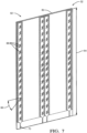
- Fig. 7 illustrates four of the fan element 82 on one side of the vertical array 32
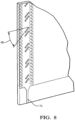
- Fig. 8 illustrates one of the fan element 82 in more detail.
- the vertical substrate 80 suitable for the application described herein has a length of 40mm, a width of 30mm, and is formed of R04835 available from Rogers Corporation with a thickness of 0.508mm.
- the fan element 82 in this non limiting example is also an SIW slot array type element similar to the directive element 46.
- the plurality of fan slots 86 are oriented at a forty-five degree (45°) angle relative to the direction that the fan length 84 is measured.
- a suitable value for the number of fan slots is thirty-two.
- the fan element includes a plurality of fan slots, each fan slot characterized by an orientation angle 88 of angular displacement relative to the longitudinal axis. This hybrid or non-substantially parallel orientation allows both a wide field of view in the lateral direction, and detection below the roofline.
- the orientation angle 88 can be selected closer to horizontal to provide a radar signal closer to vertical polarization for better look-down characteristics due to scattering, or selected closer to vertical to provide a wider, more uniform lateral radar coverage to the leftward area 38 ( Fig. 4 ) and the rightward area 40.
- the end-feed allows for easy connection with the transceiver chip. It should be recognized that the multi-transmit and multi-receive nature of the assembly 10 allows for digital beam-forming.
- the fan slots are grouped in pairs and each pair is spaced one quarter guided wavelength for the purpose of better matching, while separation between pairs is one guided wave for boresight radiation. The length/width of the fan slots are also tapered for low side-lobe.
- the vertical array 32 is configured to emit an angle-polarized radar signal and preferentially detect an angle-polarized reflected signal.
- the angle-polarized radar signal may be polarized at forty-five degrees of angle (45° angle) relative to the vertical axis 26.
- the orientation angle 88 is forty-five degrees of angle (45° angle).
- the fan beam antenna for the two side coverage is built on a single substrate. This innovative configuration allows for cost and space savings with minimal antenna to antenna interaction.
- a radar antenna assembly (the assembly 10) is provided.
- the assembly 10 is compact and can be packaged in a low profile and small footprint housing.
- the assembly 10 can be mounted in a packaging similar to that of the shark-fin antenna that is currently being used for automotive satellite radio.
- the assembly 10 is suitable for autonomous driving applications where entire 360° coverage is required.
- the directive element 46 and fan element 82 described above could be other types of radiating elements, a monopole or patch type configuration for example.
Landscapes
- Engineering & Computer Science (AREA)
- Remote Sensing (AREA)
- Radar, Positioning & Navigation (AREA)
- Physics & Mathematics (AREA)
- Computer Networks & Wireless Communication (AREA)
- General Physics & Mathematics (AREA)
- Computer Security & Cryptography (AREA)
- Electromagnetism (AREA)
- Radar Systems Or Details Thereof (AREA)
- Variable-Direction Aerials And Aerial Arrays (AREA)
Claims (3)
- Radarantennenanordnung (10), die so konfiguriert ist, dass sie ein Objekt in einem Panoramabereich (42) erfasst, der die Radarantennenanordnung (10) umgibt,wobei die Radarantennenanordnung (10) definiert:eine Längsachse (22), die im Wesentlichen einer Vorwärtsrichtung und einer Rückwärtsrichtung in Bezug auf die Radarantennenanordnung (10) entspricht;eine Querachse (24), die im Wesentlichen einer Richtung nach links und einer Richtung nach rechts in Bezug auf die Radarantennenanordnung (10) entspricht und orthogonal zu der Längsachse (22) verläuft; undeine vertikale Achse (26), die im rechten Winkel zu der Längsachse (22) und zu der Querachse (24) verläuft und im Wesentlichen einer Aufwärtsrichtung und einer Abwärtsrichtung in Bezug auf die Radarantennenanordnung (10) entspricht, undwobei die Radarantennenanordnung (10) umfasst:ein horizontales Feld (30), das so konfiguriert ist, dass es Objekte in einem Vorwärtsbereich (34) und einem Rückwärtsbereich (36), die die Radarantennenanordnung (10) umgeben, erfasst, und das ein horizontales Substrat (44) umfasst, das rechtwinklig zu der vertikalen Achse (26) ausgerichtet ist;ein vertikales Feld (32), das rechtwinklig zu dem horizontalen Feld (30) angeordnet ist und so konfiguriert ist, dass es Objekte in einem Bereich (38) links auf einer Seite der Längsachse (22) und einem Bereich (40) rechts auf einer anderen Seite der Längsachse (22) erfasst; undein oder mehrere Richtungselemente (46), die auf dem horizontalen Substrat (44) angeordnet sind, wobei das horizontale Feld (30) das eine oder die mehreren Richtungselemente (46) umfasst,dadurch gekennzeichnet, dassjedes Richtungselement (46) so ausgerichtet ist, dass eine Richtungslänge (48) des Richtungselements (46) in einer Richtung parallel zu der Längsachse (22) gemessen wird, als Schlitzfeld konfiguriert ist und so konfiguriert ist, dass es eine Vielzahl von Richtungsschlitzen (50) definiert, die in einer Richtung im Wesentlichen parallel zu der Längsachse (22) aufgereiht sind,wobei die Vielzahl von Richtungsschlitzen (50) durch eine Länge in Querrichtung gekennzeichnet ist, die in einer Querrichtung parallel zu der Querachse (24) gemessen wird, wobei die Vielzahl von Richtungsschlitzen (50) umfasst:einen ersten Querschlitz (52) an einem ersten Ende (54) des Richtungselements (46), das einem Vorwärtsbereich (34), der die Radarantennenanordnung (10) umgibt, am nächsten liegt, wobei der erste Querschlitz (52) in der Nähe des ersten Endes (54) des Richtungselements (46) angeordnet ist und die Länge in Querrichtung des ersten Querschlitzes (52) durch einen ersten Wert (56) in Querrichtung gekennzeichnet ist;einen mittleren Querschlitz (60), der in der Nähe eines Mittelpunkts (58) des Richtungselements (46) angeordnet ist, und wobei die Länge in Querrichtung des mittleren Querschlitzes (60) durch einen mittleren Wert (62) in Querrichtung gekennzeichnet ist; undeinen letzten Querschlitz (64), der an einem zweiten Ende (66) des Richtungselements (46) angeordnet ist, das einem Rückwärtsbereich (36) am nächsten liegt, der die Radarantennenanordnung (10) umgibt, wobei die Längen in Querrichtung der Vielzahl von Richtungsschlitzen (50) fortschreitend von dem ersten Wert (56) in Querrichtung zu dem mittleren Wert (62) in Querrichtung variieren, und die Längen in Querrichtung der Vielzahl von Richtungsschlitzen (50) fortschreitend von einem Wert (68) in Querrichtung des letzten Querschlitzes (64) zu dem mittleren Wert (62) in Querrichtung variieren,wobei die Länge in Querrichtung des ersten Querschlitzes (52) kleiner ist als die Länge in Querrichtung des mittleren Querschlitzes (60),wobei eine Länge in Querrichtung des letzten Querschlitzes (64) kleiner ist als die Länge in Querrichtung des mittleren Querschlitzes (60), undwobei die Länge in Querrichtung des letzten Querschlitzes (64) gleich der Länge in Querrichtung des ersten Querschlitzes (52) ist.
- Radarantennenanordnung (10) nach Anspruch 1, wobei das horizontale Feld (30) so konfiguriert ist, dass es ein vertikal polarisiertes Radarsignal (16) aussendet und ein vertikal polarisiertes reflektiertes Signal (18) erfasst.
- Radarantennenanordnung (10) nach Anspruch 1, wobei:das vertikale Feld (32) ein vertikales Substrat (80) umfasst, das rechtwinklig zur Querachse (24) ausgerichtet ist;
das vertikale Feld (32) ferner ein Lüfterelement (82) enthält, das mit der vertikalen Achse (26) ausgerichtet ist und eine Vielzahl von Lüfterschlitzen (86) enthält, die jeweils in einem entsprechenden Ausrichtungswinkel (88) relativ zu der Längsachse (22) ausgerichtet sind; unddas vertikale Feld (32) so konfiguriert ist, dass es ein winkelpolarisiertes Radarsignal (16) aussendet und ein winkelpolarisiertes reflektiertes Signal (18) unter einem Polarisationswinkel relativ zu der vertikalen Achse (26) erfasst.
Applications Claiming Priority (2)
| Application Number | Priority Date | Filing Date | Title |
|---|---|---|---|
| US14/589,373 US9851436B2 (en) | 2015-01-05 | 2015-01-05 | Radar antenna assembly with panoramic detection |
| EP15198762.5A EP3040736B1 (de) | 2015-01-05 | 2015-12-09 | Radarantennenanordnung mit panoramischer erkennung |
Related Parent Applications (2)
| Application Number | Title | Priority Date | Filing Date |
|---|---|---|---|
| EP15198762.5A Division EP3040736B1 (de) | 2015-01-05 | 2015-12-09 | Radarantennenanordnung mit panoramischer erkennung |
| EP15198762.5A Division-Into EP3040736B1 (de) | 2015-01-05 | 2015-12-09 | Radarantennenanordnung mit panoramischer erkennung |
Publications (2)
| Publication Number | Publication Date |
|---|---|
| EP3771920A1 EP3771920A1 (de) | 2021-02-03 |
| EP3771920B1 true EP3771920B1 (de) | 2024-07-03 |
Family
ID=54843756
Family Applications (2)
| Application Number | Title | Priority Date | Filing Date |
|---|---|---|---|
| EP20197236.1A Active EP3771920B1 (de) | 2015-01-05 | 2015-12-09 | Radarantennenanordnung mit panoramischer erkennung |
| EP15198762.5A Active EP3040736B1 (de) | 2015-01-05 | 2015-12-09 | Radarantennenanordnung mit panoramischer erkennung |
Family Applications After (1)
| Application Number | Title | Priority Date | Filing Date |
|---|---|---|---|
| EP15198762.5A Active EP3040736B1 (de) | 2015-01-05 | 2015-12-09 | Radarantennenanordnung mit panoramischer erkennung |
Country Status (3)
| Country | Link |
|---|---|
| US (1) | US9851436B2 (de) |
| EP (2) | EP3771920B1 (de) |
| CN (2) | CN112448134A (de) |
Families Citing this family (24)
| Publication number | Priority date | Publication date | Assignee | Title |
|---|---|---|---|---|
| SG10201700411PA (en) * | 2012-08-09 | 2017-03-30 | Israel Aerospace Ind Ltd | Friend or foe identification system and method |
| US10312596B2 (en) * | 2013-01-17 | 2019-06-04 | Hrl Laboratories, Llc | Dual-polarization, circularly-polarized, surface-wave-waveguide, artificial-impedance-surface antenna |
| DE102016210366B3 (de) * | 2016-06-10 | 2017-09-07 | Audi Ag | Antennen-Dachmodul für ein Kraftfahrzeug und Kraftfahrzeug |
| EP3422042B1 (de) * | 2017-06-29 | 2020-03-18 | Aptiv Technologies Limited | Verfahren zur bestimmung der ausrichtung eines zielfahrzeugs |
| DE102017220732A1 (de) * | 2017-11-21 | 2019-05-23 | Ford Global Technologies, Llc | Kraftfahrzeug mit einem Glasdach und mit einer auf diesem Glasdach aufsitzenden Antennenanordnung |
| JP6590264B2 (ja) * | 2017-11-27 | 2019-10-16 | パナソニックIpマネジメント株式会社 | アンテナ装置 |
| US10852390B2 (en) * | 2017-12-20 | 2020-12-01 | Waymo Llc | Multiple polarization radar unit |
| US11442160B2 (en) | 2018-01-09 | 2022-09-13 | Infineon Technologies Ag | Multifunctional radar systems and methods of operation thereof |
| US11424548B2 (en) * | 2018-05-01 | 2022-08-23 | Metawave Corporation | Method and apparatus for a meta-structure antenna array |
| EP3588673B1 (de) * | 2018-06-29 | 2024-04-03 | Advanced Automotive Antennas, S.L. | Unterdachantennenmodule für fahrzeuge |
| US10944184B2 (en) * | 2019-03-06 | 2021-03-09 | Aptiv Technologies Limited | Slot array antenna including parasitic features |
| JP7289070B2 (ja) * | 2019-03-11 | 2023-06-09 | パナソニックIpマネジメント株式会社 | レーダー装置および車両 |
| CN110429375A (zh) * | 2019-07-05 | 2019-11-08 | 惠州市德赛西威智能交通技术研究院有限公司 | 一种宽带基片集成波导双缝天线 |
| DE102019213208B3 (de) * | 2019-09-02 | 2020-09-24 | Audi Ag | Dachantenne mit eingebetteter mmWave-Antenne |
| CN110854531B (zh) * | 2019-11-30 | 2022-03-15 | Oppo广东移动通信有限公司 | 天线装置及电子设备 |
| CN112009364B (zh) * | 2020-09-08 | 2022-03-08 | 上海为彪汽配制造有限公司 | 一种车载天线融合探测装置及融合探测方法 |
| US11901601B2 (en) | 2020-12-18 | 2024-02-13 | Aptiv Technologies Limited | Waveguide with a zigzag for suppressing grating lobes |
| US11681015B2 (en) | 2020-12-18 | 2023-06-20 | Aptiv Technologies Limited | Waveguide with squint alteration |
| US12058804B2 (en) | 2021-02-09 | 2024-08-06 | Aptiv Technologies AG | Formed waveguide antennas of a radar assembly |
| US11962085B2 (en) | 2021-05-13 | 2024-04-16 | Aptiv Technologies AG | Two-part folded waveguide having a sinusoidal shape channel including horn shape radiating slots formed therein which are spaced apart by one-half wavelength |
| US11616282B2 (en) | 2021-08-03 | 2023-03-28 | Aptiv Technologies Limited | Transition between a single-ended port and differential ports having stubs that match with input impedances of the single-ended and differential ports |
| US12456816B2 (en) | 2022-05-02 | 2025-10-28 | Aptiv Technologies AG | Waveguide with slot antennas and reflectors |
| US12537308B2 (en) | 2023-01-24 | 2026-01-27 | Aptiv Technologies AG | Symmetrical two-piece waveguide |
| US12148992B2 (en) | 2023-01-25 | 2024-11-19 | Aptiv Technologies AG | Hybrid horn waveguide antenna |
Family Cites Families (37)
| Publication number | Priority date | Publication date | Assignee | Title |
|---|---|---|---|---|
| US3987454A (en) * | 1975-06-23 | 1976-10-19 | Gte Sylvania Inc. | Log-periodic longitudinal slot antenna array excited by a waveguide with a conductive ridge |
| US4097868A (en) * | 1976-12-06 | 1978-06-27 | The United States Of America As Represented By The Secretary Of The Army | Antenna for combined surveillance and foliage penetration radar |
| US4336540A (en) * | 1980-09-29 | 1982-06-22 | Rca Corporation | Radar system |
| WO1988006295A1 (fr) | 1987-02-13 | 1988-08-25 | Mitsubishi Denki Kabushiki Kaisha | Radar holographique |
| US5177493A (en) * | 1990-03-05 | 1993-01-05 | Pioneer Electronic Corporation | Antenna device for movable body |
| FR2669115B1 (fr) | 1990-11-09 | 1993-04-23 | Thomson Csf | Systeme radar en ondes millimetriques pour le guidage d'un robot mobile au sol. |
| US5291211A (en) | 1992-11-20 | 1994-03-01 | Tropper Matthew B | A radar antenna system with variable vertical mounting diameter |
| IL107582A (en) * | 1993-11-12 | 1998-02-08 | Ramot Ramatsity Authority For | Slotted waveguide array antennas |
| AU7755894A (en) | 1993-11-18 | 1995-05-25 | Westinghouse Electric Corporation | Switched array for mobile satellite communications |
| US7783403B2 (en) | 1994-05-23 | 2010-08-24 | Automotive Technologies International, Inc. | System and method for preventing vehicular accidents |
| US5767793A (en) | 1995-04-21 | 1998-06-16 | Trw Inc. | Compact vehicle based rear and side obstacle detection system including multiple antennae |
| US5923302A (en) | 1995-06-12 | 1999-07-13 | Northrop Grumman Corporation | Full coverage antenna array including side looking and end-free antenna arrays having comparable gain |
| US5726666A (en) * | 1996-04-02 | 1998-03-10 | Ems Technologies, Inc. | Omnidirectional antenna with single feedpoint |
| CN1167718A (zh) * | 1996-06-06 | 1997-12-17 | 贺瑞华 | 宇宙旅行飞船的着陆运输飞机 |
| SE514557C2 (sv) * | 1999-07-09 | 2001-03-12 | Ericsson Telefon Ab L M | Anordning för bruk i en gruppantenn för sändning och mottagning på minst en frekvens i minst två polarisationer |
| US6166701A (en) * | 1999-08-05 | 2000-12-26 | Raytheon Company | Dual polarization antenna array with radiating slots and notch dipole elements sharing a common aperture |
| FR2802304B1 (fr) | 1999-12-10 | 2002-03-01 | Thomson Csf | Procede d'exploration en gisement d'un radar et radar mettant en oeuvre le procede |
| US6307524B1 (en) * | 2000-01-18 | 2001-10-23 | Core Technology, Inc. | Yagi antenna having matching coaxial cable and driven element impedances |
| US7202832B2 (en) * | 2004-01-07 | 2007-04-10 | Motia | Vehicle mounted satellite antenna system with ridged waveguide |
| US7106270B2 (en) * | 2004-02-03 | 2006-09-12 | Advanced Telecommunications Research Institute International | Array antenna capable of controlling antenna characteristic |
| US7180461B2 (en) * | 2004-10-15 | 2007-02-20 | Cushcraft Corporation | Wideband omnidirectional antenna |
| US7358912B1 (en) * | 2005-06-24 | 2008-04-15 | Ruckus Wireless, Inc. | Coverage antenna apparatus with selectable horizontal and vertical polarization elements |
| JPWO2006092862A1 (ja) * | 2005-03-03 | 2008-08-07 | 三菱電機株式会社 | 導波管スロットアレーアンテナ装置 |
| WO2008068825A1 (ja) * | 2006-12-01 | 2008-06-12 | Mitsubishi Electric Corporation | 同軸線路スロットアレーアンテナとその製造方法 |
| CA2665051C (en) * | 2007-04-27 | 2013-04-23 | Nec Corporation | Sector antenna |
| JP5153861B2 (ja) * | 2008-02-28 | 2013-02-27 | 三菱電機株式会社 | 導波管スロットアレーアンテナ装置 |
| US8149177B1 (en) | 2008-05-09 | 2012-04-03 | The United States Of America As Represented By The Secretary Of The Air Force | Slotted waveguide antenna stiffened structure |
| ITRM20080282A1 (it) * | 2008-05-29 | 2009-11-30 | Rf Microtech S R L | Antenna piatta a scansione. |
| US8248298B2 (en) * | 2008-10-31 | 2012-08-21 | First Rf Corporation | Orthogonal linear transmit receive array radar |
| JP2010212895A (ja) * | 2009-03-09 | 2010-09-24 | Toshiba Corp | アンテナ装置、レーダ装置 |
| FR2956252B1 (fr) * | 2010-02-05 | 2013-04-26 | Thales Sa | Antenne plane directive embarquee, vehicule comportant une telle antenne et systeme de telecommunication par satellite comportant un tel vehicule |
| US8581794B1 (en) * | 2010-03-04 | 2013-11-12 | Qualcomm Incorporated | Circular antenna array systems |
| CN101867086A (zh) * | 2010-05-12 | 2010-10-20 | 上海交通大学 | 低轮廓车载地面无线天线 |
| JP5253468B2 (ja) * | 2010-09-03 | 2013-07-31 | 株式会社東芝 | アンテナ装置及びレーダ装置 |
| US8451165B2 (en) | 2010-12-06 | 2013-05-28 | Raytheon Company | Mobile radar system |
| KR101338787B1 (ko) * | 2012-02-09 | 2013-12-06 | 주식회사 에이스테크놀로지 | 레이더 배열 안테나 |
| US9395727B1 (en) * | 2013-03-22 | 2016-07-19 | Google Inc. | Single layer shared aperture beam forming network |
-
2015
- 2015-01-05 US US14/589,373 patent/US9851436B2/en active Active
- 2015-11-30 CN CN202011296118.5A patent/CN112448134A/zh active Pending
- 2015-11-30 CN CN201510854649.4A patent/CN105762489B/zh active Active
- 2015-12-09 EP EP20197236.1A patent/EP3771920B1/de active Active
- 2015-12-09 EP EP15198762.5A patent/EP3040736B1/de active Active
Also Published As
| Publication number | Publication date |
|---|---|
| EP3771920A1 (de) | 2021-02-03 |
| EP3040736A1 (de) | 2016-07-06 |
| CN105762489B (zh) | 2020-11-17 |
| US9851436B2 (en) | 2017-12-26 |
| CN112448134A (zh) | 2021-03-05 |
| US20160195612A1 (en) | 2016-07-07 |
| EP3040736B1 (de) | 2020-10-28 |
| CN105762489A (zh) | 2016-07-13 |
Similar Documents
| Publication | Publication Date | Title |
|---|---|---|
| EP3771920B1 (de) | Radarantennenanordnung mit panoramischer erkennung | |
| EP3264530B1 (de) | Antennenvorrichtung | |
| US9293812B2 (en) | Radar antenna assembly | |
| CN103004017B (zh) | 天线罩 | |
| US6954177B2 (en) | Microstrip antenna array with periodic filters for enhanced performance | |
| EP3490060B1 (de) | Radarvorrichtung | |
| US7298333B2 (en) | Patch antenna element and application thereof in a phased array antenna | |
| CN105098378B (zh) | 雷达天线组件 | |
| EP2871491B1 (de) | Radarsensormodul | |
| JP2009089212A (ja) | レーダ装置用アンテナ | |
| EP2211423A2 (de) | Radarantenne | |
| US20160047907A1 (en) | Modular Planar Multi-Sector 90 Degrees FOV Radar Antenna Architecture | |
| KR101673200B1 (ko) | 중장비 차량용 근거리 패치배열 레이더 안테나 | |
| US10756446B2 (en) | Planar antenna structure with reduced coupling between antenna arrays | |
| US20070152868A1 (en) | Device and method for radiating and/or receiving electromagnetic radiation | |
| US20240072429A1 (en) | Radome Design | |
| EP3846285B1 (de) | Antenne zur verbesserung des einflusses von oberflächenwellen und vergösserung der strahlbreite | |
| CN107437652A (zh) | 具有在自动车辆上可用的精确射束仰角控制的天线装置 | |
| KR101768802B1 (ko) | 마이크로스트립 안테나 | |
| CN216563514U (zh) | 天线阵列和毫米波雷达 | |
| KR102223094B1 (ko) | 혼 안테나 및 레이돔 장착형 안테나를 이용한 방향 탐지 안테나 | |
| KR102656618B1 (ko) | 수직편파 패치 안테나 | |
| CN117348008A (zh) | 用于汽车应用的雷达系统 | |
| US20210231797A1 (en) | Radar apparatus |
Legal Events
| Date | Code | Title | Description |
|---|---|---|---|
| PUAI | Public reference made under article 153(3) epc to a published international application that has entered the european phase |
Free format text: ORIGINAL CODE: 0009012 |
|
| STAA | Information on the status of an ep patent application or granted ep patent |
Free format text: STATUS: THE APPLICATION HAS BEEN PUBLISHED |
|
| AC | Divisional application: reference to earlier application |
Ref document number: 3040736 Country of ref document: EP Kind code of ref document: P |
|
| AK | Designated contracting states |
Kind code of ref document: A1 Designated state(s): AL AT BE BG CH CY CZ DE DK EE ES FI FR GB GR HR HU IE IS IT LI LT LU LV MC MK MT NL NO PL PT RO RS SE SI SK SM TR |
|
| STAA | Information on the status of an ep patent application or granted ep patent |
Free format text: STATUS: REQUEST FOR EXAMINATION WAS MADE |
|
| 17P | Request for examination filed |
Effective date: 20210802 |
|
| RBV | Designated contracting states (corrected) |
Designated state(s): AL AT BE BG CH CY CZ DE DK EE ES FI FR GB GR HR HU IE IS IT LI LT LU LV MC MK MT NL NO PL PT RO RS SE SI SK SM TR |
|
| RAP3 | Party data changed (applicant data changed or rights of an application transferred) |
Owner name: APTIV TECHNOLOGIES LIMITED |
|
| STAA | Information on the status of an ep patent application or granted ep patent |
Free format text: STATUS: EXAMINATION IS IN PROGRESS |
|
| 17Q | First examination report despatched |
Effective date: 20230510 |
|
| GRAP | Despatch of communication of intention to grant a patent |
Free format text: ORIGINAL CODE: EPIDOSNIGR1 |
|
| STAA | Information on the status of an ep patent application or granted ep patent |
Free format text: STATUS: GRANT OF PATENT IS INTENDED |
|
| INTG | Intention to grant announced |
Effective date: 20240405 |
|
| RAP1 | Party data changed (applicant data changed or rights of an application transferred) |
Owner name: APTIV TECHNOLOGIES AG |
|
| GRAS | Grant fee paid |
Free format text: ORIGINAL CODE: EPIDOSNIGR3 |
|
| GRAA | (expected) grant |
Free format text: ORIGINAL CODE: 0009210 |
|
| STAA | Information on the status of an ep patent application or granted ep patent |
Free format text: STATUS: THE PATENT HAS BEEN GRANTED |
|
| P01 | Opt-out of the competence of the unified patent court (upc) registered |
Effective date: 20240429 |
|
| AC | Divisional application: reference to earlier application |
Ref document number: 3040736 Country of ref document: EP Kind code of ref document: P |
|
| AK | Designated contracting states |
Kind code of ref document: B1 Designated state(s): AL AT BE BG CH CY CZ DE DK EE ES FI FR GB GR HR HU IE IS IT LI LT LU LV MC MK MT NL NO PL PT RO RS SE SI SK SM TR |
|
| REG | Reference to a national code |
Ref country code: CH Ref legal event code: EP |
|
| REG | Reference to a national code |
Ref country code: DE Ref legal event code: R096 Ref document number: 602015089154 Country of ref document: DE |
|
| RAP4 | Party data changed (patent owner data changed or rights of a patent transferred) |
Owner name: APTIV TECHNOLOGIES AG |
|
| REG | Reference to a national code |
Ref country code: LT Ref legal event code: MG9D |
|
| REG | Reference to a national code |
Ref country code: NL Ref legal event code: MP Effective date: 20240703 |
|
| PG25 | Lapsed in a contracting state [announced via postgrant information from national office to epo] |
Ref country code: PT Free format text: LAPSE BECAUSE OF FAILURE TO SUBMIT A TRANSLATION OF THE DESCRIPTION OR TO PAY THE FEE WITHIN THE PRESCRIBED TIME-LIMIT Effective date: 20241104 |
|
| REG | Reference to a national code |
Ref country code: AT Ref legal event code: MK05 Ref document number: 1700378 Country of ref document: AT Kind code of ref document: T Effective date: 20240703 |
|
| PG25 | Lapsed in a contracting state [announced via postgrant information from national office to epo] |
Ref country code: NL Free format text: LAPSE BECAUSE OF FAILURE TO SUBMIT A TRANSLATION OF THE DESCRIPTION OR TO PAY THE FEE WITHIN THE PRESCRIBED TIME-LIMIT Effective date: 20240703 |
|
| PG25 | Lapsed in a contracting state [announced via postgrant information from national office to epo] |
Ref country code: PT Free format text: LAPSE BECAUSE OF FAILURE TO SUBMIT A TRANSLATION OF THE DESCRIPTION OR TO PAY THE FEE WITHIN THE PRESCRIBED TIME-LIMIT Effective date: 20241104 Ref country code: NL Free format text: LAPSE BECAUSE OF FAILURE TO SUBMIT A TRANSLATION OF THE DESCRIPTION OR TO PAY THE FEE WITHIN THE PRESCRIBED TIME-LIMIT Effective date: 20240703 |
|
| PG25 | Lapsed in a contracting state [announced via postgrant information from national office to epo] |
Ref country code: NO Free format text: LAPSE BECAUSE OF FAILURE TO SUBMIT A TRANSLATION OF THE DESCRIPTION OR TO PAY THE FEE WITHIN THE PRESCRIBED TIME-LIMIT Effective date: 20241003 |
|
| PG25 | Lapsed in a contracting state [announced via postgrant information from national office to epo] |
Ref country code: FI Free format text: LAPSE BECAUSE OF FAILURE TO SUBMIT A TRANSLATION OF THE DESCRIPTION OR TO PAY THE FEE WITHIN THE PRESCRIBED TIME-LIMIT Effective date: 20240703 Ref country code: GR Free format text: LAPSE BECAUSE OF FAILURE TO SUBMIT A TRANSLATION OF THE DESCRIPTION OR TO PAY THE FEE WITHIN THE PRESCRIBED TIME-LIMIT Effective date: 20241004 Ref country code: PL Free format text: LAPSE BECAUSE OF FAILURE TO SUBMIT A TRANSLATION OF THE DESCRIPTION OR TO PAY THE FEE WITHIN THE PRESCRIBED TIME-LIMIT Effective date: 20240703 |
|
| PG25 | Lapsed in a contracting state [announced via postgrant information from national office to epo] |
Ref country code: BG Free format text: LAPSE BECAUSE OF FAILURE TO SUBMIT A TRANSLATION OF THE DESCRIPTION OR TO PAY THE FEE WITHIN THE PRESCRIBED TIME-LIMIT Effective date: 20240703 |
|
| PG25 | Lapsed in a contracting state [announced via postgrant information from national office to epo] |
Ref country code: LV Free format text: LAPSE BECAUSE OF FAILURE TO SUBMIT A TRANSLATION OF THE DESCRIPTION OR TO PAY THE FEE WITHIN THE PRESCRIBED TIME-LIMIT Effective date: 20240703 |
|
| PG25 | Lapsed in a contracting state [announced via postgrant information from national office to epo] |
Ref country code: AT Free format text: LAPSE BECAUSE OF FAILURE TO SUBMIT A TRANSLATION OF THE DESCRIPTION OR TO PAY THE FEE WITHIN THE PRESCRIBED TIME-LIMIT Effective date: 20240703 Ref country code: IS Free format text: LAPSE BECAUSE OF FAILURE TO SUBMIT A TRANSLATION OF THE DESCRIPTION OR TO PAY THE FEE WITHIN THE PRESCRIBED TIME-LIMIT Effective date: 20241103 |
|
| PG25 | Lapsed in a contracting state [announced via postgrant information from national office to epo] |
Ref country code: HR Free format text: LAPSE BECAUSE OF FAILURE TO SUBMIT A TRANSLATION OF THE DESCRIPTION OR TO PAY THE FEE WITHIN THE PRESCRIBED TIME-LIMIT Effective date: 20240703 Ref country code: CZ Free format text: LAPSE BECAUSE OF FAILURE TO SUBMIT A TRANSLATION OF THE DESCRIPTION OR TO PAY THE FEE WITHIN THE PRESCRIBED TIME-LIMIT Effective date: 20240703 |
|
| PG25 | Lapsed in a contracting state [announced via postgrant information from national office to epo] |
Ref country code: ES Free format text: LAPSE BECAUSE OF FAILURE TO SUBMIT A TRANSLATION OF THE DESCRIPTION OR TO PAY THE FEE WITHIN THE PRESCRIBED TIME-LIMIT Effective date: 20240703 Ref country code: RS Free format text: LAPSE BECAUSE OF FAILURE TO SUBMIT A TRANSLATION OF THE DESCRIPTION OR TO PAY THE FEE WITHIN THE PRESCRIBED TIME-LIMIT Effective date: 20241003 |
|
| PG25 | Lapsed in a contracting state [announced via postgrant information from national office to epo] |
Ref country code: RS Free format text: LAPSE BECAUSE OF FAILURE TO SUBMIT A TRANSLATION OF THE DESCRIPTION OR TO PAY THE FEE WITHIN THE PRESCRIBED TIME-LIMIT Effective date: 20241003 Ref country code: PL Free format text: LAPSE BECAUSE OF FAILURE TO SUBMIT A TRANSLATION OF THE DESCRIPTION OR TO PAY THE FEE WITHIN THE PRESCRIBED TIME-LIMIT Effective date: 20240703 Ref country code: NO Free format text: LAPSE BECAUSE OF FAILURE TO SUBMIT A TRANSLATION OF THE DESCRIPTION OR TO PAY THE FEE WITHIN THE PRESCRIBED TIME-LIMIT Effective date: 20241003 Ref country code: LV Free format text: LAPSE BECAUSE OF FAILURE TO SUBMIT A TRANSLATION OF THE DESCRIPTION OR TO PAY THE FEE WITHIN THE PRESCRIBED TIME-LIMIT Effective date: 20240703 Ref country code: IS Free format text: LAPSE BECAUSE OF FAILURE TO SUBMIT A TRANSLATION OF THE DESCRIPTION OR TO PAY THE FEE WITHIN THE PRESCRIBED TIME-LIMIT Effective date: 20241103 Ref country code: HR Free format text: LAPSE BECAUSE OF FAILURE TO SUBMIT A TRANSLATION OF THE DESCRIPTION OR TO PAY THE FEE WITHIN THE PRESCRIBED TIME-LIMIT Effective date: 20240703 Ref country code: GR Free format text: LAPSE BECAUSE OF FAILURE TO SUBMIT A TRANSLATION OF THE DESCRIPTION OR TO PAY THE FEE WITHIN THE PRESCRIBED TIME-LIMIT Effective date: 20241004 Ref country code: FI Free format text: LAPSE BECAUSE OF FAILURE TO SUBMIT A TRANSLATION OF THE DESCRIPTION OR TO PAY THE FEE WITHIN THE PRESCRIBED TIME-LIMIT Effective date: 20240703 Ref country code: ES Free format text: LAPSE BECAUSE OF FAILURE TO SUBMIT A TRANSLATION OF THE DESCRIPTION OR TO PAY THE FEE WITHIN THE PRESCRIBED TIME-LIMIT Effective date: 20240703 Ref country code: CZ Free format text: LAPSE BECAUSE OF FAILURE TO SUBMIT A TRANSLATION OF THE DESCRIPTION OR TO PAY THE FEE WITHIN THE PRESCRIBED TIME-LIMIT Effective date: 20240703 Ref country code: BG Free format text: LAPSE BECAUSE OF FAILURE TO SUBMIT A TRANSLATION OF THE DESCRIPTION OR TO PAY THE FEE WITHIN THE PRESCRIBED TIME-LIMIT Effective date: 20240703 Ref country code: AT Free format text: LAPSE BECAUSE OF FAILURE TO SUBMIT A TRANSLATION OF THE DESCRIPTION OR TO PAY THE FEE WITHIN THE PRESCRIBED TIME-LIMIT Effective date: 20240703 |
|
| REG | Reference to a national code |
Ref country code: DE Ref legal event code: R097 Ref document number: 602015089154 Country of ref document: DE |
|
| PG25 | Lapsed in a contracting state [announced via postgrant information from national office to epo] |
Ref country code: DK Free format text: LAPSE BECAUSE OF FAILURE TO SUBMIT A TRANSLATION OF THE DESCRIPTION OR TO PAY THE FEE WITHIN THE PRESCRIBED TIME-LIMIT Effective date: 20240703 Ref country code: RO Free format text: LAPSE BECAUSE OF FAILURE TO SUBMIT A TRANSLATION OF THE DESCRIPTION OR TO PAY THE FEE WITHIN THE PRESCRIBED TIME-LIMIT Effective date: 20240703 Ref country code: SM Free format text: LAPSE BECAUSE OF FAILURE TO SUBMIT A TRANSLATION OF THE DESCRIPTION OR TO PAY THE FEE WITHIN THE PRESCRIBED TIME-LIMIT Effective date: 20240703 |
|
| PG25 | Lapsed in a contracting state [announced via postgrant information from national office to epo] |
Ref country code: EE Free format text: LAPSE BECAUSE OF FAILURE TO SUBMIT A TRANSLATION OF THE DESCRIPTION OR TO PAY THE FEE WITHIN THE PRESCRIBED TIME-LIMIT Effective date: 20240703 |
|
| PG25 | Lapsed in a contracting state [announced via postgrant information from national office to epo] |
Ref country code: IT Free format text: LAPSE BECAUSE OF FAILURE TO SUBMIT A TRANSLATION OF THE DESCRIPTION OR TO PAY THE FEE WITHIN THE PRESCRIBED TIME-LIMIT Effective date: 20240703 Ref country code: SK Free format text: LAPSE BECAUSE OF FAILURE TO SUBMIT A TRANSLATION OF THE DESCRIPTION OR TO PAY THE FEE WITHIN THE PRESCRIBED TIME-LIMIT Effective date: 20240703 |
|
| PLBE | No opposition filed within time limit |
Free format text: ORIGINAL CODE: 0009261 |
|
| STAA | Information on the status of an ep patent application or granted ep patent |
Free format text: STATUS: NO OPPOSITION FILED WITHIN TIME LIMIT |
|
| 26N | No opposition filed |
Effective date: 20250404 |
|
| PG25 | Lapsed in a contracting state [announced via postgrant information from national office to epo] |
Ref country code: MC Free format text: LAPSE BECAUSE OF FAILURE TO SUBMIT A TRANSLATION OF THE DESCRIPTION OR TO PAY THE FEE WITHIN THE PRESCRIBED TIME-LIMIT Effective date: 20240703 |
|
| REG | Reference to a national code |
Ref country code: CH Ref legal event code: PL |
|
| PG25 | Lapsed in a contracting state [announced via postgrant information from national office to epo] |
Ref country code: LU Free format text: LAPSE BECAUSE OF NON-PAYMENT OF DUE FEES Effective date: 20241209 |
|
| PG25 | Lapsed in a contracting state [announced via postgrant information from national office to epo] |
Ref country code: SE Free format text: LAPSE BECAUSE OF FAILURE TO SUBMIT A TRANSLATION OF THE DESCRIPTION OR TO PAY THE FEE WITHIN THE PRESCRIBED TIME-LIMIT Effective date: 20240703 |
|
| REG | Reference to a national code |
Ref country code: BE Ref legal event code: MM Effective date: 20241231 |
|
| PG25 | Lapsed in a contracting state [announced via postgrant information from national office to epo] |
Ref country code: BE Free format text: LAPSE BECAUSE OF NON-PAYMENT OF DUE FEES Effective date: 20241231 |
|
| PG25 | Lapsed in a contracting state [announced via postgrant information from national office to epo] |
Ref country code: CH Free format text: LAPSE BECAUSE OF NON-PAYMENT OF DUE FEES Effective date: 20241231 |
|
| PG25 | Lapsed in a contracting state [announced via postgrant information from national office to epo] |
Ref country code: IE Free format text: LAPSE BECAUSE OF NON-PAYMENT OF DUE FEES Effective date: 20241209 |
|
| PGFP | Annual fee paid to national office [announced via postgrant information from national office to epo] |
Ref country code: DE Payment date: 20251117 Year of fee payment: 11 |
|
| PGFP | Annual fee paid to national office [announced via postgrant information from national office to epo] |
Ref country code: GB Payment date: 20251107 Year of fee payment: 11 |
|
| PGFP | Annual fee paid to national office [announced via postgrant information from national office to epo] |
Ref country code: FR Payment date: 20251112 Year of fee payment: 11 |