EP3770432B1 - Vorrichtung zum schutz einer elektrischen pumpe gegen überdrücke - Google Patents
Vorrichtung zum schutz einer elektrischen pumpe gegen überdrücke Download PDFInfo
- Publication number
- EP3770432B1 EP3770432B1 EP20184373.7A EP20184373A EP3770432B1 EP 3770432 B1 EP3770432 B1 EP 3770432B1 EP 20184373 A EP20184373 A EP 20184373A EP 3770432 B1 EP3770432 B1 EP 3770432B1
- Authority
- EP
- European Patent Office
- Prior art keywords
- pump
- flow control
- control element
- electric pump
- cavity
- Prior art date
- Legal status (The legal status is an assumption and is not a legal conclusion. Google has not performed a legal analysis and makes no representation as to the accuracy of the status listed.)
- Active
Links
Images

Classifications
-
- F—MECHANICAL ENGINEERING; LIGHTING; HEATING; WEAPONS; BLASTING
- F04—POSITIVE - DISPLACEMENT MACHINES FOR LIQUIDS; PUMPS FOR LIQUIDS OR ELASTIC FLUIDS
- F04D—NON-POSITIVE-DISPLACEMENT PUMPS
- F04D15/00—Control, e.g. regulation, of pumps, pumping installations or systems
- F04D15/0005—Control, e.g. regulation, of pumps, pumping installations or systems by using valves
- F04D15/0022—Control, e.g. regulation, of pumps, pumping installations or systems by using valves throttling valves or valves varying the pump inlet opening or the outlet opening
-
- F—MECHANICAL ENGINEERING; LIGHTING; HEATING; WEAPONS; BLASTING
- F04—POSITIVE - DISPLACEMENT MACHINES FOR LIQUIDS; PUMPS FOR LIQUIDS OR ELASTIC FLUIDS
- F04B—POSITIVE-DISPLACEMENT MACHINES FOR LIQUIDS; PUMPS
- F04B53/00—Component parts, details or accessories not provided for in, or of interest apart from, groups F04B1/00 - F04B23/00 or F04B39/00 - F04B47/00
- F04B53/10—Valves; Arrangement of valves
- F04B53/102—Disc valves
- F04B53/1032—Spring-actuated disc valves
-
- F—MECHANICAL ENGINEERING; LIGHTING; HEATING; WEAPONS; BLASTING
- F02—COMBUSTION ENGINES; HOT-GAS OR COMBUSTION-PRODUCT ENGINE PLANTS
- F02M—SUPPLYING COMBUSTION ENGINES IN GENERAL WITH COMBUSTIBLE MIXTURES OR CONSTITUENTS THEREOF
- F02M37/00—Apparatus or systems for feeding liquid fuel from storage containers to carburettors or fuel-injection apparatus; Arrangements for purifying liquid fuel specially adapted for, or arranged on, internal-combustion engines
- F02M37/04—Feeding by means of driven pumps
- F02M37/08—Feeding by means of driven pumps electrically driven
- F02M37/10—Feeding by means of driven pumps electrically driven submerged in fuel, e.g. in reservoir
-
- F—MECHANICAL ENGINEERING; LIGHTING; HEATING; WEAPONS; BLASTING
- F04—POSITIVE - DISPLACEMENT MACHINES FOR LIQUIDS; PUMPS FOR LIQUIDS OR ELASTIC FLUIDS
- F04B—POSITIVE-DISPLACEMENT MACHINES FOR LIQUIDS; PUMPS
- F04B53/00—Component parts, details or accessories not provided for in, or of interest apart from, groups F04B1/00 - F04B23/00 or F04B39/00 - F04B47/00
- F04B53/10—Valves; Arrangement of valves
- F04B53/102—Disc valves
- F04B53/1022—Disc valves having means for guiding the closure member axially
- F04B53/1027—Disc valves having means for guiding the closure member axially the guiding means being provided at both sides of the disc
-
- F—MECHANICAL ENGINEERING; LIGHTING; HEATING; WEAPONS; BLASTING
- F04—POSITIVE - DISPLACEMENT MACHINES FOR LIQUIDS; PUMPS FOR LIQUIDS OR ELASTIC FLUIDS
- F04C—ROTARY-PISTON, OR OSCILLATING-PISTON, POSITIVE-DISPLACEMENT MACHINES FOR LIQUIDS; ROTARY-PISTON, OR OSCILLATING-PISTON, POSITIVE-DISPLACEMENT PUMPS
- F04C14/00—Control of, monitoring of, or safety arrangements for, machines, pumps or pumping installations
-
- F—MECHANICAL ENGINEERING; LIGHTING; HEATING; WEAPONS; BLASTING
- F04—POSITIVE - DISPLACEMENT MACHINES FOR LIQUIDS; PUMPS FOR LIQUIDS OR ELASTIC FLUIDS
- F04D—NON-POSITIVE-DISPLACEMENT PUMPS
- F04D13/00—Pumping installations or systems
- F04D13/02—Units comprising pumps and their driving means
- F04D13/06—Units comprising pumps and their driving means the pump being electrically driven
-
- F—MECHANICAL ENGINEERING; LIGHTING; HEATING; WEAPONS; BLASTING
- F04—POSITIVE - DISPLACEMENT MACHINES FOR LIQUIDS; PUMPS FOR LIQUIDS OR ELASTIC FLUIDS
- F04D—NON-POSITIVE-DISPLACEMENT PUMPS
- F04D15/00—Control, e.g. regulation, of pumps, pumping installations or systems
- F04D15/0005—Control, e.g. regulation, of pumps, pumping installations or systems by using valves
- F04D15/0011—Control, e.g. regulation, of pumps, pumping installations or systems by using valves by-pass valves
-
- F—MECHANICAL ENGINEERING; LIGHTING; HEATING; WEAPONS; BLASTING
- F04—POSITIVE - DISPLACEMENT MACHINES FOR LIQUIDS; PUMPS FOR LIQUIDS OR ELASTIC FLUIDS
- F04D—NON-POSITIVE-DISPLACEMENT PUMPS
- F04D9/00—Priming; Preventing vapour lock
- F04D9/004—Priming of not self-priming pumps
- F04D9/005—Priming of not self-priming pumps by adducting or recycling liquid
-
- F—MECHANICAL ENGINEERING; LIGHTING; HEATING; WEAPONS; BLASTING
- F04—POSITIVE - DISPLACEMENT MACHINES FOR LIQUIDS; PUMPS FOR LIQUIDS OR ELASTIC FLUIDS
- F04D—NON-POSITIVE-DISPLACEMENT PUMPS
- F04D9/00—Priming; Preventing vapour lock
- F04D9/02—Self-priming pumps
-
- F—MECHANICAL ENGINEERING; LIGHTING; HEATING; WEAPONS; BLASTING
- F16—ENGINEERING ELEMENTS AND UNITS; GENERAL MEASURES FOR PRODUCING AND MAINTAINING EFFECTIVE FUNCTIONING OF MACHINES OR INSTALLATIONS; THERMAL INSULATION IN GENERAL
- F16K—VALVES; TAPS; COCKS; ACTUATING-FLOATS; DEVICES FOR VENTING OR AERATING
- F16K15/00—Check valves
- F16K15/02—Check valves with guided rigid valve members
- F16K15/025—Check valves with guided rigid valve members the valve being loaded by a spring
- F16K15/026—Check valves with guided rigid valve members the valve being loaded by a spring the valve member being a movable body around which the medium flows when the valve is open
-
- F—MECHANICAL ENGINEERING; LIGHTING; HEATING; WEAPONS; BLASTING
- F16—ENGINEERING ELEMENTS AND UNITS; GENERAL MEASURES FOR PRODUCING AND MAINTAINING EFFECTIVE FUNCTIONING OF MACHINES OR INSTALLATIONS; THERMAL INSULATION IN GENERAL
- F16K—VALVES; TAPS; COCKS; ACTUATING-FLOATS; DEVICES FOR VENTING OR AERATING
- F16K15/00—Check valves
- F16K15/02—Check valves with guided rigid valve members
- F16K15/06—Check valves with guided rigid valve members with guided stems
- F16K15/063—Check valves with guided rigid valve members with guided stems the valve being loaded by a spring
-
- F—MECHANICAL ENGINEERING; LIGHTING; HEATING; WEAPONS; BLASTING
- F16—ENGINEERING ELEMENTS AND UNITS; GENERAL MEASURES FOR PRODUCING AND MAINTAINING EFFECTIVE FUNCTIONING OF MACHINES OR INSTALLATIONS; THERMAL INSULATION IN GENERAL
- F16K—VALVES; TAPS; COCKS; ACTUATING-FLOATS; DEVICES FOR VENTING OR AERATING
- F16K17/00—Safety valves; Equalising valves, e.g. pressure relief valves
- F16K17/02—Safety valves; Equalising valves, e.g. pressure relief valves opening on surplus pressure on one side; closing on insufficient pressure on one side
- F16K17/04—Safety valves; Equalising valves, e.g. pressure relief valves opening on surplus pressure on one side; closing on insufficient pressure on one side spring-loaded
-
- Y—GENERAL TAGGING OF NEW TECHNOLOGICAL DEVELOPMENTS; GENERAL TAGGING OF CROSS-SECTIONAL TECHNOLOGIES SPANNING OVER SEVERAL SECTIONS OF THE IPC; TECHNICAL SUBJECTS COVERED BY FORMER USPC CROSS-REFERENCE ART COLLECTIONS [XRACs] AND DIGESTS
- Y10—TECHNICAL SUBJECTS COVERED BY FORMER USPC
- Y10T—TECHNICAL SUBJECTS COVERED BY FORMER US CLASSIFICATION
- Y10T137/00—Fluid handling
- Y10T137/7722—Line condition change responsive valves
- Y10T137/7837—Direct response valves [i.e., check valve type]
- Y10T137/7904—Reciprocating valves
- Y10T137/7922—Spring biased
- Y10T137/7929—Spring coaxial with valve
- Y10T137/7932—Valve stem extends through fixed spring abutment
Definitions
- the present invention relates to a submersed or submersible electric pump, said pump further comprising at least one device for protecting said electric pump against overpressures.
- electric pumps are electrically actuated hydraulic machines designed to lift or move liquids which, once aspirated, are directed toward user devices of various kinds.
- WO2009/010844 A1 discloses an electric pump according to the state of the art.
- the pump has safety valve means which connect the inlet and outlet regions.
- Electric pumps are generally inserted in pumping systems, water lifting systems and in general in hydraulic systems, which are often subject to sudden pressure variations caused by instantaneous flow interruptions, due for example to the sudden closure of a valve.
- Hammering essentially consists of a pressure shock wave that is generated due to the inertia of a column of liquid in motion which strikes a wall and tries to reverse its flow.
- the intensity of the hammering and the value of the maximum pressure of the wave can reach such levels as to ruin the ducts and damage the electric pumps irreparably.
- hydraulic components that are essentially constituted by a rigid container divided into two chambers with a variable volume, one containing liquid of the circuit, the other containing a compressible fluid, generally air, which is preloaded at a given pressure.
- the aim of the present invention is to provide a device for protecting an electric pump against overpressures that overcomes the drawbacks of the cited background art.
- an object of the invention is to provide a device that is capable of compensating for or suppressing instantaneous increases in the pressure of the fluid pumped by an electric pump and which at the same time has a limited space occupation.
- Another object of the invention is to provide a device that helps to avoid substantially all destructive phenomena linked to overpressures and in particular allows to contrast the phenomenon known as hammering.
- Another object of the invention is to provide a device that is reliable and has a high precision in operation.
- Another object of the invention is to provide a device that is relatively simple to provide and can be obtained at competitive costs.
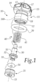
- the device for protecting an electric pump against overpressures is shown on its own in the exploded view of Figure 1 , in which it is designated generally by the reference numeral 10.
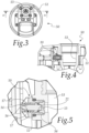
- the device 10 is designed to be mounted in an electric pump 50 according to the invention, shown in Figures 2 to 5 .
- the device 10 comprises a main body 11 which, together with a secondary body 21, forms a cavity 12 that has a substantially cylindrical and elongated shape along an axis of extension 100.
- the inlet 13 is formed by a through opening formed in the secondary body 21, which has a substantially cylindrical shape and is at least partially inserted in a fixed or removable manner in the cavity 12.
- the secondary body 21 is provided with a thread, not shown in the figures, which is threaded complementarily to the cavity 12.
- the outlet 14 is instead formed proximate to a contoured head 15 which protrudes axially from one end of the main body 11.
- the contoured head 15 is provided with a series of radial openings 17 in fluid communication with the outlet 14.
- the radial openings 17 are preferably configured so as to allow an outflow of the water along a direction that is transverse to the axis of extension 100.
- the contoured head 15 substantially has the shape of a prism with a hexagonal base on which a pyramid or a truncated pyramid lies and in which six radial openings 17 open.
- contoured head of the device according to the invention can have a variable shape and dimensions, and likewise the number and geometric characteristics of the radial openings may vary.
- a threaded portion 18 designed to be coupled to a corresponding complementarily threaded portion 54 of a coupling that is provided on the electric pump 50 and is arranged in fluid communication with the delivery port 53 of the latter.
- a first substantially annular groove 19 is provided on the outer surface of the main body 11 and is arranged between the contoured head 15 and the threaded portion 18.
- the first groove 19 is configured to accommodate first sealing means 20, for example a first O-ring, which are designed to be arranged between the contoured head 15 and said coupling provided on the electric pump 50 when the device 10 is mounted on said pump.
- first sealing means 20 for example a first O-ring
- a flow control element 30 is accommodated in the cavity 12 and can slide within the device 10 along the axis of extension 100.
- the flow control element 30 can move between a closed position, in which it affects the inlet 13, and an open position, in which the flow control element 30 clears at least partially the inlet 13 so as to place it in fluidic connection with the outlet 14.
- the delivery port 53 is in fluid connection with the environment in which the electric pump 50 is located.
- the flow control element 30 comprises a cylindrical body 35 from which a pin 31 protrudes, at an axial end; said pin is accommodated slidingly in a sliding seat 16 which is formed in the contoured head 15 and is substantially parallel to the axis of extension 100.
- a shoulder 32 is instead formed at the end of the flow control element 30 that is opposite the one from which the pin 31 protrudes and contributes to form a second groove 33 which is configured to accommodate second sealing means 34, which for example consist of a second O-ring.
- the second sealing means 34 are configured to cooperate, in the closed position, with an abutment seat 22 that is formed by the secondary body 21 around the inlet 13.
- the device 10 also comprises elastic means 40 which adjust the position of the flow control element 30 in response to the pressure that is present in the delivery port 53.
- the elastic means 40 consist of a spring 41 which is mounted coaxially on the flow control element 30.
- the two opposite ends of the spring 41 abut respectively against the shoulder 32 and against the inside of the contoured head 15.
- the spring 41 is calibrated so as to be compressed elastically when a preset pressure value is exceeded in the delivery port 53, so as to allow the axial sliding of the flow control element 30, producing the transition from the closed position to the open position.
- said threshold pressure can be set at a value of approximately 12 bars.
- the inlet 13 When the threshold pressure is exceeded, the inlet 13 is placed in fluid connection with the outlet 14 and accordingly the delivery port 53 is in fluid connection with the environment in which the electric pump 50 is located, an environment in which the water that caused the overpressure is expelled.
- the electric pump 50 is of the submersed or submersible type and comprises a pump body 51 which forms a chamber inside which one or more impellers, not visible in the figures and rotated by an electric motor, are accommodated.
- the chamber is provided with an intake port 52 and with the already mentioned delivery port 53.
- the electric pump 50 comprises a device 10, which is preferably mounted at the delivery port 53.
- the invention achieves the proposed aims and objects, providing a device for protecting an electric pump against overpressures that allows to compensate for or suppress instantaneous increases in the pressure of the fluid pumped by an electric pump and at the same time has a modest space occupation, so much that it can be installed substantially on any type of electric pump.
- the device according to the invention helps to avoid substantially all of the destructive phenomena linked to overpressures and even more particularly allows to contrast the phenomenon known as hammering.
- the device according to the invention is reliable and precise in operation in addition to being relatively simple to provide and obtainable at competitive costs.
- the materials used may be any according to the requirements and the state of the art.
Landscapes
- Engineering & Computer Science (AREA)
- General Engineering & Computer Science (AREA)
- Mechanical Engineering (AREA)
- Life Sciences & Earth Sciences (AREA)
- Sustainable Development (AREA)
- Chemical & Material Sciences (AREA)
- Combustion & Propulsion (AREA)
- Structures Of Non-Positive Displacement Pumps (AREA)
- Electrical Discharge Machining, Electrochemical Machining, And Combined Machining (AREA)
- Compressor (AREA)
- Emergency Protection Circuit Devices (AREA)
- Details Of Reciprocating Pumps (AREA)
- Details And Applications Of Rotary Liquid Pumps (AREA)
Claims (9)
- Getauchte oder tauchbare elektrische Pumpe (50), umfassend einen Pumpenkörper (51), der mit einer Kammer versehen ist, die angepasst ist, um mindestens ein Laufrad aufzunehmen, das durch Motoreinrichtungen gedreht wird, die Kammer umfassend mindestens einen Einlassanschluss (52) und mindestens einen Ausgabeanschluss (53), die Pumpe (50) ferner umfassend mindestens eine Vorrichtung (10) zum Schutz der elektrischen Pumpe (10) gegen Überdruck, die Vorrichtung (10) umfassend einen Hauptkörper (11), der einen Hohlraum (12) mit einer Erstreckungsachse (100) bildet, die im Wesentlichen parallel zu einer Erstreckungsachse des Hauptkörpers (11) ist, und ein Strömungssteuerelement (30), das in dem Hohlraum (12) entlang der Erstreckungsachse (100) des Hohlraums zwischen einer geschlossenen Position, in der das Durchflusssteuerelement (30) auf einen Einlass (13) des Hohlraums (12) einwirkt, der fluidisch mit einem Ausgabeanschluss (53) der elektrischen Pumpe (50) verbunden ist, und einer offenen Position, in der das Durchflusssteuerelement (30) den Einlass (13) zumindest teilweise freigibt, um ihn über einen Auslass (14) des Hohlraums (12) in fluidische Verbindung mit der Umgebung zu bringen, in der die elektrische Pumpe (50) angeordnet ist, gleiten kann, elastische Einrichtungen (40), die konstruiert sind, um das Durchflusssteuerelement (30) als Reaktion auf einen Druck zu schieben, der in dem Ausgabeanschluss (53) vorhanden ist, wobei die Vorrichtung (10) an dem Ausgabeanschluss (53) montiert ist.
- Pumpe (50) nach Anspruch 1, dadurch gekennzeichnet, dass der Hauptkörper (11) einen konturierten Kopf (15) umfasst, der mit einem Sitz (16) für das Gleiten eines Stifts (31) versehen ist, der aus dem Durchflusssteuerelement (30) hervorsteht, wobei der Gleitsitz (16) im Wesentlichen parallel zu der Erstreckungsachse (100) des Hohlraums gebildet ist.
- Pumpe (50) nach einem oder mehreren der vorherigen Ansprüche, dadurch gekennzeichnet, dass der Hauptkörper (11) eine Vielzahl von radialen Öffnungen (17) für den Ausfluss des Wassers aufweist, wobei die radialen Öffnungen (17) an dem konturierten Kopf (15) gebildet sind und mit dem Auslass (14) verbunden sind.
- Pumpe (50) nach einem oder mehreren der vorherigen Ansprüche, dadurch gekennzeichnet, dass der Hauptkörper (11) einen Gewindeabschnitt (18) zum Anschließen an einen komplementär mit einem Gewinde versehenen Abschnitt (54) einer Kupplung umfasst, die in Fluidverbindung mit dem Ausgabeanschluss (53) ist.
- Pumpe (50) nach einem oder mehreren der vorherigen Ansprüche, dadurch gekennzeichnet, dass der Hauptkörper (11) eine erste Nut (19) aufweist, die zwischen dem konturierten Kopf (15) und dem Gewindeabschnitt (18) angeordnet ist, wobei die erste Nut (19) angepasst ist, um erste Dichtungseinrichtungen (20) aufzunehmen, die zwischen dem konturierten Kopf (15) und der elektrischen Pumpe (50) im Wesentlichen an dem komplementären Gewindeabschnitt (54) angeordnet werden kann.
- Pumpe (50) nach einem oder mehreren der vorherigen Ansprüche, dadurch gekennzeichnet, dass sie einen Sekundärkörper (21) umfasst, der mit dem Hauptkörper (11) assoziiert ist und teilweise in den Hohlraum (12) eingesetzt ist, wobei der Sekundärkörper (21) den Einlass (13) und einen Anschlagsitz (22) für das Durchflusssteuerelement (30) bildet.
- Pumpe (50) nach einem oder mehreren der vorherigen Ansprüche, dadurch gekennzeichnet, dass das Durchflusssteuerelement (30) eine Schulter (32) umfasst, die an einer gegenüberliegenden Position in Bezug auf den Stift (31) bereitgestellt ist, wobei die Schulter (32) eine zweite Nut (33) bildet, die angepasst ist, um zweite Dichtungseinrichtungen (34) aufzunehmen, die in der geschlossenen Position mit dem Anschlagsitz (22) zusammenwirken.
- Pumpe (50) nach einem oder mehreren der vorherigen Ansprüche, dadurch gekennzeichnet, dass die elastischen Einrichtungen (40) mindestens eine Feder (41) umfassen, die koaxial an dem Durchflusssteuerelement (30) montiert ist, wobei die Feder (41) an der Schulter (32) und an dem konturierten Kopf (15) im Wesentlichen an dem Gleitsitz (16) anliegt.
- Pumpe (50) nach einem oder mehreren der vorherigen Ansprüche, dadurch gekennzeichnet, dass die Feder (41) kalibriert ist, um elastisch zusammengedrückt zu werden, wenn ein voreingestellter Druckwert in dem Ausgabeanschluss (53) überschritten wird, um das axiale Gleiten des Durchflusssteuerelements (30) zu ermöglichen und den Übergang von der geschlossenen Position zu der offenen Position zu bestimmen.
Applications Claiming Priority (1)
| Application Number | Priority Date | Filing Date | Title |
|---|---|---|---|
| IT102019000012855A IT201900012855A1 (it) | 2019-07-25 | 2019-07-25 | Dispositivo per la protezione da sovrappressioni di una elettropompa |
Publications (3)
| Publication Number | Publication Date |
|---|---|
| EP3770432A1 EP3770432A1 (de) | 2021-01-27 |
| EP3770432B1 true EP3770432B1 (de) | 2023-08-23 |
| EP3770432C0 EP3770432C0 (de) | 2023-08-23 |
Family
ID=68733487
Family Applications (1)
| Application Number | Title | Priority Date | Filing Date |
|---|---|---|---|
| EP20184373.7A Active EP3770432B1 (de) | 2019-07-25 | 2020-07-07 | Vorrichtung zum schutz einer elektrischen pumpe gegen überdrücke |
Country Status (4)
| Country | Link |
|---|---|
| US (1) | US11560896B2 (de) |
| EP (1) | EP3770432B1 (de) |
| ES (1) | ES2956863T3 (de) |
| IT (1) | IT201900012855A1 (de) |
Families Citing this family (2)
| Publication number | Priority date | Publication date | Assignee | Title |
|---|---|---|---|---|
| US11725532B1 (en) * | 2022-05-30 | 2023-08-15 | Pratt & Whitney Canada Corp. | Switching valve |
| US11939874B2 (en) | 2022-06-02 | 2024-03-26 | Pratt & Whitney Canada Corp. | Switching valve |
Family Cites Families (8)
| Publication number | Priority date | Publication date | Assignee | Title |
|---|---|---|---|---|
| US2786485A (en) * | 1951-08-13 | 1957-03-26 | Lois Stcirly Rozzell | Slush pump valve |
| US2949928A (en) * | 1958-01-16 | 1960-08-23 | Plastering Dev Ct Inc | Valve |
| US3702141A (en) * | 1971-02-22 | 1972-11-07 | Dresser Ind | Gas type safety valve |
| US3756273A (en) * | 1971-11-22 | 1973-09-04 | R Hengesbach | Valve |
| JPS59103087A (ja) * | 1982-12-02 | 1984-06-14 | N T C Kogyo Kk | 圧力安全弁装置 |
| DE4028606A1 (de) * | 1990-09-08 | 1992-03-26 | Teves Gmbh Alfred | Druckregelventil, insbesondere zur druckmittelsteuerung in schlupfgeregelten, hydraulischen bremsanlagen |
| JP2002235625A (ja) * | 2000-12-07 | 2002-08-23 | Mitsubishi Electric Corp | 電動燃料ポンプ |
| ITMO20070236A1 (it) * | 2007-07-13 | 2009-01-14 | Vanna Zaccarelli | "macchina per il pompaggio di fluidi" |
-
2019
- 2019-07-25 IT IT102019000012855A patent/IT201900012855A1/it unknown
-
2020
- 2020-07-07 EP EP20184373.7A patent/EP3770432B1/de active Active
- 2020-07-07 ES ES20184373T patent/ES2956863T3/es active Active
- 2020-07-22 US US16/935,737 patent/US11560896B2/en active Active
Also Published As
| Publication number | Publication date |
|---|---|
| US11560896B2 (en) | 2023-01-24 |
| ES2956863T3 (es) | 2023-12-29 |
| US20210025400A1 (en) | 2021-01-28 |
| EP3770432A1 (de) | 2021-01-27 |
| EP3770432C0 (de) | 2023-08-23 |
| IT201900012855A1 (it) | 2021-01-25 |
Similar Documents
| Publication | Publication Date | Title |
|---|---|---|
| EP3770432B1 (de) | Vorrichtung zum schutz einer elektrischen pumpe gegen überdrücke | |
| CA2937258C (en) | Filter for hydraulic fluids for hydraulic circuits and process of making the same | |
| MX2008013538A (es) | Bomba accionada por aire con control de rendimiento. | |
| JP4081437B2 (ja) | インレットボール移動行程の調節が可能な往復ピストンポンプ | |
| US10167965B2 (en) | Non return valve for use in water line | |
| EP1756454B1 (de) | Stromregelventil | |
| EP3730797B1 (de) | Rückschlagventil für eine tauchpumpe und zugehörige tauchpumpe | |
| US20100006570A1 (en) | Valve, container with valve and use of the valve | |
| US4265274A (en) | Pulsation dampener for low output systems | |
| CA2940851A1 (en) | Bilge pump having concealed air-lock vent | |
| NO164936B (no) | Belgpumpe med kontinuerlig innstroemming og pulserende utstroemming. | |
| EP3514420A1 (de) | Fünfwegeventil | |
| JP4865622B2 (ja) | ミニフロー弁 | |
| EP3770436B1 (de) | Elektrische pumpe mit entlüftungsvorrichtung | |
| KR101793791B1 (ko) | 유로 차단 기능을 구비한 감압밸브 장치 | |
| WO2015130620A2 (en) | Anti-airlock valve assembly | |
| EP3812587B1 (de) | Membranpumpe | |
| EP2882903B1 (de) | Abdeckung einer pumpe | |
| US20090317274A1 (en) | Hydraulic pump | |
| EP3311027B1 (de) | Entlüftungsventil und selbstentlüftungspumpe mit solch einem ventil | |
| CN110553069B (zh) | 一种流体稳压阀 | |
| KR102404819B1 (ko) | 우물용 싱글제트 | |
| KR102806186B1 (ko) | 변속기 유압공급장치 | |
| RU2228467C2 (ru) | Гидравлическая система с аварийной защитой | |
| JP2020148218A (ja) | 液体の圧送装置 |
Legal Events
| Date | Code | Title | Description |
|---|---|---|---|
| PUAI | Public reference made under article 153(3) epc to a published international application that has entered the european phase |
Free format text: ORIGINAL CODE: 0009012 |
|
| STAA | Information on the status of an ep patent application or granted ep patent |
Free format text: STATUS: THE APPLICATION HAS BEEN PUBLISHED |
|
| AK | Designated contracting states |
Kind code of ref document: A1 Designated state(s): AL AT BE BG CH CY CZ DE DK EE ES FI FR GB GR HR HU IE IS IT LI LT LU LV MC MK MT NL NO PL PT RO RS SE SI SK SM TR |
|
| AX | Request for extension of the european patent |
Extension state: BA ME |
|
| STAA | Information on the status of an ep patent application or granted ep patent |
Free format text: STATUS: REQUEST FOR EXAMINATION WAS MADE |
|
| 17P | Request for examination filed |
Effective date: 20210607 |
|
| RBV | Designated contracting states (corrected) |
Designated state(s): AL AT BE BG CH CY CZ DE DK EE ES FI FR GB GR HR HU IE IS IT LI LT LU LV MC MK MT NL NO PL PT RO RS SE SI SK SM TR |
|
| STAA | Information on the status of an ep patent application or granted ep patent |
Free format text: STATUS: EXAMINATION IS IN PROGRESS |
|
| 17Q | First examination report despatched |
Effective date: 20211116 |
|
| GRAP | Despatch of communication of intention to grant a patent |
Free format text: ORIGINAL CODE: EPIDOSNIGR1 |
|
| STAA | Information on the status of an ep patent application or granted ep patent |
Free format text: STATUS: GRANT OF PATENT IS INTENDED |
|
| INTG | Intention to grant announced |
Effective date: 20230516 |
|
| P01 | Opt-out of the competence of the unified patent court (upc) registered |
Effective date: 20230515 |
|
| GRAS | Grant fee paid |
Free format text: ORIGINAL CODE: EPIDOSNIGR3 |
|
| GRAA | (expected) grant |
Free format text: ORIGINAL CODE: 0009210 |
|
| STAA | Information on the status of an ep patent application or granted ep patent |
Free format text: STATUS: THE PATENT HAS BEEN GRANTED |
|
| AK | Designated contracting states |
Kind code of ref document: B1 Designated state(s): AL AT BE BG CH CY CZ DE DK EE ES FI FR GB GR HR HU IE IS IT LI LT LU LV MC MK MT NL NO PL PT RO RS SE SI SK SM TR |
|
| REG | Reference to a national code |
Ref country code: GB Ref legal event code: FG4D |
|
| REG | Reference to a national code |
Ref country code: CH Ref legal event code: EP |
|
| REG | Reference to a national code |
Ref country code: IE Ref legal event code: FG4D |
|
| REG | Reference to a national code |
Ref country code: DE Ref legal event code: R096 Ref document number: 602020016097 Country of ref document: DE |
|
| P04 | Withdrawal of opt-out of the competence of the unified patent court (upc) registered |
Effective date: 20230925 |
|
| U01 | Request for unitary effect filed |
Effective date: 20230922 |
|
| U07 | Unitary effect registered |
Designated state(s): AT BE BG DE DK EE FI FR IT LT LU LV MT NL PT SE SI Effective date: 20230927 |
|
| REG | Reference to a national code |
Ref country code: ES Ref legal event code: FG2A Ref document number: 2956863 Country of ref document: ES Kind code of ref document: T3 Effective date: 20231229 |
|
| PG25 | Lapsed in a contracting state [announced via postgrant information from national office to epo] |
Ref country code: GR Free format text: LAPSE BECAUSE OF FAILURE TO SUBMIT A TRANSLATION OF THE DESCRIPTION OR TO PAY THE FEE WITHIN THE PRESCRIBED TIME-LIMIT Effective date: 20231124 |
|
| PG25 | Lapsed in a contracting state [announced via postgrant information from national office to epo] |
Ref country code: IS Free format text: LAPSE BECAUSE OF FAILURE TO SUBMIT A TRANSLATION OF THE DESCRIPTION OR TO PAY THE FEE WITHIN THE PRESCRIBED TIME-LIMIT Effective date: 20231223 |
|
| PG25 | Lapsed in a contracting state [announced via postgrant information from national office to epo] |
Ref country code: RS Free format text: LAPSE BECAUSE OF FAILURE TO SUBMIT A TRANSLATION OF THE DESCRIPTION OR TO PAY THE FEE WITHIN THE PRESCRIBED TIME-LIMIT Effective date: 20230823 Ref country code: NO Free format text: LAPSE BECAUSE OF FAILURE TO SUBMIT A TRANSLATION OF THE DESCRIPTION OR TO PAY THE FEE WITHIN THE PRESCRIBED TIME-LIMIT Effective date: 20231123 Ref country code: IS Free format text: LAPSE BECAUSE OF FAILURE TO SUBMIT A TRANSLATION OF THE DESCRIPTION OR TO PAY THE FEE WITHIN THE PRESCRIBED TIME-LIMIT Effective date: 20231223 Ref country code: HR Free format text: LAPSE BECAUSE OF FAILURE TO SUBMIT A TRANSLATION OF THE DESCRIPTION OR TO PAY THE FEE WITHIN THE PRESCRIBED TIME-LIMIT Effective date: 20230823 Ref country code: GR Free format text: LAPSE BECAUSE OF FAILURE TO SUBMIT A TRANSLATION OF THE DESCRIPTION OR TO PAY THE FEE WITHIN THE PRESCRIBED TIME-LIMIT Effective date: 20231124 |
|
| PG25 | Lapsed in a contracting state [announced via postgrant information from national office to epo] |
Ref country code: PL Free format text: LAPSE BECAUSE OF FAILURE TO SUBMIT A TRANSLATION OF THE DESCRIPTION OR TO PAY THE FEE WITHIN THE PRESCRIBED TIME-LIMIT Effective date: 20230823 |
|
| PG25 | Lapsed in a contracting state [announced via postgrant information from national office to epo] |
Ref country code: SM Free format text: LAPSE BECAUSE OF FAILURE TO SUBMIT A TRANSLATION OF THE DESCRIPTION OR TO PAY THE FEE WITHIN THE PRESCRIBED TIME-LIMIT Effective date: 20230823 Ref country code: RO Free format text: LAPSE BECAUSE OF FAILURE TO SUBMIT A TRANSLATION OF THE DESCRIPTION OR TO PAY THE FEE WITHIN THE PRESCRIBED TIME-LIMIT Effective date: 20230823 Ref country code: CZ Free format text: LAPSE BECAUSE OF FAILURE TO SUBMIT A TRANSLATION OF THE DESCRIPTION OR TO PAY THE FEE WITHIN THE PRESCRIBED TIME-LIMIT Effective date: 20230823 Ref country code: SK Free format text: LAPSE BECAUSE OF FAILURE TO SUBMIT A TRANSLATION OF THE DESCRIPTION OR TO PAY THE FEE WITHIN THE PRESCRIBED TIME-LIMIT Effective date: 20230823 |
|
| REG | Reference to a national code |
Ref country code: DE Ref legal event code: R097 Ref document number: 602020016097 Country of ref document: DE |
|
| PLBE | No opposition filed within time limit |
Free format text: ORIGINAL CODE: 0009261 |
|
| STAA | Information on the status of an ep patent application or granted ep patent |
Free format text: STATUS: NO OPPOSITION FILED WITHIN TIME LIMIT |
|
| U20 | Renewal fee for the european patent with unitary effect paid |
Year of fee payment: 5 Effective date: 20240607 |
|
| 26N | No opposition filed |
Effective date: 20240524 |
|
| P05 | Withdrawal of opt-out of the competence of the unified patent court (upc) changed |
Free format text: CASE NUMBER: APP_576398/2023 Effective date: 20230927 |
|
| PG25 | Lapsed in a contracting state [announced via postgrant information from national office to epo] |
Ref country code: MC Free format text: LAPSE BECAUSE OF FAILURE TO SUBMIT A TRANSLATION OF THE DESCRIPTION OR TO PAY THE FEE WITHIN THE PRESCRIBED TIME-LIMIT Effective date: 20230823 |
|
| REG | Reference to a national code |
Ref country code: CH Ref legal event code: PL |
|
| PG25 | Lapsed in a contracting state [announced via postgrant information from national office to epo] |
Ref country code: CH Free format text: LAPSE BECAUSE OF NON-PAYMENT OF DUE FEES Effective date: 20240731 |
|
| PGFP | Annual fee paid to national office [announced via postgrant information from national office to epo] |
Ref country code: GB Payment date: 20250529 Year of fee payment: 6 |
|
| PG25 | Lapsed in a contracting state [announced via postgrant information from national office to epo] |
Ref country code: IE Free format text: LAPSE BECAUSE OF NON-PAYMENT OF DUE FEES Effective date: 20240707 |
|
| U20 | Renewal fee for the european patent with unitary effect paid |
Year of fee payment: 6 Effective date: 20250709 |
|
| PGFP | Annual fee paid to national office [announced via postgrant information from national office to epo] |
Ref country code: ES Payment date: 20250807 Year of fee payment: 6 |
|
| PG25 | Lapsed in a contracting state [announced via postgrant information from national office to epo] |
Ref country code: CY Free format text: LAPSE BECAUSE OF FAILURE TO SUBMIT A TRANSLATION OF THE DESCRIPTION OR TO PAY THE FEE WITHIN THE PRESCRIBED TIME-LIMIT; INVALID AB INITIO Effective date: 20200707 |
|
| PG25 | Lapsed in a contracting state [announced via postgrant information from national office to epo] |
Ref country code: HU Free format text: LAPSE BECAUSE OF FAILURE TO SUBMIT A TRANSLATION OF THE DESCRIPTION OR TO PAY THE FEE WITHIN THE PRESCRIBED TIME-LIMIT; INVALID AB INITIO Effective date: 20200707 |