EP3770436B1 - Elektrische pumpe mit entlüftungsvorrichtung - Google Patents
Elektrische pumpe mit entlüftungsvorrichtung Download PDFInfo
- Publication number
- EP3770436B1 EP3770436B1 EP20184144.2A EP20184144A EP3770436B1 EP 3770436 B1 EP3770436 B1 EP 3770436B1 EP 20184144 A EP20184144 A EP 20184144A EP 3770436 B1 EP3770436 B1 EP 3770436B1
- Authority
- EP
- European Patent Office
- Prior art keywords
- electric pump
- pump
- pump body
- extension
- inlet
- Prior art date
- Legal status (The legal status is an assumption and is not a legal conclusion. Google has not performed a legal analysis and makes no representation as to the accuracy of the status listed.)
- Active
Links
Images

Classifications
-
- F—MECHANICAL ENGINEERING; LIGHTING; HEATING; WEAPONS; BLASTING
- F04—POSITIVE - DISPLACEMENT MACHINES FOR LIQUIDS; PUMPS FOR LIQUIDS OR ELASTIC FLUIDS
- F04D—NON-POSITIVE-DISPLACEMENT PUMPS
- F04D13/00—Pumping installations or systems
- F04D13/02—Units comprising pumps and their driving means
- F04D13/06—Units comprising pumps and their driving means the pump being electrically driven
-
- F—MECHANICAL ENGINEERING; LIGHTING; HEATING; WEAPONS; BLASTING
- F04—POSITIVE - DISPLACEMENT MACHINES FOR LIQUIDS; PUMPS FOR LIQUIDS OR ELASTIC FLUIDS
- F04D—NON-POSITIVE-DISPLACEMENT PUMPS
- F04D15/00—Control, e.g. regulation, of pumps, pumping installations or systems
- F04D15/0005—Control, e.g. regulation, of pumps, pumping installations or systems by using valves
-
- F—MECHANICAL ENGINEERING; LIGHTING; HEATING; WEAPONS; BLASTING
- F04—POSITIVE - DISPLACEMENT MACHINES FOR LIQUIDS; PUMPS FOR LIQUIDS OR ELASTIC FLUIDS
- F04D—NON-POSITIVE-DISPLACEMENT PUMPS
- F04D9/00—Priming; Preventing vapour lock
- F04D9/004—Priming of not self-priming pumps
- F04D9/006—Priming of not self-priming pumps by venting gas or using gas valves
Definitions
- the present invention relates to an electric pump with air venting device and also relates to said device.
- Electric pumps with such air venting devices are disclosed for example in documents US 2015/247501 A1 , US 4 834 621 A or EP 2 730 826 A1 .
- electric pumps are electrically actuated hydraulic machines adapted to lift or move liquids, which once aspirated are directed toward user devices of various kinds.
- the installation of a submersed electric pump therefore entails its immersion in the water or in the liquid to be pumped.
- This operation can give rise to an unwanted accumulation of air, a sort of "diving bell", inside the intake duct of the electric pump and the body of the latter.
- Some submersed electric pumps do not start autonomously in such cases and if the circuit is not filled with water the pump runs dry, with the risk of being damaged.
- the aim of the present invention is to provide an electric pump and a device that overcome the drawbacks of the cited background art.
- an object of the invention is to provide a device that allows to expel externally the air that has accumulated inside a submersed electric pump during its immersion in the pumping liquid.
- Another object of the invention is to provide a device that is structured to be installed and/or adapted outside the original assembly of a submersed electric pump.
- Another object of the invention is to provide a submersed electric pump in which said device can be applied to the priming connector and, depending on the various requirements, can be replaced with an ordinary plug.
- Another object of the invention is to provide a device that is relatively simple to provide and can be obtained at competitive costs.
- a device for venting air from an electric pump comprising a body which can be associated detachably with a pump body of an electric pump, wherein said body comprises at least one cavity having a substantially longitudinal axis of extension, said cavity having at least one inlet which can be connected fluidically to the inside of said pump body and at least one outlet which can be connected fluidically to the outside of said pump body, valve means arranged inside said cavity being adapted to adjust a flow of fluid between said inlet and said outlet as a function of the difference in pressure between the inside of said pump body and the outside of said pump body, a contoured head provided with a cross-shaped and/or rectilinear slot, and a threaded portion for coupling to a complementary threaded portion of a coupling in fluidic connection with the inside of said pump body, said threaded portion being longitudinally opposite with respect to said contoured head.
- the invention also relates to an electric pump comprising a pump body which has a chamber adapted to accommodate at least one impeller which is turned by electric motor means, said chamber comprising at least one intake port and at least one delivery port which is located at the outlet of a delivery duct, said electric pump being characterized in that it comprises said air venting device.
- the device for venting the air of an electric pump is shown on its own in the exploded view of Figure 1 , where it is designated generally by the reference numeral 10.
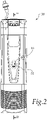
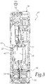
- the device 10 is adapted to be mounted in an electric pump 50 according to the invention, shown in Figures 2 to 4 .
- the device 10 comprises a plug-like body 11, which forms a cavity 12 that has an elongated shape and is extended predominantly along an axis of extension X.
- an inlet 13 adapted to be placed in fluid connection with the inside of a pump body 51 of the electric pump 50 so as to affect its delivery duct 60
- an outlet 14 adapted to be placed in fluid connection with the outside of the pump body 51, i.e., with the environment in which the electric pump 50 is placed.
- valve means 20 which adjust a flow of fluid between the inlet 13 and the outlet 14 as a function of the difference in pressure that exists between the inside of the pump body 51 and the outside thereof.
- valve means 20 comprise a spherical flow control element 21 which is accommodated in a central portion 12a of the cavity 12 and has a substantially cylindrical shape.
- the spherical flow control element 21 can move alternately along the axis of extension X and can affect selectively by gravity the inlet 13 of the cavity 12.
- the spherical flow control element 21 is guided in its alternating linear motion by a series of ribs 15 that protrude from the internal face of the central portion 12a and are extended substantially parallel to the axis of extension X.
- the valve means 20 furthermore comprise a tubular insert 22, made of a flexible material such as for example the rubber known by the trade name "FOODGUM/55/N", inserted in a wider portion 12c of the cavity 12 that is formed at one end of the central portion 12a.
- a tubular insert 22 made of a flexible material such as for example the rubber known by the trade name "FOODGUM/55/N"
- the winder portion 12c has a substantially cylindrical shape and a larger diameter than the central portion 12a.
- a calibrated passage is provided centrally to the tubular insert 22 and in practice forms the inlet 13.
- an abutment seat 23 that is adapted to cooperate with the spherical flow control element 21 in an inactive condition of the device 10 and of the electric pump 50.
- the spherical flow control element 21 is instead adapted to interact with a flared portion 12b of the cavity 12, which is formed at the end of the central portion 12a that is opposite the one in which the wider portion 12c is provided.
- the flared portion 12b has a substantially frustum-like shape and its internal surface converges in a main portion 14a of the outlet 14 that is coaxial with the axis of extension X.
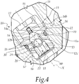
- the main portion 14a is divided into a plurality of branches 14b which are transverse to the axis of extension X, only one of which is shown in Figure 4 , which place the inside of the cavity 12 in fluid connection with the outside of the pump body 51.
- the branches 14b are provided in a contoured head 16 that is arranged at an axial end of the body 11.
- the contoured head 16 has a substantially cylindrical shape and two opposite branches 14b are provided therein.
- the shape and the dimensions of the contoured head of the device according to the invention can be variable, and likewise the number and the geometric characteristics of said branches can be variable.
- the contoured head 16 is provided with a cross-shaped or rectilinear slot 17 adapted to be engaged with a screwdriver.
- a threaded portion 18 that is adapted to couple to a corresponding complementarily threaded portion 57 of a coupling provided on the electric pump 50 and arranged in fluid connection with the inside of the pump body 51, so as to affect the delivery duct 60.
- the body 11 has, on its outer surface, a substantially annular groove 19, which is formed between the contoured head 16 and the threaded portion 18.
- the groove 19 is configured to accommodate sealing means 30, for example an O-ring, which are adapted to be arranged between the contoured head 16 and said coupling provided on the electric pump 50 when the device 10 is mounted on the latter.
- the electric pump 50 is of the submersed or submersible type and comprises the pump body 51, which forms a chamber 52 inside which one or more impellers 53 are accommodated which are turned by electric motor means 54.
- the chamber 52 has an intake port 55 and a delivery port 56, which is arranged at the output of a delivery duct 60.
- the electric pump 50 according to the invention comprises a device 10 according to the invention, which is preferably mounted at a complementarily threaded portion 57 of a coupling in fluid connection with the inside of the pump body 51.
- the complementarily threaded portion 57 of the coupling in fluid connection with the inside of the pump body 51 is arranged so as to affect the delivery duct 60.
- the spherical flow control element 21 affects by gravity the inlet 13 of the cavity 12 in cooperation with the abutment seat 23 of the tubular insert 22.
- the pressure of the air that flows through the inlet 13 gradually overcomes the inertia of the spherical flow control element 21, making it slide in the central portion 12a of the cavity 12 along the axis of extension X.
- the air By passing through the spaces which, by virtue of the ribs 15, are created between the spherical flow control element 21 and the internal surface of the central portion 12a, the air therefore flows toward the flared portion 12b, first entering the main portion 14a of the outlet 14 and then entering the branches 14b through which it is dispersed into the environment in which the electric pump 50 is immersed.
- the impellers 53 When the electric pump 50 is started, the impellers 53, actuated by the electric motor means 54, aspirate water through the intake port 55, pushing it under pressure toward the delivery port 56 through the duct 60.
- the pressurized water flows through the inlet 13 and by suddenly overcoming the inertia of the spherical flow control element 21 makes it slide in the central portion 12a of the cavity 12 along the axis of extension X, until it pushes it toward the flared portion 12b, where it affects the outlet 14, avoiding losses of pressure and in practice sealing the inside of the pump body 51 from the air.
- the device 10 can be replaced with an ordinary plug that has a substantially similar shape and the coupling provided with the complementarily threaded portion 57, being in fluid connection with the inside of the pump body 51, can be used to prime the electric pump 50.
- the invention achieves the intended aim and objects, providing a device and an electric pump which are capable of expelling externally the air that has accumulated inside the electric pump itself, for example during immersion in the pumping liquid.
- the device according to the invention is substantially structured like a plug and therefore can be installed and/or adapted outside the original assembly of the electric pump according to the invention.
- the materials used may be any according to the requirements and the state of the art.
Landscapes
- Engineering & Computer Science (AREA)
- Mechanical Engineering (AREA)
- General Engineering & Computer Science (AREA)
- Structures Of Non-Positive Displacement Pumps (AREA)
- Self-Closing Valves And Venting Or Aerating Valves (AREA)
Claims (9)
- Vorrichtung (10) zum Entlüften einer Elektropumpe, umfassend einen Körper (11), der lösbar mit einem Pumpenkörper (51) einer Elektropumpe (50) verbunden werden kann, wobei der besagte Körper (11) mindestens einen Hohlraum (12) mit einer im Wesentlichen längsgerichteten Erstreckungsachse (X) umfasst, wobei der besagte Hohlraum (12) mindestens einen Einlass (13) besitzt, der mit dem Inneren des Pumpenkörpers (51) strömungstechnisch verbindbar ist, und mindestens einen Auslass (14) aufweist, der strömungstechnisch mit der Außenseite des besagten Pumpenkörpers (51) verbindbar ist, wobei Ventile (20), die innerhalb des besagten Hohlraums (12) angeordnet sind, angepasst sind, um eine Fluidströmung zwischen dem besagten Einlass (13) und dem besagten Auslass (14) als Funktion der Druckdifferenz zwischen dem Inneren des besagten Pumpenkörpers (51) und dem Äußeren des besagten Pumpenkörpers (51) zu regulieren, dadurch gekennzeichnet, dass der besagte Körper (11) einen konturierten Kopf (16) umfasst, der mit einem kreuzförmigen (17) und/oder geradlinigen Schlitz versehen ist, und der besagte Körper (11) einen Gewindeabschnitt (18) zum Koppeln mit einem dazu passenden Gewindeabschnitt (57) einer Kupplung in flüssiger Verbindung mit dem Inneren des besagten Pumpenkörpers (51) umfasst, wobei der besagte Gewindeabschnitt (18) in Längsrichtung dem besagten konturierten Kopf (16) gegenüberliegt.
- Vorrichtung (10) nach Anspruch 1, dadurch gekennzeichnet, dass der besagte Hohlraum (12) einen im Wesentlichen zylindrischen Mittelabschnitt (12a) umfasst, wobei an den gegenüberliegenden Enden des besagten Mittelabschnitts (12a) ein im Wesentlichen kegelstumpfförmig aufgeweiteter Abschnitt (12b) vorhanden ist, der strömungstechnisch mit dem besagten Auslass (14) verbunden ist, und einen im Wesentlichen zylindrischen breiteren Abschnitt (12c), der strömungstechnisch mit dem besagten Einlass (13) verbunden ist.
- Vorrichtung (10) nach einem oder mehreren der vorhergehenden Ansprüche, dadurch gekennzeichnet, dass der besagte Auslass (14) einen Hauptabschnitt (14a) umfasst, der im Wesentlichen koaxial zu der besagten Erstreckungsachse (X) ist, und eine Vielzahl von Abzweigungen (14b), die quer zur besagten Erstreckungsachse (X) verlaufen und mit dem besagten Hauptabschnitt (14a) strömungstechnisch verbunden sind.
- Vorrichtung (10) nach einem oder mehreren der vorhergehenden Ansprüche, dadurch gekennzeichnet, dass die besagten Ventile (20) mindestens ein kugelförmiges Strömungssteuerelement (21) umfassen, das in dem besagten Mittelabschnitt (12a) untergebracht ist und sich abwechselnd entlang der besagten Erstreckungsachse (X) bewegen kann, wobei das besagte kugelförmige Strömungssteuerelement (21) angepasst ist, den besagten Einlass (13) durch Schwerkraft selektiv zu beeinflussen.
- Vorrichtung (10) nach einem oder mehreren der vorhergehenden Ansprüche, dadurch gekennzeichnet, dass sie eine Vielzahl von Rippen (15) umfasst, die von der Innenfläche des besagten zentralen Abschnitts (12a) vorstehen, wobei die besagten Rippen (15) eine Verlängerung haben, die im Wesentlichen parallel zu der besagten Erstreckungsachse (X) verläuft und angepasst ist, die abwechselnde lineare Bewegung des besagten kugelförmigen Strömungssteuerelements (21) zu führen.
- Vorrichtung (10) nach einem oder mehreren der vorhergehenden Ansprüche, dadurch gekennzeichnet, dass die besagten Ventile (20) einen röhrenförmigen Einsatz (22) umfassen, der in den besagten breiteren Abschnitt (12c) eingesetzt ist, wobei der besagte röhrenförmige Einsatz (22) den besagten Einlass (13) bildet, und einen Widerlagersitz (23) für das besagte kugelförmige Strömungssteuerelement (21).
- Vorrichtung (10) nach einem oder mehreren der vorhergehenden Ansprüche, dadurch gekennzeichnet, dass der besagte Körper (11) eine Nut (19) umfasst, die zwischen dem besagten konturierten Kopf (16) und dem besagten Gewindeabschnitt (18) angeordnet ist, wobei die besagte Nut (19) angepasst ist, um Dichtmittel (30) aufzunehmen, die zwischen dem besagten konturierten Kopf (16) und der besagten elektrischen Pumpe (51) im Wesentlichen an dem besagten, dazu passenden anderen mit Gewinde versehenen Abschnitt (57) angeordnet werden können.
- Elektrische Pumpe (50), die einen Pumpenkörper (51) umfasst, der eine Kammer (52) aufweist, die angepasst ist, mindestens ein Laufrad (53) aufzunehmen, das durch einen Elektromotor (54) gedreht wird, wobei die besagte Kammer (52) mindestens eine Ansaugöffnung (55) und mindestens einer Abgabeöffnung (56) umfasst, die sich am Ausgang einer Abgabeleitung (16) befindet, wobei die besagte elektrische Pumpe (50) dadurch gekennzeichnet ist, dass sie mindestens eine Vorrichtung (10) zum Entlüften der Luft einer Elektropumpe nach einem der vorhergehenden Ansprüche umfasst.
- Elektrischen Pumpe (50) nach Anspruch 8, dadurch gekennzeichnet, dass die besagte Vorrichtung (10) an einem dazu passenden anderen Gewindeabschnitt (57) einer Kupplung sich in flüssiger Verbindung mit der Innenseite des besagten Pumpenkörpers (51) befindet.
Applications Claiming Priority (1)
| Application Number | Priority Date | Filing Date | Title |
|---|---|---|---|
| IT102019000012861A IT201900012861A1 (it) | 2019-07-25 | 2019-07-25 | Elettropompa con dispositivo perfezionato di sfiato dell'aria |
Publications (2)
| Publication Number | Publication Date |
|---|---|
| EP3770436A1 EP3770436A1 (de) | 2021-01-27 |
| EP3770436B1 true EP3770436B1 (de) | 2023-01-04 |
Family
ID=69173120
Family Applications (1)
| Application Number | Title | Priority Date | Filing Date |
|---|---|---|---|
| EP20184144.2A Active EP3770436B1 (de) | 2019-07-25 | 2020-07-06 | Elektrische pumpe mit entlüftungsvorrichtung |
Country Status (3)
| Country | Link |
|---|---|
| EP (1) | EP3770436B1 (de) |
| ES (1) | ES2936325T3 (de) |
| IT (1) | IT201900012861A1 (de) |
Family Cites Families (3)
| Publication number | Priority date | Publication date | Assignee | Title |
|---|---|---|---|---|
| US4834621A (en) * | 1987-11-24 | 1989-05-30 | Apco/Valve And Primer Corporation | Air throttling valve for submerged pump system |
| ITPD20120344A1 (it) * | 2012-11-13 | 2014-05-14 | Dab Pumps Spa | Tappo da far cooperare con un otturatore di valvola per elettropompa autoadescante |
| US20150247501A1 (en) * | 2014-02-28 | 2015-09-03 | Flow Control LLC | Anti-airlock valve assembly |
-
2019
- 2019-07-25 IT IT102019000012861A patent/IT201900012861A1/it unknown
-
2020
- 2020-07-06 EP EP20184144.2A patent/EP3770436B1/de active Active
- 2020-07-06 ES ES20184144T patent/ES2936325T3/es active Active
Also Published As
| Publication number | Publication date |
|---|---|
| EP3770436A1 (de) | 2021-01-27 |
| ES2936325T3 (es) | 2023-03-16 |
| IT201900012861A1 (it) | 2021-01-25 |
Similar Documents
| Publication | Publication Date | Title |
|---|---|---|
| US3048121A (en) | Hydraulic actuated pump | |
| US5154821A (en) | Pool pump primer | |
| US5620309A (en) | Fluid pump priming system | |
| EP2894342B1 (de) | Selbstansaugende Zentrifugalpumpe | |
| CA2425449C (en) | Gas-lock re-prime device for submersible pumps | |
| US2986098A (en) | Expansible chamber liquid pump | |
| EP2405137A2 (de) | Pumpe | |
| US3250226A (en) | Hydraulic actuated pumping system | |
| EP3770436B1 (de) | Elektrische pumpe mit entlüftungsvorrichtung | |
| EP4431074A3 (de) | Spa-pool mit eingebautem aufblasbarem sitz | |
| CN103228917B (zh) | 可变排量的润滑剂泵 | |
| EP3770432B1 (de) | Vorrichtung zum schutz einer elektrischen pumpe gegen überdrücke | |
| CN111630274A (zh) | 深井泵及其使用方法 | |
| KR101758169B1 (ko) | 스퍼트 펌프용 임펠러 및 이를 이용한 스퍼트 펌프 | |
| CN112196751A (zh) | 一种柱塞泵 | |
| EP2894343B1 (de) | Selbstansaugende Zentrifugalpumpe | |
| US3761204A (en) | Positive displacement boosters | |
| EP2730826A1 (de) | Kappe zum Zusammenwirken mit einem Durchflussregelelement aus einem Ventil für eine selbstansaugende Elektropumpe | |
| CA2442553A1 (en) | Pump with axial conduit | |
| WO2019089912A1 (en) | Piston/liner configuration coordination in a piston pump | |
| CN215333653U (zh) | 具有加热装置的泵 | |
| EP1729009B1 (de) | Kreiselpumpe | |
| EP3204649B1 (de) | Hydrodynamische unterstützungsvorrichtung | |
| KR102411653B1 (ko) | 유체토출가이드를 구비한 다단원심펌프 | |
| RU2160390C1 (ru) | Резервированный электронасосный агрегат |
Legal Events
| Date | Code | Title | Description |
|---|---|---|---|
| PUAI | Public reference made under article 153(3) epc to a published international application that has entered the european phase |
Free format text: ORIGINAL CODE: 0009012 |
|
| STAA | Information on the status of an ep patent application or granted ep patent |
Free format text: STATUS: THE APPLICATION HAS BEEN PUBLISHED |
|
| AK | Designated contracting states |
Kind code of ref document: A1 Designated state(s): AL AT BE BG CH CY CZ DE DK EE ES FI FR GB GR HR HU IE IS IT LI LT LU LV MC MK MT NL NO PL PT RO RS SE SI SK SM TR |
|
| AX | Request for extension of the european patent |
Extension state: BA ME |
|
| STAA | Information on the status of an ep patent application or granted ep patent |
Free format text: STATUS: REQUEST FOR EXAMINATION WAS MADE |
|
| 17P | Request for examination filed |
Effective date: 20210607 |
|
| RBV | Designated contracting states (corrected) |
Designated state(s): AL AT BE BG CH CY CZ DE DK EE ES FI FR GB GR HR HU IE IS IT LI LT LU LV MC MK MT NL NO PL PT RO RS SE SI SK SM TR |
|
| GRAP | Despatch of communication of intention to grant a patent |
Free format text: ORIGINAL CODE: EPIDOSNIGR1 |
|
| STAA | Information on the status of an ep patent application or granted ep patent |
Free format text: STATUS: GRANT OF PATENT IS INTENDED |
|
| RIC1 | Information provided on ipc code assigned before grant |
Ipc: F04D 15/00 20060101ALI20221004BHEP Ipc: F04D 13/06 20060101ALI20221004BHEP Ipc: F04D 9/00 20060101AFI20221004BHEP |
|
| INTG | Intention to grant announced |
Effective date: 20221018 |
|
| GRAS | Grant fee paid |
Free format text: ORIGINAL CODE: EPIDOSNIGR3 |
|
| GRAA | (expected) grant |
Free format text: ORIGINAL CODE: 0009210 |
|
| STAA | Information on the status of an ep patent application or granted ep patent |
Free format text: STATUS: THE PATENT HAS BEEN GRANTED |
|
| AK | Designated contracting states |
Kind code of ref document: B1 Designated state(s): AL AT BE BG CH CY CZ DE DK EE ES FI FR GB GR HR HU IE IS IT LI LT LU LV MC MK MT NL NO PL PT RO RS SE SI SK SM TR |
|
| REG | Reference to a national code |
Ref country code: GB Ref legal event code: FG4D |
|
| REG | Reference to a national code |
Ref country code: CH Ref legal event code: EP |
|
| REG | Reference to a national code |
Ref country code: AT Ref legal event code: REF Ref document number: 1542119 Country of ref document: AT Kind code of ref document: T Effective date: 20230115 |
|
| REG | Reference to a national code |
Ref country code: DE Ref legal event code: R096 Ref document number: 602020007308 Country of ref document: DE |
|
| REG | Reference to a national code |
Ref country code: IE Ref legal event code: FG4D |
|
| REG | Reference to a national code |
Ref country code: ES Ref legal event code: FG2A Ref document number: 2936325 Country of ref document: ES Kind code of ref document: T3 Effective date: 20230316 |
|
| REG | Reference to a national code |
Ref country code: LT Ref legal event code: MG9D |
|
| REG | Reference to a national code |
Ref country code: NL Ref legal event code: MP Effective date: 20230104 |
|
| REG | Reference to a national code |
Ref country code: AT Ref legal event code: MK05 Ref document number: 1542119 Country of ref document: AT Kind code of ref document: T Effective date: 20230104 |
|
| P01 | Opt-out of the competence of the unified patent court (upc) registered |
Effective date: 20230515 |
|
| PG25 | Lapsed in a contracting state [announced via postgrant information from national office to epo] |
Ref country code: NL Free format text: LAPSE BECAUSE OF FAILURE TO SUBMIT A TRANSLATION OF THE DESCRIPTION OR TO PAY THE FEE WITHIN THE PRESCRIBED TIME-LIMIT Effective date: 20230104 |
|
| PG25 | Lapsed in a contracting state [announced via postgrant information from national office to epo] |
Ref country code: RS Free format text: LAPSE BECAUSE OF FAILURE TO SUBMIT A TRANSLATION OF THE DESCRIPTION OR TO PAY THE FEE WITHIN THE PRESCRIBED TIME-LIMIT Effective date: 20230104 Ref country code: PT Free format text: LAPSE BECAUSE OF FAILURE TO SUBMIT A TRANSLATION OF THE DESCRIPTION OR TO PAY THE FEE WITHIN THE PRESCRIBED TIME-LIMIT Effective date: 20230504 Ref country code: NO Free format text: LAPSE BECAUSE OF FAILURE TO SUBMIT A TRANSLATION OF THE DESCRIPTION OR TO PAY THE FEE WITHIN THE PRESCRIBED TIME-LIMIT Effective date: 20230404 Ref country code: LV Free format text: LAPSE BECAUSE OF FAILURE TO SUBMIT A TRANSLATION OF THE DESCRIPTION OR TO PAY THE FEE WITHIN THE PRESCRIBED TIME-LIMIT Effective date: 20230104 Ref country code: LT Free format text: LAPSE BECAUSE OF FAILURE TO SUBMIT A TRANSLATION OF THE DESCRIPTION OR TO PAY THE FEE WITHIN THE PRESCRIBED TIME-LIMIT Effective date: 20230104 Ref country code: HR Free format text: LAPSE BECAUSE OF FAILURE TO SUBMIT A TRANSLATION OF THE DESCRIPTION OR TO PAY THE FEE WITHIN THE PRESCRIBED TIME-LIMIT Effective date: 20230104 Ref country code: AT Free format text: LAPSE BECAUSE OF FAILURE TO SUBMIT A TRANSLATION OF THE DESCRIPTION OR TO PAY THE FEE WITHIN THE PRESCRIBED TIME-LIMIT Effective date: 20230104 |
|
| PG25 | Lapsed in a contracting state [announced via postgrant information from national office to epo] |
Ref country code: SE Free format text: LAPSE BECAUSE OF FAILURE TO SUBMIT A TRANSLATION OF THE DESCRIPTION OR TO PAY THE FEE WITHIN THE PRESCRIBED TIME-LIMIT Effective date: 20230104 Ref country code: PL Free format text: LAPSE BECAUSE OF FAILURE TO SUBMIT A TRANSLATION OF THE DESCRIPTION OR TO PAY THE FEE WITHIN THE PRESCRIBED TIME-LIMIT Effective date: 20230104 Ref country code: IS Free format text: LAPSE BECAUSE OF FAILURE TO SUBMIT A TRANSLATION OF THE DESCRIPTION OR TO PAY THE FEE WITHIN THE PRESCRIBED TIME-LIMIT Effective date: 20230504 Ref country code: GR Free format text: LAPSE BECAUSE OF FAILURE TO SUBMIT A TRANSLATION OF THE DESCRIPTION OR TO PAY THE FEE WITHIN THE PRESCRIBED TIME-LIMIT Effective date: 20230405 Ref country code: FI Free format text: LAPSE BECAUSE OF FAILURE TO SUBMIT A TRANSLATION OF THE DESCRIPTION OR TO PAY THE FEE WITHIN THE PRESCRIBED TIME-LIMIT Effective date: 20230104 |
|
| REG | Reference to a national code |
Ref country code: DE Ref legal event code: R097 Ref document number: 602020007308 Country of ref document: DE |
|
| PG25 | Lapsed in a contracting state [announced via postgrant information from national office to epo] |
Ref country code: SM Free format text: LAPSE BECAUSE OF FAILURE TO SUBMIT A TRANSLATION OF THE DESCRIPTION OR TO PAY THE FEE WITHIN THE PRESCRIBED TIME-LIMIT Effective date: 20230104 Ref country code: RO Free format text: LAPSE BECAUSE OF FAILURE TO SUBMIT A TRANSLATION OF THE DESCRIPTION OR TO PAY THE FEE WITHIN THE PRESCRIBED TIME-LIMIT Effective date: 20230104 Ref country code: EE Free format text: LAPSE BECAUSE OF FAILURE TO SUBMIT A TRANSLATION OF THE DESCRIPTION OR TO PAY THE FEE WITHIN THE PRESCRIBED TIME-LIMIT Effective date: 20230104 Ref country code: DK Free format text: LAPSE BECAUSE OF FAILURE TO SUBMIT A TRANSLATION OF THE DESCRIPTION OR TO PAY THE FEE WITHIN THE PRESCRIBED TIME-LIMIT Effective date: 20230104 Ref country code: CZ Free format text: LAPSE BECAUSE OF FAILURE TO SUBMIT A TRANSLATION OF THE DESCRIPTION OR TO PAY THE FEE WITHIN THE PRESCRIBED TIME-LIMIT Effective date: 20230104 |
|
| PLBE | No opposition filed within time limit |
Free format text: ORIGINAL CODE: 0009261 |
|
| STAA | Information on the status of an ep patent application or granted ep patent |
Free format text: STATUS: NO OPPOSITION FILED WITHIN TIME LIMIT |
|
| PG25 | Lapsed in a contracting state [announced via postgrant information from national office to epo] |
Ref country code: SK Free format text: LAPSE BECAUSE OF FAILURE TO SUBMIT A TRANSLATION OF THE DESCRIPTION OR TO PAY THE FEE WITHIN THE PRESCRIBED TIME-LIMIT Effective date: 20230104 |
|
| 26N | No opposition filed |
Effective date: 20231005 |
|
| PG25 | Lapsed in a contracting state [announced via postgrant information from national office to epo] |
Ref country code: SI Free format text: LAPSE BECAUSE OF FAILURE TO SUBMIT A TRANSLATION OF THE DESCRIPTION OR TO PAY THE FEE WITHIN THE PRESCRIBED TIME-LIMIT Effective date: 20230104 |
|
| PG25 | Lapsed in a contracting state [announced via postgrant information from national office to epo] |
Ref country code: MC Free format text: LAPSE BECAUSE OF FAILURE TO SUBMIT A TRANSLATION OF THE DESCRIPTION OR TO PAY THE FEE WITHIN THE PRESCRIBED TIME-LIMIT Effective date: 20230104 |
|
| PG25 | Lapsed in a contracting state [announced via postgrant information from national office to epo] |
Ref country code: MC Free format text: LAPSE BECAUSE OF FAILURE TO SUBMIT A TRANSLATION OF THE DESCRIPTION OR TO PAY THE FEE WITHIN THE PRESCRIBED TIME-LIMIT Effective date: 20230104 |
|
| REG | Reference to a national code |
Ref country code: CH Ref legal event code: PL |
|
| REG | Reference to a national code |
Ref country code: BE Ref legal event code: MM Effective date: 20230731 |
|
| PG25 | Lapsed in a contracting state [announced via postgrant information from national office to epo] |
Ref country code: LU Free format text: LAPSE BECAUSE OF NON-PAYMENT OF DUE FEES Effective date: 20230706 |
|
| PG25 | Lapsed in a contracting state [announced via postgrant information from national office to epo] |
Ref country code: LU Free format text: LAPSE BECAUSE OF NON-PAYMENT OF DUE FEES Effective date: 20230706 |
|
| REG | Reference to a national code |
Ref country code: IE Ref legal event code: MM4A |
|
| PG25 | Lapsed in a contracting state [announced via postgrant information from national office to epo] |
Ref country code: CH Free format text: LAPSE BECAUSE OF NON-PAYMENT OF DUE FEES Effective date: 20230731 |
|
| PG25 | Lapsed in a contracting state [announced via postgrant information from national office to epo] |
Ref country code: BE Free format text: LAPSE BECAUSE OF NON-PAYMENT OF DUE FEES Effective date: 20230731 |
|
| PG25 | Lapsed in a contracting state [announced via postgrant information from national office to epo] |
Ref country code: IE Free format text: LAPSE BECAUSE OF NON-PAYMENT OF DUE FEES Effective date: 20230706 |
|
| PG25 | Lapsed in a contracting state [announced via postgrant information from national office to epo] |
Ref country code: IE Free format text: LAPSE BECAUSE OF NON-PAYMENT OF DUE FEES Effective date: 20230706 |
|
| PG25 | Lapsed in a contracting state [announced via postgrant information from national office to epo] |
Ref country code: BG Free format text: LAPSE BECAUSE OF FAILURE TO SUBMIT A TRANSLATION OF THE DESCRIPTION OR TO PAY THE FEE WITHIN THE PRESCRIBED TIME-LIMIT Effective date: 20230104 |
|
| PG25 | Lapsed in a contracting state [announced via postgrant information from national office to epo] |
Ref country code: BG Free format text: LAPSE BECAUSE OF FAILURE TO SUBMIT A TRANSLATION OF THE DESCRIPTION OR TO PAY THE FEE WITHIN THE PRESCRIBED TIME-LIMIT Effective date: 20230104 |
|
| PGFP | Annual fee paid to national office [announced via postgrant information from national office to epo] |
Ref country code: GB Payment date: 20250529 Year of fee payment: 6 |
|
| PGFP | Annual fee paid to national office [announced via postgrant information from national office to epo] |
Ref country code: FR Payment date: 20250610 Year of fee payment: 6 |
|
| PG25 | Lapsed in a contracting state [announced via postgrant information from national office to epo] |
Ref country code: CY Free format text: LAPSE BECAUSE OF FAILURE TO SUBMIT A TRANSLATION OF THE DESCRIPTION OR TO PAY THE FEE WITHIN THE PRESCRIBED TIME-LIMIT; INVALID AB INITIO Effective date: 20200706 |
|
| PG25 | Lapsed in a contracting state [announced via postgrant information from national office to epo] |
Ref country code: HU Free format text: LAPSE BECAUSE OF FAILURE TO SUBMIT A TRANSLATION OF THE DESCRIPTION OR TO PAY THE FEE WITHIN THE PRESCRIBED TIME-LIMIT; INVALID AB INITIO Effective date: 20200706 |
|
| PGFP | Annual fee paid to national office [announced via postgrant information from national office to epo] |
Ref country code: ES Payment date: 20250807 Year of fee payment: 6 |
|
| PGFP | Annual fee paid to national office [announced via postgrant information from national office to epo] |
Ref country code: DE Payment date: 20250528 Year of fee payment: 6 |
|
| PGFP | Annual fee paid to national office [announced via postgrant information from national office to epo] |
Ref country code: IT Payment date: 20250625 Year of fee payment: 6 |
|
| PG25 | Lapsed in a contracting state [announced via postgrant information from national office to epo] |
Ref country code: TR Free format text: LAPSE BECAUSE OF FAILURE TO SUBMIT A TRANSLATION OF THE DESCRIPTION OR TO PAY THE FEE WITHIN THE PRESCRIBED TIME-LIMIT Effective date: 20230104 |