EP3769381B1 - Steuerung von laserstrahlparametern durch kristallverschiebung - Google Patents
Steuerung von laserstrahlparametern durch kristallverschiebung Download PDFInfo
- Publication number
- EP3769381B1 EP3769381B1 EP19712732.7A EP19712732A EP3769381B1 EP 3769381 B1 EP3769381 B1 EP 3769381B1 EP 19712732 A EP19712732 A EP 19712732A EP 3769381 B1 EP3769381 B1 EP 3769381B1
- Authority
- EP
- European Patent Office
- Prior art keywords
- crystal
- parameter
- shift speed
- shifting
- linear crystal
- Prior art date
- Legal status (The legal status is an assumption and is not a legal conclusion. Google has not performed a legal analysis and makes no representation as to the accuracy of the status listed.)
- Active
Links
Images


Classifications
-
- H—ELECTRICITY
- H01—ELECTRIC ELEMENTS
- H01S—DEVICES USING THE PROCESS OF LIGHT AMPLIFICATION BY STIMULATED EMISSION OF RADIATION [LASER] TO AMPLIFY OR GENERATE LIGHT; DEVICES USING STIMULATED EMISSION OF ELECTROMAGNETIC RADIATION IN WAVE RANGES OTHER THAN OPTICAL
- H01S3/00—Lasers, i.e. devices using stimulated emission of electromagnetic radiation in the infrared, visible or ultraviolet wave range
- H01S3/10—Controlling the intensity, frequency, phase, polarisation or direction of the emitted radiation, e.g. switching, gating, modulating or demodulating
- H01S3/13—Stabilisation of laser output parameters, e.g. frequency or amplitude
-
- G—PHYSICS
- G01—MEASURING; TESTING
- G01J—MEASUREMENT OF INTENSITY, VELOCITY, SPECTRAL CONTENT, POLARISATION, PHASE OR PULSE CHARACTERISTICS OF INFRARED, VISIBLE OR ULTRAVIOLET LIGHT; COLORIMETRY; RADIATION PYROMETRY
- G01J1/00—Photometry, e.g. photographic exposure meter
- G01J1/42—Photometry, e.g. photographic exposure meter using electric radiation detectors
- G01J1/4257—Photometry, e.g. photographic exposure meter using electric radiation detectors applied to monitoring the characteristics of a beam, e.g. laser beam, headlamp beam
-
- G—PHYSICS
- G01—MEASURING; TESTING
- G01J—MEASUREMENT OF INTENSITY, VELOCITY, SPECTRAL CONTENT, POLARISATION, PHASE OR PULSE CHARACTERISTICS OF INFRARED, VISIBLE OR ULTRAVIOLET LIGHT; COLORIMETRY; RADIATION PYROMETRY
- G01J1/00—Photometry, e.g. photographic exposure meter
- G01J1/42—Photometry, e.g. photographic exposure meter using electric radiation detectors
- G01J1/429—Photometry, e.g. photographic exposure meter using electric radiation detectors applied to measurement of ultraviolet light
-
- G—PHYSICS
- G01—MEASURING; TESTING
- G01N—INVESTIGATING OR ANALYSING MATERIALS BY DETERMINING THEIR CHEMICAL OR PHYSICAL PROPERTIES
- G01N21/00—Investigating or analysing materials by the use of optical means, i.e. using sub-millimetre waves, infrared, visible or ultraviolet light
- G01N21/84—Systems specially adapted for particular applications
- G01N21/88—Investigating the presence of flaws or contamination
- G01N21/8806—Specially adapted optical and illumination features
-
- G—PHYSICS
- G02—OPTICS
- G02F—OPTICAL DEVICES OR ARRANGEMENTS FOR THE CONTROL OF LIGHT BY MODIFICATION OF THE OPTICAL PROPERTIES OF THE MEDIA OF THE ELEMENTS INVOLVED THEREIN; NON-LINEAR OPTICS; FREQUENCY-CHANGING OF LIGHT; OPTICAL LOGIC ELEMENTS; OPTICAL ANALOGUE/DIGITAL CONVERTERS
- G02F1/00—Devices or arrangements for the control of the intensity, colour, phase, polarisation or direction of light arriving from an independent light source, e.g. switching, gating or modulating; Non-linear optics
- G02F1/35—Non-linear optics
- G02F1/3525—Optical damage
-
- G—PHYSICS
- G02—OPTICS
- G02F—OPTICAL DEVICES OR ARRANGEMENTS FOR THE CONTROL OF LIGHT BY MODIFICATION OF THE OPTICAL PROPERTIES OF THE MEDIA OF THE ELEMENTS INVOLVED THEREIN; NON-LINEAR OPTICS; FREQUENCY-CHANGING OF LIGHT; OPTICAL LOGIC ELEMENTS; OPTICAL ANALOGUE/DIGITAL CONVERTERS
- G02F1/00—Devices or arrangements for the control of the intensity, colour, phase, polarisation or direction of light arriving from an independent light source, e.g. switching, gating or modulating; Non-linear optics
- G02F1/35—Non-linear optics
- G02F1/353—Frequency conversion, i.e. wherein a light beam is generated with frequency components different from those of the incident light beams
-
- H—ELECTRICITY
- H01—ELECTRIC ELEMENTS
- H01S—DEVICES USING THE PROCESS OF LIGHT AMPLIFICATION BY STIMULATED EMISSION OF RADIATION [LASER] TO AMPLIFY OR GENERATE LIGHT; DEVICES USING STIMULATED EMISSION OF ELECTROMAGNETIC RADIATION IN WAVE RANGES OTHER THAN OPTICAL
- H01S3/00—Lasers, i.e. devices using stimulated emission of electromagnetic radiation in the infrared, visible or ultraviolet wave range
- H01S3/0014—Monitoring arrangements not otherwise provided for
-
- H—ELECTRICITY
- H01—ELECTRIC ELEMENTS
- H01S—DEVICES USING THE PROCESS OF LIGHT AMPLIFICATION BY STIMULATED EMISSION OF RADIATION [LASER] TO AMPLIFY OR GENERATE LIGHT; DEVICES USING STIMULATED EMISSION OF ELECTROMAGNETIC RADIATION IN WAVE RANGES OTHER THAN OPTICAL
- H01S3/00—Lasers, i.e. devices using stimulated emission of electromagnetic radiation in the infrared, visible or ultraviolet wave range
- H01S3/005—Optical devices external to the laser cavity, specially adapted for lasers, e.g. for homogenisation of the beam or for manipulating laser pulses, e.g. pulse shaping
- H01S3/0092—Nonlinear frequency conversion, e.g. second harmonic generation [SHG] or sum- or difference-frequency generation outside the laser cavity
-
- G—PHYSICS
- G01—MEASURING; TESTING
- G01J—MEASUREMENT OF INTENSITY, VELOCITY, SPECTRAL CONTENT, POLARISATION, PHASE OR PULSE CHARACTERISTICS OF INFRARED, VISIBLE OR ULTRAVIOLET LIGHT; COLORIMETRY; RADIATION PYROMETRY
- G01J1/00—Photometry, e.g. photographic exposure meter
- G01J1/42—Photometry, e.g. photographic exposure meter using electric radiation detectors
- G01J1/4257—Photometry, e.g. photographic exposure meter using electric radiation detectors applied to monitoring the characteristics of a beam, e.g. laser beam, headlamp beam
- G01J2001/4261—Scan through beam in order to obtain a cross-sectional profile of the beam
-
- G—PHYSICS
- G01—MEASURING; TESTING
- G01N—INVESTIGATING OR ANALYSING MATERIALS BY DETERMINING THEIR CHEMICAL OR PHYSICAL PROPERTIES
- G01N21/00—Investigating or analysing materials by the use of optical means, i.e. using sub-millimetre waves, infrared, visible or ultraviolet light
- G01N21/84—Systems specially adapted for particular applications
- G01N21/88—Investigating the presence of flaws or contamination
- G01N21/8806—Specially adapted optical and illumination features
- G01N2021/8835—Adjustable illumination, e.g. software adjustable screen
-
- G—PHYSICS
- G01—MEASURING; TESTING
- G01N—INVESTIGATING OR ANALYSING MATERIALS BY DETERMINING THEIR CHEMICAL OR PHYSICAL PROPERTIES
- G01N21/00—Investigating or analysing materials by the use of optical means, i.e. using sub-millimetre waves, infrared, visible or ultraviolet light
- G01N21/84—Systems specially adapted for particular applications
- G01N21/88—Investigating the presence of flaws or contamination
- G01N21/95—Investigating the presence of flaws or contamination characterised by the material or shape of the object to be examined
- G01N21/9501—Semiconductor wafers
-
- G—PHYSICS
- G01—MEASURING; TESTING
- G01N—INVESTIGATING OR ANALYSING MATERIALS BY DETERMINING THEIR CHEMICAL OR PHYSICAL PROPERTIES
- G01N21/00—Investigating or analysing materials by the use of optical means, i.e. using sub-millimetre waves, infrared, visible or ultraviolet light
- G01N21/84—Systems specially adapted for particular applications
- G01N21/88—Investigating the presence of flaws or contamination
- G01N21/95—Investigating the presence of flaws or contamination characterised by the material or shape of the object to be examined
- G01N21/956—Inspecting patterns on the surface of objects
-
- H—ELECTRICITY
- H01—ELECTRIC ELEMENTS
- H01S—DEVICES USING THE PROCESS OF LIGHT AMPLIFICATION BY STIMULATED EMISSION OF RADIATION [LASER] TO AMPLIFY OR GENERATE LIGHT; DEVICES USING STIMULATED EMISSION OF ELECTROMAGNETIC RADIATION IN WAVE RANGES OTHER THAN OPTICAL
- H01S3/00—Lasers, i.e. devices using stimulated emission of electromagnetic radiation in the infrared, visible or ultraviolet wave range
- H01S3/005—Optical devices external to the laser cavity, specially adapted for lasers, e.g. for homogenisation of the beam or for manipulating laser pulses, e.g. pulse shaping
Definitions
- This disclosure relates in general to stabilizing ultraviolet (UV) beam parameters.
- This disclosure relates in particular to varying a shift speed of a non-linear crystal to control a UV beam parameter.
- laser apparatuses generate UV beams by directing a source beam to a non-linear crystal.
- the source beam is frequency converted to a higher frequency, producing a shorter wavelength beam.
- a 532 nm beam can be directed to a non-linear crystal to generate a 266 nm beam (the second harmonic wavelength of the 532 nm beam).
- a 1064 nm beam and a 532 nm beam can generate a 355 nm beam (the third harmonic wavelength of the 1064 nm beam).
- multiple crystals are necessary to convert a source beam to a desired UV beam wavelength.
- UV beam parameter drift manifests as unstable beam quality (M 2 ), unstable axial beam waist location (z 0 ), and unstable beam waist diameter (2 ⁇ 0 ) (among others).
- UV beam parameters can degrade due to bulk or surface degradation of the crystal.
- Bulk degradation can result from photo-assisted modifications of the crystal along the beam path inside the crystal and from related "compaction" of optical material.
- Bulk degradation causes increased thermal dephasing, and wavefront distortion, related to increasing absorption of the source and UV beams.
- Surface degradation can result from photo-assisted deposition and decomposition of contaminants of the crystal environment or by gradual destruction of the crystal surface (leading to unwanted wave front distortions or diffraction effects).
- US patent application with publication number US 2010/128343 discloses a wavelength conversion light source apparatus, including a fundamental wave light source configured to emit a fundamental wave, a nonlinear crystal configured to convert a wavelength of the fundamental wave by being irradiated with the fundamental wave and making the fundamental wave pass therethrough, and a movement unit configured to place the nonlinear crystal thereon and continuously move the nonlinear crystal within a plane, where a phase matching condition is not violated, so that a passage path of the fundamental wave passing through the nonlinear crystal is changed.
- US patent application with publication number US 2010/008387 discloses a wavelength conversion apparatus, including a wavelength conversion section including a nonlinear optical crystal, and performing wavelength conversion of incident laser light by allowing the incident laser light to pass through the nonlinear optical crystal; and a relative position control section which, when wavelength conversion is performed by the wavelength conversion section, relatively displaces the incident position of the incident laser light.
- Japanese patent application with publication number JP 2009 169444 discloses a method for operating a laser light source which monitors damage of a nonlinear crystal used for the laser light source with high accuracy to stably supply a laser beam.
- the method includes a nonlinear crystal as a wavelength conversion element, and a wavelength converter having a heater which holds the nonlinear crystal at fixed temperature.
- the method further includes measuring the supply voltage to the heater and determining a damage state of the nonlinear crystal by comparing to a threshold of the supply power.
- a UV laser apparatus includes a non-linear crystal, a laser source, a beam-crystal displacer, a beam parameter monitor, and a laser control unit.
- the laser source directs a source beam to the non-linear crystal to produce a UV beam and the beam-crystal displacer shifts the non-linear crystal relative to the source beam at a plurality of shift speeds.
- the beam parameter monitor measures the UV beam and outputs a measurement of a beam parameter.
- the laser control unit receives the measurement; determines, based on the measurement, an adjustment in shift speed that steers the beam parameter toward a target value; and outputs the adjustment to the beam-crystal displacer.
- a method for controlling a UV beam includes directing a source beam to a non-linear crystal to produce a UV beam; shifting the non-linear crystal relative to the source beam at a first shift speed; measuring a beam parameter of the UV beam; determining, based on the measured beam parameter, a second shift speed that steers the beam parameter toward a target value; and shifting the non-linear crystal relative to the source beam at the second shift speed.
- Methods and apparatuses described herein vary a lateral shift speed of a non-linear crystal to steer a UV beam parameter toward a target value.
- Embodiments described herein are especially suitable for crystals that degrade during UV exposure and then show partial or total recovery without UV exposure. Some embodiments avoid large drift of beam parameters or power loss even at very high UV power. Further advantages may include a smaller initial beam parameter drift after start or restart of the laser, reduced or eliminated beam parameter changes after spot shifts, and very slow long term degradation of the crystal (resulting in much longer crystal life).
- FIG. 1 depicts an embodiment of a UV laser apparatus 100.
- Laser apparatus 100 includes a laser source 102, a non-linear crystal 104, a beam-crystal displacer 106, a beam parameter monitor 108, and a laser control unit 110.
- Apparatus 100 may vary the shift speed of non-linear crystal 104 to steer a UV beam parameter toward a target value.
- Laser source 102 directs source beam 1021 to non-linear crystal 104 to produce UV beam 1041.
- Source beam 1021 can be continuous or pulsed.
- source beam 1041 is focused in the non-linear crystal 104.
- source beam 1021 includes a spherical or an elliptical cross-section.
- a typical spherical beam diameter is 250 ⁇ m and a typical elliptical beam is 200 ⁇ m x 500 ⁇ m.
- the focused beam diameter is between 20 ⁇ m and 2 mm; smaller beam waists may be used for focusing in short crystals and larger beam waists may be used for ultrashort pulsed source laser beams.
- non-linear crystal 104 degrades during an exposure to the source beam and at least partially recovers after the exposure to the source beam. Where a non-linear crystal degrades during an exposure to the source beam and at least partially recovers after the exposure to the source beam, there will be a recovery time characteristic that will differ from material to material. Without being limited by a theory, the recovery may be an Arrhenius process that is thermally driven and has a characteristic recovery time.
- Non-linear crystal 104 can be any material sufficient to convert the frequency of source beam 1021. Examples for non-linear crystal 104 include (but are not limited to) borates, such as cesium lithium borate (CLBO), lithium triborate (LBO), and beta barium borate (BBO). Exemplary wavelengths for UV beam 1041 include 355 nm, 266 nm, 244 nm, 213 nm, and less than 200 nm. Other wavelengths are contemplated.
- Beam-crystal displacer 106 shifts non-linear crystal 104 relative to source beam 1021.
- beam-crystal displacer 106 is a crystal-shifter having one or more translation stages.
- a beam-crystal displacer translates the beam in space while the crystal is stationary.
- Beam-crystal displacer 106 is able to shift the non-linear crystal 104 in at least one direction and at different speeds. In some embodiments, beam-crystal displacer 106 shifts a crystal in two directions at different speeds. In some embodiments, beam-crystal displacer 106 shifts non-linear crystal continuously. As used herein, continuous shifting includes approximately continuous shifting. For example, beam-crystal displacer 106 may be powered such that the crystal is moved in increments with a pause between movements. In some embodiments, beam-crystal displacer 106 shifts the crystal step-wise. For example, the crystal is moved to a spot, the crystal pauses at that spot for irradiation, and then moves to the next spot. In some embodiments, the beam spot on non-linear crystal 104 may overlap by 0-95% from spot to spot.
- the source beam 102l irradiates a spot for 10 seconds to 60 minutes and leaves 200 seconds to 1000 hours between irradiations of that spot.
- the shift speed is non-zero and preferably varies from 0.00003 ⁇ m/s to 1 mm/s and more preferably from 0.001 ⁇ m/s to 1 ⁇ m/s.
- the cycle time (time between consecutive radiations of the same spot) is preferably 1 min to 1,000 hours and more preferably 30 mins to 1,000 hours.
- a source beam traces a closed path of preferably 0.5 to 500 mm in length and more preferably 0.5 to 50 mm in length.
- Beam parameter monitor 108 measures UV beam 104l and outputs (depicted in FIG. 1 by output connection 108o) a measurement of the beam parameter to laser control unit 110.
- the beam parameter is a size or propagation parameter, such as one of beam quality, axial beam waist location, beam divergence, and beam waist diameter.
- a "size or propagation parameter" does not include beam power or beam intensity.
- Laser apparatus 100 optionally includes a beam splitter 112 to divert a portion (laser beam 112l) of the UV beam 104l to beam parameter monitor 108.
- beam parameter monitor 108 includes a beam aperture in auxiliary beam 112l and a photodiode or some imaging system.
- the beam parameter monitor 108 includes a lens, an aperture, an optional diffuser, and a photo diode.
- the lens focuses the beam to form a beam caustic.
- the aperture is located at an appropriate location along the beam caustic; for example, at the beam waist location.
- the aperture allows transmission of a selected portion of the beam cross section.
- the optional diffuser is located in the transmitted beam.
- the photo diode is exposed to the transmitted beam that is optionally diffused.
- This arrangement can measure changes in the beam caustic, which correlate to a beam parameter change, by evaluating the photo diode signal.
- This embodiment can be implemented in laser apparatus 100 or in a process tool.
- a one- or two-dimensional CCD device with corresponding evaluation electronics/software can be applied in lieu of the photo diode.
- a portion of the beam is picked off to measure beam parameters (for example, with a commercial beam analyzer).
- beam parameter monitor 108 monitors a process property resulting from the UV beam's interaction with a process object.
- the process property might be a parameter of an object that responds to beam interaction.
- This arrangement could be utilized as part of a semi inspection tool.
- These tools typically record stray light, generated by a laser beam focus scanning a patterned or unpatterned wafer or mask.
- Optics, electronics, and software collect and evaluate the stray light to derive a number of parameters from the complex stray light data.
- These parameters include data that characterizes the focusing conditions and can be used to derive a figure of merit which contains information about M 2 , lateral focus position, or beam focus diameter, as some examples. This figure of merit can be compared to a target value and fed to the laser control unit 110 which then determines if and how much the scanning speed needs to be accelerated or decelerated in a closed servo loop.
- beam parameter monitor 108 continuously measures UV beam 1041. It should be appreciated that continuous measurement includes approximately continuous measurement. Herein, “continuous measurement” means measurement at the maximum duty cycle of the beam parameter monitor.
- beam-crystal displacer 106 shifts non-linear crystal 104 so that the source beam 102 repeatedly traverses a path on the crystal and beam parameter monitor 108 measures the UV beam once during each completion of the path. In some embodiments, beam-crystal displacer 106 shifts non-linear crystal 104 so that the source beam 102 repeatedly traverses a path on the crystal and beam crystal displacer adjusts the shift speed at least once while traversing the complete path.
- the beam-crystal displacer shifts the non-linear crystal so that the source beam repeatedly traverses a path and the beam parameter monitor measures the UV beam at a refurbishment interval.
- Some embodiments include use of a commercial beam analyzer, for example a NanoModeScan from MKS Instruments Inc. of Andover MA, a BeamSquared from MKS Instruments Inc., of Andover MA, or a ModeMaster from Coherent Inc. of Santa Clara CA.
- Exemplary beam parameter monitors are disclosed in U.S. Patent Nos 5,064,284 and 5,214,485 .
- Measurement can be performed, for example, at monthly intervals to correct the shifting speed in order to recover the beam parameters to the set point.
- Laser control unit 110 receives the beam parameter measurement, uses the measurement to determine an adjustment in shift speed that steers the beam parameter toward a target value, and then outputs (depicted by output connection 110o) the adjustment to the beam-crystal displacer 106.
- the laser control unit 110 compares the beam parameter to a target value and calculates the shifting speed of beam-crystal displacer 106 to steer the beam parameter toward the target value. For example, when laser control unit 110 determines the beam parameter is above the value, laser control unit 110 outputs an increase in shift speed to beam-crystal displacer 106; when laser control unit 100 determines the beam parameter is below the value, laser control unit 110 outputs a decrease in shift speed to beam-crystal displacer 106.
- laser control unit 110 when laser control unit 110 determines the beam parameter is above the value, laser control unit 110 outputs a decrease in shift speed to beam-crystal displacer 106; when laser control unit 100 determines the beam parameter is below the value, laser control unit 110 outputs an increase in shift speed to beam-crystal displacer 106.
- laser control unit 110 maintains the beam parameter within a target range.
- laser control unit 100 may accelerate and retard the shift speed to keep the beam parameter within the target range. For example, if the beam parameter measurement is above the target range (in other words, above an upper threshold of the target range), then laser control unit 110 sends a signal to increase the shifting speed (the signal provides, e.g., an incremental increase in shift speed or a set-speed above the current shifting speed); if the beam parameter measurement is below the target range (in other words, below a lower threshold of the target range), then laser control unit 110 sends a signal to decrease the shifting speed (the signal provides, e.g., an incremental decrease in shift speed or a set-speed below the current shifting speed).
- laser control unit 110 outputs the adjustment in shift speed as a command signal to the beam-crystal displacer 106.
- beam parameter monitor 108, laser control unit 110, and beam-crystal displacer 106 act together as a servomechanism to achieve the target range.
- the laser control unit sets an initial shifting speed that is slow compared to an expected speed to achieve the target beam parameter.
- An initial shifting speed can be understood to be a speed of the beam-crystal displacer immediately after the laser is first turned on or a speed of the beam-crystal displacer when the laser is turned on after a prolonged period of off time. The prolonged period may be comparable to or longer than the recovery time of the crystal.
- laser control unit 110 may operate as described above: receive the beam parameter measurement, use the measurement to determine an adjustment in shift speed that steers the beam parameter toward a target value, and then output the determined adjustment in shift speed to the beam-crystal displacer 106.
- the frequency of measurement may be set before-hand, as described elsewhere herein.
- the frequency of beam measurement may be dynamic: if the beam parameter measurements show little variation over time, the system may extend the intervals between measurements; if the beam parameter measurements show non-trivial variations in measurements (such as a rapid drop of beam parameter in a given interval), the system may shorten the intervals between measurements. This may advantageously reduce expenditure of system resources (e.g., frequency of beam parameter measurement) for crystals that show little degradation, while focusing such resources on crystals that do show degradation.
- laser control unit 110 continuously outputs an adjustment to the beam-crystal displacer 106.
- the continuously output adjustments result from beam parameter monitor 108 continuously measuring UV beam 1041.
- FIG. 2 depicts an embodiment of a UV laser apparatus 200.
- Laser apparatus 200 includes a laser source 202, non-linear crystals 204a and 204b , a beam parameter monitor 208, a laser control unit 210, beam splitters 212 and 220, and power monitor 222.
- Like features in apparatus 200 are designated by like reference numerals as apparatus 100 and, for the sake of brevity, are not redescribed here with respect to FIG. 2 .
- Laser source 202 includes a laser diode 202a and a laser resonator 202b.
- Laser diode 202a optically energizes a gain medium in laser resonator 202b.
- Laser source 202 directs source beam 2021 to non-linear crystals 204.
- Laser apparatus 200 includes multiple non-linear crystals.
- the first non-linear crystal 204a is a second harmonic generator (SHG); non-linear crystal 204a takes a 1064 nm source beam and converts to a 532 nm beam.
- the second non- linear crystal 204b is a fourth harmonic generator (FHG); non-linear crystal 204b takes a 532 nm beam and outputs a 266 nm UV laser beam (2041).
- FIG. 2 depicts beam crystal displacer 206 moving non-linear crystal 204b.
- beam crystal displacer 206 is a translation stage.
- a beam-crystal displacer shifts multiple non-linear crystals, for example both crystals 204a and 204b.
- individual beam-crystal displacers shift each non-linear crystal so that the crystals are shifted independently. This may be advantageous for crystals that degrade at different rates or have different occlusion spots (i.e., spots to be avoided by the source beam).
- Laser apparatus 200 includes beam parameter monitor 208.
- Beam splitter 212 diverts a portion 2121 of UV beam 2041 to the beam parameter monitor 208.
- the beam parameter monitor 208 takes a measurement of a beam parameter (e.g., beam quality) and outputs (via output 208o) the measurement to the laser control unit 210.
- a beam parameter e.g., beam quality
- Laser control unit 210 receives (via output 208o) the beam parameter measurement from the beam parameter monitor 208, uses the measurement to determine an adjustment in shift speed that steers the beam parameter toward a target value, and then outputs (depicted by output connection 210o) the determined adjustment in shift speed to the beam crystal displacer 206.
- the laser control unit 210 also controls the oven temperatures for crystals 204a and 204b to maximize nonlinear conversion efficiency.
- Laser control unit 210 receives a temperature(s) from a thermocouple(s) and adjusts the temperature(s) of the oven(s) accordingly.
- Laser apparatus 200 is also depicted in a light loop mode by use of UV power monitor 222 and laser control unit 210.
- a beam splitter 220 diverts a portion 2201 to power monitor 222 which makes a measurement of the beam power. This measurement is then output to laser control unit 210, which regulates the laser diode 202a current thereby controlling the optical power directed into resonator 202b for energizing the gain medium.
- FIG. 3A depicts an exemplary path 300 traversed by a laser beam on non-linear crystal 302.
- Beam spot 304 traverses a rectangular path, including a first horizontal section 306, a first vertical section 308, a second horizontal section 310, and second vertical section 312.
- the vertical sections are 400 ⁇ m and the horizontal sections are 100 ⁇ m. Note: the beam spot is not drawn to scale.
- a non-linear crystal exhibits both permanent and temporary degradation. In such crystals, when a laser beam traverses a complete path and restarts on that same path, some of the crystal has permanently degraded and the remainder has recovered.
- a shifting speed may be adjusted as a path is completed to account for the permanent degradation of the crystal. In further embodiments, the shifting speed is adjusted after the path is first completed to account for permanent degradation of the crystal.
- the beam-crystal displacer shifts a non-linear crystal so that the source beam repeatedly traverses a path (for example, the path depicted in FIG. 3A ) and a time between irradiations of a spot on the path is at least 20 times longer than an irradiation time of the spot.
- the beam-crystal displacer shifts the non-linear crystal so that the source beam traverses a limited, smaller area on the crystal.
- a "limited smaller area” means an area that is relatively small compared to the overall cross-sectional area of the non-linear crystal.
- FIG. 3B depicts an exemplary path 320 traversed by a laser beam on non-linear crystal 322.
- Path 320 includes linear sections 326, but instead of the rectangular path in embodiment 300, laser beam spot 324 traverses a path 320 that covers more of the non-linear crystal 322.
- the laser can advantageously operate at higher output power and faster shifting speed with the same stable beam parameters.
- the shifting speed can be around 10 ⁇ m/min.
- the longer length of path 320 may be helpful to avoid scanning of the total closed path in a short period of time, in order to allow a recovery time following exposure to the UV beam.
- FIG. 3C depicts an exemplary path 340 traversed by a laser beam (not shown) on non-linear crystal 342.
- Path 340 includes linear sections 346, but traverses a serpentine path.
- Path 340 covers more of the non-linear crystal 342 than path 320.
- a beam-crystal displacer shifts the non-linear crystal so that the source beam traverses the serpentine path.
- Path 344 may be useful as it avoids large straight portions of path which can cause larger beam parameter drifts. For example, given a path of 1 mm and shifting speed of 0.1 ⁇ m/s, a laser beam will take approximately 2.75 hours to complete the path.
- a path is chosen to avoid occluded or depleted areas of a non-linear crystal.
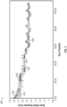
- FIG. 4 is a graph 400 of beam waist diameter versus time, in accordance with an embodiment.
- Graph 400 represents data taken from a UV beam while directing a 532 nm source beam along path 300 in FIG. 3A .
- the source beam had a fundamental wavelength of 532nm and power of 15W and was directed to a CLBO NLO crystal to produce a UV beam (SHG) of wavelength 266nm and power of 3W.
- the waist of the focused 532 nm source beam, located within the non-linear laser crystal had an elliptical cross section of 200 ⁇ m x 500 ⁇ m.
- the closed path length in embodiment 300 is 1000 ⁇ m and UV beam waist diameter (2 ⁇ 0 ) was measured for a plurality of shift speeds, 200 ⁇ m/hr (identified as 410 in graph 400), 60 ⁇ m/hr (identified as 420 in graph 400), and 20 ⁇ m/hr (identified as 430 in graph 400).
- the cycle time for these speeds was 300 min, 1000 min, and 3000 min respectively.
- the beam inside a non-linear crystal is typically a focused beam; the beam is focused to achieve the required intensity for non-linear conversion.
- an input beam is focused into a non-linear crystal by a lens and an output beam is collimated by another lens.
- the beam waist diameter on the y-axis is a collimated output beam waist diameter.
- Graph 400 plots the measurements of UV beam waist diameter against the run time for the plurality of shift speeds. Unexpectedly, the inventors discovered that varying shift speed affected certain beam parameters. As can be seen in Graph 400: at 200 ⁇ m/hr (identified as 410 in graph 400) the beam waist diameter is approximately 1.65 mm; at 60 ⁇ m/hr (identified as 420 in graph 400) the beam waist diameter drops to approximately 1.55 mm; and at 20 ⁇ m/hr (identified as 430 in graph 400) the beam waist diameter drops further to approximately 1.45 mm.
- shifting speeds can affect beam parameters and thus a non-linear crystal's shifting speed can be utilized to control beam parameters.
- a shifting speed can be changed to steer the beam parameter toward a target value.
- the target value is a range and, for example, as a beam parameter degrades below a setpoint (e.g., a lower threshold of the range), the shifting speed can be decelerated to raise the beam parameter above the setpoint.
- the shifting speed can be accelerated to raise the beam parameter above the setpoint.
- shifts can solely control the beam parameter or can be used in conjunction with active optics that adjust the beam parameter.
- shift speed can be used to stabilize the beam parameter within a feedback loop with the shifting speed as the actuating parameter to steer the actual beam parameter toward a target value.
- a target range is a percentage deviation from a target value.
- a target beam waist diameter and percentage deviation might be pre-set; a measured beam waist diameter that is greater than or less than the target beam waist diameter by the percentage deviation causes an adjustment in the shift speed.
- a measured beam waist diameter that is within the target beam waist diameter by the percentage deviation does not cause an adjustment in shift speed.
- the percentage is preferably 10%, more preferably 5%, and most preferably 1%.
- a small initial drift occurs after the source beam first begins to irradiate the non-linear crystal.
- the shifting speed can initially be relatively slow until the parameter settles to a stable level.
- a relatively slow speed may advantageously reduce the difference between the initial beam parameter measurement and the stable beam parameter measurement.
- a laser control unit may shift speed to achieve the desired target value. This may have the result that the shift speed starts at a first speed, the speed is increased as the beam stabilizes after an initial drift, and then the speed is changed (increased or decreased) as to steer the beam toward a target value.
- Graph 400 depicts noise in the measurement of the beam waist diameter.
- the noise may represent the active control of the shifting speed, up and down as the servo vacillates around the target beam waist diameter.
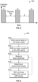
- FIG. 5 is a graph 500 of irradiation versus time, in accordance with an embodiment.
- Graph 500 depicts an irradiation time (t1) and a recovery time (t2) between irradiations.
- graph 500 may depict the irradiation time and recovery time of a single spot on path 300 in FIG. 3A
- FIG. 6 is a flow chart of an embodiment of a method 600 for controlling a UV beam.
- Method 600 includes directing a source beam to a non-linear crystal to produce a UV beam 602, shifting the non-linear crystal relative to the source beam at a first shift speed 604, measuring a beam parameter of the UV beam 606, determining, based on the measured beam parameter, a second shift speed that steers the beam parameter toward a target value 608; and shifting the non-linear crystal relative to the source beam at the second shift speed 610.
- steps 606-610 are optionally repeated (as indicated by the dashed arrow in Figure 6 ).
- the non-linear crystal degrades during an exposure to the source beam and at least partially recovers after the exposure to the source beam.
- shifting the non-linear crystal comprises shifting the non-linear crystal so that the source beam repeatedly traverses a path on the non-linear crystal, wherein a time between irradiations of a spot on the path is preferably at least 20 times longer than an irradiation time of the spot.
- the method includes determining whether the measured beam parameter is above the value and, in response to determining the measured beam parameter is above the value, determining a second shift speed faster than the first shift speed.
- the method includes determining whether the measured beam parameter is below the value and, in response to determining the measured beam parameter is below the value, determining a second shift speed slower than the first shift speed.
- the target value of the beam parameter comprises a target range of the beam parameter with an upper threshold and a lower threshold.
- the method may further comprise determining whether the measured beam parameter is above the upper threshold, and in response to determining the measured beam parameter is above the upper threshold, determining a second shift speed faster than the first shift speed.
- the method may further comprise determining whether the measured beam parameter is below the lower threshold, and, in response to determining the measured beam parameter is below the lower threshold, determining a second shift speed slower than the first shift speed.
- shifting the non-linear crystal comprises shifting the non-linear crystal so that the source beam traverses multiple serpentine paths on the non-linear crystal.
- shifting the non-linear crystal comprises shifting the non-linear crystal so that the source beam traverses a limited, smaller area on the crystal. In some embodiments, shifting the non-linear crystal comprises shifting multiple non-linear crystals.
- measuring the beam parameter comprises measuring the UV beam continuously.
- the method further includes continuously determining, based on the continuous measurements, additional shift speeds that steer the beam parameter toward the target value, and shifting the non-linear crystal relative to the source beam at the additional shift speeds.
- shifting the non-linear crystal comprises shifting the non-linear crystal so that the source beam repeatedly traverses a path on the non-linear crystal, and wherein the shift speed is adjusted at least once while traversing the complete path. For example, once during each completion of the path.
- the beam parameter is measured and the speed is adjusted at a refurbishment interval.
- the beam parameter is one of beam quality, axial beam waist location, beam divergence, and beam waist diameter.
- measuring the beam parameter of the UV beam comprises measuring a process property resulting from the UV beam's interaction with a process object.
Landscapes
- Physics & Mathematics (AREA)
- Nonlinear Science (AREA)
- Optics & Photonics (AREA)
- Electromagnetism (AREA)
- General Physics & Mathematics (AREA)
- Engineering & Computer Science (AREA)
- Plasma & Fusion (AREA)
- Spectroscopy & Molecular Physics (AREA)
- Life Sciences & Earth Sciences (AREA)
- Chemical & Material Sciences (AREA)
- Analytical Chemistry (AREA)
- Biochemistry (AREA)
- General Health & Medical Sciences (AREA)
- Immunology (AREA)
- Pathology (AREA)
- Health & Medical Sciences (AREA)
- Optical Modulation, Optical Deflection, Nonlinear Optics, Optical Demodulation, Optical Logic Elements (AREA)
Claims (23)
- UV-Laservorrichtung (100), umfassend:einen nichtlinearen Kristall (104);eine Laserquelle (102), die zum Richten eines Quellenstrahls (1021) auf den nichtlinearen Kristall (104), um einen UV-Strahl (1041) zu erzeugen, konfiguriert ist;einen Strahlkristallverlagerer (106), der zum Verschieben des nichtlinearen Kristalls (104) relativ zu dem Quellenstrahl (1021) mit einer Vielzahl von Verschiebegeschwindigkeiten konfiguriert ist;einen Strahlparametermonitor (108), der zum Messen des UV-Strahls (1041) konfiguriert ist, wobei der Strahlparametermonitor eine Linse, eine Apertur und eine Fotodiode beinhaltet, wobei die Linse zum Fokussieren des Strahls konfiguriert ist, um eine Strahlkaustik zu bilden, und die Apertur entlang der Strahlkaustik liegt, zum Beispiel an einer Stelle der Strahltaille, wobei die Fotodiode von einem ausgewählten Teil des Strahls belichtet wird, nachdem er durch die Linse und die Apertur hindurchgegangen ist, wobei der Ausgang der Fotodiode Änderungen misst, die mit einer Strahlparameteränderung korrelieren; undeine Lasersteuereinheit (110), die konfiguriert ist zum
Empfangen der Messung,Bestimmen, auf Basis der Messung, einer Einstellung der Verschiebegeschwindigkeit, um den überwachten Parameter in Richtung auf einen Zielwert zu lenken;und Ausgeben der Einstellung an den Strahlkristallverlagerer (106). - Vorrichtung nach Anspruch 1, wobei der Strahlmonitor ferner einen im Strahlengang liegenden Diffusor enthält.
- Vorrichtung nach Anspruch 1, wobei der nichtlineare Kristall (104) während einer Belichtung mit dem Quellenstrahl (1021) beeinträchtigt wird und sich nach der Belichtung mit dem Quellenstrahl (1021) zumindest teilweise erholt.
- Vorrichtung nach Anspruch 1, wobei der Strahlkristallverlagerer (106) zum Verschieben des nichtlinearen Kristalls (104, 302, 322, 342), so dass der Quellenstrahl (1021) wiederholt einen Pfad (300, 320, 340) durchläuft, konfiguriert ist; und
wobei eine Zeit zwischen Bestrahlungen eines Flecks (304, 324) auf dem Pfad (300, 320, 340) mindestens 20-mal länger ist als eine Bestrahlungszeit des Flecks (304, 324). - Vorrichtung nach Anspruch 1, wobei der Strahlkristallverlagerer (106) zum Verschieben des nichtlinearen Kristalls (104, 342), so dass der Quellenstrahl (1021) einen gewundenen Pfad (340) durchläuft, konfiguriert ist.
- Vorrichtung nach Anspruch 1, wobei die Lasersteuereinheit (110) ferner zum Ausgeben, bei Empfangen einer Messung, die über dem Zielwert liegt, einer Erhöhung der Verschiebegeschwindigkeit an den Strahlkristallverlagerer (106) konfiguriert ist und ferner zum Ausgeben, bei Empfangen einer Messung, die unter dem Zielwert liegt, einer Verringerung der Verschiebegeschwindigkeit an den Strahlkristallverlagerer (106) konfiguriert ist.
- Vorrichtung nach Anspruch 1, wobei der Zielwert einen Zielbereich des Größen- oder Ausbreitungsparameters mit einem oberen Schwellenwert und einem unteren Schwellenwert aufweist; und
wobei die Lasersteuereinheit (110) ferner zum Ausgeben, bei Empfangen einer Messung, die anzeigt, dass der Größen- oder Ausbreitungsparameter über dem oberen Schwellenwert liegt, einer Erhöhung der Verschiebegeschwindigkeit an den Strahlkristallverlagerer (106) konfiguriert ist und ferner zum Ausgeben, bei Empfangen einer Messung, die unter dem unteren Schwellenwert liegt, einer Verringerung der Verschiebegeschwindigkeit an den Strahlkristallverlagerer (106) konfiguriert ist. - Vorrichtung nach Anspruch 1, wobei der Strahlparametermonitor (108) zum kontinuierlichen Messen des UV-Strahls (1041) konfiguriert ist; und
wobei die Lasersteuereinheit (110) zum kontinuierlichen Ausgeben der Einstellung an den Strahlkristallverlagerer (106) konfiguriert ist. - Vorrichtung nach Anspruch 1, wobei der Strahlkristallverlagerer (106) zum Verschieben des nichtlinearen Kristalls (104, 302, 322, 342), so dass der Quellenstrahl (1021) wiederholt einen Pfad (300, 320, 340) durchläuft, konfiguriert ist und wobei die Verschiebegeschwindigkeit mindestens einmal während des Durchlaufens des gesamten Pfads (300, 320, 340) eingestellt wird.
- Vorrichtung nach Anspruch 1, wobei der Strahlparametermonitor (108) zum Messen des UV-Strahls (104l) in einem Sanierungsintervall konfiguriert ist.
- Vorrichtung nach Anspruch 1, bei der der Strahlkristallverlagerer (106) zum Verschieben des nichtlinearen Kristalls (104) relativ zu dem Quellenstrahl (102l) durch eines von einem kontinuierlichen Verschieben, einem annähernd kontinuierlichen Verschieben oder einem schrittweisen Verschieben konfiguriert ist.
- Verfahren zum Steuern eines UV-Strahls (1041) unter Verwendung einer UV-Laservorrichtung nach Anspruch 1, das Verfahren umfassend:Richten eines Quellenstrahls (1021) auf einen nichtlinearen Kristall (104), um einen UV-Strahl (1041) zu erzeugen;Verschieben des nichtlinearen Kristalls (104) relativ zu dem Quellenstrahl (1021) mit einer ersten Verschiebegeschwindigkeiten;Messen des UV-Strahls (1041) unter Verwendung des Strahlparametermonitors durch Belichten der Fotodiode des Strahlparametermonitors mit einem ausgewählten Teil des Strahls, nachdem er durch die Linse und die Apertur des Strahlparametermonitors hindurchgegangen ist, wobei die Linse zum Fokussieren des Strahls konfiguriert ist, um eine Strahlkaustik zu bilden, und die Apertur entlang der Strahlkaustik liegt, zum Beispiel an einer Stelle der Strahltaille, und der Ausgang der Fotodiode des Strahlparametermonitors Änderungen misst, die mit einer Strahlparameteränderung korrelieren; undBestimmen, auf Basis des gemessenen Parameters, einer zweiten Verschiebegeschwindigkeit, die den Parameter in Richtung auf einen Zielwert des Parameters lenkt; undVerschieben des nichtlinearen Kristalls (104) relativ zu dem Quellenstrahl (1021) mit der zweiten Verschiebegeschwindigkeit.
- Verfahren nach Anspruch 12, wobei der Strahlmonitor ferner einen im Strahlengang liegenden Diffusor enthält, der Strahl dabei von der Apertur zum Diffusor läuft und die Photodiode mit dem gestreuten Strahl belichtet.
- Verfahren nach Anspruch 12, wobei der nichtlineare Kristall (104) während einer Belichtung mit dem Quellenstrahl (1021) beeinträchtigt wird und sich nach der Belichtung mit dem Quellenstrahl (1021) zumindest teilweise erholt.
- Verfahren nach Anspruch 12, wobei das Verschieben des nichtlinearen Kristalls (104, 302, 322, 342) das Verschieben des nichtlinearen Kristalls, so dass der Quellenstrahl (1021) wiederholt einen Pfad (300, 320, 340) auf dem nichtlinearen Kristall (104, 302, 322, 342) durchläuft, umfasst; und
wobei eine Zeit zwischen Bestrahlungen eines Flecks (304, 324) auf dem Pfad (300, 320, 340) mindestens 20-mal länger ist als eine Bestrahlungszeit des Flecks (304, 324). - Verfahren nach Anspruch 12, wobei das Verschieben des nichtlinearen Kristalls (104, 302, 322, 342) das Verschieben des nichtlinearen Kristalls (104, 302, 322, 342), so dass der Quellenstrahl (1021) einen gewundenen Pfad (340) auf dem nichtlinearen Kristall (104, 302, 322, 342) durchläuft, umfasst.
- Verfahren nach Anspruch 12, ferner umfassend:Bestimmen, ob der gemessene Parameter über dem Zielwert liegt; undals Reaktion auf das Bestimmen, dass der gemessene Parameter über dem Zielwert liegt, Bestimmen der zweiten Verschiebegeschwindigkeit, wobei die zweite Verschiebegeschwindigkeit schneller als die erste Verschiebegeschwindigkeit ist.
- Verfahren nach Anspruch 12, ferner umfassend:Bestimmen, ob der gemessene Parameter unter dem Zielwert liegt; undals Reaktion auf das Bestimmen, dass der gemessene Parameter unter dem Zielwert liegt, Bestimmen der zweiten Verschiebegeschwindigkeit, wobei die zweite Verschiebegeschwindigkeit langsamer als die erste Verschiebegeschwindigkeit ist.
- Verfahren nach Anspruch 12, wobei der Zielwert einen Zielbereich mit einem oberen Schwellenwert und einem unteren Schwellenwert umfasst;
das Verfahren ferner umfassend:Bestimmen, ob der gemessene Parameter über dem oberen Schwellenwert liegt;als Reaktion auf das Bestimmen, dass der gemessene Parameter über dem oberen Schwellenwert liegt, Bestimmen der zweiten Verschiebegeschwindigkeit, wobei die zweite Verschiebegeschwindigkeit schneller als die erste Verschiebegeschwindigkeit ist; oderBestimmen, ob der gemessene Parameter unter dem unteren Schwellenwert liegt; undals Reaktion auf das Bestimmen, dass der gemessene Parameter unter dem unteren Schwellenwert liegt, Bestimmen der zweiten Verschiebegeschwindigkeit, wobei die zweite Verschiebegeschwindigkeit langsamer als die erste Verschiebegeschwindigkeit ist. - Verfahren nach Anspruch 12, wobei der Messschritt kontinuierliches Messen des UV-Strahls (1041) umfasst;
das Verfahren ferner umfassend:kontinuierliches Bestimmen, auf Basis der kontinuierlichen Messungen, von zusätzlichen Verschiebegeschwindigkeiten, die den gemessenen Parameter in Richtung auf den Zielwert lenken; undVerschieben des nichtlinearen Kristalls (104) relativ zu dem Quellenstrahl (1021) mit den zusätzlichen Verschiebegeschwindigkeiten. - Verfahren nach Anspruch 12, wobei das Verschieben des nichtlinearen Kristalls (104, 302, 322, 342) das Verschieben des nichtlinearen Kristalls (104, 302, 322, 342), so dass der Quellenstrahl (1021) wiederholt einen Pfad (300, 320, 340) auf dem nichtlinearen Kristall (104, 302, 322, 342) durchläuft, umfasst und wobei das Verschieben mit der zweiten Verschiebegeschwindigkeit das Verschieben mit der zweiten Verschiebegeschwindigkeit mindestens einmal während des Durchlaufens des gesamten Pfads (300, 320, 340) umfasst.
- Verfahren nach Anspruch 12, wobei der Messschritt das Messen des UV-Strahls (1041) in einem Sanierungsintervall umfasst.
- Verfahren nach Anspruch 12, wobei das Verschieben des nichtlinearen Kristalls (104) relativ zu dem Quellenstrahl (102l) das Verschieben des nichtlinearen Kristalls (104) relativ zu dem Quellenstrahl (1021) durch eines von einem kontinuierlichen Verschieben, einem annähernd kontinuierlichen Verschieben oder einem schrittweisen Verschieben umfasst.
Applications Claiming Priority (2)
| Application Number | Priority Date | Filing Date | Title |
|---|---|---|---|
| US15/926,178 US10312659B1 (en) | 2018-03-20 | 2018-03-20 | Controlling laser beam parameters by crystal shifting |
| PCT/EP2019/056728 WO2019179954A1 (en) | 2018-03-20 | 2019-03-18 | Controlling laser beam parameters by crystal shifting |
Publications (3)
| Publication Number | Publication Date |
|---|---|
| EP3769381A1 EP3769381A1 (de) | 2021-01-27 |
| EP3769381B1 true EP3769381B1 (de) | 2025-01-01 |
| EP3769381C0 EP3769381C0 (de) | 2025-01-01 |
Family
ID=65894993
Family Applications (1)
| Application Number | Title | Priority Date | Filing Date |
|---|---|---|---|
| EP19712732.7A Active EP3769381B1 (de) | 2018-03-20 | 2019-03-18 | Steuerung von laserstrahlparametern durch kristallverschiebung |
Country Status (5)
| Country | Link |
|---|---|
| US (1) | US10312659B1 (de) |
| EP (1) | EP3769381B1 (de) |
| JP (1) | JP2021518578A (de) |
| CN (1) | CN113169500A (de) |
| WO (1) | WO2019179954A1 (de) |
Families Citing this family (3)
| Publication number | Priority date | Publication date | Assignee | Title |
|---|---|---|---|---|
| US11619860B1 (en) | 2021-09-27 | 2023-04-04 | Coherent Lasersystems Gmbh & Co. Kg | Cantilever device for shifting optically nonlinear crystal |
| CN115254797A (zh) * | 2022-05-13 | 2022-11-01 | 武汉锐科光纤激光技术股份有限公司 | 附着材料的清洗方法和装置、存储介质及电子装置 |
| EP4683784A1 (de) | 2023-03-22 | 2026-01-28 | Carbon, Inc. | Verfahren und vorrichtung zur generativen und subtraktiven fertigung von lichtpolymerisierbaren harzen |
Family Cites Families (21)
| Publication number | Priority date | Publication date | Assignee | Title |
|---|---|---|---|---|
| US5214485A (en) | 1989-04-27 | 1993-05-25 | Coherent, Inc. | Apparatus for measuring the mode quality of a laser beam |
| US5064284A (en) | 1990-04-26 | 1991-11-12 | Coherent, Inc. | Apparatus for measuring the mode quality of a laser beam |
| US5825562A (en) | 1997-08-18 | 1998-10-20 | Novatec Corporation | Method of continuous motion for prolong usage of optical elements under the irradiation of intensive laser beams |
| US6765201B2 (en) * | 2000-02-09 | 2004-07-20 | Hitachi, Ltd. | Ultraviolet laser-generating device and defect inspection apparatus and method therefor |
| JP4474756B2 (ja) * | 2000-08-17 | 2010-06-09 | ソニー株式会社 | レーザ光発生装置 |
| EP1386196A1 (de) | 2001-05-08 | 2004-02-04 | Spectra Physics Lasers, Inc. | Algorithmus zur verbesserung der lebensdauer von kritischen komponenten in einem lasersystem |
| JP2003057696A (ja) * | 2001-08-20 | 2003-02-26 | Sumitomo Heavy Ind Ltd | レーザ波長変換方法、レーザ光源及びそれを用いたレーザ加工装置 |
| US6816316B2 (en) * | 2002-02-12 | 2004-11-09 | Visx, Incorporated | Smoothing laser beam integration using optical element motion |
| US6859335B1 (en) | 2002-11-20 | 2005-02-22 | Ming Lai | Method of programmed displacement for prolong usage of optical elements under the irradiation of intensive laser beams |
| DE20306411U1 (de) * | 2003-04-24 | 2003-07-03 | Trumpf Laser Marking Systems AG, Grüsch | Anordnung eines optischen Elements im Strahlengang eines Laserstrahls |
| US7366214B2 (en) * | 2004-09-14 | 2008-04-29 | B & W Property Inc. | Diode-pumped solid-state laser with self-maintained multi-dimensional optimization |
| JP2006317724A (ja) * | 2005-05-13 | 2006-11-24 | Nikon Corp | 波長変換光学系及びレーザ装置 |
| CN100511881C (zh) * | 2006-07-08 | 2009-07-08 | 深圳市大族激光科技股份有限公司 | 四次谐波固体激光器 |
| CN101197488A (zh) * | 2006-12-04 | 2008-06-11 | 深圳市大族激光科技股份有限公司 | 四次谐波紫外激光器 |
| JP4561892B2 (ja) * | 2008-07-11 | 2010-10-13 | ソニー株式会社 | 波長変換装置、レーザ光発生装置および波長変換方法 |
| JP4729093B2 (ja) * | 2008-11-27 | 2011-07-20 | 株式会社東芝 | 波長変換光源装置及び波長変換方法 |
| JP4608663B2 (ja) * | 2009-05-07 | 2011-01-12 | 株式会社東芝 | レーザ光源運用方法 |
| US8482846B2 (en) | 2010-08-09 | 2013-07-09 | Coherent Gmbh | Advanced shifting algorithm for prolonging the life of an optically nonlinear crystal |
| US8976343B2 (en) | 2012-06-21 | 2015-03-10 | Kla-Tencor Corporation | Laser crystal degradation compensation |
| EP2905643B1 (de) * | 2014-02-05 | 2019-07-03 | TRUMPF Schweiz AG | Verfahreinrichtung für einen nichtlinearen Kristall oder für sättigbare Absorber und Verfahren zum Ermitteln der Schrittweite der Verfahreinrichtung |
| DE102014218353B4 (de) * | 2014-09-12 | 2020-03-12 | Crylas Crystal Laser Systems Gmbh | Laseranordnung und Verfahren zur Erhöhung der Lebensdaueroptischer Elemente in einer Laseranordnung |
-
2018
- 2018-03-20 US US15/926,178 patent/US10312659B1/en active Active
-
2019
- 2019-03-18 JP JP2020550100A patent/JP2021518578A/ja active Pending
- 2019-03-18 WO PCT/EP2019/056728 patent/WO2019179954A1/en not_active Ceased
- 2019-03-18 CN CN201980020855.1A patent/CN113169500A/zh active Pending
- 2019-03-18 EP EP19712732.7A patent/EP3769381B1/de active Active
Also Published As
| Publication number | Publication date |
|---|---|
| WO2019179954A1 (en) | 2019-09-26 |
| US10312659B1 (en) | 2019-06-04 |
| EP3769381A1 (de) | 2021-01-27 |
| EP3769381C0 (de) | 2025-01-01 |
| CN113169500A (zh) | 2021-07-23 |
| JP2021518578A (ja) | 2021-08-02 |
Similar Documents
| Publication | Publication Date | Title |
|---|---|---|
| US9089927B2 (en) | Laser pulse generation method and apparatus | |
| JP4565207B1 (ja) | 波長変換装置及び波長変換方法並びに半導体装置の製造方法 | |
| US20080023452A1 (en) | CO2 laser stabilization systems and methods | |
| JP4935736B2 (ja) | 光記録方法及び光記録装置 | |
| US10312659B1 (en) | Controlling laser beam parameters by crystal shifting | |
| WO2003049239A2 (en) | Solid state system and method for generating ultraviolet light | |
| TWI761081B (zh) | 波長變換雷射裝置及波長變換雷射加工機 | |
| JP2003272892A (ja) | X線発生方法およびx線発生装置 | |
| JP2011014685A (ja) | レーザ照射装置、及びレーザ照射方法 | |
| TWI756229B (zh) | 波長變換裝置 | |
| JP2008055456A (ja) | 半田付け方法および半田付け用レーザ装置 | |
| JP2001042372A (ja) | 加工用レーザ装置 | |
| JP4532378B2 (ja) | レーザ光源運用方法 | |
| JP4608663B2 (ja) | レーザ光源運用方法 | |
| JP3968868B2 (ja) | 固体レーザ装置 | |
| JP7079953B2 (ja) | 波長変換方法、波長変換装置及びレーザ光源装置 | |
| JP3506038B2 (ja) | 波長変換方法 | |
| JP5026186B2 (ja) | 光学材料のレーザ損傷耐性推定方法及びレーザ損傷耐性推定装置 | |
| JP2013007931A (ja) | レーザ装置、露光装置及び検査装置 | |
| JP7672594B1 (ja) | レーザ装置およびレーザ加工装置 | |
| RU2824023C1 (ru) | Система стабилизации мощности лазерного излучения и способ ее применения | |
| Mielke et al. | Pulse width stabilization for ultrafast laser systems | |
| JP3916734B2 (ja) | レーザ加工装置 | |
| TWI746692B (zh) | 雷射裝置 | |
| JP2019072736A (ja) | レーザ加工装置及びレーザ加工方法 |
Legal Events
| Date | Code | Title | Description |
|---|---|---|---|
| STAA | Information on the status of an ep patent application or granted ep patent |
Free format text: STATUS: UNKNOWN |
|
| STAA | Information on the status of an ep patent application or granted ep patent |
Free format text: STATUS: THE INTERNATIONAL PUBLICATION HAS BEEN MADE |
|
| PUAI | Public reference made under article 153(3) epc to a published international application that has entered the european phase |
Free format text: ORIGINAL CODE: 0009012 |
|
| STAA | Information on the status of an ep patent application or granted ep patent |
Free format text: STATUS: REQUEST FOR EXAMINATION WAS MADE |
|
| 17P | Request for examination filed |
Effective date: 20200908 |
|
| AK | Designated contracting states |
Kind code of ref document: A1 Designated state(s): AL AT BE BG CH CY CZ DE DK EE ES FI FR GB GR HR HU IE IS IT LI LT LU LV MC MK MT NL NO PL PT RO RS SE SI SK SM TR |
|
| AX | Request for extension of the european patent |
Extension state: BA ME |
|
| DAV | Request for validation of the european patent (deleted) | ||
| DAX | Request for extension of the european patent (deleted) | ||
| STAA | Information on the status of an ep patent application or granted ep patent |
Free format text: STATUS: EXAMINATION IS IN PROGRESS |
|
| 17Q | First examination report despatched |
Effective date: 20210723 |
|
| P01 | Opt-out of the competence of the unified patent court (upc) registered |
Effective date: 20230625 |
|
| GRAP | Despatch of communication of intention to grant a patent |
Free format text: ORIGINAL CODE: EPIDOSNIGR1 |
|
| STAA | Information on the status of an ep patent application or granted ep patent |
Free format text: STATUS: GRANT OF PATENT IS INTENDED |
|
| RIC1 | Information provided on ipc code assigned before grant |
Ipc: G01N 21/956 20060101ALN20240222BHEP Ipc: G01N 21/95 20060101ALN20240222BHEP Ipc: G01N 21/88 20060101ALI20240222BHEP Ipc: G01J 1/42 20060101ALI20240222BHEP Ipc: G02F 1/35 20060101ALI20240222BHEP Ipc: H01S 3/00 20060101AFI20240222BHEP |
|
| RIC1 | Information provided on ipc code assigned before grant |
Ipc: G01N 21/956 20060101ALN20240305BHEP Ipc: G01N 21/95 20060101ALN20240305BHEP Ipc: G01N 21/88 20060101ALI20240305BHEP Ipc: G01J 1/42 20060101ALI20240305BHEP Ipc: G02F 1/35 20060101ALI20240305BHEP Ipc: H01S 3/00 20060101AFI20240305BHEP |
|
| INTG | Intention to grant announced |
Effective date: 20240322 |
|
| GRAJ | Information related to disapproval of communication of intention to grant by the applicant or resumption of examination proceedings by the epo deleted |
Free format text: ORIGINAL CODE: EPIDOSDIGR1 |
|
| STAA | Information on the status of an ep patent application or granted ep patent |
Free format text: STATUS: EXAMINATION IS IN PROGRESS |
|
| GRAP | Despatch of communication of intention to grant a patent |
Free format text: ORIGINAL CODE: EPIDOSNIGR1 |
|
| STAA | Information on the status of an ep patent application or granted ep patent |
Free format text: STATUS: GRANT OF PATENT IS INTENDED |
|
| INTC | Intention to grant announced (deleted) | ||
| RIC1 | Information provided on ipc code assigned before grant |
Ipc: G01N 21/956 20060101ALN20240710BHEP Ipc: G01N 21/95 20060101ALN20240710BHEP Ipc: G01N 21/88 20060101ALI20240710BHEP Ipc: G01J 1/42 20060101ALI20240710BHEP Ipc: G02F 1/35 20060101ALI20240710BHEP Ipc: H01S 3/00 20060101AFI20240710BHEP |
|
| INTG | Intention to grant announced |
Effective date: 20240723 |
|
| GRAS | Grant fee paid |
Free format text: ORIGINAL CODE: EPIDOSNIGR3 |
|
| GRAA | (expected) grant |
Free format text: ORIGINAL CODE: 0009210 |
|
| STAA | Information on the status of an ep patent application or granted ep patent |
Free format text: STATUS: THE PATENT HAS BEEN GRANTED |
|
| AK | Designated contracting states |
Kind code of ref document: B1 Designated state(s): AL AT BE BG CH CY CZ DE DK EE ES FI FR GB GR HR HU IE IS IT LI LT LU LV MC MK MT NL NO PL PT RO RS SE SI SK SM TR |
|
| REG | Reference to a national code |
Ref country code: GB Ref legal event code: FG4D |
|
| REG | Reference to a national code |
Ref country code: CH Ref legal event code: EP |
|
| REG | Reference to a national code |
Ref country code: DE Ref legal event code: R096 Ref document number: 602019064226 Country of ref document: DE |
|
| REG | Reference to a national code |
Ref country code: IE Ref legal event code: FG4D |
|
| U01 | Request for unitary effect filed |
Effective date: 20250128 |
|
| U07 | Unitary effect registered |
Designated state(s): AT BE BG DE DK EE FI FR IT LT LU LV MT NL PT RO SE SI Effective date: 20250203 |
|
| P04 | Withdrawal of opt-out of the competence of the unified patent court (upc) registered |
Free format text: CASE NUMBER: APP_4972/2025 Effective date: 20250129 |
|
| U20 | Renewal fee for the european patent with unitary effect paid |
Year of fee payment: 7 Effective date: 20250205 |
|
| PG25 | Lapsed in a contracting state [announced via postgrant information from national office to epo] |
Ref country code: PL Free format text: LAPSE BECAUSE OF FAILURE TO SUBMIT A TRANSLATION OF THE DESCRIPTION OR TO PAY THE FEE WITHIN THE PRESCRIBED TIME-LIMIT Effective date: 20250101 |
|
| PG25 | Lapsed in a contracting state [announced via postgrant information from national office to epo] |
Ref country code: ES Free format text: LAPSE BECAUSE OF FAILURE TO SUBMIT A TRANSLATION OF THE DESCRIPTION OR TO PAY THE FEE WITHIN THE PRESCRIBED TIME-LIMIT Effective date: 20250101 |
|
| PG25 | Lapsed in a contracting state [announced via postgrant information from national office to epo] |
Ref country code: NO Free format text: LAPSE BECAUSE OF FAILURE TO SUBMIT A TRANSLATION OF THE DESCRIPTION OR TO PAY THE FEE WITHIN THE PRESCRIBED TIME-LIMIT Effective date: 20250401 Ref country code: IS Free format text: LAPSE BECAUSE OF FAILURE TO SUBMIT A TRANSLATION OF THE DESCRIPTION OR TO PAY THE FEE WITHIN THE PRESCRIBED TIME-LIMIT Effective date: 20250501 |
|
| PG25 | Lapsed in a contracting state [announced via postgrant information from national office to epo] |
Ref country code: HR Free format text: LAPSE BECAUSE OF FAILURE TO SUBMIT A TRANSLATION OF THE DESCRIPTION OR TO PAY THE FEE WITHIN THE PRESCRIBED TIME-LIMIT Effective date: 20250101 |
|
| PG25 | Lapsed in a contracting state [announced via postgrant information from national office to epo] |
Ref country code: GR Free format text: LAPSE BECAUSE OF FAILURE TO SUBMIT A TRANSLATION OF THE DESCRIPTION OR TO PAY THE FEE WITHIN THE PRESCRIBED TIME-LIMIT Effective date: 20250402 |
|
| PG25 | Lapsed in a contracting state [announced via postgrant information from national office to epo] |
Ref country code: CZ Free format text: LAPSE BECAUSE OF FAILURE TO SUBMIT A TRANSLATION OF THE DESCRIPTION OR TO PAY THE FEE WITHIN THE PRESCRIBED TIME-LIMIT Effective date: 20250101 |
|
| PG25 | Lapsed in a contracting state [announced via postgrant information from national office to epo] |
Ref country code: SM Free format text: LAPSE BECAUSE OF FAILURE TO SUBMIT A TRANSLATION OF THE DESCRIPTION OR TO PAY THE FEE WITHIN THE PRESCRIBED TIME-LIMIT Effective date: 20250101 |
|
| PG25 | Lapsed in a contracting state [announced via postgrant information from national office to epo] |
Ref country code: MC Free format text: LAPSE BECAUSE OF FAILURE TO SUBMIT A TRANSLATION OF THE DESCRIPTION OR TO PAY THE FEE WITHIN THE PRESCRIBED TIME-LIMIT Effective date: 20250101 |
|
| REG | Reference to a national code |
Ref country code: CH Ref legal event code: H13 Free format text: ST27 STATUS EVENT CODE: U-0-0-H10-H13 (AS PROVIDED BY THE NATIONAL OFFICE) Effective date: 20251023 |
|
| PG25 | Lapsed in a contracting state [announced via postgrant information from national office to epo] |
Ref country code: SK Free format text: LAPSE BECAUSE OF FAILURE TO SUBMIT A TRANSLATION OF THE DESCRIPTION OR TO PAY THE FEE WITHIN THE PRESCRIBED TIME-LIMIT Effective date: 20250101 |
|
| PLBE | No opposition filed within time limit |
Free format text: ORIGINAL CODE: 0009261 |
|
| STAA | Information on the status of an ep patent application or granted ep patent |
Free format text: STATUS: NO OPPOSITION FILED WITHIN TIME LIMIT |
|
| 26N | No opposition filed |
Effective date: 20251002 |
|
| GBPC | Gb: european patent ceased through non-payment of renewal fee |
Effective date: 20250401 |
|
| PG25 | Lapsed in a contracting state [announced via postgrant information from national office to epo] |
Ref country code: GB Free format text: LAPSE BECAUSE OF NON-PAYMENT OF DUE FEES Effective date: 20250401 |
|
| PG25 | Lapsed in a contracting state [announced via postgrant information from national office to epo] |
Ref country code: CH Free format text: LAPSE BECAUSE OF NON-PAYMENT OF DUE FEES Effective date: 20250331 |
|
| PG25 | Lapsed in a contracting state [announced via postgrant information from national office to epo] |
Ref country code: IE Free format text: LAPSE BECAUSE OF NON-PAYMENT OF DUE FEES Effective date: 20250318 |
|
| U20 | Renewal fee for the european patent with unitary effect paid |
Year of fee payment: 8 Effective date: 20260209 |