EP3769019B1 - Antriebsanordnung - Google Patents
Antriebsanordnung Download PDFInfo
- Publication number
- EP3769019B1 EP3769019B1 EP19711839.1A EP19711839A EP3769019B1 EP 3769019 B1 EP3769019 B1 EP 3769019B1 EP 19711839 A EP19711839 A EP 19711839A EP 3769019 B1 EP3769019 B1 EP 3769019B1
- Authority
- EP
- European Patent Office
- Prior art keywords
- drive
- section
- recess
- cross
- holding
- Prior art date
- Legal status (The legal status is an assumption and is not a legal conclusion. Google has not performed a legal analysis and makes no representation as to the accuracy of the status listed.)
- Active
Links
Images


Classifications
-
- H—ELECTRICITY
- H02—GENERATION; CONVERSION OR DISTRIBUTION OF ELECTRIC POWER
- H02S—GENERATION OF ELECTRIC POWER BY CONVERSION OF INFRARED RADIATION, VISIBLE LIGHT OR ULTRAVIOLET LIGHT, e.g. USING PHOTOVOLTAIC [PV] MODULES
- H02S20/00—Supporting structures for PV modules
- H02S20/30—Supporting structures being movable or adjustable, e.g. for angle adjustment
- H02S20/32—Supporting structures being movable or adjustable, e.g. for angle adjustment specially adapted for solar tracking
-
- F—MECHANICAL ENGINEERING; LIGHTING; HEATING; WEAPONS; BLASTING
- F24—HEATING; RANGES; VENTILATING
- F24S—SOLAR HEAT COLLECTORS; SOLAR HEAT SYSTEMS
- F24S25/00—Arrangement of stationary mountings or supports for solar heat collector modules
- F24S25/10—Arrangement of stationary mountings or supports for solar heat collector modules extending in directions away from a supporting surface
- F24S25/12—Arrangement of stationary mountings or supports for solar heat collector modules extending in directions away from a supporting surface using posts in combination with upper profiles
-
- F—MECHANICAL ENGINEERING; LIGHTING; HEATING; WEAPONS; BLASTING
- F24—HEATING; RANGES; VENTILATING
- F24S—SOLAR HEAT COLLECTORS; SOLAR HEAT SYSTEMS
- F24S30/00—Arrangements for moving or orienting solar heat collector modules
- F24S30/40—Arrangements for moving or orienting solar heat collector modules for rotary movement
- F24S30/42—Arrangements for moving or orienting solar heat collector modules for rotary movement with only one rotation axis
- F24S30/425—Horizontal axis
-
- F—MECHANICAL ENGINEERING; LIGHTING; HEATING; WEAPONS; BLASTING
- F24—HEATING; RANGES; VENTILATING
- F24S—SOLAR HEAT COLLECTORS; SOLAR HEAT SYSTEMS
- F24S25/00—Arrangement of stationary mountings or supports for solar heat collector modules
- F24S2025/01—Special support components; Methods of use
- F24S2025/018—Means for preventing movements, e.g. stops
-
- F—MECHANICAL ENGINEERING; LIGHTING; HEATING; WEAPONS; BLASTING
- F24—HEATING; RANGES; VENTILATING
- F24S—SOLAR HEAT COLLECTORS; SOLAR HEAT SYSTEMS
- F24S30/00—Arrangements for moving or orienting solar heat collector modules
- F24S2030/10—Special components
- F24S2030/11—Driving means
-
- F—MECHANICAL ENGINEERING; LIGHTING; HEATING; WEAPONS; BLASTING
- F24—HEATING; RANGES; VENTILATING
- F24S—SOLAR HEAT COLLECTORS; SOLAR HEAT SYSTEMS
- F24S30/00—Arrangements for moving or orienting solar heat collector modules
- F24S2030/10—Special components
- F24S2030/13—Transmissions
- F24S2030/134—Transmissions in the form of gearings or rack-and-pinion transmissions
-
- F—MECHANICAL ENGINEERING; LIGHTING; HEATING; WEAPONS; BLASTING
- F24—HEATING; RANGES; VENTILATING
- F24S—SOLAR HEAT COLLECTORS; SOLAR HEAT SYSTEMS
- F24S30/00—Arrangements for moving or orienting solar heat collector modules
- F24S2030/10—Special components
- F24S2030/13—Transmissions
- F24S2030/136—Transmissions for moving several solar collectors by common transmission elements
-
- Y—GENERAL TAGGING OF NEW TECHNOLOGICAL DEVELOPMENTS; GENERAL TAGGING OF CROSS-SECTIONAL TECHNOLOGIES SPANNING OVER SEVERAL SECTIONS OF THE IPC; TECHNICAL SUBJECTS COVERED BY FORMER USPC CROSS-REFERENCE ART COLLECTIONS [XRACs] AND DIGESTS
- Y02—TECHNOLOGIES OR APPLICATIONS FOR MITIGATION OR ADAPTATION AGAINST CLIMATE CHANGE
- Y02E—REDUCTION OF GREENHOUSE GAS [GHG] EMISSIONS, RELATED TO ENERGY GENERATION, TRANSMISSION OR DISTRIBUTION
- Y02E10/00—Energy generation through renewable energy sources
- Y02E10/40—Solar thermal energy, e.g. solar towers
- Y02E10/47—Mountings or tracking
-
- Y—GENERAL TAGGING OF NEW TECHNOLOGICAL DEVELOPMENTS; GENERAL TAGGING OF CROSS-SECTIONAL TECHNOLOGIES SPANNING OVER SEVERAL SECTIONS OF THE IPC; TECHNICAL SUBJECTS COVERED BY FORMER USPC CROSS-REFERENCE ART COLLECTIONS [XRACs] AND DIGESTS
- Y02—TECHNOLOGIES OR APPLICATIONS FOR MITIGATION OR ADAPTATION AGAINST CLIMATE CHANGE
- Y02E—REDUCTION OF GREENHOUSE GAS [GHG] EMISSIONS, RELATED TO ENERGY GENERATION, TRANSMISSION OR DISTRIBUTION
- Y02E10/00—Energy generation through renewable energy sources
- Y02E10/50—Photovoltaic [PV] energy
Definitions
- the present invention relates to a drive arrangement for driving at least one output unit displaceable about a rotation or pivot axis.
- the document SU1305481 A1 discloses a drive arrangement with the features of the preamble of claim 1.
- the at least one drive element has a cross-section that deviates from a circular cross-section and is curved at least in sections and/or the at least one drive recess is in the radial direction. direction to define an inlet opening for the at least one drive element.
- the drive device and the output unit are designed in such a way that the function of the drive arrangement can be permanently guaranteed.
- the torque-transmitting engagement between the at least one drive recess and the at least one drive element can be ensured even if the distance between the drive device and the output unit increases due to manufacturing tolerances, assembly tolerances and/or elastic deformations of the drive device and/or the output unit.
- the functionality of the drive arrangement can also be maintained if the drive device and/or the drive unit are dirty.
- Such an increase in the distance, in particular the radial distance between the drive device and the output unit, can lead to a tangential displacement between the drive device and the output unit, which can impair or even prevent the engagement of the at least one drive element in the at least one drive recess.
- the invention can ensure the "threading" or engagement of the at least one drive element in the at least one drive recess even if the described increase in the radial distance or a tangential displacement between the drive device and the output unit occurs.
- the drive device and the output unit are coupled in such a way that torque is transmitted that when the drive device executes a rotary movement, a step-by-step rotary or adjusting movement of the output unit about its rotary or swivel axis can occur.
- a continuous rotary movement of the drive device about the rotary axis can accordingly lead to a step-by-step rotary or adjusting movement of the output unit.
- the rotary or adjusting movement of the output unit is always executed when the at least one drive element is in engagement with the at least one drive recess.
- the at least one drive element can engage in the associated drive recess of the output unit, take the output unit with it and then leave the drive recess again. Between the engagement of the drive element in the drive recess and the exit of the drive recess, the at least one drive element presses against a Wall of the drive recess, whereby a torque is exerted on the output unit, which leads to a rotational or adjusting movement of the output unit.
- the at least one holding element always engages in the at least one holding recess of the output unit when the at least one drive element is not in engagement with the at least one drive recess of the output unit.
- the at least one holding element can engage in the at least one holding recess in a form-fitting manner. In this state, the output unit can be held in its set position.
- the drive arrangement is thus in a locking position. In the locking position, rotation of the output unit about its axis of rotation or pivoting is prevented. Due to the rotational movement of the drive device with the at least one holding element, the at least one holding element initially engages with a section in the at least one associated holding recess of the output unit, this section continuously increasing due to the rotational movement of the drive device.
- the holding element can leave the at least one holding recess again. As soon as the at least one holding element engages even only partially in the holding recess, rotation of the output unit about its axis of rotation or pivoting can be prevented.
- the holding element and the drive element continue to rotate so that the drive element can be brought into engagement with the next drive recess.
- the drive element can be rotated by 90° to 270° about the axis of rotation of the drive arrangement after exiting a drive recess in order to engage with the next drive recess.
- the at least one holding element continues to rotate in the holding recess and leaves the holding recess when or shortly after the drive element engages in the next drive recess. The at least one holding element thus releases the output unit for the next adjustment step.
- the at least one drive element has a cross section with at least one curved section which contacts a wall of the at least one drive recess in order to drive the at least one output unit.
- the at least one drive element has a reduced cross section in the radial direction with respect to the axis of rotation of the drive device.
- the cross section of the at least one drive element can have at least a first vertex and at least a second vertex. The distance between the first vertex and the second vertex defines the greatest extent of the drive element.
- the cross section of the at least one drive element can have its greatest extent in a direction transverse to the radial direction of the drive device.
- the cross section of the at least one drive element can have at least a first edge and at least one second edge, the distance between which defines the greatest extent of the drive element. If two edges are provided on the cross section of the drive element, the cross section of the drive element has two curved sections which extend between the two edges.
- the cross section of the drive element has two vertices
- the cross section is also curved in the area of the vertices.
- the cross section of the drive element can therefore have several radii of curvature.
- the radius of curvature in the area of the vertices can differ from the radius of curvature of the section between the two vertices.
- the cross section of the at least one drive element has at least a third vertex and at least a fourth vertex.
- the distance between the third vertex and the fourth vertex is smaller than the distance between the first vertex or the first edge and the second vertex or the second edge.
- the third vertex and the fourth vertex can be aligned in the radial direction of the drive device.
- the distance between the first vertex and the second vertex can be matched to the size of the drive recess in order to achieve a guided movement of the at least one drive element in the drive recess when the output unit is displaced about its rotation or pivot axis.
- the distance between the third vertex and the fourth vertex which is smaller than the distance between the first vertex and the second vertex, makes it possible to compensate for tangential displacements between the drive device and the output unit, which can arise due to tolerances, so that the engagement of the at least one drive element in the associated drive recess can be ensured.
- the size of a radial A free space between the at least one holding element and the at least one drive element can be defined, which can support the alternating engagement of the drive element and the holding element in the associated drive recesses and holding recesses.
- the at least one drive recess can widen outwards in the radial direction in order to define an inlet opening for the at least one drive element. By widening the drive recess outwards in the radial direction, the inlet opening of the drive recess can be enlarged for the penetration or engagement of the drive element. The distance between two opposite flanks of the at least one drive recess can increase outwards in the radial direction. If the at least one drive recess is directed radially inwards, the at least one drive recess can widen inwards in the radial direction. This applies in particular if the drive device is arranged radially inside the output unit.
- the rotation axis of the drive device can run through or along the at least one holding element.
- the at least one holding element has a curved outer surface.
- the curvature of the outer surface of the holding element is matched to the curvature of the at least one holding recess, so that the at least one holding element can penetrate into the at least one holding recess and rotate in the holding recess.
- rotation of the output unit about its rotation or pivot axis can be prevented.
- the at least one holding element can have a curvature in at least one section that is matched to the curvature of the at least one holding recess.
- the radius of curvature of the curved section of the holding element can be matched to the radius of curvature of the wall of the at least one holding recess.
- the at least one drive element and the at least one holding element can be connected to one another via at least one connecting element.
- the connecting element can extend in the radial direction.
- the connecting element can be designed, for example, in the shape of a disc or cam.
- the at least one connecting element can also be connected to at least one coupling section, via which the at least one connecting element can be coupled to a drive.
- the coupling to the drive can take place directly or indirectly via further components.
- the at least one drive element and the at least one holding element can extend parallel to the axis of rotation of the drive device.
- the drive recesses and the holding recesses can be designed to correspond to the shape or cross section of the drive element and the holding element.
- the at least one drive element can have an oval or elliptical or lens-shaped cross section.
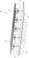
- FIG. 1 shows a perspective view of a tracking device for solar modules.
- the tracking device is generally designated NV.
- the tracking device NV has several swivel units 10 1 to 10 5.
- Each of the swivel units 10 1 to 10 5 is connected to a post 12 anchored in the ground U.
- the swivel units 10 1 to 10 5 are connected to one another via the drive shafts 14.
- the drive shafts 14 are driven by a motor M which is in Figure 1 is arranged on the swivel unit 10 5.
- the swivel units 10 1 to 10 5 are also connected to one another via support rails 16 and 18, to which solar modules 20 can be attached using fastening elements.
- the swivel units 10 1 to 10 5 are connected via the drive shafts 14, whereby the swivel units 10 1 to 10 5 can swivel the solar modules 20 attached thereto.
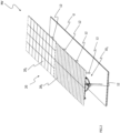
- FIG 2 shows a further perspective view of the tracking device NV, in which the solar modules 20 and the pivoting unit 10 5 arranged on a post 12 as well as the posts 12 of the further pivoting units 10 1 to 10 4 are shown.
- Solar modules 20 with different shapes, sizes, orientations and also solar modules 20 of different construction types can be attached to the tracking device NV, as in Figure 2 illustrated by the differently displayed solar modules 20 1 and 20 2 .
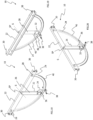
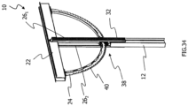
- the Figures 3 to 5 show various perspective views of a swivel unit 10 according to a first embodiment.
- the swivel unit 10 has a cross member 22, a drive arch 24 attached to the cross member 22 and a support element 26.
- the cross member 22 and the support element 26 are pivotably connected to one another.
- a pivot axis S extends through the cross member 22 and the support element 26.
- the pivot axis S extends through the pivot point SP formed at the connection point between the cross member 22 and the support element 26.
- the drive arch 24 is connected to the cross member 22 via fastening means 28 such as screws or bolts. Connecting elements 30 can be seen at the ends of the cross member 22.
- the cross member 22 can be connected to the Figure 1 shown support rails 16 and 18.
- the support element 26 can be connected with its end 32 opposite the pivot axis S to a post 12 anchored in or on the ground (see Figure 1 ).
- Fastening elements 34 and 36 are also attached to the end 32 of the carrier element 26.
- a drive device 38 is connected to the carrier element 26 via the fastening elements 34 and 36.
- the drive device 38 serves to pivot into a new pivot position and to hold the drive arch 24 in a set position. The pivoting of the drive arch can take place step by step.
- the drive device 38 is in engagement with a drive contour 40 on the drive arch 24.
- the drive contour 40 is formed on the outside of the drive arch 24 in the radial direction.
- the drive device 38 and the drive arch 24 form a drive arrangement.
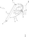
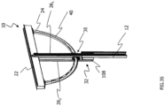
- FIGS 6 and 7 show two views of the swivel unit 10 from opposite directions.
- the cross member 22 the drive arch 24 and the support element 26 are shown.
- the support element 26 extends perpendicular to the cross member 22.
- the pivot point SP is formed in the middle of the cross member 22.
- the connecting elements 30 are shown, which are used to connect the cross member 22 to the support rails 16 and 18 (see Figure 1 ) serve.
- the fastening elements 34 and 36 are connected to the support element 26.
- the drive device 38 is rotatably mounted on the fastening elements 34 and 36.
- the fastening elements 34 and 36 hold the drive device 38 on the support element 26.
- the drive device 38 engages with the drive contour 40 on the drive arch 24.
- the drive contour 40 has two different types of recesses.
- the drive contour 40 has drive recesses 42 and holding recesses 44, which are arranged alternately in the direction of the circumference of the drive arch 24.
- the drive arch 24 and the cross member 22 connected thereto can be held in its set position.
- the drive device 38 can also change its position when engaged with one of the holding recesses 44 in order to be able to engage in the next drive recess 42. In this case, no torsional load is transferred to the drive shaft 14.
- the drive contour 40 and the drive device 38 will be discussed in more detail later in this description.
- Figure 8 shows a perspective exploded view of the swivel unit 10.
- the cross member 22, the drive arch 24, the support element 26, the drive device 38 and the two fastening elements 34 and 36 are shown.
- Figure 9 shows an enlarged view of the Figure 8 section marked IX.
- Figure 9 the end 32 of the support element 26, the two fastening elements 34 and 36 and a section of the drive arch 24 are shown.
- the fastening elements 34 and 36 each have two fastening sections 46 and 48.
- the fastening sections 46 and 48 are angled to the main body of the fastening elements 34 and 36.
- Each fastening section 46 and 48 has an opening 50, 52.
- the openings 50, 52 are in Figure 9 only recognizable by the fastening element 36. With these fastening sections 46 and 48, the fastening elements 34 and 36 are connected to the carrier element 26.
- the fastening elements 34 and 36 each have a bearing opening 54 and 56 in which the drive device 38 can be mounted.
- bearing bushes 58 and 60 are provided, which are received in the openings 54 and 56.
- the drive device 38 has two coupling elements 62 and 64.
- the coupling elements 62 and 64 are rod-shaped.
- the coupling elements 62 and 64 can be received in sections in the openings 54, 56 or in the bearing bushes 58, 60 arranged in the openings 54, 56.
- the coupling elements 62 and 64 each have a coupling section 66, 68 and a bearing section 70.
- the coupling sections 66 and 68 are provided with a cross-section which is suitable for coupling with a drive shaft 14 (see Figure 1 ) is suitable.
- the drive section 72 of the drive device 38 is formed between the coupling elements 62 and 64, in which the drive element 74 is provided.
- the drive element 74 engages in the drive contour 40 of the drive arch 24.
- a holding element is provided in the drive section 72, which in Figure 9 is not shown. The holding element will be discussed in detail later in this description.
- the swivel unit 10 has a guide element 76, which forms a guide device for radially guiding the drive arch 24.
- the drive arch 24 can be supported on the guide element 76 in the radial direction.
- the guide element 76 thus prevents the drive arch 24 from becoming disengaged from the drive device 38 in the radial direction.
- the guide element 76 is mounted on a spacer or bearing element 78.
- the bearing element 78 is arranged on a screw that extends between the fastening elements 34 and 36.
- the drive arch 24 runs between the two fastening elements 34 and 36.
- the fastening elements 34 and 36 are connected to one another via screws. In order to set and maintain a predetermined distance between the two fastening elements 34 and 36, the spacers 78 through which the screws extend are provided.
- Figure 10 shows a perspective exploded view of the swivel unit 10.
- the cross member 22, the drive arch 24, the support element 26, the drive device 38 and the two fastening elements 34 and 36 are shown.
- Figure 11 shows an enlarged view of the Figure 10 section marked XI.
- the drive device 38 which engages with the drive contour 40 of the drive arch 24, the fastening elements 34 and 36 and the end 32 of the carrier element 26 are shown.
- the drive device 38 has two coupling elements 62 and 64, which extend in opposite directions from the drive section 72.
- the bearing sections 70 of the coupling elements 62 and 64 adjoin the drive section 72 in the direction of the axis of rotation D.
- the bearing sections 70 are followed in the direction of the axis of rotation D by the coupling sections 66 and 68 with their cross-section designed for coupling to a drive shaft 14.
- the coupling elements 62 and 64 extend through the openings 54 and 56 and through the bearing bushes 58 and 60 arranged in the openings 54 and 56.
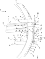
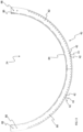
- the Figures 12 to 14 show different views of the drive arch 24.
- the drive arch 24 is made up of two partial arches 80 and 82, which are connected to an arcuate base element 84.
- the partial arches 80 and 82 can be welded to the base element 84, as can be seen from the weld seams 86 shown.
- Viewed in cross section, the drive arch 24 has a substantially T-shaped cross section through the base element 84. Starting from this base element 84, the partial arches 80, 82 extend in the radial direction.
- the partial arches 80, 82 each have two openings 88, via which the drive arch 24 can be connected to the cross member 22.
- the drive contour 40 has drive recesses 42 and holding recesses 44.
- the drive recesses 42 and the holding recesses 44 are arranged alternately in the circumferential direction of the drive arch 24.
- the drive recesses 42 are radial incisions in the drive arch 24.
- the drive recesses 42 can also be referred to as slot-shaped.
- the sections of the drive arch 24 formed between the drive recesses 42 or the incisions are provided with holding recesses 44.
- the holding recesses 44 are arched or curved.
- the holding recesses 44 are essentially semicircular.
- the Drive recesses 42 extend further in the radial direction into the drive arch 24 than the holding recesses 44.
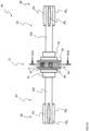
- Figure 15 shows a perspective view of the drive device 38.
- the drive device 38 is rotatable about the axis of rotation D, which corresponds to the longitudinal axis of the drive device 38.
- the drive device 38 has a drive section 72 and two coupling elements 62 and 64.
- the coupling elements 62 and 64 each have a bearing section 70 and a coupling section 66 and 68.
- the coupling sections 66 and 68 have a cross section which is suitable for coupling to a drive shaft 14 (see Figure 1 ). This cross section is formed by flattened portions 66 1 , 66 2 and 68 1 , 68 2 in the region of the coupling sections 66 and 68.
- the coupling sections 66 and 68 can be accommodated, for example, in a drive shaft 14 with a recess complementary to the cross section of the coupling sections 66 and 68.
- the coupling elements 62 and 64 extend in opposite directions.
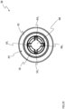
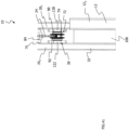
- Figure 16 shows a front view of the drive device 38.
- the bearing sections 70 of the coupling elements 62 and 64 have a circular cross-section. A step can be seen at the transition between the bearing sections 70 and the coupling sections 66 and 68 with their flattened areas 66 1 , 66 2 and 68 1 , 68 2 .
- the drive element 74 and the holding element 94 extend between the two connecting elements 90 and 92.
- the drive element 74 is arranged eccentrically.
- the drive element 74 extends offset in the radial direction parallel to the axis of rotation D.
- the holding element 94 has a semicircular outer contour, the outer surface of which in this embodiment extends on the same radius as the outer circumferential surfaces of the bearing sections 70 of the coupling elements 62 and 64 around the axis of rotation D of the drive device 38.
- Figure 17 shows a side view of the drive device 38, in which the coupling element 64, the connecting element 92 and the drive element 74 are shown.
- the connecting element 92 is cam-shaped.
- An opening 96 is formed in the connecting element 92, in which the drive element 74 is received.
- FIGS. 18 to 33 show a swivel unit 10 according to a second embodiment.
- the same reference numerals as in the first embodiment are used for similar or equivalent features or components. To avoid repetition, the differences between the two embodiments are described in detail below. Components and features that have already been described in detail with regard to the first embodiment will not be described in detail again. The description of these components and features also applies analogously to the second embodiment.
- the Figures 18 to 22 show various views of a swivel unit 10 according to the second embodiment.
- the swivel unit 10 has a cross member 22, a drive arch 24 attached to the cross member 22 and a support element 26.
- the drive arch 24 is connected to the cross member 22 via fastening means 28.
- Connecting elements 30 are attached to the ends of the cross member 22, via which the cross member 22 is connected to the support rails 16 and 18 ( Figure 1 ) can be connected.
- the support element 26 does not have a C-shaped cross section, unlike the first embodiment, but is rectangular in cross section.
- a pivot axis S extends through the pivot point SP formed at the connection point between the cross member 22 and the support element 26.
- the drive device 38 according to the second embodiment differs from the drive device of the first embodiment.
- the drive device 38 and in particular the differences from the The drive device according to the first embodiment will be discussed in detail in the further course of the description.
- Figure 23 shows a perspective exploded view of the swivel unit 10.
- the cross member 22, the drive arch 24, the support element 26, the drive device 38 and the two fastening elements 34 and 36 are shown.
- Figure 24 shows an enlarged view of the Figure 23 section marked XXIV.
- Figure 24 the end 32 of the support element 26, the two fastening elements 34 and 36 and a section of the drive arch 24 are shown.
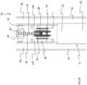
- Figure 26 shows an enlarged view of the Figure 25 section marked XXVI.
- the drive device 38 which engages with the drive contour 40 of the drive arch 24, the fastening elements 34 and 36 and the end 32 of the carrier element 26 are shown.
- the coupling sections 66 and 68 can be connected with their projections 66 1 , 66 2 , 66 3 , 66 4 and 68 1 , 68 2 , 68 3 , 68 4 to a drive shaft 14 (see Figure 1 ) to transmit torque.
- the coupling sections 66 and 68 and a section of the drive shaft 14 can be designed to be complementary.
- the coupling sections 66 and 68 and the corresponding section of a drive shaft 14 can be designed to be complementary so that they can be brought into engagement with one another.
- the coupling sections 66 and 68 and/or the section of the drive shaft 14 can be designed such that assembly-related distance tolerances between adjacent pivot units 10 or posts 12 arranged next to one another are compensated to a limited extent.
- the coupling elements 66 and 68 and the drive shaft can be designed such that, when engaged with one another, they allow a displacement relative to one another in the direction of the pivot axis in order to be able to compensate for the tolerances mentioned.
- the projections 66 1 , 66 2 , 66 3 and 68 1 , 68 2 , 68 3 have a curved radial outer surface 102 for this purpose.
- the outer surface 102 is curved in the direction of the axis of rotation D.
- the curvature is determined by the Figure 28 entered line LS 1 , which extends parallel to the axis of rotation D.
- the projections 66 1 , 66 2 , 66 3 and 68 1 , 68 2 , 68 3 have side surfaces 104 which are curved and extend in the radial direction.
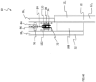
- Figure 36 shows an enlarged perspective view of the swivel unit 10, with the carrier element 26 1 hidden.
- the H-shaped cross section of the post 12 is clearly visible.
- the H-shaped cross section of the post 12 is made up of a cross leg 12 1 and two side legs 12 2 and 12 3 , which are connected to each other via the cross leg 12 1.
- a spacer 110 is located on both sides of the cross leg 12 1.
- the support element 26 1 (not shown) is connected to the post 12 via connecting elements 112 and 114.
- the cross leg 12 1 of the post 12 has several openings 116 which are in Figure 36 can be seen in outline above the spacer 110.
- the openings 116 are formed in an end section 12 4 of the post 12, which serves for connection to the pivot unit 10.
- the end section 12 4 forms a connecting section for connecting the post 12 to the support elements 26 1 and 26 2 .
Landscapes
- Engineering & Computer Science (AREA)
- Sustainable Development (AREA)
- Life Sciences & Earth Sciences (AREA)
- Chemical & Material Sciences (AREA)
- Sustainable Energy (AREA)
- Thermal Sciences (AREA)
- Physics & Mathematics (AREA)
- Combustion & Propulsion (AREA)
- Mechanical Engineering (AREA)
- General Engineering & Computer Science (AREA)
- Transmission Devices (AREA)
- Chairs For Special Purposes, Such As Reclining Chairs (AREA)
- Lens Barrels (AREA)
- Pivots And Pivotal Connections (AREA)
Priority Applications (3)
| Application Number | Priority Date | Filing Date | Title |
|---|---|---|---|
| RS20240876A RS65900B1 (sr) | 2018-03-23 | 2019-03-07 | Pogonski sklop |
| HRP20241114TT HRP20241114T1 (hr) | 2018-03-23 | 2019-03-07 | Pogonski sklop |
| SI201930801T SI3769019T1 (sl) | 2018-03-23 | 2019-03-07 | Razporeditev pogonov |
Applications Claiming Priority (2)
| Application Number | Priority Date | Filing Date | Title |
|---|---|---|---|
| DE102018002460.2A DE102018002460A1 (de) | 2018-03-23 | 2018-03-23 | Antriebsanordnung |
| PCT/EP2019/055690 WO2019179781A1 (de) | 2018-03-23 | 2019-03-07 | Antriebsanordnung |
Publications (2)
| Publication Number | Publication Date |
|---|---|
| EP3769019A1 EP3769019A1 (de) | 2021-01-27 |
| EP3769019B1 true EP3769019B1 (de) | 2024-07-10 |
Family
ID=65817971
Family Applications (1)
| Application Number | Title | Priority Date | Filing Date |
|---|---|---|---|
| EP19711839.1A Active EP3769019B1 (de) | 2018-03-23 | 2019-03-07 | Antriebsanordnung |
Country Status (15)
| Country | Link |
|---|---|
| US (1) | US11990860B2 (da) |
| EP (1) | EP3769019B1 (da) |
| CA (1) | CA3090979A1 (da) |
| DE (2) | DE102018002460A1 (da) |
| DK (1) | DK3769019T3 (da) |
| ES (1) | ES2984708T3 (da) |
| FI (1) | FI3769019T3 (da) |
| HR (1) | HRP20241114T1 (da) |
| HU (1) | HUE067958T2 (da) |
| LT (1) | LT3769019T (da) |
| PL (1) | PL3769019T3 (da) |
| PT (1) | PT3769019T (da) |
| RS (1) | RS65900B1 (da) |
| SI (1) | SI3769019T1 (da) |
| WO (1) | WO2019179781A1 (da) |
Families Citing this family (10)
| Publication number | Priority date | Publication date | Assignee | Title |
|---|---|---|---|---|
| PT3769018T (pt) * | 2018-03-23 | 2024-07-15 | Schletter Int B V | Unidade giratória para um sistema de seguimento destinado a módulos solares |
| DE202018103053U1 (de) * | 2018-05-30 | 2018-06-08 | Ideematec Deutschland Gmbh | Solaranlage mit verschwenkbarem und feststellbarem Modultisch |
| ES2957985B2 (es) * | 2020-04-21 | 2024-09-13 | Gamechange Solar Corp | Conjunto de rueda motriz de seguidor solar de un eje y conjunto de seguidor solar de un eje |
| US12003209B2 (en) * | 2021-05-19 | 2024-06-04 | Gamechange Solar Corp. | Pre-assembly based installation for a single axis solar tracker |
| FR3128599B1 (fr) | 2021-10-22 | 2023-10-13 | Nexans | Agencement d’entraînement de type croix de Malte et suiveur solaire comportant un tel agencement |
| WO2023114981A2 (en) | 2021-12-16 | 2023-06-22 | FTC Solar, Inc. | Solar tracker system including a frame assembly |
| DE102022102608B4 (de) * | 2022-02-03 | 2023-12-14 | Schletter International B.V. | Antriebsanordnung |
| DE102022102605A1 (de) * | 2022-02-03 | 2023-08-03 | Schletter International B.V. | Nachführeinrichtung für Solarmodule |
| WO2024178102A1 (en) * | 2023-02-21 | 2024-08-29 | Loven James F | Storm hardened solar racking system |
| EP4637025A1 (en) | 2024-04-16 | 2025-10-22 | CEP-IP Ltd | System for rotatably driving and locking panels |
Citations (1)
| Publication number | Priority date | Publication date | Assignee | Title |
|---|---|---|---|---|
| SU1305481A1 (ru) * | 1985-08-02 | 1987-04-23 | Андроповский авиационный технологический институт | Мальтийский механизм |
Family Cites Families (17)
| Publication number | Priority date | Publication date | Assignee | Title |
|---|---|---|---|---|
| US1198683A (en) | 1916-03-23 | 1916-09-19 | Alexander Ferdinand Victor | Mechanical movement. |
| DE328666C (de) * | 1917-06-14 | 1920-11-03 | Singer Mfg Co | Vorrichtung zur Umwandlung drehender Bewegung in schrittweise Bewegung |
| US2618187A (en) * | 1950-08-08 | 1952-11-18 | Keller Tool Co | Power-driven gear operated wrench |
| NL143086B (nl) | 1968-10-02 | 1974-08-15 | Smit Nijmegen Electrotec | Draaischakelaar met een aandrijfinrichting voor het met verschillende stappen verdraaien van het beweegbare schakelcontact van die schakelaar. |
| NL145333B (nl) | 1971-12-15 | 1975-03-17 | Smit Nijmegen Electrotec | Draaibare kiezer met een meervoudig maltezerkruis-drijfwerk. |
| US4224263A (en) | 1978-03-14 | 1980-09-23 | Owens-Illinois, Inc. | Method for blow molding |
| FR2437539A1 (fr) * | 1978-04-14 | 1980-04-25 | Romanet Fils Sarl | Dispositif d'entrainement d'une roue dentee par un moteur pas a pas |
| US4606235A (en) | 1983-09-29 | 1986-08-19 | Eastman Kodak Company | Geneva drive |
| US6183087B1 (en) | 1999-06-11 | 2001-02-06 | Eastman Kodak Company | Geneva mechanism and motion picture projector using same |
| US7526976B2 (en) * | 2006-09-14 | 2009-05-05 | Sun Ho-Wei | Control device for periodical driving system |
| BR112012029715A2 (pt) | 2010-05-28 | 2017-03-07 | Qbotix Inc | sistema para controlar múltiplas superfícies solares |
| DE102014209939A1 (de) * | 2014-05-26 | 2015-11-26 | Schaeffler Technologies AG & Co. KG | Getriebeanordnung mit Sperrfunktion |
| US20160365830A1 (en) | 2015-05-18 | 2016-12-15 | Alion Energy, Inc. | Systems and methods for rotating photovoltaic modules |
| BR112019000320B1 (pt) * | 2016-07-08 | 2023-12-26 | Alion Energy, Inc | Sistemas e métodos para montar e travar de maneira giratória painéis solares |
| WO2018009634A1 (en) * | 2016-07-08 | 2018-01-11 | Alion Energy, Inc. | Systems and methods for rotatably mounting and locking solar panels |
| US10174970B2 (en) * | 2016-09-09 | 2019-01-08 | Sunpower Corporation | Sun tracking solar energy collection system with torsion lock |
| DE202018103053U1 (de) | 2018-05-30 | 2018-06-08 | Ideematec Deutschland Gmbh | Solaranlage mit verschwenkbarem und feststellbarem Modultisch |
-
2018
- 2018-03-23 DE DE102018002460.2A patent/DE102018002460A1/de active Pending
-
2019
- 2019-03-07 HU HUE19711839A patent/HUE067958T2/hu unknown
- 2019-03-07 DK DK19711839.1T patent/DK3769019T3/da active
- 2019-03-07 DE DE202019006061.8U patent/DE202019006061U1/de active Active
- 2019-03-07 FI FIEP19711839.1T patent/FI3769019T3/fi active
- 2019-03-07 CA CA3090979A patent/CA3090979A1/en active Pending
- 2019-03-07 US US17/040,812 patent/US11990860B2/en active Active
- 2019-03-07 EP EP19711839.1A patent/EP3769019B1/de active Active
- 2019-03-07 LT LTEPPCT/EP2019/055690T patent/LT3769019T/lt unknown
- 2019-03-07 RS RS20240876A patent/RS65900B1/sr unknown
- 2019-03-07 SI SI201930801T patent/SI3769019T1/sl unknown
- 2019-03-07 PL PL19711839.1T patent/PL3769019T3/pl unknown
- 2019-03-07 HR HRP20241114TT patent/HRP20241114T1/hr unknown
- 2019-03-07 ES ES19711839T patent/ES2984708T3/es active Active
- 2019-03-07 WO PCT/EP2019/055690 patent/WO2019179781A1/de not_active Ceased
- 2019-03-07 PT PT197118391T patent/PT3769019T/pt unknown
Patent Citations (1)
| Publication number | Priority date | Publication date | Assignee | Title |
|---|---|---|---|---|
| SU1305481A1 (ru) * | 1985-08-02 | 1987-04-23 | Андроповский авиационный технологический институт | Мальтийский механизм |
Also Published As
| Publication number | Publication date |
|---|---|
| DE102018002460A1 (de) | 2019-09-26 |
| PL3769019T3 (pl) | 2024-10-14 |
| ES2984708T3 (es) | 2024-10-30 |
| WO2019179781A1 (de) | 2019-09-26 |
| EP3769019A1 (de) | 2021-01-27 |
| DK3769019T3 (da) | 2024-08-19 |
| HRP20241114T1 (hr) | 2024-11-08 |
| HUE067958T2 (hu) | 2024-11-28 |
| PT3769019T (pt) | 2024-08-08 |
| LT3769019T (lt) | 2024-11-11 |
| US11990860B2 (en) | 2024-05-21 |
| SI3769019T1 (sl) | 2024-10-30 |
| FI3769019T3 (fi) | 2024-08-20 |
| DE202019006061U1 (de) | 2024-05-27 |
| US20210058025A1 (en) | 2021-02-25 |
| RS65900B1 (sr) | 2024-09-30 |
| CA3090979A1 (en) | 2019-09-26 |
Similar Documents
| Publication | Publication Date | Title |
|---|---|---|
| EP3769019B1 (de) | Antriebsanordnung | |
| EP3769018B1 (de) | Schwenkeinheit für eine nachführvorrichtung für solarmodule | |
| EP3612740B1 (de) | Verstelleinheit und einstellverfahren für ein bauteil | |
| WO2011003524A1 (de) | Beschlag für einen fahrzeugsitz | |
| DE69205925T2 (de) | Cluster-Walzwerk mit Balligkeitsregelungssystem. | |
| WO2008122277A2 (de) | Radlageranordnung | |
| WO2016155715A1 (de) | Zahnrad für ein zahnradgetriebe | |
| DE202008008090U1 (de) | Beschlag für einen Fahrzeugsitz | |
| EP2703693A2 (de) | Planetenträger | |
| EP2161478B1 (de) | Zahnradanordnung | |
| DE102010038797A1 (de) | Drehbeschlag mit einem zwei Exzenterelemente vorspannenden Federelement | |
| DE102020002965A1 (de) | Stellgetriebe | |
| EP4473254B1 (de) | Nachführeinrichtung für solarmodule | |
| EP1552149A1 (de) | Stator f r exzenterschneckenpumpe | |
| EP1879758A1 (de) | Geteilter elektromechanischer kraftfahrzeugstabilisator mit blockiereinrichtung und verfahren zur wankstabilisierung bei ausfall oder abschaltung des aktiven kraftfahrzeugstabilisators | |
| DE2507522C2 (de) | Sicherungsring | |
| DE102022102608B4 (de) | Antriebsanordnung | |
| DE102004044753B4 (de) | Neigungsverstellbeschlag für die Rückenlehne eines Kraftfahrzeugsitzes | |
| EP0844702B1 (de) | Leitungsverbindung | |
| DE102018105242B3 (de) | Radial-schrägrollenlager | |
| DE4110634C2 (de) | Gelenkige Rahmenverbindung | |
| EP1683980B1 (de) | Flanschmitnehmer für ein Kardangelenk und Gelenkwelle | |
| DE102007010859A1 (de) | Getriebe einer Antriebsvorrichtung eines Verstellsystems in einem Kraftfahrzeug | |
| EP1857680B1 (de) | Rotorbaugruppe | |
| DE202022003032U1 (de) | Nachführeinrichtung für Solarmodule |
Legal Events
| Date | Code | Title | Description |
|---|---|---|---|
| REG | Reference to a national code |
Ref country code: HR Ref legal event code: TUEP Ref document number: P20241114T Country of ref document: HR |
|
| STAA | Information on the status of an ep patent application or granted ep patent |
Free format text: STATUS: UNKNOWN |
|
| STAA | Information on the status of an ep patent application or granted ep patent |
Free format text: STATUS: THE INTERNATIONAL PUBLICATION HAS BEEN MADE |
|
| PUAI | Public reference made under article 153(3) epc to a published international application that has entered the european phase |
Free format text: ORIGINAL CODE: 0009012 |
|
| STAA | Information on the status of an ep patent application or granted ep patent |
Free format text: STATUS: REQUEST FOR EXAMINATION WAS MADE |
|
| 111Z | Information provided on other rights and legal means of execution |
Free format text: AL AT BE BG CH CY CZ DE DK EE ES FI FR GB GR HR HU IE IS IT LT LU LV MC MK MT NL NO PL PT RO RS SE SI SK SM TR Effective date: 20200908 |
|
| 17P | Request for examination filed |
Effective date: 20200728 |
|
| AK | Designated contracting states |
Kind code of ref document: A1 Designated state(s): AL AT BE BG CH CY CZ DE DK EE ES FI FR GB GR HR HU IE IS IT LI LT LU LV MC MK MT NL NO PL PT RO RS SE SI SK SM TR |
|
| AX | Request for extension of the european patent |
Extension state: BA ME |
|
| DAV | Request for validation of the european patent (deleted) | ||
| DAX | Request for extension of the european patent (deleted) | ||
| STAA | Information on the status of an ep patent application or granted ep patent |
Free format text: STATUS: EXAMINATION IS IN PROGRESS |
|
| 17Q | First examination report despatched |
Effective date: 20210719 |
|
| TPAC | Observations filed by third parties |
Free format text: ORIGINAL CODE: EPIDOSNTIPA |
|
| TPAC | Observations filed by third parties |
Free format text: ORIGINAL CODE: EPIDOSNTIPA |
|
| GRAP | Despatch of communication of intention to grant a patent |
Free format text: ORIGINAL CODE: EPIDOSNIGR1 |
|
| STAA | Information on the status of an ep patent application or granted ep patent |
Free format text: STATUS: GRANT OF PATENT IS INTENDED |
|
| INTG | Intention to grant announced |
Effective date: 20240412 |
|
| GRAS | Grant fee paid |
Free format text: ORIGINAL CODE: EPIDOSNIGR3 |
|
| GRAA | (expected) grant |
Free format text: ORIGINAL CODE: 0009210 |
|
| STAA | Information on the status of an ep patent application or granted ep patent |
Free format text: STATUS: THE PATENT HAS BEEN GRANTED |
|
| AK | Designated contracting states |
Kind code of ref document: B1 Designated state(s): AL AT BE BG CH CY CZ DE DK EE ES FI FR GB GR HR HU IE IS IT LI LT LU LV MC MK MT NL NO PL PT RO RS SE SI SK SM TR |
|
| REG | Reference to a national code |
Ref country code: CH Ref legal event code: EP |
|
| REG | Reference to a national code |
Ref country code: DE Ref legal event code: R096 Ref document number: 502019011629 Country of ref document: DE |
|
| P01 | Opt-out of the competence of the unified patent court (upc) registered |
Free format text: CASE NUMBER: APP_38875/2024 Effective date: 20240628 |
|
| REG | Reference to a national code |
Ref country code: PT Ref legal event code: SC4A Ref document number: 3769019 Country of ref document: PT Date of ref document: 20240808 Kind code of ref document: T Free format text: AVAILABILITY OF NATIONAL TRANSLATION Effective date: 20240802 |
|
| REG | Reference to a national code |
Ref country code: DK Ref legal event code: T3 Effective date: 20240813 |
|
| REG | Reference to a national code |
Ref country code: FI Ref legal event code: FGE |
|
| REG | Reference to a national code |
Ref country code: NL Ref legal event code: FP |
|
| REG | Reference to a national code |
Ref country code: SE Ref legal event code: TRGR |
|
| REG | Reference to a national code |
Ref country code: SK Ref legal event code: T3 Ref document number: E 44769 Country of ref document: SK |
|
| REG | Reference to a national code |
Ref country code: EE Ref legal event code: FG4A Ref document number: E024512 Country of ref document: EE Effective date: 20240801 |
|
| REG | Reference to a national code |
Ref country code: GR Ref legal event code: EP Ref document number: 20240401953 Country of ref document: GR Effective date: 20241007 |
|
| REG | Reference to a national code |
Ref country code: ES Ref legal event code: FG2A Ref document number: 2984708 Country of ref document: ES Kind code of ref document: T3 Effective date: 20241030 |
|
| REG | Reference to a national code |
Ref country code: HR Ref legal event code: T1PR Ref document number: P20241114 Country of ref document: HR |
|
| REG | Reference to a national code |
Ref country code: HU Ref legal event code: AG4A Ref document number: E067958 Country of ref document: HU |
|
| PG25 | Lapsed in a contracting state [announced via postgrant information from national office to epo] |
Ref country code: NO Free format text: LAPSE BECAUSE OF FAILURE TO SUBMIT A TRANSLATION OF THE DESCRIPTION OR TO PAY THE FEE WITHIN THE PRESCRIBED TIME-LIMIT Effective date: 20241010 |
|
| PG25 | Lapsed in a contracting state [announced via postgrant information from national office to epo] |
Ref country code: IS Free format text: LAPSE BECAUSE OF FAILURE TO SUBMIT A TRANSLATION OF THE DESCRIPTION OR TO PAY THE FEE WITHIN THE PRESCRIBED TIME-LIMIT Effective date: 20241110 |
|
| PG25 | Lapsed in a contracting state [announced via postgrant information from national office to epo] |
Ref country code: NO Free format text: LAPSE BECAUSE OF FAILURE TO SUBMIT A TRANSLATION OF THE DESCRIPTION OR TO PAY THE FEE WITHIN THE PRESCRIBED TIME-LIMIT Effective date: 20241010 Ref country code: IS Free format text: LAPSE BECAUSE OF FAILURE TO SUBMIT A TRANSLATION OF THE DESCRIPTION OR TO PAY THE FEE WITHIN THE PRESCRIBED TIME-LIMIT Effective date: 20241110 |
|
| REG | Reference to a national code |
Ref country code: HR Ref legal event code: ODRP Ref document number: P20241114 Country of ref document: HR Payment date: 20250226 Year of fee payment: 7 |
|
| PGFP | Annual fee paid to national office [announced via postgrant information from national office to epo] |
Ref country code: SE Payment date: 20250318 Year of fee payment: 7 |
|
| PGFP | Annual fee paid to national office [announced via postgrant information from national office to epo] |
Ref country code: PT Payment date: 20250221 Year of fee payment: 7 Ref country code: DE Payment date: 20250319 Year of fee payment: 7 Ref country code: HR Payment date: 20250226 Year of fee payment: 7 |
|
| REG | Reference to a national code |
Ref country code: DE Ref legal event code: R097 Ref document number: 502019011629 Country of ref document: DE |
|
| PG25 | Lapsed in a contracting state [announced via postgrant information from national office to epo] |
Ref country code: SM Free format text: LAPSE BECAUSE OF FAILURE TO SUBMIT A TRANSLATION OF THE DESCRIPTION OR TO PAY THE FEE WITHIN THE PRESCRIBED TIME-LIMIT Effective date: 20240710 |
|
| PGFP | Annual fee paid to national office [announced via postgrant information from national office to epo] |
Ref country code: DK Payment date: 20250321 Year of fee payment: 7 Ref country code: NL Payment date: 20250324 Year of fee payment: 7 Ref country code: FI Payment date: 20250320 Year of fee payment: 7 Ref country code: RO Payment date: 20250303 Year of fee payment: 7 Ref country code: LT Payment date: 20250220 Year of fee payment: 7 |
|
| PGFP | Annual fee paid to national office [announced via postgrant information from national office to epo] |
Ref country code: BG Payment date: 20250318 Year of fee payment: 7 |
|
| PGFP | Annual fee paid to national office [announced via postgrant information from national office to epo] |
Ref country code: HU Payment date: 20250310 Year of fee payment: 7 |
|
| PGFP | Annual fee paid to national office [announced via postgrant information from national office to epo] |
Ref country code: IE Payment date: 20250321 Year of fee payment: 7 |
|
| PGFP | Annual fee paid to national office [announced via postgrant information from national office to epo] |
Ref country code: GR Payment date: 20250319 Year of fee payment: 7 Ref country code: LV Payment date: 20250325 Year of fee payment: 7 Ref country code: EE Payment date: 20250318 Year of fee payment: 7 Ref country code: AT Payment date: 20250319 Year of fee payment: 7 Ref country code: SI Payment date: 20250225 Year of fee payment: 7 Ref country code: BE Payment date: 20250320 Year of fee payment: 7 |
|
| PGFP | Annual fee paid to national office [announced via postgrant information from national office to epo] |
Ref country code: FR Payment date: 20250324 Year of fee payment: 7 Ref country code: CZ Payment date: 20250224 Year of fee payment: 7 Ref country code: PL Payment date: 20250226 Year of fee payment: 7 |
|
| PGFP | Annual fee paid to national office [announced via postgrant information from national office to epo] |
Ref country code: SK Payment date: 20250225 Year of fee payment: 7 Ref country code: GB Payment date: 20250324 Year of fee payment: 7 |
|
| PGFP | Annual fee paid to national office [announced via postgrant information from national office to epo] |
Ref country code: RS Payment date: 20250303 Year of fee payment: 7 |
|
| PGFP | Annual fee paid to national office [announced via postgrant information from national office to epo] |
Ref country code: TR Payment date: 20250225 Year of fee payment: 7 |
|
| PLBE | No opposition filed within time limit |
Free format text: ORIGINAL CODE: 0009261 |
|
| STAA | Information on the status of an ep patent application or granted ep patent |
Free format text: STATUS: NO OPPOSITION FILED WITHIN TIME LIMIT |
|
| 26N | No opposition filed |
Effective date: 20250411 |
|
| PGFP | Annual fee paid to national office [announced via postgrant information from national office to epo] |
Ref country code: ES Payment date: 20250416 Year of fee payment: 7 |
|
| PGFP | Annual fee paid to national office [announced via postgrant information from national office to epo] |
Ref country code: IT Payment date: 20250331 Year of fee payment: 7 |
|
| PGFP | Annual fee paid to national office [announced via postgrant information from national office to epo] |
Ref country code: CH Payment date: 20250401 Year of fee payment: 7 |
|
| PG25 | Lapsed in a contracting state [announced via postgrant information from national office to epo] |
Ref country code: MC Free format text: LAPSE BECAUSE OF FAILURE TO SUBMIT A TRANSLATION OF THE DESCRIPTION OR TO PAY THE FEE WITHIN THE PRESCRIBED TIME-LIMIT Effective date: 20240710 |
|
| PGFP | Annual fee paid to national office [announced via postgrant information from national office to epo] |
Ref country code: CY Payment date: 20250227 Year of fee payment: 7 |
|
| PGFP | Annual fee paid to national office [announced via postgrant information from national office to epo] |
Ref country code: MK Payment date: 20250221 Year of fee payment: 7 |
|
| PG25 | Lapsed in a contracting state [announced via postgrant information from national office to epo] |
Ref country code: LU Free format text: LAPSE BECAUSE OF NON-PAYMENT OF DUE FEES Effective date: 20250307 |