EP3768518B1 - Sicherheitselemente und verfahren zur herstellung davon - Google Patents
Sicherheitselemente und verfahren zur herstellung davon Download PDFInfo
- Publication number
- EP3768518B1 EP3768518B1 EP19714763.0A EP19714763A EP3768518B1 EP 3768518 B1 EP3768518 B1 EP 3768518B1 EP 19714763 A EP19714763 A EP 19714763A EP 3768518 B1 EP3768518 B1 EP 3768518B1
- Authority
- EP
- European Patent Office
- Prior art keywords
- sub
- image
- regions
- region
- array
- Prior art date
- Legal status (The legal status is an assumption and is not a legal conclusion. Google has not performed a legal analysis and makes no representation as to the accuracy of the status listed.)
- Active
Links
Images


Classifications
-
- B—PERFORMING OPERATIONS; TRANSPORTING
- B42—BOOKBINDING; ALBUMS; FILES; SPECIAL PRINTED MATTER
- B42D—BOOKS; BOOK COVERS; LOOSE LEAVES; PRINTED MATTER CHARACTERISED BY IDENTIFICATION OR SECURITY FEATURES; PRINTED MATTER OF SPECIAL FORMAT OR STYLE NOT OTHERWISE PROVIDED FOR; DEVICES FOR USE THEREWITH AND NOT OTHERWISE PROVIDED FOR; MOVABLE-STRIP WRITING OR READING APPARATUS
- B42D25/00—Information-bearing cards or sheet-like structures characterised by identification or security features; Manufacture thereof
- B42D25/20—Information-bearing cards or sheet-like structures characterised by identification or security features; Manufacture thereof characterised by a particular use or purpose
- B42D25/29—Securities; Bank notes
-
- B—PERFORMING OPERATIONS; TRANSPORTING
- B42—BOOKBINDING; ALBUMS; FILES; SPECIAL PRINTED MATTER
- B42D—BOOKS; BOOK COVERS; LOOSE LEAVES; PRINTED MATTER CHARACTERISED BY IDENTIFICATION OR SECURITY FEATURES; PRINTED MATTER OF SPECIAL FORMAT OR STYLE NOT OTHERWISE PROVIDED FOR; DEVICES FOR USE THEREWITH AND NOT OTHERWISE PROVIDED FOR; MOVABLE-STRIP WRITING OR READING APPARATUS
- B42D25/00—Information-bearing cards or sheet-like structures characterised by identification or security features; Manufacture thereof
- B42D25/30—Identification or security features, e.g. for preventing forgery
- B42D25/324—Reliefs
-
- B—PERFORMING OPERATIONS; TRANSPORTING
- B42—BOOKBINDING; ALBUMS; FILES; SPECIAL PRINTED MATTER
- B42D—BOOKS; BOOK COVERS; LOOSE LEAVES; PRINTED MATTER CHARACTERISED BY IDENTIFICATION OR SECURITY FEATURES; PRINTED MATTER OF SPECIAL FORMAT OR STYLE NOT OTHERWISE PROVIDED FOR; DEVICES FOR USE THEREWITH AND NOT OTHERWISE PROVIDED FOR; MOVABLE-STRIP WRITING OR READING APPARATUS
- B42D25/00—Information-bearing cards or sheet-like structures characterised by identification or security features; Manufacture thereof
- B42D25/30—Identification or security features, e.g. for preventing forgery
- B42D25/328—Diffraction gratings; Holograms
-
- B—PERFORMING OPERATIONS; TRANSPORTING
- B42—BOOKBINDING; ALBUMS; FILES; SPECIAL PRINTED MATTER
- B42D—BOOKS; BOOK COVERS; LOOSE LEAVES; PRINTED MATTER CHARACTERISED BY IDENTIFICATION OR SECURITY FEATURES; PRINTED MATTER OF SPECIAL FORMAT OR STYLE NOT OTHERWISE PROVIDED FOR; DEVICES FOR USE THEREWITH AND NOT OTHERWISE PROVIDED FOR; MOVABLE-STRIP WRITING OR READING APPARATUS
- B42D25/00—Information-bearing cards or sheet-like structures characterised by identification or security features; Manufacture thereof
- B42D25/30—Identification or security features, e.g. for preventing forgery
- B42D25/36—Identification or security features, e.g. for preventing forgery comprising special materials
-
- G—PHYSICS
- G02—OPTICS
- G02B—OPTICAL ELEMENTS, SYSTEMS OR APPARATUS
- G02B5/00—Optical elements other than lenses
- G02B5/008—Surface plasmon devices
-
- G—PHYSICS
- G02—OPTICS
- G02B—OPTICAL ELEMENTS, SYSTEMS OR APPARATUS
- G02B5/00—Optical elements other than lenses
- G02B5/02—Diffusing elements; Afocal elements
- G02B5/0205—Diffusing elements; Afocal elements characterised by the diffusing properties
- G02B5/021—Diffusing elements; Afocal elements characterised by the diffusing properties the diffusion taking place at the element's surface, e.g. by means of surface roughening or microprismatic structures
- G02B5/0231—Diffusing elements; Afocal elements characterised by the diffusing properties the diffusion taking place at the element's surface, e.g. by means of surface roughening or microprismatic structures the surface having microprismatic or micropyramidal shape
-
- B—PERFORMING OPERATIONS; TRANSPORTING
- B82—NANOTECHNOLOGY
- B82Y—SPECIFIC USES OR APPLICATIONS OF NANOSTRUCTURES; MEASUREMENT OR ANALYSIS OF NANOSTRUCTURES; MANUFACTURE OR TREATMENT OF NANOSTRUCTURES
- B82Y20/00—Nanooptics, e.g. quantum optics or photonic crystals
Definitions
- the present invention relates to security elements such as those suitable for use in or on security documents such as banknotes, identity documents, passports, certificates and the like, as well as methods for manufacturing such security elements.
- security documents are typically provided with one or more security elements which are difficult or impossible to replicate accurately with commonly available means, particularly photocopiers, scanners or commercial printers.
- optically variable security elements i.e. an appearance that changes upon rotation of the device, which cannot be replicated by copying, as with a photocopier or scanner.
- One class of optically variable security elements includes those that utilise diffractive optically variable effect generating relief structures, such as diffraction gratings, to generate optically variable effects by their surface structure. These elements are advantageous in that they can be formed with integral register between different structures and hence different colours as all structures can be formed in a single process. In contrast, processes that use printed inks in generating an optically variable effect, e.g. security elements that use printed image elements in combination with focussing elements, often suffer from misregistration between different colours since they are typically printed in separate print processes.
- Security elements that utilise diffractive optically variable effect generating relief structures suffer from the problem that, when viewed under diffuse lighting conditions, as is typical, the security element can appear noisy as diffraction conditions for multiple structures are satisfied simultaneously. It is desirable to produce a security element that exhibits optical variability including multiple colours in precise register, without the drawback associated with viewing under diffuse lighting conditions.
- Document DE 10 2012 110 630 A1 discloses a security element with an array of image regions.
- a security element comprising: a first layer having a first surface; an array of image regions across the first surface, each image region comprising at least a first sub-region and a second sub-region; a first array of plasmonic nanostructures provided in or on the first surface across the first sub-regions, the first array of plasmonic nanostructures defining in each first sub-region a corresponding portion of a first image; and a second array of plasmonic nanostructures provided in or on the first surface across the second sub-regions, the second array of plasmonic nanostructures defining in each second sub-region a corresponding portion of a second image; wherein the first surface is arranged such that each sub-region has a respective average inclination, wherein each first sub-region has substantially the same first average inclination and/or wherein each second sub-region has substantially the same second average inclination, and wherein the average inclinations of the first sub-regions are such that the first image is displayed
- Plasmonic nanostructures are structures that generate colour from the resonant interactions between light and metallic nanostructures where collective free-electron oscillations within the metallic nanostructure couple to electromagnetic fields in a neighbouring dielectric material. These structures are described in detail in: " Plasmonic Color Palettes for Photorealistic Printing with Aluminum Nanostructures", Shawn J.
- plasmonic resonances act to suppress the reflection of light in the green part of the spectrum (circa 520-550 nm) then the net reflected light will have a magenta hue or colour.
- the blue part of the incident spectrum is suppressed by plasmon coupling in reflection then the net reflected light will have a yellow hue.
- plasmonic nanostructures can be substantially optically invariable, meaning that white light at substantially any angle of incidence will generate substantially the same colour for a particular viewing angle.
- This intrinsic optical invariability means, however, that these structures do not immediately lend themselves to the production of optically variable security elements.
- the present inventor has, however, identified that optical variability can be introduced to a security element comprising plasmonic nanostructures by other means in order to meet the object of the present invention.
- these plasmonic nanostructures can be provided in or on the surface of a security element across differently inclined sub-regions, and the inclination of those sub-regions used to provide that different sets of plasmonic nanostructures are visible at different viewing angles.
- the surface of the security element may be arranged such that at the first viewing angle, the first sub-regions are visible to the viewer and simultaneously obscure from view the second sub-regions.
- the colours generated by the plasmonic nanostructures in the first sub-regions will be visible.
- the second sub-region becomes visible and the colours generated by the plasmonic nanostructures in the second sub-regions will be visible.
- the surface is divided into a plurality of image regions, each comprising a first and second sub-region.
- a first array of plasmonic nanostructures is provided in the first sub-regions in accordance with a first image. That is, each first sub-region may be considered to represent a portion of a first image and the plasmonic nanostructures provided in each first sub-region so as to define that portion of the first image.
- each second sub-region represents a portion of a second image and the plasmonic nanostructures provided in each second sub-region define the portion of that second image.
- the sub-regions and corresponding arrays of plasmonic nanostructures may present a series of different images to a viewer so that an animation or image switch is visible upon tilting the device to cycle through the images displayed by those corresponding sub-regions.
- more than two sub-regions per image region may be used to increase the number of different images that may be displayed at respective different viewing angles.
- image switches or animations are provided, further images can increase the complexity of the image switch or provide a smoother animation with more frames.
- the different images presented by the different sub-regions and corresponding diffractive structures may each be a different perspective of the same object and the views may be configured such that rotation of the security element gives the impression of a rotation of the object depicted in the images, and preferably it gives the impression of a corresponding rotation of the object depicted in the images.
- rotation of the security element gives the impression of a rotation of the object depicted in the images
- preferably it gives the impression of a corresponding rotation of the object depicted in the images For example, if a rotation of 5° is required to switch from the first image to the second image, the first and second images may present different perspectives of the same object 5° apart.
- more than two sub-regions may be used to provide more than two images and so increase the number of different views of the same object in such embodiments.
- the form of the images may be freely configured, e.g. by changing the size, shape and/or spacing of the plasmonic nanostructures across the corresponding sub-regions.
- the viewing angles at which these images appear may be controlled by the average inclination of the sub-regions.
- plasmonic nanostructures typically require a metallic nanostructure provided adjacent to a dielectric material.
- an array of many plasmonic nanostructures will typically be provided.
- Specific plasmonic nanostructures will be described in more detail below, but essentially plasmonic nanostructures include sub-wavelength one-dimensional and two-dimensional grating patterns, sub-wavelength two-dimensional arrays of nanoholes, and sub-wavelength two-dimensional arrays nanopillar antennae.
- sub-wavelength should be interpreted as meaning having dimensions less than the wavelength of visible light, e.g. 500 nm or less.
- the first sub-regions may be visible at all angles at which the second sub-regions are visible.
- the average inclinations of the first sub-regions are such that the first image is substantially not displayed or only partially displayed (e.g. viewed obliquely) at least at the second viewing angle.
- the first image may dominate the appearance of the security element at the first viewing angle and the second image may dominate the appearance of the security element at the second viewing angle.
- the second image is substantially not visible at the first viewing angle and the first image is substantially not visible at the second viewing angle.
- the first and second sub-regions may be formed as different facets of a triangular prism shaped image region.
- each first and/or second sub-region defines an average inclination relative to a plane of the security element of between 30° and 60°, preferably approximately 45°.
- Lower inclination angles provide for viewing closer to the normal, but may also result in more viewing angles over which both the first and second sub-regions are visible.
- Higher inclination angles provide for fewer viewing angles over which both the first and second sub-regions are visible, but have optimum viewing angles further from the normal to the security element.
- the first surface is arranged to define an array of facets, each facet constituting a respective sub-region of the array of image regions. Further preferably, the first surface is arranged to define an array of substantially planar facets in or on which is provided the first and second arrays of plasmonic nanostructures, each substantially planar facet constituting a respective sub-region of the array of image regions.
- the way in which plasmonic nanostructures generate colour is such that they are typically visible over a wide range of viewing angles, with colour not being visible only at very acute viewing angles, therefore the first and second images will typically be visible over respective viewing angle ranges, influenced by the inclinations of the sub-region. Therefore, in many embodiments, the average inclinations of the first sub-regions are such that the first image is displayed over a first viewing angle range and the average inclinations of the second sub-regions are such that the second image is displayed over a second viewing angle range, wherein the first and second viewing angle ranges do not overlap or only partially overlap one another.
- the viewing angles may not overlap or only partially overlap, for example, when the inclinations of the sub-regions are very steep.
- a partial overlap may be used by providing first and second images that when viewed together form a complete image.
- the first image may be of a "£" symbol and the second image a numeral "5" positioned such that in the viewing angles which overlap a complete "£5" is visible to the viewer.
- the first image may be the same as the second image but in a different colour such that a colour shifting effect is produced, owing to the different colours contributing to the appearance of the security element at different viewing angles.
- the array of image regions comprises a regular array of image regions.
- the image regions are substantially the same shape and have substantially the same size on the first surface as one another and are equally spaced from one another. This is preferable to give the device an even and uniform appearance, however in alternative embodiments the image regions could be arranged in an irregular manner and/or have different shapes or sizes.
- the array of image regions comprises a one-dimensional array of image regions.
- the array of image regions may comprise an array of elongate image regions, each elongate image region extending in a first direction along the first surface, the array of elongate image regions being arranged along a second direction along the first surface substantially perpendicular to the first direction along the first surface.
- each elongate image region is divided lengthwise into at least the first and second sub-regions.
- the first and second sub-regions are essentially interlaced in one direction (the second direction).
- the sub-regions essentially correspond to slices of the first and second images.
- the plasmonic nanostructures in the first and/or second sub-regions When viewed at the corresponding viewing angles, the plasmonic nanostructures in the first and/or second sub-regions will contribute to the appearance of the element. Where the sub-regions are on a scale not discernible by the human eye, this will appear to the viewer as if the first and/or second image is provided across the whole of the security element.
- Such embodiments may be used to replicate so-called one-dimensional lenticular security elements. That is, the first sub-regions, when viewed at angles at which their plasmonic nanostructures are visible, may combine to provide the element with a first appearance and the second sub-regions, when viewed at angles at which their plasmonic nanostructures are visible, may combine to provide the element with a second appearance.
- the array of image regions comprises a two-dimensional array of image regions.
- each image region may act as a pixel in building up an overall image, that pixel being variable depending on viewing angle owing to different inclinations in corresponding sub-regions providing that different arrays of plasmonic nanostructures are visible at different viewing angles.
- a particularly preferable way of arranging the first surface is so as to define in each image region a respective element in the form of a triangular prism (being triangular in cross-section taken perpendicular to the plane of the security element), wherein a first facet of each triangular prism element provides a corresponding first sub-region of the respective image region and a second facet of each triangular prism element provides a corresponding second sub-region of the respective image region.
- the image region may be truncated to form an upper facet parallel with the plane of the security element and located between the two inclined facets.
- the first surface is arranged so as to define in each image region a respective element in the form of pyramid or truncated pyramid, and wherein a first facet of each element provides a corresponding first sub-region of the respective image region and wherein a second facet of each element provides a corresponding second sub-region of the respective image region.
- each facet defined by the element may be used as a respective sub-region with its own array of plasmonic nanostructures. While these types of structures are preferable, any structure that provides different arrays of plasmonic nanostructures visible at different viewing angles may be used.
- each image region further comprises a third sub-region, wherein the first surface is arranged such that each third sub-region has a respective average inclination, and typically each third sub-region has substantially the same third average inclination.
- each third sub-region is substantially parallel with a plane of the security element.
- the first and second sub-regions may be inclined in opposite directions away from parallel with the plane of the security element.
- the first surface is arranged such that each third sub-region comprises a substantially planar facet.
- the first surface is arranged such that third sub-regions are visible at least at a third viewing angle, the third viewing angle being different from the first and second viewing angles, typically between the first and second viewing angles.
- the first second and third viewing angles define a plane of viewing angle variation.
- the third sub-region may comprise a uniform structure provided across the third sub-regions defining a neutral image, wherein the uniform structure preferably comprises a substantially planar reflective surface, an array of anti-reflective microstructures (such as moth-eye structures or matte structures), a uniform array of plasmonic nanostructures defining a uniform colour, or one or more diffraction gratings, for example.
- Achromatic microstructures are particularly preferably, and other specific examples include an array of diffraction gratings defining red, green and blue pixels that provide overall a white appearance. Since the first and second images may be visible over relatively wide viewing angle ranges, a neutral image between those images may help to separate the first and second images from one another.
- a third array of plasmonic nanostructures is provided in or on the first surface across the third sub-regions, the third array of plasmonic nanostructures defining in each third sub-region a corresponding portion of a third image.
- Three different images can increase the complexity of the optically variable effect exhibited by the security element.
- the average inclinations of the third sub-regions are preferably such that the third image is displayed at least at a third viewing angle and preferably such that the third image is substantially not displayed at least at the first viewing angle and/or at least at the second viewing angle. Again it will be appreciated, this requires that at least one angle exists at which the first or second image is visible and the third image is not, but it may be the case that, at other angles, the images are visible simultaneously.
- the first surface is arranged such that each first and/or second sub-region is substantially convex.
- a convex surface element acts to direct light with a single incoming incidence angle over a cone of viewing angles and so increase the visibility of the first and second images.
- the first and second sub-regions could be formed by independent surface arrangements; however, preferably the first surface is arranged so as to define a substantially convex surface element in each image region and each first sub-region is a first sub-region of a corresponding substantially convex surface element and wherein each second sub-region is a second sub-region of the corresponding substantially convex surface element.
- the first and second sub-regions are essentially provided by different areas of the same convex surface element.
- This provides a convenient way of forming the differently inclined sub-regions.
- a single continuously convex surface element may be divided up into as many sub-regions as desired, with corresponding plasmonic nanostructure arrays being arranged across each set of sub-regions across the array of image regions so as to provide more graduated image variation, i.e. more image channels.
- the convex image regions provide that each sub-region is itself convex, e.g. the image region is a continuously curved surface portion.
- Preferred surface elements would include substantially semi-cylindrical surface elements and substantially semi-spherical surface elements.
- each sub-region within each image region may carry a respective image portion, e.g. an image slice, of a corresponding image such that at a first viewing angle, the first sub-regions exhibit a first image in combination and at a second viewing angle, the second sub-regions exhibit a second and different image in combination.
- a respective image portion e.g. an image slice
- convex sub-regions may be employed in either one or two-dimensional arrays of image regions.
- the sub-regions may be convex along one direction, typically the repeat direction of the image regions.
- each image region may define a substantially semi-cylindrical surface element, with the semi-cylindrical surface element being divided lengthwise into two or more sub-regions that carry corresponding portions of respective images defined by respective arrays of plasmonic nanostructures. These images may then be switched between by rotating the security element about an axis parallel with the length of the semi-cylindrical surface elements, such that different respective sub-regions of the semi-cylindrical surface elements are visible across the device at each viewing angle.
- each image region may be convex along two orthogonal directions (e.g. the repeat directions of the array of image regions), and each image region may define a two-dimensional array of convex sub-regions having different average inclinations, each set of sub-regions comprising a respective array of plasmonic nanostructures defining corresponding portions of a respective image, such that the different images are exhibited at different viewing angles in two orthogonal directions of tilt of the security element by the corresponding sub-regions in combination.
- each image region may define a substantially semi-spherical or aspherical surface element, with the semi-spherical or aspherical surface element being divided into a two-dimensional array of, for example, four or more sub-regions, which therefore have inclinations that differ along two orthogonal directions.
- the four or more images defined by plasmonic nanostructure arrays in these sub-regions may then be viewed individually by tilting the security element in two orthogonal directions of tilt.
- the thickness of the security element may be minimised by using a surface shaped to define a diverging Fresnel mirror.
- a diverging Fresnel mirror is essentially an arrangement of facets that substantially replicate the surface of a convex mirror, but eliminate the unnecessary thickness towards the centre of the mirror arrangement by providing each facet at substantially the same height.
- This structure operates on the same principle as Fresnel lenses, which are well known in the art. These structures have the advantage of reduced thickness compared with the convex structure they emulate.
- the facets of a so-called diverging Fresnel mirror are preferably convex to more accurately replicate a convex structure, but could also be substantially planar to approximate respective areas of the replicated convex structure.
- Convex sub-regions may be particularly preferably employed where the sub-regions exhibit image effects such as animations, image switches, or apparent rotation of an object, as described above.
- convex sub-regions may present a more continuous appearance of the effect across a range of viewing angles corresponding to the convex direction of the sub-regions.
- the plasmonic nanostructures of the first, second and/or third arrays of plasmonic nanostructures may be discontinuously provided across the corresponding first, second and/or third sub-regions to provide image information of the corresponding first, second and/or third image. That is, their presence and absence may be used to define the image in much the same way the presence and absence of ink defines a printed image. Additionally or alternatively, the plasmonic nanostructures of the first, second and/or third arrays of plasmonic nanostructures may vary in at least one of their shape, size and spacing across the corresponding first, second and/or third sub-regions to provide image information of the corresponding first, second and/or third image.
- shape refers to the outline of the nanostructure, i.e.
- size refers to the dimensions of the nanostructure and “spacing” refers to the lateral distance between the centres of adjacent nanostructures.
- spacing refers to the lateral distance between the centres of adjacent nanostructures.
- Plasmonic nanostructures have sizes on the nanoscale and so sub-regions can be provided with very small dimensions and furthermore very high resolution images can be produced.
- each first and/or second sub-region has a width on the first surface of 5 to 50 ⁇ m, preferably 10 to 40 ⁇ m. It is preferable that the sub-regions themselves remain larger than the diffraction limit, but are small enough that they are individually imperceptible to the naked eye. Further it is preferable that the periodicity of the sub-regions is also on a scale imperceptible to the naked eye so that the gaps between sub-regions of one set cannot be resolved. The sizes of plasmonic nanostructures enable sub-regions to be produced on this scale.
- the first and/or second array of plasmonic nanostructures (and/or the third array, if provided) comprises a two-dimensional array of nanopillars, each nanopillar comprising a dielectric body topped by a continuous metal cover layer and typically further having a complementary metallic layer surrounding the base of the nanopillar with metallic hole as a back reflector.
- a further continuous metal layer such as a layer of aluminium, may be provided beneath the dielectric layer.
- Such pillars may be circular in horizontal cross-section, or may have other shapes such as square or oval. As has been mentioned, the shape may be configured to affect the colour generated by the array of plasmonic nanostructures.
- These nanopillars may have a diameter (largest width) in the range 10 to 500 nm.
- the first and/or second array of plasmonic nanostructures comprises a continuous metal base layer, a continuous dielectric layer on the continuous metal base layer and a two-dimensional array of metallic nanodiscs on the continuous dielectric layer.
- the nanodiscs may have shapes such as circle, square or oval and may have a diameter (largest width) in the range 10 to 500 nm.
- the first and/or second array of plasmonic nanostructures comprises a two-dimensional array of nanoholes, each nanohole comprising an aperture through a metal layer, the metal layer being arranged on a substrate, such as a dielectric substrate, and typically a continuous metal layer being provided beneath the dielectric substrate.
- the nanohole could also extend into the dielectric substrate, or could only be through the metal layer.
- the hole may be formed in a UV curable material as typically used for cast cure replication of surface relief micro-structures, or could simply be etched into the metal.
- Typical substrate materials include acrylated oligomers such as acrylic esters of polyesters, polyethers, polyurethanes and epoxy resins.
- the hole may be formed in suitable thermoplastic materials often based on acrylic (PMMA) or urethane chemistries.
- the nanohole may further comprise a metal layer at the base of the nanohole.
- the metal layer may be applied to a formed substrate using directional deposition.
- the first layer of the security element is a first dielectric layer and preferably the first and/or second arrays of plasmonic nanostructures are formed in the first surface of the first dielectric layer.
- the nanopillars are formed in the surface of this dielectric layer, i.e. by shaping the dielectric layer and then applying the required metal portion.
- the dielectric layer is uniform and provided with metal nanodiscs or a metal layer with nanoholes on the surface of the dielectric layer.
- a continuous metal layer coating regions of the first surface may be provided between the plasmonic nanostructures of the first and/or second arrays of plasmonic nanostructures. That is, where the plasmonic nanostructures comprise, for example, nanopillars, the first surface between each nanopillar or nanohole may comprise a coating of a continuous metal layer, thereby defining the backreflector hole.
- a method of manufacturing a security element comprising: providing a first layer having a first surface forming the first surface of the first layer so as to define an array of image regions across the first surface, each image region comprising at least a first sub-region and a second sub-region, wherein, each sub-region has a respective average inclination, wherein each first sub-region has substantially the same first average inclination and/or each second sub-region has substantially the same second average inclination; providing in or on the first surface across the first sub-regions a first array of plasmonic nanostructures defining in each first sub-region a corresponding portion of a first image; and providing in or on the first surface across the second sub-regions a second array of plasmonic nanostructures defining in each second sub-region a corresponding portion of a second image; wherein the average inclinations of the first sub-regions are such that the first image is displayed at least at a first viewing angle and wherein the average inclinations of the first sub-regions are such that the
- this method may be adapted to produce a security element including any the above preferable features.
- forming the first surface of the first layer so as to define an array of image regions further comprises forming the first surface of the first layer so as to provide at least part of the first and second arrays of plasmonic nanostructures in the first surface across the first and second sub-regions. That is, the inclinations of the sub-regions and typically the dielectric part of the first and second arrays of plasmonic nanostructures are formed in the same step. This may be, for example, forming a dielectric layer so as to include the inclinations and arrays of nanopillars or nanoholes. This allows integral registration between the sub-regions and the plasmonic nanostructures in those sub-regions. This simultaneous formation may be performed, for example, by using a cast-cure process.
- the first layer may be a first layer of curable material and forming the first surface of the first layer comprises casting the first surface of the first layer so as to define the structure and curing the first layer so as to fix the structure in the first surface of the first layer.
- the casting surface may be formed so as to define the inclinations and the arrays of nanostructures (typically the dielectric part) by writing designing an appropriate casting surface, for example, using e-beam lithography.
- plasmonic nanostructures typically comprise a dielectric and metallic component and so preferably providing the first and second arrays of plasmonic nanostructures comprises providing on the first surface of the first layer a dielectric portion of the array of plasmonic nanostructures or forming in the first surface of a dielectric first layer a dielectric portion of the array of nanostructures and providing a metallic portion of the array of plasmonic nanostructures.
- Providing the metallic portion of the array of plasmonic nanostructures may comprise depositing a metal layer using an electron beam evaporator, which directionally deposits metal so that, for example, a metal nanodisc is formed on the tops on nanopillars.
- Plasmonic Color Palettes for Photorealistic Printing with Aluminum Nanostructures Shawn J. Tan et al., Nano Letters, 2014, 14 (7), pp 4023-4029, DOI: 10.1021/nl501460x ; " Color generation via subwavelenght plasmonic nanostructures", Yinghong Gu et al., Nanoscale, 2015, 7, pp 6409-6419, DOI: 10.1039/C5NR00578G ; " Plasmonic colour generation", Anders Kristensen et al., Nat. Rev. Mater.
- Figure 1 shows a security document 100, in this case a banknote, with a security element 1.
- the security document has a short axis A and a long axis B perpendicular to the short axis.
- the security element has a first surface that faces away from the security document.
- This first surface is made up of an array of image regions 10, in this case elongate image regions, each elongate image region extending in a first direction, i.e. along the direction of the axis A.
- the array of elongate image regions are arranged so as to repeat along a second direction along the surface, i.e. along the direction of axis B, the image regions repeating so as to provide the width of the security element.
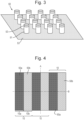
- FIG. 2 shows a small area of the security element, illustrating the arrangement of the surface of the security element across three image regions 10 in a perspective view.
- each image region has an elongate triangular prism shape, providing each image region with two facets facing away from the security document.
- the triangular prism is elongate along the direction of axis A (which corresponds to the first direction mentioned above) and has substantially constant cross-section as viewed along the direction of axis B (which corresponds to the second direction mentioned above).
- Figure 2 shows only three image regions 10, but it will be appreciated that many more are typically used to make up the full security element.
- Each image region 10 has a respective first sub-region 10a, being a facet that is inclined away from being parallel with the security document towards the viewer's left. Each first sub-region 10a across the image regions 10 has substantially the same inclination such that the first sub-regions all have the same effect on the angle of incidence of light. Each image region also has a respective second sub-region 10b, being a facet that is inclined away from being parallel with the security document towards the viewer's right. Again, all inclinations are substantially the same for each second sub-region 10b.
- FIG. 3 shows an array of plasmonic nanostructures 50 suitable for use in the present invention.
- the array of plasmonic nanostructures 50 is in the form of nanopillars.
- Each nanopillar sits on a uniform metal base layer 53 that extends across the security element surface.
- Each nanopillar comprises a dielectric shaft 51 that in this Figure is shown as being generally cylindrical.
- Each nanopillar is topped with a metal cover layer 52 that forms a nanodisc on the top of the cylindrical shaft.
- the metal base layer 53 and metal nanodiscs may be of aluminium, while the shafts of the nanopillars may be formed of hydrogen silsesquioxane (HSQ), for example, where the substrate is formed by electron beam replication.
- HSQ hydrogen silsesquioxane
- the pillar may be formed in a UV curable material typically used for cast cure replication of surface relief micro-structures, such asacrylated oligomers, such as acrylic esters of polyesters, polyethers, polyurethanes and epoxy resins, or formed in thermoplastic resins based on acrylic (PMMA) or urethane chemistries. While these are preferred, other material combinations are known to be suitable for forming plasmonic nanostructures. Typical dimensions of nanopillar include diameters between 10 and 500 nm and spacings of 50 to 500 nm.
- nanopillars shown in this figure are all the same shape and size and equally spaced, it will be appreciated that the desired colour to be generated can be tuned by mixing different sizes and shapes of nanopillar and varying the spacing. Only 16 nanopillars are shown in Figure 3 , but it will be appreciated that many more are typically used across the sub-regions of the present security device.
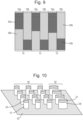
- Figure 4 shows the arrangement of plasmonic nanostructures across the security element.
- a first array of plasmonic nanostructures 50a being nanopillars having a particular shape, size and spacing
- a second array of plasmonic nanostructures 50b being nanopillars having a particular shape, size and spacing different from that of the first array 50a, are provided across each of the second sub-regions 10b, which correspond to those facets inclined towards the viewer's right.
- Figures 5A to 6B illustrate the appearance of the security element when viewed at different viewing angles upon rotation about the axis A.
- Figures 5A and 6A relate to a security element rotated about axis A such that the left-hand side of the document is closer to the viewer than the right-hand side. This effectively rotates the security element 1 about the long axis of the image regions 10 such that the first sub-regions 10a are visible while the second sub-regions 10b are obscured.
- the viewing geometry is shown in Figure 5A in particular.
- the viewing angle relative to the surface defining the second sub-regions 10b is effectively beyond 90° such that the second sub-regions are not visible.
- the image regions have widths on a scale imperceptible to the human eye and hence, as shown in Figure 6A , the appearance of the security element is of a uniform colour as generated by the first array of plasmonic nanostructures 50a.
- Figures 5B and 6B relate to the security element rotated about axis A such that the right-hand side of the document is closer to the viewer than the left-hand side. This effectively rotates the security element 1 about the long axis of the image regions 10 such that the second sub-regions 10b are visible while the first sub-regions 10a are obscured.
- the viewing geometry is shown in Figure 5B and is essentially the reverse of Figure 5B such that the viewing angle of the first sub-regions 10a is effectively beyond 90° such that the first sub-regions are not visible.
- the appearance of the security element is of a uniform colour as generated by the second array of plasmonic nanostructures 50b.
- first embodiment shows the arrays of plasmonic nanostructures provided entirely across each of the respective sets of first sub-regions 10a and second sub-regions 10b
- arrays of plasmonic nanostructures in these sub-regions may be provided only in certain areas of the sub-regions and/or may be modulated (i.e. varied in size, shape and/or spacing) across the sub-regions.
- Figures 7 to 8C illustrate an embodiment in which the plasmonic nanostructures are only in certain areas of the sub-regions.
- the same triangular prismatic shape defining sets of first and second sub-regions 10a, 10b is used as in the first embodiment.
- Figure 7 shows these triangular prismatic image regions 10 in plan view, to illustrate the manner in which the plasmonic nanostructures are provided. Specifically, it shows that the first array of plasmonic nanostructures 50a in the first sub-regions 10a is only provided in certain areas of those sub-regions so as to define an image 60a, in this case a circle. That is, each first sub-region 10a corresponds to a slice of the image to be displayed 60a and the first array 50a is provided in each first sub-region 10a so as to delimit the corresponding slice of the circle in that image.
- the second array of plasmonic nanostructures 50b in the second sub-regions 10b is only provided in certain areas of those sub-regions so as to define a second image 60b, in this case a triangle. That is, each second sub-region 10b corresponds to a slice of the image to be displayed 60b and the second array 50b is provided in each second sub-region 10b so as to delimit the corresponding slice of the triangle in that image.
- different plasmonic nanostructures are used between the first and second sub-regions to provide different colours. For both sets of sub-regions, the areas not including the first and second arrays of plasmonic nanostructures are left empty such that no colour effect is exhibited at any viewing angle in those regions.
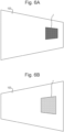
- Figures 8A to 8C illustrate the appearance of the security element 1 on a security document 100.
- Figure 8A shows the security document 1 rotated about axis A such that the left-hand side of the document is closer to the viewer than the right-hand side
- Figure 8B shows the security document 1 viewed perpendicularly
- Figure 8C shows the security document rotated about axis A such that the right-hand side of the document is closer to the viewer than the left-hand side.
- the viewing angle relative to the surface defining the second sub-regions 10b is effectively beyond 90° such that the second sub-regions 10b are not visible, while the first sub-regions 10a are visible.
- the viewer sees the first image 60a, i.e. a circle.
- first image 60a i.e. a circle.
- both the first and second images 60a, 60b are visible in superposition. That is, the images of a circle and a triangle are visible simultaneously.
- the viewing angle relative to the surface defining the first sub-regions 10a is effectively beyond 90° such that the first sub-regions are not visible, while the second sub-regions 10b become visible.
- the viewer sees the second image 60b, i.e. a triangle.
- the security element may be designed to take advantage of this feature by providing that the two images integrate in some way, e.g. by providing that the first image provides a first half of a combined image and the second image a second half of a combined image.
- the first and second images may be provided defining substantially the same image but in different colours such that rotation of the security element produces an apparent colour change of the image as different amounts of the different arrays of plasmonic nanostructures are visible.
- each first sub-region 10a is provided with an area of a first size, shape and spacing of plasmonic nanostructures 50a and an area of a second size, shape and spacing of plasmonic nanostructures 55a.
- each second sub-region 10b is provided with an area of a third size, shape and spacing of plasmonic nanostructures 50b and an area of a fourth size, shape and spacing of plasmonic nanostructures 55b.
- FIG. 10 illustrates this variation in the plasmonic nanostructures and shows first plasmonic nanostructures 50, comprising a dielectric shaft 51 and metal nanodisc 52 having a first diameter, and second plasmonic nanostructures 50, comprising a dielectric shaft 56 and metal nanodisc 57 having a second diameter. It will be appreciated that more complex modulation of the types of nanostructures can be used to produce images with more colour complexity, for example by providing many different combinations of variations in size, shape and spacing.
- FIG. 11A and 11B illustrate one option for the arrangement of the first surface.
- the image element 1 is again formed of an array of interlaced, elongate image regions 10.
- Each image region 10 has a first sub-region 10a, being an area of the surface that is substantially parallel with the plane of the security element.
- Each image region 10 also has a second sub-region 10b, formed as one facet of a groove in the first surface, the facet being inclined away from parallel with the plane of the security element, towards the viewer's right.
- the plasmonic nanostructures provided in the first sub-regions are visible over a very wide range of viewing angles as they are not obscured at substantially any viewing angle when the front surface of the security element is being viewed.
- Figure 12A and 12B illustrate an embodiment with another arrangement of the first surface of the security element 1.
- an array of elongate image regions 10 being arranged so as to repeat along a direction perpendicular to their length.
- Each image region 10 has a trapezium-shaped cross-section, as shown in Figure 12A , that is constant along the length of the image region 10. That is, three facets are defined in each image region 10 providing a first sub-region 10a that is inclined towards the viewer's left, a second sub-region 10b that is substantially parallel with the plane of the security element and a third sub-region 10c that is inclined towards the viewer's right.
- a first array of plasmonic nanostructures 50a are disposed across the first sub-regions 10a in accordance with a first image
- a second array of plasmonic nanostructures 50b are disposed across the second sub-regions 10b in accordance with a second image
- a third array of plasmonic nanostructures 50c are disposed across the third sub-regions 10c in accordance with a third image.
- This arrangement is shown for three image regions in Figure 12B .
- This embodiment provides three different images that are visible over three different viewing angle ranges, increasing the complexity of the optically variable effect.
- Figure 12A and 12B increases visual complexity; however, it may be the case that for many viewing angles more than one image is visible at the same time. For example, there may be a large range of viewing angles over which the first and second images are visible simultaneously and similarly for the second and third images. It is possible that the images used could be designed so as to integrate with one another to take advantage of this. However, in some embodiments, it is preferred to minimise the viewing angles at which multiple images are visible.
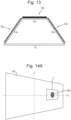
- Figures 13 to 14C illustrate such an embodiment.
- Figure 13 shows a single image region 10 of a security element 1 in cross-section.
- the image region 10 has the same shape as in the embodiment of Figures 12A and 12B . That is, each image region 10 has a trapezium-shaped cross-section that is constant along the length of the image region 10. Again, the image regions 10 are arranged so as to repeat along a direction perpendicular to the length of the image region to form the security element with a plurality of image regions.
- the first sub-region 10a of each image region 10, which is inclined towards the viewer's left, is provided with a first array of plasmonic nanostructure 50a defining a corresponding portion of a first image 60a.
- the third sub-region 10c of each image region 10, which is inclined towards the viewer's right, is provided with a third array of plasmonic nanostructure 50c defining a corresponding portion of a third image 60c.
- the second sub-region 10b of each image region 10, which is substantially parallel to the plane of the security element, is provided with a structure that defines a neutral image 60b.
- the structure may in some embodiments be an array of plasmonic nanostructures defining, for example, a uniform colour; however, in preferable embodiments, the structure is an anti-reflective structure.
- each image region 10 is completely filled with an array of anti-reflective moth-eye structures 70b defining the neutral image 60b.
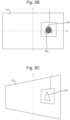
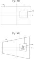
- Figures 14A to 14C illustrate the appearance of the security element 1 on a security document 100.
- Figure 14A shows the security document 1 rotated about axis A such that the left-hand side of the document is closer to the viewer than the right-hand side
- Figure 14B shows the security document 1 viewed perpendicularly
- Figure 14C shows the security document rotated about axis A such that the right-hand side of the document is closer to the viewer than the left-hand side.
- the viewing angle relative is such that the second and third sub-regions 10b, 10c are substantially not visible, while the first sub-regions 10a are visible.
- the viewer sees the first image 60a, in this case a circle.
- the second sub-regions are visible simultaneously with the first or second sub-regions, since they comprise anti-reflective structures, they do not contribute significantly to the appearance of the device and the viewer perceives only the corresponding image carried by the first or third sub-regions 10a, 10c.
- the first and third images 60a, 60c are therefore visible distinctly and separately.
- FIG 15 shows a security document 100, again a banknote, with a security element 1.
- the security document has a short axis A and a long axis B perpendicular to the short axis.
- the security element has a first surface that faces away from the security document. This first surface is made up of a two-dimension array of image regions 10.
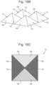
- the image regions are shown in more detail in Figures 16A to 16C .
- each image region 10 is shaped as a square based pyramid such that each image region 10 has four facets providing four different sub-regions 10a, 10b, 10c, 10d.
- the angle of inclinations of these facets shown in the Figures is schematic and the inclinations used will be selected for the desired viewing angle ranges of the plasmonic nanostructures.
- the first sub-region 10a is provided by a facet facing towards the viewer's left
- the second sub-region 10b is provided by a facet facing downwards
- the third sub-region 10c is provided by a facet facing towards the viewer's right
- the fourth sub-region is provided by a facet facing upwards.
- each sub-regions 10a, 10b, 10c, 10d is provided with a corresponding array of plasmonic nanostructures 50a, 50b, 50c, 50d, disposed according to respective first to fourth images 60a, 60b, 60c, 60d.
- the plasmonic nanostructures are shown as being present across the whole of the sub-regions (i.e. the images are uniformly coloured areas); however, this is merely for ease of demonstration and it will be appreciated that the nanostructures may be selectively provided across only certain sub-regions and certain areas of sub-regions in accordance with more complex image information and can also be modulated across the sub-regions so as to vary colour.
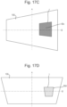
- the security element When this security document is viewed, the security element will exhibit a colour effect at four different viewing angles according to the plasmonic nanostructures on the different facets in each image region 10. These four different viewing angles are separated by rotation about both axis A and B, providing the security element with optical variability in two orthogonal directions of rotation, and this is shown in Figures 17A to 17D .
- Figure 17A shows the security element rotated from perpendicular viewing about axis A so that the left-hand side is closer to the viewer than the right-hand side.
- substantially only the first sub-region is visible and so only the colour from the first array of plasmonic nanostructures 50a is exhibited to the viewer, displaying the first image 60a.
- Figure 17B shows the security element rotated from perpendicular viewing about axis B so that the bottom of the security document is closer to the viewer than the top.
- substantially only the second sub-region 10b is visible and so only the colour from the second array of plasmonic nanostructures 50b is exhibited to the viewer, displaying the second image 60b.
- Figure 17C shows the security element rotated from perpendicular viewing about axis A so that the right-hand side is closer to the viewer than the left-hand side.
- substantially only the third sub-region is visible and so only the colour from the third array of plasmonic nanostructures 50c is exhibited to the viewer, displaying the third image 60c.
- Figure 17D shows the security element rotated from perpendicular viewing about axis B so that the top of the security document 100 is closer to the viewer than the bottom.
- substantially only the fourth sub-region is visible and so only the colour from the fourth array of plasmonic nanostructures 50d is exhibited to the viewer, displaying the fourth image 60d.
- the result is a security element that exhibits optical variability in two orthogonal directions or rotation.
- the pyramidal shape can be truncated to provide an upper facet that is parallel with the plane of the security element for carrying a neutral image.
- FIG. 18 shows another security document 100, again a banknote, with a security element 1.
- the security element in this embodiment comprises a two-dimensional array of convex dome shaped image regions 10, i.e. semi-spherical image regions, which are substantially circular in plan view, as shown in Figure 19A . While semi-spherical image regions are used here, aspherical image regions may also be used. Additionally, the thickness of the device may be decreased by using a diverging Fresnel mirror, as described above.
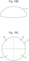
- a single image region 10 is shown in perspective view in Figure 19B , omitting the plasmonic nanostructures.
- Figure 19C shows a single image region 10 divided into a set of sub-regions.
- the image region 10 is divided into quarters so as to define four sub-regions 10a, 10b, 10c, 10d. While not shown in this embodiment, these sub-regions are assigned corresponding arrays of plasmonic nanostructures.
- the first sub-regions 10a are assigned a plasmonic nanostructure array defining a first image
- the second sub-regions are assigned a plasmonic nanostructure array defining a different second image
- the third and fourth sub-regions are assigned plasmonic nanostructure arrays defining the respective third and fourth different images.
- each sub-region will carry a respective portion of the corresponding image, such that, for example, all first image sub-regions 10a, in combination, exhibit the first iamge across the security element.
- this security element 1 is tilted about axes A and B, the four different images will be visible at different viewing angles.
- the image that is visible will correspond to the sub-region from which light is reflecting in the direction of the viewer.
- Light incident along a single direction will be directed in different directions by the different sub-regions in accordance with the local surface normal in those sub-regions.
- each sub-region is itself convex as so the local surface normal varies across each individual sub-region.
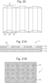
- Figure 24A shows a small area of the security element in plan view, illustrating a three by three arrangement of image regions, although again it will be appreciated that many more than this are typically provided across the full security element.
- the image regions 10 again repeat along two orthogonal directions of the security element.
- Figure 24B shows a cross-section through the image regions 10 along a first of the two orthogonal repeat directions. As illustrated in Figure 24B , each image region 10 is convex along this first repeat direction such that the sub-regions vary in average inclination along this direction.
- Figure 24C shows a cross-section through the image regions 10 along a second of the two orthogonal repeat directions and again illustrates that each image region 10 is convex along this second repeat direction.
- each image region is divided into a seven by seven array of sub-regions for a total of 49 sub-regions.
- the sub-regions are interlaced along the same two orthogonal directions along which the image regions repeat and each sub-region will thereby have a unique average inclination with respect to the plane of the security element as a result of the image region being convex along both orthogonal directions.
- the sub-regions are interlaced from left to right (from VL to VR in the Figure) along the image region as well as from top to bottom (from VU to VB in the Figure).
- each of these sub-regions is associated with a respective image.
- Respective arrays of plasmonic nanostructures are provided across the image regions such that, within each image region, each sub-region carries a corresponding portion of a respective image.
- the resulting security element will exhibit 49 different images as it is tilted along two orthogonal directions in accordance with the local surface normal across the sub-regions.
- each image region will carry a corresponding portion of a first image, such that when the security element is arranged such that incident light is reflected from each of these top-left sub-regions towards the viewer, the first image will be visible as a result of the combined appearance of these top-left sub-regions.
- each image region will effectively display a respective pixel of one of the 49 images in accordance with the viewing angle such that each of the 49 images is visible across the security device over the respective viewing angle ranges.
- each image region 10 is elongate with a constant circular segment cross-section, defining a partial cylinder shaped, or semi-cylindrical, image region 10.
- Each image region is divided lengthwise into three sub-regions 10a, 10b, 10c, which will be provided with respective arrays of plasmonic nanostructures, each defining a different respective image across the corresponding sets of sub-regions.
- each first sub-region for example, carries a different "slice" of the first image, such that the combined appearance of the first sub-region displays this first image to the viewer.
- this security element is rotated about an axis parallel with the length of the image regions 10, the three different images will be visible over different viewing angle ranges depending on the local surface normal in each of the different sub-regions 10a, 10b, 10c. That is, light incident along a single direction will be directed in different directions by the three different sub-regions in accordance with the local surface normal in those sub-regions.
- each sub-region is itself convex along the direction perpendicular to the length of the image regions, the local surface normal varies across each individual sub-region in a plane perpendicular to the length of the image regions. This acts to ensure that each image is visible over a relatively wide range of viewing angles as the security element is rotated about the axis parallel with the length of the image regions 10 and, again, prevents narrow viewing windows for each of the images.
- Figures 21A and 21B show plasmonic nanostructures in the form of an array of nanoholes 150.
- the surface of the security element 1 includes a base layer in the form of a continuous metal layer 153, such as aluminium. Over this metal layer is provided a continuous layer of dielectric material. The layer of dielectric material is then coated on its upper surface in a layer of metal 152.
- the metal layer 152 includes an array of circular holes formed through the metal layer, exposing the continuous dielectric layer.
- This structure produces plasmonic colour effects in much the same way described above with respect to nanopillar structures. Again, the shape of the holes, the size of the holes and their spacing can be varied in order to control the colour generated by these plasmonic nanostructures.
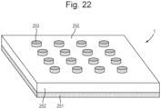
- Figure 22 shows plasmonic nanostructures in the form of an array of nanodiscs 250 on a continuous layer of dielectric material.
- the surface of the security element 1 includes a continuous metal layer 251, for example aluminium or more rarely gold, on top of which is provided a continuous dielectric layer 252, for example silicon dioxide (SiO 2 ).
- a continuous metal layer 251 for example aluminium or more rarely gold
- a continuous dielectric layer 252 for example silicon dioxide (SiO 2 ).
- SiO 2 silicon dioxide
- On the dielectric layer sits an array of circular metal nanoplates 253, again aluminium or more rarely gold is used as an example of a suitable material, that complete the nanostructure.
- the shape of the plates, the size of the plates and their spacing can be varied in order to control the colour generated by these plasmonic nanostructures.
- FIG. 23A shows a master die 200 with a negative of the desired surface structure 201.
- This surface structure in the die defines negatives of array of image regions 210, including an array of nanopillars 212 and the prismatic structure 211.
- Figure 23A also shows a transparent support layer 2, which may be a layer of the final security element 1.
- a transparent support layer 2 On the surface of the transparent support layer 2 is provided a UV curable material 3.
- the curable material 3 is directly applied onto the security document and the surface relief subsequently formed in the surface of the curable material while on the security document. This alternative requires no subsequent transferral of the security element onto a security document. In embodiments that require a metal base layer, this may be applied first to a carrier layer or security document and a curable dielectric layer applied thereover.
- a transparent die 200 may be used to cure the material on the metal layer.
- the security element may be formed directly into the substrate of the security document by using a formable polymer substrate in place of the UV curable material 3.
- Figure 23C shows the cured curable material 3, which corresponds to the first layer of the security element discussed above, after separation from the die 200.
- the cured curable material now exhibits a plurality of image regions 10 with corresponding sub-regions 10a, 10b and respective arrays of nanopillars.
- Figure 23D shows a cross section of the final security element 1 after the surface has been coated in a metal enhancing layer 4, to form the nanodiscs on the top of the nanopillars.
- the metal layer may be formed using an electron beam evaporator, which directionally deposits metal so that a metal nanodisc is formed on the tops on nanopillars.
- the security element comprises the layer of cured curable material 3 whose surface carries array of image regions 10, each having first and second sub-regions 10a, 10b, and each sub-region including first and second arrays of plasmonic nanostructures 50a, 50b.
- Security elements of the sorts described above are suitable for forming on security articles such as threads, stripes, patches, foils and the like which can then be incorporated into or applied onto security documents such as banknotes.
- security elements can also be constructed directly on security documents, such as polymer banknotes.
- Security elements of the sorts described above can be incorporated into or applied to any product for which an authenticity check is desirable.
- such devices may be applied to or incorporated into documents of value such as banknotes, passports, driving licences, cheques, identification cards etc.
- the security element can either be formed directly on the security document (e.g. on a polymer substrate forming the basis of the security document) or may be supplied as part of a security article, such as a security thread or patch, which can then be applied to or incorporated into such a document.
- the security element may be applied to a security document, for example by using a pressure sensitive adhesive.
- Such security articles can be arranged either wholly on the surface of the base substrate of the security document, as in the case of a stripe or patch, or can be visible only partly on the surface of the document substrate, e.g. in the form of a windowed security thread.
- Security threads are now present in many of the world's currencies as well as vouchers, passports, travellers' cheques and other documents. In many cases the thread is provided in a partially embedded or windowed fashion where the thread appears to weave in and out of the paper and is visible in windows in one or both surfaces of the base substrate.
- windowed threads can be found in EP 0059056 A1 .
- EP 0860298 A2 and WO 03095188 A2 describe different approaches for the embedding of wider partially exposed threads into a paper substrate.
- Wide threads typically having a width of 2 to 6mm, are particularly useful as the additional exposed thread surface area allows for better use of optically variable devices, such as that presently disclosed.
- Base substrates suitable for making security substrates for security documents may be formed from any conventional materials, including paper and polymer. Techniques are known in the art for forming substantially transparent regions in each of these types of substrate.
- WO 8300659 A1 describes a polymer banknote formed from a transparent substrate comprising an opacifying coating on both sides of the substrate. The opacifying coating is omitted in localised regions on both sides of the substrate to form a transparent region.
- the transparent substrate can be an integral part of the security element or a separate security element can be applied to the transparent substrate of the document.
- WO 0039391 A1 describes a method of making a transparent region in a paper substrate. Use of full or half-window features in this way allows the security element to be applied to one side of the security document for viewing from the opposite side, through the window.
- the security element may also be applied to one side of a paper substrate, optionally so that portions are located in an aperture formed in the paper substrate.
- An example of a method of producing such an aperture can be found in WO 03054297 A2 .
- An alternative method of incorporating a security element which is visible in apertures in one side of a paper substrate and wholly exposed on the other side of the paper substrate can be found in WO 2000/39391 A1 .
- the security element of the current invention can be made machine readable by the introduction of detectable materials in any of the layers or by the introduction of separate machine-readable layers.
- Detectable materials that react to an external stimulus include but are not limited to fluorescent, phosphorescent, infrared absorbing, thermochromic, photochromic, magnetic, electrochromic, conductive and piezochromic materials.
- the security element can be used to conceal the presence of a machine readable dark magnetic layer.
- a magnetic material When a magnetic material is incorporated into the device the magnetic material can be applied in any design but common examples include the use of magnetic tramlines or the use of magnetic blocks to form a coded structure.
- Suitable magnetic materials include iron oxide pigments (Fe 2 O 3 or Fe 3 O 4 ), barium or strontium ferrites, iron, nickel, cobalt and alloys of these.
- alloys includes materials such as Nickel:Cobalt, Iron:Aluminium:Nickel:Cobalt and the like.
- Flake Nickel materials can be used; in addition Iron flake materials are suitable. Typical nickel flakes have lateral dimensions in the range 5-50 microns and a thickness less than 2 microns. Typical iron flakes have lateral dimensions in the range 10-30 microns and a thickness less than 2 microns.
Landscapes
- Physics & Mathematics (AREA)
- Optics & Photonics (AREA)
- Business, Economics & Management (AREA)
- Accounting & Taxation (AREA)
- Finance (AREA)
- General Physics & Mathematics (AREA)
- Engineering & Computer Science (AREA)
- Chemical & Material Sciences (AREA)
- Nanotechnology (AREA)
- Biophysics (AREA)
- Life Sciences & Earth Sciences (AREA)
- Crystallography & Structural Chemistry (AREA)
- Credit Cards Or The Like (AREA)
- Diffracting Gratings Or Hologram Optical Elements (AREA)
- Burglar Alarm Systems (AREA)
Claims (15)
- Sicherheitselement (1), umfassend:eine erste Schicht mit einer ersten Oberfläche;eine Anordnung von Bildbereichen (10) über der ersten Oberfläche, wobei jeder Bildbereich mindestens einen ersten Unterbereich (10a) und einen zweiten Unterbereich (10b) umfasst;eine erste Anordnung von plasmonischen Nanostrukturen (50a), die in oder auf der ersten Oberfläche über den ersten Unterbereichen bereitgestellt sind, wobei die erste Anordnung von plasmonischen Nanostrukturen in jedem ersten Unterbereich einen entsprechenden Teil eines ersten Bildes definiert; und eine zweite Anordnung von plasmonischen Nanostrukturen (50b), die in oder auf der ersten Oberfläche über den zweiten Unterbereichen bereitgestellt sind, wobei die zweite Anordnung von plasmonischen Nanostrukturen in jedem zweiten Unterbereich einen entsprechenden Teil eines zweiten Bildes definiert;wobei die erste Oberfläche so angeordnet ist, dass jeder Unterbereich eine jeweilige durchschnittliche Neigung aufweist und wobei die durchschnittlichen Neigungen der ersten Unterbereiche so sind, dass das erste Bild mindestens bei einem ersten Betrachtungswinkel angezeigt wird, und wobei die durchschnittlichen Neigungen der zweiten Unterbereiche so sind, dass das zweite Bild mindestens bei einem zweiten Betrachtungswinkel angezeigt wird, der sich von dem ersten Betrachtungswinkel unterscheidet, und so, dass das zweite Bild mindestens bei dem ersten Betrachtungswinkel im Wesentlichen nicht angezeigt oder nur teilweise angezeigt wird; dadurch gekennzeichnet, dass:
jeder erste Unterbereich im Wesentlichen die gleiche erste durchschnittliche Neigung aufweist und/oder jeder zweite Unterbereich im Wesentlichen die gleiche zweite durchschnittliche Neigung aufweist. - Sicherheitselement nach Anspruch 1, wobei die durchschnittlichen Neigungen des ersten und des zweiten Unterbereichs so sind, dass das erste Bild mindestens bei dem zweiten Betrachtungswinkel im Wesentlichen nicht angezeigt oder nur teilweise angezeigt wird, und/oder wobei die durchschnittlichen Neigungen der ersten Unterbereiche so sind, dass das erste Bild über einen ersten Betrachtungswinkelbereich angezeigt wird, und wobei die durchschnittlichen Neigungen der zweiten Unterbereiche so sind, dass das zweite Bild über einen zweiten Betrachtungswinkelbereich angezeigt wird, wobei der erste und der zweite Betrachtungswinkelbereich einander nicht oder nur teilweise überlappen.
- Sicherheitselement nach Anspruch 1 oder Anspruch 2, wobei sich die erste und die zweite durchschnittliche Neigung um mindestens 45°, vorzugsweise mindestens 60°, bevorzugter mindestens 90° unterscheiden.
- Sicherheitselement nach einem der vorstehenden Ansprüche, wobei jede erste und/oder zweite durchschnittliche Neigung zwischen 30° und 60° liegt, vorzugsweise etwa 45° beträgt.
- Sicherheitselement nach einem der vorstehenden Ansprüche, wobei das zweite Bild eine farblich veränderte Version des ersten Bildes ist.
- Sicherheitselement nach einem der vorstehenden Ansprüche, wobei die Anordnung von Bildbereichen eine regelmäßige Anordnung von Bildbereichen umfasst und/oder wobei jeder der Bildbereiche im Wesentlichen die gleiche Größe auf der ersten Oberfläche aufweist.
- Sicherheitselement nach einem der vorstehenden Ansprüche, wobei die Anordnung von Bildbereichen eine eindimensionale Anordnung von Bildbereichen umfasst, oder wobei die Anordnung von Bildbereichen eine zweidimensionale Anordnung von Bildbereichen umfasst.
- Sicherheitselement nach einem der Ansprüche 1 bis 7, wobei die Anordnung von Bildbereichen eine Anordnung von länglichen Bildbereichen umfasst, wobei sich jeder längliche Bildbereich in einer ersten Richtung entlang der ersten Oberfläche erstreckt, wobei die Anordnung von länglichen Bildbereichen entlang einer zweiten Richtung entlang der ersten Oberfläche im Wesentlichen senkrecht zu der ersten Richtung entlang der ersten Oberfläche angeordnet ist, wobei vorzugsweise jeder längliche Bildbereich in Längsrichtung in mindestens den ersten und zweiten Unterbereich unterteilt ist.
- Sicherheitselement nach einem der vorstehenden Ansprüche, wobei jeder Bildbereich weiter einen dritten Unterbereich umfasst, wobei die erste Oberfläche so angeordnet ist, dass jeder dritte Unterbereich eine jeweilige durchschnittliche Neigung aufweist, wobei vorzugsweise die erste Oberfläche so angeordnet ist, dass dritte Unterbereiche mindestens bei einem dritten Betrachtungswinkel sichtbar sind, wobei der dritte Betrachtungswinkel zwischen dem ersten und dem zweiten Betrachtungswinkel liegt, und/oder wobei vorzugsweise jeder dritte Unterbereich im Wesentlichen die gleiche dritte durchschnittliche Neigung aufweist, und wobei weiter vorzugsweise jeder dritte Unterbereich im Wesentlichen parallel zu einer Ebene des Sicherheitselements ist, und vorzugsweise weiter eine einheitliche Struktur umfasst, die über die dritten Unterbereiche bereitgestellt wird und ein neutrales Bild definiert, wobei die einheitliche Struktur vorzugsweise eine im Wesentlichen planare reflektierende Oberfläche, eine Anordnung von antireflektierenden Mikrostrukturen, eine Anordnung von plasmonischen Nanostrukturen, die eine einheitliche Farbe definieren, oder ein oder mehrere Beugungsgitter umfasst.
- Sicherheitselement nach Anspruch 9, weiter umfassend eine dritte Anordnung von plasmonischen Nanostrukturen, die in oder auf der ersten Oberfläche über den dritten Unterbereichen bereitgestellt sind, wobei die dritte Anordnung von plasmonischen Nanostrukturen in jedem dritten Unterbereich einen entsprechenden Teil eines dritten Bildes definiert, wobei vorzugsweise die durchschnittlichen Neigungen der dritten Unterbereiche so sind, dass das dritte Bild mindestens bei einem dritten Betrachtungswinkel angezeigt wird, und wobei weiter vorzugsweise die durchschnittlichen Neigungen der dritten Unterbereiche so sind, dass das dritte Bild mindestens bei dem ersten Betrachtungswinkel und/oder mindestens bei dem zweiten Betrachtungswinkel im Wesentlichen nicht angezeigt wird.
- Sicherheitselement nach einem der vorstehenden Ansprüche, wobei die plasmonischen Nanostrukturen der ersten, zweiten und/oder dritten Anordnungen von plasmonischen Nanostrukturen diskontinuierlich über den entsprechenden ersten, zweiten und/oder dritten Unterbereichen bereitgestellt sind, um Bildinformationen des entsprechenden ersten, zweiten und/oder dritten Bildes bereitzustellen, und/oder wobei die plasmonischen Nanostrukturen der ersten, zweiten und/oder dritten Anordnungen von plasmonischen Nanostrukturen in mindestens einem von ihrer Form, Größe und Abstand über die entsprechenden ersten, zweiten und/oder dritten Unterbereiche variieren, um Bildinformationen des entsprechenden ersten, zweiten und/oder dritten Bildes bereitzustellen.
- Sicherheitselement nach einem der vorstehenden Ansprüche, wobei jeder erste und/oder zweite Unterbereich auf der ersten Oberfläche eine Breite von 5 bis 50 µm, vorzugsweise 10 bis 40 µm, aufweist.
- Sicherheitselement nach einem der vorstehenden Ansprüche, wobei die erste und/oder zweite Anordnung von plasmonischen Nanostrukturen eines oder mehrere umfasst von: einer zweidimensionalen Anordnung von Nanosäulen, wobei jede Nanosäule einen dielektrischen Körper, der von einer kontinuierlichen Metalldeckschicht bedeckt ist, eine kontinuierliche Metallbasisschicht, eine kontinuierliche dielektrische Schicht auf der kontinuierlichen Metallbasisschicht und eine zweidimensionale Anordnung von metallischen Nanoscheiben auf der kontinuierlichen dielektrischen Schicht, die die kontinuierliche Metallbasisschicht überlappt, umfasst, einer zweidimensionalen Anordnung von Nanolöchern, wobei jedes Nanoloch eine Öffnung durch eine Metallschicht umfasst, wobei die Metallschicht auf einem Substrat angeordnet ist, und eine eindimensionale oder zweidimensionale Sub-Wellenlängen-Gitterstruktur, die in einer dielektrischen Schicht ausgebildet ist, wobei die eindimensionale oder zweidimensionale Sub-Wellenlängen-Gitterstruktur mit einer Metallschicht beschichtet ist.
- Sicherheitselement nach einem der vorstehenden Ansprüche, wobei die erste Oberfläche so angeordnet ist, dass jeder erste und/oder zweite Unterbereich im Wesentlichen konvex ist und/oder wobei die erste Oberfläche so angeordnet ist, dass sie ein im Wesentlichen konvexes Oberflächenelement in jedem Bildbereich definiert und wobei jeder erste Unterbereich ein erster Unterbereich eines entsprechenden im Wesentlichen konvexen Oberflächenelements ist und wobei jeder zweite Unterbereich ein zweiter Unterbereich eines entsprechenden im Wesentlichen konvexen Oberflächenelements ist, und/oder wobei die Anordnung von Bildbereichen eine zweidimensionale Anordnung von Bildbereichen umfasst, wobei jeder Bildbereich entlang zweier orthogonaler Richtungen im Wesentlichen konvex ist, und wobei jeder Bildbereich eine zweidimensionale Anordnung von konvexen Unterbereichen mit unterschiedlichen durchschnittlichen Neigungen definiert, wobei jeder Satz von Unterbereichen eine jeweilige Anordnung von plasmonischen Nanostrukturen umfasst, die entsprechende Teile eines jeweiligen Bildes definieren, so dass die unterschiedlichen Bilder bei unterschiedlichen Betrachtungswinkeln in zwei orthogonalen Neigungsrichtungen des Sicherheitselements durch die entsprechenden Unterbereiche in Kombination gezeigt werden.
- Verfahren zur Herstellung eines Sicherheitselements, umfassend:Bereitstellen einer ersten Schicht mit einer ersten OberflächeAusbilden der ersten Oberfläche der ersten Schicht, um eine Anordnung von Bildbereichen über der ersten Oberfläche zu definieren, wobei jeder Bildbereich mindestens einen ersten Unterbereich und einen zweiten Unterbereich umfasst, wobei jeder Unterbereich eine entsprechende durchschnittliche Neigung aufweist;Bereitstellen einer ersten Anordnung von plasmonischen Nanostrukturen in oder auf der ersten Oberfläche über den ersten Unterbereichen, die in jedem ersten Unterbereich einen entsprechenden Teil eines ersten Bildes definieren; undBereitstellen einer zweiten Anordnung von plasmonischen Nanostrukturen in oder auf der ersten Oberfläche über den zweiten Unterbereichen, die in jedem zweiten Unterbereich einen entsprechenden Teil eines zweiten Bildes definieren;wobei die durchschnittlichen Neigungen der ersten Unterbereiche so sind, dass das erste Bild mindestens bei einem ersten Betrachtungswinkel angezeigt wird, und wobei die durchschnittlichen Neigungen der zweiten Unterbereiche so sind, dass das zweite Bild mindestens bei einem zweiten Betrachtungswinkel angezeigt wird, der sich von dem ersten Betrachtungswinkel unterscheidet, und so, dass das zweite Bild mindestens bei dem ersten Betrachtungswinkel im Wesentlichen nicht angezeigt wird;dadurch gekennzeichnet, dass:
jeder erste Unterbereich im Wesentlichen die gleiche erste durchschnittliche Neigung aufweist und/oder jeder zweite Unterbereich im Wesentlichen die gleiche zweite durchschnittliche Neigung aufweist.
Priority Applications (1)
| Application Number | Priority Date | Filing Date | Title |
|---|---|---|---|
| EP25158822.4A EP4600046A3 (de) | 2018-03-22 | 2019-03-22 | Sicherheitselemente und verfahren zu ihrer herstellung |
Applications Claiming Priority (2)
| Application Number | Priority Date | Filing Date | Title |
|---|---|---|---|
| GB1804630.0A GB2572746B (en) | 2018-03-22 | 2018-03-22 | Security elements and method of manufacture thereof |
| PCT/GB2019/050829 WO2019180460A1 (en) | 2018-03-22 | 2019-03-22 | Security elements and methods of manufacture thereof |
Related Child Applications (2)
| Application Number | Title | Priority Date | Filing Date |
|---|---|---|---|
| EP25158822.4A Division EP4600046A3 (de) | 2018-03-22 | 2019-03-22 | Sicherheitselemente und verfahren zu ihrer herstellung |
| EP25158822.4A Division-Into EP4600046A3 (de) | 2018-03-22 | 2019-03-22 | Sicherheitselemente und verfahren zu ihrer herstellung |
Publications (2)
| Publication Number | Publication Date |
|---|---|
| EP3768518A1 EP3768518A1 (de) | 2021-01-27 |
| EP3768518B1 true EP3768518B1 (de) | 2025-04-30 |
Family
ID=62068047
Family Applications (2)
| Application Number | Title | Priority Date | Filing Date |
|---|---|---|---|
| EP25158822.4A Pending EP4600046A3 (de) | 2018-03-22 | 2019-03-22 | Sicherheitselemente und verfahren zu ihrer herstellung |
| EP19714763.0A Active EP3768518B1 (de) | 2018-03-22 | 2019-03-22 | Sicherheitselemente und verfahren zur herstellung davon |
Family Applications Before (1)
| Application Number | Title | Priority Date | Filing Date |
|---|---|---|---|
| EP25158822.4A Pending EP4600046A3 (de) | 2018-03-22 | 2019-03-22 | Sicherheitselemente und verfahren zu ihrer herstellung |
Country Status (6)
| Country | Link |
|---|---|
| US (3) | US20210070091A1 (de) |
| EP (2) | EP4600046A3 (de) |
| AU (1) | AU2019240023B2 (de) |
| CA (1) | CA3092821A1 (de) |
| GB (1) | GB2572746B (de) |
| WO (1) | WO2019180460A1 (de) |
Families Citing this family (12)
| Publication number | Priority date | Publication date | Assignee | Title |
|---|---|---|---|---|
| GB2578773B (en) * | 2018-11-08 | 2022-03-30 | De La Rue Int Ltd | Methods of manufacturing security device components |
| GB2585703B (en) | 2019-07-12 | 2023-02-22 | De La Rue Int Ltd | Security devices and methods of manufacture |
| GB2589818B (en) | 2019-07-12 | 2022-12-14 | De La Rue Int Ltd | Security devices and methods of manufacture thereof |
| FR3107004B1 (fr) * | 2020-02-12 | 2025-03-28 | Ccl Secure Pty | Dispositif a effet optique |
| EP3896529B1 (de) * | 2020-04-13 | 2024-08-28 | Kaunas University of Technology | Verfahren zur herstellung eines holographischen sicherheitsetiketts |
| GB202018041D0 (en) * | 2020-11-17 | 2020-12-30 | De La Rue Int Ltd | Security device and method of manufacture thereof |
| GB202019383D0 (en) | 2020-12-09 | 2021-01-20 | De La Rue Int Ltd | Security device and method of manfacture thereof |
| DE102021002599A1 (de) * | 2021-05-18 | 2022-11-24 | Giesecke+Devrient Currency Technology Gmbh | Optisch variables Darstellungselement |
| DE102021003185A1 (de) * | 2021-06-21 | 2022-12-22 | Giesecke+Devrient Currency Technology Gmbh | Optisch variables Sicherheitselement und Wertdokument mit dem optisch variablen Sicherheitselement |
| EP4511238A1 (de) * | 2022-04-19 | 2025-02-26 | Authentix, Inc. | Auf metaoberfläche basierende fälschungssichere vorrichtung |
| DE102022003230A1 (de) | 2022-09-02 | 2024-03-07 | Giesecke+Devrient Currency Technology Gmbh | Sicherheitselement mit farberzeugenden Nanostrukturen und Herstellverfahren dafür |
| EP4624185A1 (de) * | 2024-03-27 | 2025-10-01 | Thales Dis France Sas | Datenträger and dessen herstellungsverfahren |
Citations (14)
| Publication number | Priority date | Publication date | Assignee | Title |
|---|---|---|---|---|
| WO2003084764A2 (de) | 2002-04-05 | 2003-10-16 | Ovd Kinegram Ag | Sicherheitselement mit mikro- und makrostrukturen |
| JP2010197798A (ja) | 2009-02-26 | 2010-09-09 | Toppan Printing Co Ltd | 偽造防止機能を有する光学素子及びそれを具備する偽造防止表示体 |
| DE102009012300A1 (de) | 2009-03-11 | 2010-09-16 | Giesecke & Devrient Gmbh | Sicherheitselement mit mehrfarbigem Bild |
| WO2011066991A2 (de) | 2009-12-04 | 2011-06-09 | Giesecke & Devrient Gmbh | Sicherheitselement, wertdokument mit einem solchen sicherheitselement sowie herstellungsverfahren eines sicherheitselementes |
| DE102010049831A1 (de) | 2010-10-27 | 2012-05-03 | Giesecke & Devrient Gmbh | Optisch variables Flächenmuster |
| FR2973917A1 (fr) | 2011-04-08 | 2012-10-12 | Hologram Ind | Composant optique de securite a effet transmissif, fabrication d'un tel composant et document securise equipe d'un tel composant |
| FR2982038A1 (fr) | 2011-10-28 | 2013-05-03 | Hologram Ind | Composant optique de securite a effet reflectif, fabrication d'un tel composant et document securise equipe d'un tel composant |
| US20140092718A1 (en) | 2012-09-28 | 2014-04-03 | Agency For Science, Technology And Research | Method of writing to an optical data storage medium, method of reading from an optical data storage medium, and optical data storage medium |
| WO2014072358A1 (de) | 2012-11-06 | 2014-05-15 | Ovd Kinegram Ag | Mehrschichtkörper sowie verfahren zur herstellung eines sicherheitselements |
| WO2015154943A1 (fr) | 2014-04-07 | 2015-10-15 | Hologram.Industries | Composant optique de securite a effet reflectif, fabrication d'un tel composant et document securisé equipé d'un tel composant |
| EP3000613A1 (de) | 2014-09-23 | 2016-03-30 | Giesecke & Devrient GmbH | Optisch variables sicherheitselement mit reflektivem flächenbereich |
| WO2018224513A1 (fr) | 2017-06-06 | 2018-12-13 | Surys | Composant optique de securite visible en reflexion, fabrication d'un tel composant et document securisé equipé d'un tel composant |
| EP3470235A1 (de) | 2017-10-10 | 2019-04-17 | Surys | Optische sicherheitskomponente mit reflexionseffekt und herstellung einer solchen komponente |
| WO2019140527A1 (en) | 2018-01-17 | 2019-07-25 | Nanotech Security Corp. | Nano-structures patterned on micro-structures |
Family Cites Families (20)
| Publication number | Priority date | Publication date | Assignee | Title |
|---|---|---|---|---|
| IN157644B (de) | 1981-02-19 | 1986-05-10 | Portals Ltd | |
| US4536016A (en) | 1981-08-24 | 1985-08-20 | Solomon David H | Banknotes and the like |
| DE4314380B4 (de) | 1993-05-01 | 2009-08-06 | Giesecke & Devrient Gmbh | Sicherheitspapier und Verfahren zu seiner Herstellung |
| GB9828770D0 (en) | 1998-12-29 | 1999-02-17 | Rue De Int Ltd | Security paper |
| DE10163381A1 (de) | 2001-12-21 | 2003-07-03 | Giesecke & Devrient Gmbh | Sicherheitspapier sowie Verfahren und Vorrichtung zu seiner Herstellung |
| GB2388377B (en) | 2002-05-09 | 2004-07-28 | Rue De Int Ltd | A paper sheet incorporating a security element and a method of making the same |
| DE102009004128A1 (de) | 2009-01-05 | 2010-07-08 | Giesecke & Devrient Gmbh | Sicherheitselement mit optisch variabler Struktur |
| DE102009056934A1 (de) | 2009-12-04 | 2011-06-09 | Giesecke & Devrient Gmbh | Sicherheitselement, Wertdokument mit einem solchen Sicherheitselement sowie Herstellungsverfahren eines Sicherheitselementes |
| WO2013039454A1 (en) * | 2011-09-12 | 2013-03-21 | Agency For Science, Technology And Research | An optical arrangement and a method of forming the same |
| GB201313363D0 (en) * | 2013-07-26 | 2013-09-11 | Rue De Int Ltd | Security devices and method of manufacture |
| FR3017231B1 (fr) * | 2014-01-31 | 2020-07-24 | Hologram Ind | Composant optique de securite a effet plasmonique, fabrication d'un tel composant et document securise equipe d'un tel composant |
| GB201410620D0 (en) | 2014-06-13 | 2014-07-30 | Api Holographics | Optically variable element |
| DE102015202106A1 (de) | 2015-02-06 | 2016-08-11 | Tesa Scribos Gmbh | Optisch variables Sicherheitselement |
| EP3303213A4 (de) * | 2015-06-02 | 2018-08-15 | The University of Melbourne | Verfahren und vorrichtung zur darstellung eines bildes mit plasmonischen pixeln |
| WO2017015748A1 (en) * | 2015-07-25 | 2017-02-02 | NanoMedia Solutions Inc. | Color image display devices comprising structural color pixels that are selectively activated and/or deactivated by material deposition |
| FR3040015B1 (fr) * | 2015-08-11 | 2017-09-08 | Hologram Ind | Composant optique de securite a effet plasmonique et procede de fabrication d'un tel composant |
| WO2017184581A1 (en) * | 2016-04-22 | 2017-10-26 | Wavefront Technology, Inc. | Optical switch devices |
| DE102016015393A1 (de) * | 2016-12-22 | 2018-06-28 | Giesecke+Devrient Currency Technology Gmbh | Sicherheitselement mit reflektivem Flächenbereich |
| CN108422764A (zh) * | 2017-02-15 | 2018-08-21 | 中钞特种防伪科技有限公司 | 光学防伪元件及光学防伪产品 |
| CN112572015B (zh) * | 2019-09-30 | 2023-06-06 | 中钞特种防伪科技有限公司 | 光学防伪元件及防伪产品 |
-
2018
- 2018-03-22 GB GB1804630.0A patent/GB2572746B/en active Active
-
2019
- 2019-03-22 US US17/040,413 patent/US20210070091A1/en not_active Abandoned
- 2019-03-22 CA CA3092821A patent/CA3092821A1/en active Pending
- 2019-03-22 AU AU2019240023A patent/AU2019240023B2/en active Active
- 2019-03-22 EP EP25158822.4A patent/EP4600046A3/de active Pending
- 2019-03-22 EP EP19714763.0A patent/EP3768518B1/de active Active
- 2019-03-22 WO PCT/GB2019/050829 patent/WO2019180460A1/en not_active Ceased
-
2023
- 2023-03-06 US US18/117,624 patent/US12539713B2/en active Active
-
2024
- 2024-05-17 US US18/667,428 patent/US20240300257A1/en active Pending
Patent Citations (14)
| Publication number | Priority date | Publication date | Assignee | Title |
|---|---|---|---|---|
| WO2003084764A2 (de) | 2002-04-05 | 2003-10-16 | Ovd Kinegram Ag | Sicherheitselement mit mikro- und makrostrukturen |
| JP2010197798A (ja) | 2009-02-26 | 2010-09-09 | Toppan Printing Co Ltd | 偽造防止機能を有する光学素子及びそれを具備する偽造防止表示体 |
| DE102009012300A1 (de) | 2009-03-11 | 2010-09-16 | Giesecke & Devrient Gmbh | Sicherheitselement mit mehrfarbigem Bild |
| WO2011066991A2 (de) | 2009-12-04 | 2011-06-09 | Giesecke & Devrient Gmbh | Sicherheitselement, wertdokument mit einem solchen sicherheitselement sowie herstellungsverfahren eines sicherheitselementes |
| DE102010049831A1 (de) | 2010-10-27 | 2012-05-03 | Giesecke & Devrient Gmbh | Optisch variables Flächenmuster |
| FR2973917A1 (fr) | 2011-04-08 | 2012-10-12 | Hologram Ind | Composant optique de securite a effet transmissif, fabrication d'un tel composant et document securise equipe d'un tel composant |
| FR2982038A1 (fr) | 2011-10-28 | 2013-05-03 | Hologram Ind | Composant optique de securite a effet reflectif, fabrication d'un tel composant et document securise equipe d'un tel composant |
| US20140092718A1 (en) | 2012-09-28 | 2014-04-03 | Agency For Science, Technology And Research | Method of writing to an optical data storage medium, method of reading from an optical data storage medium, and optical data storage medium |
| WO2014072358A1 (de) | 2012-11-06 | 2014-05-15 | Ovd Kinegram Ag | Mehrschichtkörper sowie verfahren zur herstellung eines sicherheitselements |
| WO2015154943A1 (fr) | 2014-04-07 | 2015-10-15 | Hologram.Industries | Composant optique de securite a effet reflectif, fabrication d'un tel composant et document securisé equipé d'un tel composant |
| EP3000613A1 (de) | 2014-09-23 | 2016-03-30 | Giesecke & Devrient GmbH | Optisch variables sicherheitselement mit reflektivem flächenbereich |
| WO2018224513A1 (fr) | 2017-06-06 | 2018-12-13 | Surys | Composant optique de securite visible en reflexion, fabrication d'un tel composant et document securisé equipé d'un tel composant |
| EP3470235A1 (de) | 2017-10-10 | 2019-04-17 | Surys | Optische sicherheitskomponente mit reflexionseffekt und herstellung einer solchen komponente |
| WO2019140527A1 (en) | 2018-01-17 | 2019-07-25 | Nanotech Security Corp. | Nano-structures patterned on micro-structures |
Non-Patent Citations (1)
| Title |
|---|
| HANS LOCHBIHLER: "Colored images generated by metallic sub-wavelength gratings", OPTICS EXPRESS, OSA, vol. 17, no. 14, 2 July 2009 (2009-07-02), pages 12189 - 12196, XP055365719, DOI: https://doi.org/10.1364/OE.17.012189 |
Also Published As
| Publication number | Publication date |
|---|---|
| EP4600046A2 (de) | 2025-08-13 |
| US20210070091A1 (en) | 2021-03-11 |
| GB2572746B (en) | 2021-10-27 |
| WO2019180460A1 (en) | 2019-09-26 |
| US20230202223A1 (en) | 2023-06-29 |
| AU2019240023B2 (en) | 2023-08-24 |
| GB201804630D0 (en) | 2018-05-09 |
| AU2019240023A1 (en) | 2020-09-24 |
| EP4600046A3 (de) | 2025-09-24 |
| CA3092821A1 (en) | 2019-09-26 |
| EP3768518A1 (de) | 2021-01-27 |
| US12539713B2 (en) | 2026-02-03 |
| GB2572746A (en) | 2019-10-16 |
| US20240300257A1 (en) | 2024-09-12 |
Similar Documents
| Publication | Publication Date | Title |
|---|---|---|
| US12539713B2 (en) | Security elements and method of manufacture thereof | |
| US9070237B2 (en) | Moire magnification device | |
| EP3174730B1 (de) | Sicherheitsvorrichtungen und verfahren zur herstellung davon | |
| EP3877192B1 (de) | Verfahren zur herstellung von bestandteilen einer sicherheitsvorrichtung | |
| AU2019240024B2 (en) | Security elements and methods of manufacture thereof | |
| EP3996932B1 (de) | Sicherheitsvorrichtungen und verfahren zur herstellung | |
| EP3996931B1 (de) | Sicherheitsvorrichtungen und verfahren zur herstellung davon | |
| CA3030791A1 (en) | Methods of manufacturing a security device |
Legal Events
| Date | Code | Title | Description |
|---|---|---|---|
| STAA | Information on the status of an ep patent application or granted ep patent |
Free format text: STATUS: UNKNOWN |
|
| STAA | Information on the status of an ep patent application or granted ep patent |
Free format text: STATUS: THE INTERNATIONAL PUBLICATION HAS BEEN MADE |
|
| PUAI | Public reference made under article 153(3) epc to a published international application that has entered the european phase |
Free format text: ORIGINAL CODE: 0009012 |
|
| STAA | Information on the status of an ep patent application or granted ep patent |
Free format text: STATUS: REQUEST FOR EXAMINATION WAS MADE |
|
| 17P | Request for examination filed |
Effective date: 20201022 |
|
| AK | Designated contracting states |
Kind code of ref document: A1 Designated state(s): AL AT BE BG CH CY CZ DE DK EE ES FI FR GB GR HR HU IE IS IT LI LT LU LV MC MK MT NL NO PL PT RO RS SE SI SK SM TR |
|
| AX | Request for extension of the european patent |
Extension state: BA ME |
|
| DAV | Request for validation of the european patent (deleted) | ||
| DAX | Request for extension of the european patent (deleted) | ||
| STAA | Information on the status of an ep patent application or granted ep patent |
Free format text: STATUS: EXAMINATION IS IN PROGRESS |
|
| 17Q | First examination report despatched |
Effective date: 20211013 |
|
| TPAC | Observations filed by third parties |
Free format text: ORIGINAL CODE: EPIDOSNTIPA |
|
| GRAP | Despatch of communication of intention to grant a patent |
Free format text: ORIGINAL CODE: EPIDOSNIGR1 |
|
| STAA | Information on the status of an ep patent application or granted ep patent |
Free format text: STATUS: GRANT OF PATENT IS INTENDED |
|
| INTG | Intention to grant announced |
Effective date: 20241205 |
|
| GRAS | Grant fee paid |
Free format text: ORIGINAL CODE: EPIDOSNIGR3 |
|
| GRAA | (expected) grant |
Free format text: ORIGINAL CODE: 0009210 |
|
| STAA | Information on the status of an ep patent application or granted ep patent |
Free format text: STATUS: THE PATENT HAS BEEN GRANTED |
|
| P01 | Opt-out of the competence of the unified patent court (upc) registered |
Free format text: CASE NUMBER: APP_8910/2025 Effective date: 20250221 |
|
| RBV | Designated contracting states (corrected) |
Designated state(s): AL AT BE BG CH CY CZ DE DK EE ES FI FR GR HR HU IE IS IT LI LT LU LV MC MK MT NL NO PL PT RO RS SE SI SK SM TR |
|
| AK | Designated contracting states |
Kind code of ref document: B1 Designated state(s): AL AT BE BG CH CY CZ DE DK EE ES FI FR GR HR HU IE IS IT LI LT LU LV MC MK MT NL NO PL PT RO RS SE SI SK SM TR |
|
| REG | Reference to a national code |
Ref country code: CH Ref legal event code: EP |
|
| REG | Reference to a national code |
Ref country code: DE Ref legal event code: R096 Ref document number: 602019069292 Country of ref document: DE |
|
| REG | Reference to a national code |
Ref country code: IE Ref legal event code: FG4D |
|
| REG | Reference to a national code |
Ref country code: NL Ref legal event code: MP Effective date: 20250430 |
|
| PG25 | Lapsed in a contracting state [announced via postgrant information from national office to epo] |
Ref country code: PT Free format text: LAPSE BECAUSE OF FAILURE TO SUBMIT A TRANSLATION OF THE DESCRIPTION OR TO PAY THE FEE WITHIN THE PRESCRIBED TIME-LIMIT Effective date: 20250901 Ref country code: FI Free format text: LAPSE BECAUSE OF FAILURE TO SUBMIT A TRANSLATION OF THE DESCRIPTION OR TO PAY THE FEE WITHIN THE PRESCRIBED TIME-LIMIT Effective date: 20250430 Ref country code: ES Free format text: LAPSE BECAUSE OF FAILURE TO SUBMIT A TRANSLATION OF THE DESCRIPTION OR TO PAY THE FEE WITHIN THE PRESCRIBED TIME-LIMIT Effective date: 20250430 |
|
| REG | Reference to a national code |
Ref country code: LT Ref legal event code: MG9D |
|
| PG25 | Lapsed in a contracting state [announced via postgrant information from national office to epo] |
Ref country code: NO Free format text: LAPSE BECAUSE OF FAILURE TO SUBMIT A TRANSLATION OF THE DESCRIPTION OR TO PAY THE FEE WITHIN THE PRESCRIBED TIME-LIMIT Effective date: 20250730 Ref country code: GR Free format text: LAPSE BECAUSE OF FAILURE TO SUBMIT A TRANSLATION OF THE DESCRIPTION OR TO PAY THE FEE WITHIN THE PRESCRIBED TIME-LIMIT Effective date: 20250731 |
|
| PG25 | Lapsed in a contracting state [announced via postgrant information from national office to epo] |
Ref country code: PL Free format text: LAPSE BECAUSE OF FAILURE TO SUBMIT A TRANSLATION OF THE DESCRIPTION OR TO PAY THE FEE WITHIN THE PRESCRIBED TIME-LIMIT Effective date: 20250430 Ref country code: NL Free format text: LAPSE BECAUSE OF FAILURE TO SUBMIT A TRANSLATION OF THE DESCRIPTION OR TO PAY THE FEE WITHIN THE PRESCRIBED TIME-LIMIT Effective date: 20250430 |
|
| PG25 | Lapsed in a contracting state [announced via postgrant information from national office to epo] |
Ref country code: HR Free format text: LAPSE BECAUSE OF FAILURE TO SUBMIT A TRANSLATION OF THE DESCRIPTION OR TO PAY THE FEE WITHIN THE PRESCRIBED TIME-LIMIT Effective date: 20250430 |
|
| PG25 | Lapsed in a contracting state [announced via postgrant information from national office to epo] |
Ref country code: RS Free format text: LAPSE BECAUSE OF FAILURE TO SUBMIT A TRANSLATION OF THE DESCRIPTION OR TO PAY THE FEE WITHIN THE PRESCRIBED TIME-LIMIT Effective date: 20250731 |
|
| PG25 | Lapsed in a contracting state [announced via postgrant information from national office to epo] |
Ref country code: IS Free format text: LAPSE BECAUSE OF FAILURE TO SUBMIT A TRANSLATION OF THE DESCRIPTION OR TO PAY THE FEE WITHIN THE PRESCRIBED TIME-LIMIT Effective date: 20250830 |
|
| PG25 | Lapsed in a contracting state [announced via postgrant information from national office to epo] |
Ref country code: LV Free format text: LAPSE BECAUSE OF FAILURE TO SUBMIT A TRANSLATION OF THE DESCRIPTION OR TO PAY THE FEE WITHIN THE PRESCRIBED TIME-LIMIT Effective date: 20250430 |
|
| PG25 | Lapsed in a contracting state [announced via postgrant information from national office to epo] |
Ref country code: DK Free format text: LAPSE BECAUSE OF FAILURE TO SUBMIT A TRANSLATION OF THE DESCRIPTION OR TO PAY THE FEE WITHIN THE PRESCRIBED TIME-LIMIT Effective date: 20250430 Ref country code: SM Free format text: LAPSE BECAUSE OF FAILURE TO SUBMIT A TRANSLATION OF THE DESCRIPTION OR TO PAY THE FEE WITHIN THE PRESCRIBED TIME-LIMIT Effective date: 20250430 |
|
| PGFP | Annual fee paid to national office [announced via postgrant information from national office to epo] |
Ref country code: FR Payment date: 20251231 Year of fee payment: 8 |
|
| PG25 | Lapsed in a contracting state [announced via postgrant information from national office to epo] |
Ref country code: EE Free format text: LAPSE BECAUSE OF FAILURE TO SUBMIT A TRANSLATION OF THE DESCRIPTION OR TO PAY THE FEE WITHIN THE PRESCRIBED TIME-LIMIT Effective date: 20250430 |
|
| PG25 | Lapsed in a contracting state [announced via postgrant information from national office to epo] |
Ref country code: RO Free format text: LAPSE BECAUSE OF FAILURE TO SUBMIT A TRANSLATION OF THE DESCRIPTION OR TO PAY THE FEE WITHIN THE PRESCRIBED TIME-LIMIT Effective date: 20250430 Ref country code: SK Free format text: LAPSE BECAUSE OF FAILURE TO SUBMIT A TRANSLATION OF THE DESCRIPTION OR TO PAY THE FEE WITHIN THE PRESCRIBED TIME-LIMIT Effective date: 20250430 |
|
| PLBI | Opposition filed |
Free format text: ORIGINAL CODE: 0009260 |
|
| REG | Reference to a national code |
Ref country code: CH Ref legal event code: L10 Free format text: ST27 STATUS EVENT CODE: U-0-0-L10-L00 (AS PROVIDED BY THE NATIONAL OFFICE) Effective date: 20260211 |
|
| PLAX | Notice of opposition and request to file observation + time limit sent |
Free format text: ORIGINAL CODE: EPIDOSNOBS2 |