EP3766680B1 - Work station for a packing machine - Google Patents
Work station for a packing machine Download PDFInfo
- Publication number
- EP3766680B1 EP3766680B1 EP20184953.6A EP20184953A EP3766680B1 EP 3766680 B1 EP3766680 B1 EP 3766680B1 EP 20184953 A EP20184953 A EP 20184953A EP 3766680 B1 EP3766680 B1 EP 3766680B1
- Authority
- EP
- European Patent Office
- Prior art keywords
- hose
- insert
- closure
- working station
- seal
- Prior art date
- Legal status (The legal status is an assumption and is not a legal conclusion. Google has not performed a legal analysis and makes no representation as to the accuracy of the status listed.)
- Active
Links
- 238000012856 packing Methods 0.000 title 1
- 238000004806 packaging method and process Methods 0.000 claims description 38
- 238000005520 cutting process Methods 0.000 claims description 19
- 238000007789 sealing Methods 0.000 claims description 14
- 239000012530 fluid Substances 0.000 claims description 8
- 239000010408 film Substances 0.000 description 22
- 206010053648 Vascular occlusion Diseases 0.000 description 4
- 239000013039 cover film Substances 0.000 description 3
- 238000003780 insertion Methods 0.000 description 3
- 230000037431 insertion Effects 0.000 description 3
- 210000002445 nipple Anatomy 0.000 description 3
- 238000001514 detection method Methods 0.000 description 2
- 239000000463 material Substances 0.000 description 2
- 238000000034 method Methods 0.000 description 2
- 210000003205 muscle Anatomy 0.000 description 2
- 238000003825 pressing Methods 0.000 description 2
- 238000003860 storage Methods 0.000 description 2
- 230000032683 aging Effects 0.000 description 1
- 230000008602 contraction Effects 0.000 description 1
- 230000001419 dependent effect Effects 0.000 description 1
- 238000011161 development Methods 0.000 description 1
- 230000018109 developmental process Effects 0.000 description 1
- 230000002349 favourable effect Effects 0.000 description 1
- 238000011010 flushing procedure Methods 0.000 description 1
- 239000011888 foil Substances 0.000 description 1
- 239000000203 mixture Substances 0.000 description 1
- 238000000465 moulding Methods 0.000 description 1
- 238000004080 punching Methods 0.000 description 1
- 238000003856 thermoforming Methods 0.000 description 1
Images

Classifications
-
- B—PERFORMING OPERATIONS; TRANSPORTING
- B65—CONVEYING; PACKING; STORING; HANDLING THIN OR FILAMENTARY MATERIAL
- B65B—MACHINES, APPARATUS OR DEVICES FOR, OR METHODS OF, PACKAGING ARTICLES OR MATERIALS; UNPACKING
- B65B35/00—Supplying, feeding, arranging or orientating articles to be packaged
- B65B35/10—Feeding, e.g. conveying, single articles
- B65B35/20—Feeding, e.g. conveying, single articles by reciprocating or oscillatory pushers
-
- B—PERFORMING OPERATIONS; TRANSPORTING
- B30—PRESSES
- B30B—PRESSES IN GENERAL
- B30B5/00—Presses characterised by the use of pressing means other than those mentioned in the preceding groups
- B30B5/02—Presses characterised by the use of pressing means other than those mentioned in the preceding groups wherein the pressing means is in the form of a flexible element, e.g. diaphragm, urged by fluid pressure
-
- B—PERFORMING OPERATIONS; TRANSPORTING
- B65—CONVEYING; PACKING; STORING; HANDLING THIN OR FILAMENTARY MATERIAL
- B65G—TRANSPORT OR STORAGE DEVICES, e.g. CONVEYORS FOR LOADING OR TIPPING, SHOP CONVEYOR SYSTEMS OR PNEUMATIC TUBE CONVEYORS
- B65G47/00—Article or material-handling devices associated with conveyors; Methods employing such devices
- B65G47/74—Feeding, transfer, or discharging devices of particular kinds or types
- B65G47/90—Devices for picking-up and depositing articles or materials
- B65G47/91—Devices for picking-up and depositing articles or materials incorporating pneumatic, e.g. suction, grippers
-
- F—MECHANICAL ENGINEERING; LIGHTING; HEATING; WEAPONS; BLASTING
- F15—FLUID-PRESSURE ACTUATORS; HYDRAULICS OR PNEUMATICS IN GENERAL
- F15B—SYSTEMS ACTING BY MEANS OF FLUIDS IN GENERAL; FLUID-PRESSURE ACTUATORS, e.g. SERVOMOTORS; DETAILS OF FLUID-PRESSURE SYSTEMS, NOT OTHERWISE PROVIDED FOR
- F15B15/00—Fluid-actuated devices for displacing a member from one position to another; Gearing associated therewith
- F15B15/08—Characterised by the construction of the motor unit
- F15B15/10—Characterised by the construction of the motor unit the motor being of diaphragm type
-
- F—MECHANICAL ENGINEERING; LIGHTING; HEATING; WEAPONS; BLASTING
- F16—ENGINEERING ELEMENTS AND UNITS; GENERAL MEASURES FOR PRODUCING AND MAINTAINING EFFECTIVE FUNCTIONING OF MACHINES OR INSTALLATIONS; THERMAL INSULATION IN GENERAL
- F16L—PIPES; JOINTS OR FITTINGS FOR PIPES; SUPPORTS FOR PIPES, CABLES OR PROTECTIVE TUBING; MEANS FOR THERMAL INSULATION IN GENERAL
- F16L55/00—Devices or appurtenances for use in, or in connection with, pipes or pipe systems
- F16L55/10—Means for stopping flow from or in pipes or hoses
- F16L55/115—Caps
Definitions
- the invention relates to a work station for a packaging machine according to the preamble of claim 1 and to a packaging machine with such a work station.
- a packaging machine which comprises a bladder device for moving components of the packaging machine.
- a sealing station is disclosed there, the sealing plate of which is moved by the disclosed bubble device.
- the bladder device includes a bladder that is clamped together at opposite ends.
- the clamps each comprise two plates that are clamped together by screws so that the intermediate portions of the bladder are clamped by the clamps.
- the gas supply to the bubble is in the EP 3 246 261 A1 ensured by a nipple provided in an opening in the side wall of the bladder. Therefore, in addition to the openings of the bladder sealed by the clamps, another opening is required for the nipple.
- a packaging machine with a pneumatic muscle is known.
- the pneumatic muscle is used to operate a punching device.
- an actuating device with a locking mechanism that can be activated by fluid application is known.
- the locking mechanism is provided on a head piece which is intended to close off the interior of a contraction tube.
- the invention provides a work station with the features of claim 1 for a packaging machine.
- the work station has a hoist with a pressure source and a lifting actuator connected to the pressure source.
- the lifting actuator includes a hose with a wall that has an inner surface and has an outer surface opposite the inner surface, and a closure with a closure piece that engages the outer surface.
- the work station is characterized in that the closure further comprises an insert which engages with the inner surface, the closure clamping a clamping portion of the wall of the hose between the insert and the closure piece in a fluid-tight, preferably gas-tight, manner.
- the insert engages with the inner surface makes it possible to supply the actuator with a pressure medium through the closure, so that a pressure medium supply running through the wall of the hose can be dispensed with. Furthermore, by providing the insert, a lifting height of the lifting actuator in the vicinity of the closure can be increased.
- a hose can be viewed as an elongated, flexible hollow body that has openings at opposite ends.
- a direction along the elongate extent of the tube can be considered an axial direction.
- the hose can essentially be formed by a wall of the hose. This can limit an interior space of the hose in radial directions. The radial directions can be defined perpendicular to the axial direction of the tube.
- Various devices for generating pressure can be viewed as a pressure source, e.g. B. a pump, a compressor, a central compressed air supply or, if the respective device is not provided as part of the hoist but, for example, the packaging machine, a connection of the hoist that can be connected to one of the devices mentioned.
- the interior of the hose can be accessible through the opposite openings.
- the opposite openings In order to create a space that is sealed from the surroundings of the hose, the opposite openings must be tightly closed. According to the invention, this can be done with at least one opening through the closure. Both openings can also be closed in a gas-tight manner by a closure. Alternatively, one of the openings can e.g. B. be sewn gas-tight.
- the wall of the hose can limit the interior of the hose in radial directions and the closure can limit the interior of the hose in axial directions.
- the closure piece has a recess into which the insert can be inserted.
- the recess extends in the axial direction when the closure clamps the clamping portion of the wall. This makes it possible for the wall of the hose to be pressed in the radial direction against a side wall of the recess, in particular by the insert.
- an opening area of the recess has a larger surface area than a bottom area of the recess. This can facilitate insertion of the clamping portion of the wall of the hose into the recess.
- the insert has a conical part. This allows particularly effective clamping to be achieved. It is particularly favorable if the entire insert is conical.
- the closure has a connection which is configured to direct a working fluid, preferably a gas, particularly preferably air, through the closure into and/or out of the hose.
- a working fluid preferably a gas, particularly preferably air
- there is no need to take precautions on the surfaces of the components to be lifted that are in contact with the hose such as: B. Recesses to be provided for pressure medium connections.
- the insert and the closure piece can be screwed together. This can enable a particularly simple and easy-to-implement way of achieving the clamping. At the same time, good control of the clamping force can be guaranteed.
- a pulling direction of a screw connection for screwing the closure piece to the insert is oriented at an angle to a lifting direction of the lifting actuator, the angle being greater than 0°, preferably greater than 45°, particularly preferably 90°.
- two closures can be provided on opposite sections of the hose.
- a connection as already explained above, can be provided on one or both or neither of the closures.
- a lifting actuator with two closures, each with a connection can have the advantage that a working fluid can be filled and/or drained more evenly. This can prevent the component being lifted from tipping over.
- the workstation can e.g. B. be a sealing station or a cutting station or a forming station.
- the invention also relates to a packaging machine with a work station according to one of the preceding claims.
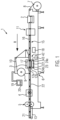
- Figure 1 shows a schematic view of a packaging machine 1, which can be a thermoforming packaging machine.
- the packaging machine 1 can have one or more work stations, in particular, as in the exemplary embodiment shown, a forming station 2, a sealing station 3, a cross-cutting device 4 and a longitudinal cutting device 5.
- the packaging machine can have one or more of the work stations mentioned. These can be arranged in the order mentioned in a working direction R on a machine frame 6.
- a leak detection station 11 can be arranged downstream of the forming station 2 as a further work station.
- a feed roller 7 can be provided on the machine frame 6, from which a first film 8 can be removed.
- a film storage 9 can be provided, from which a second film 10 can be removed as a cover film.
- a removal device 13 e.g. B. in the form of a conveyor belt, with which finished, isolated packaging can be transported away.
- the packaging machine 1 can have a feed device, not shown, which grips the first film 8 and preferably in one Main work cycle can be transported in cycles in the working direction R.
- the feed device can be implemented, for example, by laterally arranged transport chains, preferably clamp chains.
- the forming station 2 can be designed as a deep-drawing station.
- One or more packaging troughs 14 can be formed into the first film 8 by deep drawing.
- the forming station 2 can be designed in such a way that several packaging troughs can be formed next to one another in a direction perpendicular to the working direction R.
- An insertion section 15 can be provided behind the forming station 2 in the working direction R.
- There the packaging troughs 14 formed in the first film 8 can be filled with product 16.
- the sealing station 3 can include an upper tool 12a and a lower tool 12b. These can be configured to form a chamber 17 that can be closed in a gas-tight manner, in which an atmosphere in the packaging troughs 14 can be changed before sealing, for example by evacuation and/or by gas flushing with a replacement gas or with a replacement gas mixture.
- the chamber 17 can be closed, as in the present exemplary embodiment, by lifting the lower tool 12b and pressing it against the upper tool 12a.
- the sealing station 3 can include a hoist 42.
- This can contain a pressure source 43.
- the lifting gear 42 can further have a lifting actuator 22, which can include a hose 23 and a first closure 24a and preferably a second closure 24b.
- the pressure source 43 can supply the lifting actuator 22 with a working fluid.
- the working fluid can be filled into the hose 23 from the pressure source 43, preferably at a constant or variable pressure. This allows the hose 23 to increase its volume and thereby lift the lower tool 12b.
- the working fluid can be air.
- the pressure source can be a pump or a compressor, as shown here.
- the arrangement of the hoist 42 or the lifting actuator 22 is exemplary.
- the hoist 42 or the lifting actuator 22 can be provided in each of the work stations mentioned, in particular in one, several or all of the work stations mentioned.
- the hoist 42 or the lifting actuator 22 can be used to lift a component of a work station, e.g. B. the lower tool 12b and / or for pressing down a component of a workstation, e.g. B. the upper tool 12a, be configured.
- the cross-cutting device 4 can be designed as a punch, which can be set up to cut the first film 8 and the second film 10 in a direction transverse to the working direction R between adjacent packaging troughs 14.
- the cross-cutting device 4 can be configured in such a way that the first film 8 is not divided over the entire width, but is not cut through at least in an edge region. This can enable controlled further transport through the feed device.
- the longitudinal cutting device 5 can, as in the illustrated embodiment, be designed as a rotating circular knife arrangement with which the first film 8 and the second film 10 can be cut between adjacent packaging troughs 14 and on the lateral edge of the first film 8, whereby behind the longitudinal cutting device 5 isolated packaging may be present.
- the cross-cutting device 4 and the longitudinal cutting device 5 can each be viewed as a work station, in particular a cutting station, or can be viewed together as a work station, in particular a cutting station.
- the packaging machine 1 can also contain a control unit 18. It can be configured to control and/or monitor the processes occurring in the packaging machine 1.
- a display device 19 can preferably be provided with operating elements 20 and set up to visualize or influence process sequences in the packaging machine 1 for or by an operator.
- the general operation of the packaging machine 1 can be as briefly shown below.
- the first film 8 can be pulled off the feed roll 7 and transported into the forming station 2 by the feed device.
- one or more packaging troughs 14 can be formed in the first film 8 by deep drawing.
- the packaging troughs 14 can be transported step by step to the leakage detection station 11 together with the surrounding area of the first film 8 in a main work cycle. There they can be checked for leaks that may have occurred during molding, for example.
- the packaging troughs 14 can then be transported further to the insertion section 15, where they can be filled with product 16.
- the filled packaging troughs 14, together with the area of the first film 8 surrounding them, can then be transported further into the sealing station 3 by the feed device.
- the second film 10 can be attached to the sealing station 3 as a cover film first foil 8 is sealed.
- the second film 10 can then be transported further with the feed movement of the first film 8.
- the second film 10 can be removed from the film storage 9. By sealing the cover film 10 to the packaging troughs 14, closed packaging 21 can be created.
- the packaging 21 can be separated in the cutting devices 4, 5 by cutting the films 8, 10 in the transverse or longitudinal direction.
- a complete cutting device (not shown) can also be used, which can separate the packages 21 in one step.
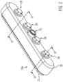
- Figure 2 shows a perspective view of the first closure 24a. Even if reference is made below to the first closure 24a, the explanations are also applicable to the second closure 24b.
- the first closure 24a can have a connection 25. This can be configured to direct a working fluid, in the present exemplary embodiment air, into and/or out of the hose 23 through the first closure 24a.
- the second closure 24b can also have a connection 25 or can be designed without such a connection.
- the first closure 24a contains a closure piece 26.
- the closure 24a also contains an insert 27.
- the closure piece 26 and the insert 27 can be screwed together.
- one or more screw connections 28 can be provided.
- Each of the screw connections 28 can, for example, include a screw 29 and a thread 30, which can be provided in the insert 27 (see Figure 3A ).
- Each of the screw connections 28 can pull the insert 27 and the closure piece 26 towards each other in a pulling direction.
- Figure 3A shows a schematic sectional view of the closure 24a in a perspective shown in Figure 2 is indicated by line III-III.
- the hose 23 can also be seen in this view. This is shown in a substantially emptied state.
- Figure 3B shows the view Figure 3A .
- the hose 23 is shown there in the filled state.
- the hose 23 can have a wall 31.
- the wall 31 can in turn have an outer surface 32. It can also have an inner surface 33.
- the insert 27 can engage with the inner surface 33 of the wall 31.
- the closure piece 26 can engage with the outer surface 32 of the wall 31.
- a clamping section 34 of the wall 31 can be clamped fluid-tight between the insert 27 and the closure piece 26.
- the wall 31 of the hose 23 can, on the one hand, extend in an axial direction L, which can be defined between the first and the second closure 24a, 24b. On the other hand, the wall 31 may extend in a circumferential direction (not shown).
- the first and second closures 24a, 24b can seal an interior 35 of the hose 23 in the axial direction L.
- the wall 31 of the hose 23 can seal the interior 35 in a variety of radial directions, each of which extends perpendicular to the axial direction L.
- the closure piece 26 can have a recess 36.
- the depression can have a bottom surface 37. It can also have an opening surface 38. It should be noted that the opening surface 38 itself is not a material surface, but is merely surrounded by the material of the closure piece 26.
- the recess 36 may also have a wall surface 39 which may extend between the bottom surface 37 and the opening surface 38.
- the opening surface 38 can have an area that is larger than the area of the bottom surface 37.
- the recess 36 can therefore be designed conically.
- Figure 4B also shows a sectional view, with the section as in Figure 2 indicated by line IV-IV.
- the insert 27 can have a conical part 40.
- the insert 27 can have a clamping surface 41.
- the clamping surface 41 and the wall surface 39 of the closure piece 26 can be coordinated with one another in such a way that the insert 27 can be inserted into the recess 36 of the closure piece 26.
- the clamping surface 41 can engage with the inner surface 33 of the wall 31 of the hose 23.
- first closure 24a all statements relating to the first closure 24a are also applicable to the second closure 24b. It should be noted that the second closure 24b can also be designed without a connection 25. Embodiments are also conceivable in which the first closure 24a does not have a connection 25, even if these are less preferred, as already explained above.
Description
Die Erfindung bezieht sich auf eine Arbeitsstation für eine Verpackungsmaschine gemäß dem Oberbegriff des Anspruchs 1 sowie auf eine Verpackungsmaschine mit einer solchen Arbeitsstation.The invention relates to a work station for a packaging machine according to the preamble of claim 1 and to a packaging machine with such a work station.
Aus der
Aus der
Es ist eine Aufgabe der Erfindung, eine bezüglich der genannten Nachteile verbesserte Arbeitsstation bzw. Verpackungsmaschine anzugeben. Diese Aufgabe wird gelöst durch eine Arbeitsstation gemäß dem Anspruch 1 sowie durch eine Verpackungsmaschine gemäß dem Anspruch 8. Vorteilhafte Weiterbildungen sind in den abhängigen Ansprüchen angegeben.It is an object of the invention to provide a work station or packaging machine that is improved with respect to the disadvantages mentioned. This task is solved by a work station according to claim 1 and by a packaging machine according to claim 8. Advantageous developments are specified in the dependent claims.
Die Erfindung sieht eine Arbeitsstation mit den Merkmalen des Anspruchs 1 für eine Verpackungsmaschine vor. Die Arbeitsstation weist ein Hubwerk mit einer Druckquelle und einem mit der Druckquelle verbundenen Hubaktor auf. Der Hubaktor umfasst einen Schlauch mit einer Wand, die eine innere Oberfläche und eine der inneren Oberfläche gegenüberliegende äußere Oberfläche aufweist, sowie einen Verschluss mit einem Verschlussstück, das mit der äußeren Oberfläche in Eingriff ist. Die Arbeitsstation zeichnet sich dadurch aus, dass der Verschluss des Weiteren einen Einsatz umfasst, der mit der inneren Oberfläche in Eingriff ist, wobei der Verschluss einen Klemmabschnitt der Wand des Schlauchs zwischen dem Einsatz und dem Verschlussstück fluiddicht, vorzugsweise gasdicht, klemmt.The invention provides a work station with the features of claim 1 for a packaging machine. The work station has a hoist with a pressure source and a lifting actuator connected to the pressure source. The lifting actuator includes a hose with a wall that has an inner surface and has an outer surface opposite the inner surface, and a closure with a closure piece that engages the outer surface. The work station is characterized in that the closure further comprises an insert which engages with the inner surface, the closure clamping a clamping portion of the wall of the hose between the insert and the closure piece in a fluid-tight, preferably gas-tight, manner.
Diese Konfiguration weist mehrere Vorteile auf. Zum Beispiel kann dadurch, dass der Einsatz mit der inneren Oberfläche in Eingriff kommt, eine Versorgung des Aktors mit einem Druckmedium durch den Verschluss hindurch ermöglicht werden, sodass auf eine durch die Wand des Schlauches verlaufende Druckmediumsversorgung verzichtet werden kann. Des Weiteren kann durch das Vorsehen des Einsatzes eine Hubhöhe des Hubaktors in der Nähe des Verschlusses erhöht werden.This configuration has several advantages. For example, the fact that the insert engages with the inner surface makes it possible to supply the actuator with a pressure medium through the closure, so that a pressure medium supply running through the wall of the hose can be dispensed with. Furthermore, by providing the insert, a lifting height of the lifting actuator in the vicinity of the closure can be increased.
Als Schlauch kann ein länglicher, flexibler Hohlkörper angesehen werden, der an gegenüberliegenden Enden Öffnungen aufweist. Eine Richtung entlang der länglichen Ausdehnung des Schlauches kann als axiale Richtung angesehen werden. Der Schlauch kann im Wesentlichen durch eine Wand des Schlauches gebildet sein. Diese kann einen Innenraum des Schlauches in radialen Richtungen begrenzen. Die radialen Richtungen können senkrecht zu der axialen Richtung des Schlauches definiert sein. Als Druckquelle können verschiedene Einrichtungen zur Druckerzeugung angesehen werden, z. B. eine Pumpe, ein Kompressor, eine zentrale Druckluftversorgung oder, falls die jeweilige Einrichtung nicht als Teil des Hubwerks sondern bspw. der Verpackungsmaschine vorgesehen ist, ein Anschluss des Hubwerks, der an eine der genannten Einrichtungen anschließbar ist.A hose can be viewed as an elongated, flexible hollow body that has openings at opposite ends. A direction along the elongate extent of the tube can be considered an axial direction. The hose can essentially be formed by a wall of the hose. This can limit an interior space of the hose in radial directions. The radial directions can be defined perpendicular to the axial direction of the tube. Various devices for generating pressure can be viewed as a pressure source, e.g. B. a pump, a compressor, a central compressed air supply or, if the respective device is not provided as part of the hoist but, for example, the packaging machine, a connection of the hoist that can be connected to one of the devices mentioned.
In axialer Richtung kann der Innenraum des Schlauches durch die gegenüberliegenden Öffnungen zugänglich sein. Um einen gegenüber der Umgebung des Schlauches abgedichteten Raum zu erzeugen, müssen die gegenüberliegenden Öffnungen dicht verschlossen werden. Dies kann erfindungsgemäß bei mindestens einer Öffnung durch den Verschluss erfolgen. Es können auch beide Öffnungen durch jeweils einen Verschluss gasdicht verschlossen sein. Alternativ kann eine der Öffnungen z. B. gasdicht vernäht sein. Insbesondere kann die Wand des Schlauches den Innenraum des Schlauches in radialen Richtungen begrenzen und der Verschluss kann den Innenraum des Schlauches in axialer Richtung begrenzen.In the axial direction, the interior of the hose can be accessible through the opposite openings. In order to create a space that is sealed from the surroundings of the hose, the opposite openings must be tightly closed. According to the invention, this can be done with at least one opening through the closure. Both openings can also be closed in a gas-tight manner by a closure. Alternatively, one of the openings can e.g. B. be sewn gas-tight. In particular, the wall of the hose can limit the interior of the hose in radial directions and the closure can limit the interior of the hose in axial directions.
Es ist denkbar, dass das Verschlussstück eine Vertiefung aufweist, in die der Einsatz einsetzbar ist. Vorzugsweise erstreckt sich die Vertiefung in axialer Richtung, wenn der Verschluss den Klemmabschnitt der Wand klemmt. Dadurch kann ermöglicht werden, dass die Wand des Schlauches in radialer Richtung an eine Seitenwand der Vertiefung angedrückt wird, insbesondere durch den Einsatz.It is conceivable that the closure piece has a recess into which the insert can be inserted. Preferably, the recess extends in the axial direction when the closure clamps the clamping portion of the wall. This makes it possible for the wall of the hose to be pressed in the radial direction against a side wall of the recess, in particular by the insert.
Es ist vorteilhaft, wenn eine Öffnungsfläche der Vertiefung einen größeren Flächeninhalt aufweist als eine Bodenfläche der Vertiefung. Dies kann ein Einführen des Klemmabschnitts der Wand des Schlauchs in die Vertiefung erleichtern.It is advantageous if an opening area of the recess has a larger surface area than a bottom area of the recess. This can facilitate insertion of the clamping portion of the wall of the hose into the recess.
Der Einsatz weist einen konischen Teil auf. Dadurch kann eine besonders effektive Klemmung erreicht werden. Besonders günstig ist es, wenn der gesamte Einsatz konisch ausgeführt ist.The insert has a conical part. This allows particularly effective clamping to be achieved. It is particularly favorable if the entire insert is conical.
Vorzugsweise weist der Verschluss einen Anschluss auf, der dazu konfiguriert ist, ein Arbeitsfluid, vorzugsweise ein Gas, besonders bevorzugt Luft, durch den Verschluss in den Schlauch und/oder aus diesem herauszuleiten. Wie bereits angedeutet, kann dadurch auf eine Druckmediumsversorgung, die durch die Wand des Schlauches hindurch verläuft, verzichtet werden. Dies ist vorteilhaft, da so die abzudichtenden Öffnungen auf die beiden Endöffnungen an den gegenüberliegenden Enden des Schlauches begrenzt werden kann. Außerdem entfällt die Notwendigkeit, an den am Schlauch anliegenden Oberflächen der anzuhebenden Komponenten Vorkehrungen, wie z. B. Aussparungen, für Druckmediumsanschlüsse vorzusehen.Preferably, the closure has a connection which is configured to direct a working fluid, preferably a gas, particularly preferably air, through the closure into and/or out of the hose. As already indicated, this means that there is no need for a pressure medium supply that runs through the wall of the hose. This is advantageous because the openings to be sealed can be limited to the two end openings at the opposite ends of the hose. In addition, there is no need to take precautions on the surfaces of the components to be lifted that are in contact with the hose, such as: B. Recesses to be provided for pressure medium connections.
Der Einsatz und das Verschlussstück sind miteinander verschraubbar. Dies kann eine besonders einfache und einfach zu realisierende Art, die Klemmung zu erreichen, ermöglichen. Gleichzeitig kann eine gute Dosierbarkeit der Klemmkraft gewährleistet werden.The insert and the closure piece can be screwed together. This can enable a particularly simple and easy-to-implement way of achieving the clamping. At the same time, good control of the clamping force can be guaranteed.
Es ist denkbar, dass eine Zugrichtung einer Verschraubung zum Verschrauben des Verschlussstücks mit dem Einsatz in einem Winkel zu einer Hubrichtung des Hubaktors orientiert ist, wobei der Winkel größer als 0° vorzugsweise größer als 45°, besonders bevorzugt 90° ist.It is conceivable that a pulling direction of a screw connection for screwing the closure piece to the insert is oriented at an angle to a lifting direction of the lifting actuator, the angle being greater than 0°, preferably greater than 45°, particularly preferably 90°.
In einer weiteren Variante können zwei Verschlüsse an gegenüberliegenden Abschnitten des Schlauchs vorgesehen sein. Auf diese Weise können die mit Bezug auf den Verschluss erläuterten Vorteile an beiden Enden des Schlauches erreicht werden. Ein Anschluss, wie er bereits weiter oben erläutert wurde, kann an einem oder beiden oder keinem der Verschlüsse vorgesehen sein. Ein Hubaktor mit zwei Verschlüssen mit jeweils einem Anschluss kann den Vorteil aufweisen, dass ein Arbeitsfluid gleichmäßiger eingefüllt und/oder abgelassen werden kann. Dadurch kann ein Kippen der anzuhebenden Komponente vermieden werden.In a further variant, two closures can be provided on opposite sections of the hose. In this way, the advantages explained with reference to the closure can be achieved at both ends of the hose. A connection, as already explained above, can be provided on one or both or neither of the closures. A lifting actuator with two closures, each with a connection, can have the advantage that a working fluid can be filled and/or drained more evenly. This can prevent the component being lifted from tipping over.
Die Arbeitsstation kann z. B. eine Siegelstation oder eine Schneidstation oder eine Formstation sein.The workstation can e.g. B. be a sealing station or a cutting station or a forming station.
Die Erfindung bezieht sich auch auf eine Verpackungsmaschine mit einer Arbeitsstation gemäß einem der vorangehenden Ansprüche.The invention also relates to a packaging machine with a work station according to one of the preceding claims.
Die Erfindung bezieht sich auf eine Arbeitsstation sowie eine Verpackungsmaschine der vorstehend beschriebenen Art. Im Folgenden wird ein vorteilhaftes Ausführungsbeispiel anhand von Zeichnungen näher erläutert.
- Figur 1
- zeigt eine schematische Seitenansicht einer Verpackungsmaschine.
- Figur 2
- zeigt eine perspektivische Ansicht eines Verschlusses eines Hubaktors.
- Figur 3A
- zeigt eine schematische Schnittansicht des Verschlusses, wobei die Schnittebene wie in
Figur 2 durch die Linie III-III angedeutet verläuft. - Figur 3B
- zeigt die Ansicht aus
Figur 3A , wobei der Hubaktor im aufgeblasenen Zustand dargestellt ist. - Figur 4A
- zeigt eine schematische Schnittansicht eines Verschlussstücks des Verschlusses, wobei die Schnittebene wie in
Figur 2 durch die Linie IV-IV angedeutet verläuft. - Figur 4B
- zeigt eine schematische Schnittansicht eines Einsatzes des Verschlusses, wobei die Schnittebene wie in
Figur 2 durch die Linie IV-IV angedeutet verläuft.
- Figure 1
- shows a schematic side view of a packaging machine.
- Figure 2
- shows a perspective view of a closure of a lifting actuator.
- Figure 3A
- shows a schematic sectional view of the closure, with the cutting plane as in
Figure 2 indicated by line III-III. - Figure 3B
- shows the view
Figure 3A , with the lifting actuator shown in the inflated state. - Figure 4A
- shows a schematic sectional view of a closure piece of the closure, with the cutting plane as in
Figure 2 indicated by line IV-IV. - Figure 4B
- shows a schematic sectional view of an insert of the closure, with the cutting plane as in
Figure 2 indicated by line IV-IV.
Eingangsseitig kann an dem Maschinengestell 6 eine Zufuhrrolle 7 vorgesehen sein, von der eine erste Folie 8 abgezogen werden kann. Im Bereich der Siegelstation 3 kann ein Folienspeicher 9 vorgesehen sein, von dem eine zweite Folie 10 als Deckelfolie abgezogen werden kann. Ausgangsseitig kann an der Verpackungsmaschine eine Abfuhreinrichtung 13, z. B. in Form eines Transportbandes, vorgesehen sein, mit der fertige, vereinzelte Verpackungen abtransportiert werden können. Ferner kann die Verpackungsmaschine 1 eine nicht dargestellte Vorschubeinrichtung aufweisen, welche die erste Folie 8 ergreifen und vorzugsweise in einem Hauptarbeitstakt taktweise in der Arbeitsrichtung R weitertransportieren kann. Die Vorschubeinrichtung kann zum Beispiel durch seitlich angeordnete Transportketten, vorzugsweise Klammerketten, realisiert sein.On the input side, a feed roller 7 can be provided on the
Wie in der dargestellten Ausführungsform gezeigt, kann die Formstation 2 als eine Tiefziehstation ausgebildet sein. Darin können durch Tiefziehen eine oder mehrere Verpackungsmulden 14 in die erste Folie 8 geformt werden. Dabei kann die Formstation 2 derart ausgebildet sein, dass in einer Richtung senkrecht zur Arbeitsrichtung R mehrere Verpackungsmulden nebeneinander gebildet werden können. In Arbeitsrichtung R hinter der Formstation 2 kann eine Einlegestrecke 15 vorgesehen sein. Dort können die in die erste Folie 8 geformten Verpackungsmulden 14 mit Produkt 16 befüllt werden.As shown in the illustrated embodiment, the forming station 2 can be designed as a deep-drawing station. One or more packaging troughs 14 can be formed into the first film 8 by deep drawing. The forming station 2 can be designed in such a way that several packaging troughs can be formed next to one another in a direction perpendicular to the working direction R.
Die Siegelstation 3 kann ein Oberwerkzeug 12a und ein Unterwerkzeug 12b umfassen. Diese können dazu konfiguriert sein, eine gasdicht verschließbare, Kammer 17 zu bilden, in der eine Atmosphäre in den Verpackungsmulden 14 vor dem Versiegeln verändert werden kann, zum Beispiel durch Evakuieren und/oder durch Gasspülen mit einem Austauschgas oder mit einem Austausch-Gasgemisch. Das Schließen der Kammer 17 kann, wie im vorliegenden Ausführungsbeispiel, durch Anheben des Unterwerkzeugs 12b und Andrücken an das Oberwerkzeug 12a erfolgen.The sealing
Dazu kann die Siegelstation 3 ein Hubwerk 42 umfassen. Dieses kann eine Druckquelle 43 enthalten. Das Hubwerk 42 kann des Weiteren einen Hubaktor 22 aufweisen, der einen Schlauch 23 und einen ersten Verschluss 24a und vorzugsweise einen zweiten Verschluss 24b umfassen kann. Die Druckquelle 43 kann den Hubaktor 22 mit einem Arbeitsfluid versorgen. Das Arbeitsfluid kann von der Druckquelle 43, vorzugsweise mit einem konstanten oder variablen Druck, in den Schlauch 23 eingefüllt werden. Dadurch kann der Schlauch 23 sein Volumen vergrößern, und dadurch das Unterwerkzeug 12b anheben. Wie im vorliegenden Ausführungsbeispiel, kann es sich bei dem Arbeitsfluid um Luft handeln. Bei der Druckquelle kann es sich, wie hier dargestellt, um eine Pumpe oder einen Kompressor handlen.For this purpose, the sealing
Es ist zu beachten, dass die Anordnung des Hubwerks 42 bzw. des Hubaktors 22 beispielhaft ist. Das Hubwerk 42 bzw. der Hubaktor 22 kann in jeder der genannten Arbeitsstationen vorgesehen sein, insbesondere in einer, mehreren oder allen der genannten Arbeitsstationen. Des Weiteren kann das Hubwerk 42 bzw. der Hubaktor 22 zum Anheben einer Komponente einer Arbeitsstation, z. B. des Unterwerkzeugs 12b und/oder zum Herunterdrücken einer Komponente einer Arbeitsstaion, z. B. des Oberwerkzeugs 12a, konfiguriert sein.It should be noted that the arrangement of the hoist 42 or the lifting
Die Querschneideinrichtung 4 kann als Stanze ausgebildet sein, welche dazu eingerichtet sein kann, die erste Folie 8 und die zweite Folie 10 in einer Richtung quer zur Arbeitsrichtung R zwischen benachbarten Verpackungsmulden 14 zu durchtrennen. Dabei kann die Querschneideinrichtung 4 derart konfiguriert sein, dass die erste Folie 8 nicht über die gesamte Breite aufgeteilt wird, sondern zumindest in einem Randbereich nicht durchtrennt wird. Dies kann einen kontrollierten Weitertransport durch die Vorschubeinrichtung ermöglichen.The
Die Längsschneideinrichtung 5 kann, wie in der dargestellten Ausführungsform, als eine rotierende Rundmesseranordnung ausgebildet sein, mit der die erste Folie 8 und die zweite Folie 10 zwischen benachbarten Verpackungsmulden 14 und am seitlichen Rand der ersten Folie 8 durchtrennt werden kann, wodurch hinter der Längsschneideinrichtung 5 vereinzelte Verpackungen vorliegen können. Die Querschneideinrichtung 4 und die Längsschneideinrichtung 5 können jeweils als eine Arbeitsstation, insbesondere eine Schneidstation, angesehen werden oder zusammen als eine Arbeitsstation, insbesondere eine Schneidstation, angesehen werden.The longitudinal cutting device 5 can, as in the illustrated embodiment, be designed as a rotating circular knife arrangement with which the first film 8 and the
Die Verpackungsmaschine 1 kann ferner eine Steuereinheit 18 enthalten. Sie kann dazu konfiguriert sein, die in der Verpackungsmaschine 1 ablaufenden Prozesse zu steuern und/oder zu überwachen. Außerdem kann eine Anzeigevorrichtung 19 vorzugsweise mit Bedienelementen 20 vorgesehen und dazu eingerichtet sein, Prozessabläufe in der Verpackungsmaschine 1 für bzw. durch einen Bediener zu visualisieren bzw. zu beeinflussen.The packaging machine 1 can also contain a
Die generelle Arbeitsweise der Verpackungsmaschine 1 kann wie im Folgenden kurz dargestellt ablaufen.The general operation of the packaging machine 1 can be as briefly shown below.
Die erste Folie 8 kann von der Zufuhrrolle 7 abgezogen und durch die Vorschubeinrichtung in die Formstation 2 transportiert werden. In der Formstation 2 können durch Tiefziehen eine oder mehrere Verpackungsmulden 14 in der ersten Folie 8 gebildet werden. Die Verpackungsmulden 14 können zusammen mit dem umgebenden Bereich der ersten Folie 8 in einem Hauptarbeitstakt schrittweise zu der Leckageerkennungsstation 11 weitertransportiert werden. Dort können sie auf Leckagen geprüft werden, die z.B. beim Formen aufgetreten sein können. Anschließend können die Verpackungsmulden 14 zu der Einlegestrecke 15 weitertransportiert werden, wo sie mit Produkt 16 befüllt werden können.The first film 8 can be pulled off the feed roll 7 and transported into the forming station 2 by the feed device. In the forming station 2, one or more packaging troughs 14 can be formed in the first film 8 by deep drawing. The packaging troughs 14 can be transported step by step to the
Anschließend können die befüllten Verpackungsmulden 14 zusammen mit dem sie umgebenden Bereich der ersten Folie 8 durch die Vorschubeinrichtung in die Siegelstation 3 weitertransportiert werden. Die zweite Folie 10 kann in der Siegelstation 3 als Deckelfolie an die erste Folie 8 angesiegelt werden. Danach kann die zweite Folie 10 mit der Vorschubbewegung der ersten Folie 8 weitertransportiert werden. Dabei kann die zweite Folie 10 von dem Folienspeicher 9 abgezogen werden. Durch das Ansiegeln der Deckelfolie 10 an die Verpackungsmulden 14 können verschlossene Verpackungen 21 entstehen.The filled packaging troughs 14, together with the area of the first film 8 surrounding them, can then be transported further into the sealing
In den Schneideinrichtungen 4, 5 können die Verpackungen 21 vereinzelt werden, indem die Folien 8, 10 in Quer- bzw. Längsrichtung durchtrennt werden. Zum Vereinzeln kann anstelle der Schneidvorrichtungen 4, 5 auch eine Komplettschnittvorrichtung (nicht gezeigt) eingesetzt werden, welche die Verpackungen 21 in einem Schritt vereinzeln kann.The
Der erste Verschluss 24a enthält ein Verschlussstück 26 . Der Verschluss 24a enthält des Weiteren einen Einsatz 27. Das Verschlussstück 26 und der Einsatz 27 sind miteinander verschraubbar. Dazu können eine oder mehrere Verschraubungen 28 vorgesehen sein. Jede der Verschraubungen 28 kann zum Beispiel eine Schraube 29 und ein Gewinde 30 umfassen, welches in dem Einsatz 27 vorgesehen sein kann (siehe
Die Wand 31 des Schlauches 23 kann sich zum Einen in einer axialen Richtung L erstrecken die zwischen dem ersten und dem zweiten Verschluss 24a, 24b definiert sein kann. Die Wand 31 kann sich zum Anderen in einer Umfangsrichtung (nicht dargestellt) erstrecken. Der erste und der zweite Verschluss 24a, 24b können einen Innenraum 35 des Schlauches 23 in der axialen Richtung L abdichten. Die Wand 31 des Schlauches 23 kann den Innenraum 35 in einer Vielzahl von radialen Richtungen, die sich jeweils senkrecht zur axialen Richtung L erstrecken, abdichten. Durch Befüllen des Schlauches 23 kann durch dessen Expansion eine anzuhebende Komponente, wie im vorliegenden Ausführungsbeispiel des Unterwerkzeugs 12b, in einer Hubrichtung H angehoben werden.The
In
Wie bereits angedeutet, sind alle Ausführungen mit Bezug auf den ersten Verschluss 24a auch auf den zweiten Verschluss 24b anwendbar. Dabei ist zu beachten, dass der zweite Verschluss 24b auch ohne einen Anschluss 25 ausgeführt sein kann. Es sind ebenfalls Ausführungsbeispiele denkbar, in denen auch der erste Verschluss 24a keinen Anschluss 25 aufweist, auch wenn diese wie bereits weiter oben erläutert, weniger bevorzugt sind.As already indicated, all statements relating to the
Claims (8)
- Working station (2, 3, 4, 5, 11) for a packaging machine (1), wherein the working station (2, 3, 4, 5, 11) has a lifting unit (42) having a pressure source (43) and a lifting actuator (22) connected to the pressure source (43) and wherein the lifting actuator (22) comprises:a hose (23) comprising a wall (31) having an inner surface (33) and an outer surface (32) disposed opposite the inner surface (33),a seal (24a, 24b) having a seal cap (26) engaging the outer surface (32), and an insert (27) engaging the inner surface (33), wherein the seal (24a, 24b) clamps a clamping portion (34) of the wall (31) of the hose (23) between the insert (27) and the seal cap (26) in a fluidtight, preferably gastight, manner, and wherein the insert (27) and the seal cap (26) are screwable to one anothercharacterized in that the insert (27) has a tapered portion (40).
- Working station according to claim 1, wherein the seal cap (26) has a recess (36), in which the insert (27) is insertable.
- Working station according to claim 2, wherein an opening plane (38) of the recess (36) has a larger area than a bottom surface (37) of the recess (36).
- Working station according to one of the preceding claims, wherein the seal (24a, 24b) has a connector (25), which is configured to conduct a working fluid, preferably a gas, through the seal (24a, 24b) into the hose (23) and/or out if the hose (23).
- Working station according to one of the preceding claims, wherein a pulling direction of a screw connection (28) for screwing the seal cap (26) to the insert (27) is oriented in an angle with respect to a lifting direction (H) of the lifting actuator (22), wherein the angel is larger than 0°, preferably larger than 45°, particularly preferred larger than 90°.
- Working station according to one of the preceding claims, wherein two seals (24a, 24b) are provided on opposite sections of the hose (23).
- Working station according to one of the preceding claims, wherein the working station (2, 3, 4, 5, 11) is a sealing station (3) or a cutting station (4, 5,) or a forming station (2).
- Packaging machine (1) having a working station (2, 3, 4, 5, 11) according to one of the preceding claims.
Applications Claiming Priority (1)
| Application Number | Priority Date | Filing Date | Title |
|---|---|---|---|
| DE102019210728.1A DE102019210728A1 (en) | 2019-07-19 | 2019-07-19 | Workstation for a packaging machine |
Publications (2)
| Publication Number | Publication Date |
|---|---|
| EP3766680A1 EP3766680A1 (en) | 2021-01-20 |
| EP3766680B1 true EP3766680B1 (en) | 2023-09-13 |
Family
ID=71575007
Family Applications (1)
| Application Number | Title | Priority Date | Filing Date |
|---|---|---|---|
| EP20184953.6A Active EP3766680B1 (en) | 2019-07-19 | 2020-07-09 | Work station for a packing machine |
Country Status (5)
| Country | Link |
|---|---|
| US (1) | US11279507B2 (en) |
| EP (1) | EP3766680B1 (en) |
| CN (1) | CN213705951U (en) |
| DE (1) | DE102019210728A1 (en) |
| ES (1) | ES2962437T3 (en) |
Family Cites Families (14)
| Publication number | Priority date | Publication date | Assignee | Title |
|---|---|---|---|---|
| US2877801A (en) * | 1954-11-02 | 1959-03-17 | Greer Hydraulics Inc | Clamping means for bladder of pressure accumulator |
| US3121577A (en) * | 1960-04-25 | 1964-02-18 | Henry H Merriman | Inflatable tube hose fitting |
| US4178015A (en) * | 1977-12-12 | 1979-12-11 | Merriman Products, Inc. | Inflated vehicle spring and lift |
| US4513997A (en) * | 1982-09-30 | 1985-04-30 | Greenco Corporation | Fitting for an inflatable tube |
| EP0115199A1 (en) * | 1982-12-27 | 1984-08-08 | William O. Holmes | Hydraulic jack and method for making the same |
| US5205110C1 (en) * | 1990-12-12 | 2001-05-15 | Dec Int | Servo motor operated indexing motion packaging machine and method |
| SE506711C2 (en) * | 1993-05-03 | 1998-02-02 | Svante Borg | Container |
| DE102006049067A1 (en) * | 2006-10-13 | 2008-04-17 | Cfs Germany Gmbh | Packaging machine with a pneumatic muscle |
| US8499536B2 (en) * | 2009-05-18 | 2013-08-06 | Alkar-Rapidpak-Mp Equipment, Inc. | Apparatuses and methods for assisted tooling extraction |
| DE102010009536A1 (en) * | 2010-02-26 | 2011-09-01 | Cfs Germany Gmbh | Method for changing the upper and lower tool of a packaging machine |
| DE102012003830A1 (en) * | 2012-02-29 | 2013-08-29 | Gea Cfs Germany Gmbh | Packaging machine with a replaceable tool |
| CA3051615C (en) * | 2015-05-15 | 2021-06-01 | Usnr/Kockums Cancar Company | Modular press |
| US10507626B2 (en) * | 2016-05-16 | 2019-12-17 | Alkar-Rapidpak, Inc. | Bladder devices for moving components of web packaging machines |
| DE102018205891B3 (en) * | 2018-04-18 | 2019-02-21 | Festo Ag & Co. Kg | Activatable by Fluidbeaufschlagung actuator with locking mechanism |
-
2019
- 2019-07-19 DE DE102019210728.1A patent/DE102019210728A1/en active Pending
-
2020
- 2020-07-09 EP EP20184953.6A patent/EP3766680B1/en active Active
- 2020-07-09 ES ES20184953T patent/ES2962437T3/en active Active
- 2020-07-16 US US16/931,023 patent/US11279507B2/en active Active
- 2020-07-17 CN CN202021414463.XU patent/CN213705951U/en active Active
Also Published As
| Publication number | Publication date |
|---|---|
| EP3766680A1 (en) | 2021-01-20 |
| US11279507B2 (en) | 2022-03-22 |
| DE102019210728A1 (en) | 2021-01-21 |
| CN213705951U (en) | 2021-07-16 |
| US20210016911A1 (en) | 2021-01-21 |
| ES2962437T3 (en) | 2024-03-19 |
Similar Documents
| Publication | Publication Date | Title |
|---|---|---|
| DE4205655C2 (en) | Method for sterilizing a packaging machine and device for carrying out the method | |
| DE2430497A1 (en) | DEVICE FOR PACKAGING GOODS | |
| EP2495173B1 (en) | Method and device for filling valve sacks with bulk goods | |
| DE2838506A1 (en) | METHOD AND DEVICE FOR MANUFACTURING BLISTERS WITH HIGH LOCKING EFFECT | |
| WO2013050968A1 (en) | Method for draining or filling a vessel while avoiding contamination | |
| EP3766680B1 (en) | Work station for a packing machine | |
| EP1361380B1 (en) | Sealing arrangement | |
| EP3428080B1 (en) | Connection device | |
| DE102013105755B4 (en) | Opening device for opening a bag section of a film web in a bag filling system | |
| DE3411917A1 (en) | METHOD AND DEVICE FOR PACKING OBJECTS | |
| DE3044550C2 (en) | Method and device for checking the leakage of disposable syringes | |
| DE202014101589U1 (en) | packaging machine | |
| EP3127826B1 (en) | Nozzle for inflating a spout film bag and method for inflating a spout film bag | |
| EP3831500A1 (en) | Docking device, valve device and dosing device and container | |
| WO2015169830A1 (en) | Packaging machine with vacuum control module consisting of uniform valve blocks | |
| DE102008001752A1 (en) | Filling device and method for filling containers | |
| DE102008039158B4 (en) | Device for sealing packages | |
| DE19510555A1 (en) | Sterilising process for components of packing machine | |
| EP3733528B1 (en) | Sealing tool and method for sealing trays | |
| WO2019002461A2 (en) | Device for the treatment of a container in a product filling system | |
| DE1997665U (en) | DEVICE FOR MANUFACTURING PACKAGING CONTAINERS | |
| DE2409716A1 (en) | Implosion chamber evacuation process - uses high-pressure chamber sealed from atmosphere containing implosion chamber at atmosphere pressure | |
| DE4405151C2 (en) | Filling machine for filling and subsequent closing of open sacks, especially large plastic sacks | |
| DE10009990A1 (en) | Method and device for filling double-walled containers | |
| DE202007004627U1 (en) | Internal high pressure molding system has retaining unit which exerts force on molding tool to hold it in place during molding |
Legal Events
| Date | Code | Title | Description |
|---|---|---|---|
| PUAI | Public reference made under article 153(3) epc to a published international application that has entered the european phase |
Free format text: ORIGINAL CODE: 0009012 |
|
| STAA | Information on the status of an ep patent application or granted ep patent |
Free format text: STATUS: THE APPLICATION HAS BEEN PUBLISHED |
|
| AK | Designated contracting states |
Kind code of ref document: A1 Designated state(s): AL AT BE BG CH CY CZ DE DK EE ES FI FR GB GR HR HU IE IS IT LI LT LU LV MC MK MT NL NO PL PT RO RS SE SI SK SM TR |
|
| AX | Request for extension of the european patent |
Extension state: BA ME |
|
| STAA | Information on the status of an ep patent application or granted ep patent |
Free format text: STATUS: REQUEST FOR EXAMINATION WAS MADE |
|
| 17P | Request for examination filed |
Effective date: 20210720 |
|
| RBV | Designated contracting states (corrected) |
Designated state(s): AL AT BE BG CH CY CZ DE DK EE ES FI FR GB GR HR HU IE IS IT LI LT LU LV MC MK MT NL NO PL PT RO RS SE SI SK SM TR |
|
| GRAP | Despatch of communication of intention to grant a patent |
Free format text: ORIGINAL CODE: EPIDOSNIGR1 |
|
| STAA | Information on the status of an ep patent application or granted ep patent |
Free format text: STATUS: GRANT OF PATENT IS INTENDED |
|
| RIC1 | Information provided on ipc code assigned before grant |
Ipc: F16L 55/115 20060101ALI20230317BHEP Ipc: B66F 3/35 20060101ALI20230317BHEP Ipc: F15B 15/10 20060101ALI20230317BHEP Ipc: F16L 33/02 20060101ALI20230317BHEP Ipc: B30B 5/02 20060101AFI20230317BHEP |
|
| INTG | Intention to grant announced |
Effective date: 20230404 |
|
| GRAS | Grant fee paid |
Free format text: ORIGINAL CODE: EPIDOSNIGR3 |
|
| GRAA | (expected) grant |
Free format text: ORIGINAL CODE: 0009210 |
|
| STAA | Information on the status of an ep patent application or granted ep patent |
Free format text: STATUS: THE PATENT HAS BEEN GRANTED |
|
| P01 | Opt-out of the competence of the unified patent court (upc) registered |
Effective date: 20230801 |
|
| AK | Designated contracting states |
Kind code of ref document: B1 Designated state(s): AL AT BE BG CH CY CZ DE DK EE ES FI FR GB GR HR HU IE IS IT LI LT LU LV MC MK MT NL NO PL PT RO RS SE SI SK SM TR |
|
| REG | Reference to a national code |
Ref country code: CH Ref legal event code: EP |
|
| REG | Reference to a national code |
Ref country code: DE Ref legal event code: R096 Ref document number: 502020005205 Country of ref document: DE |
|
| REG | Reference to a national code |
Ref country code: NL Ref legal event code: FP Ref country code: IE Ref legal event code: FG4D Free format text: LANGUAGE OF EP DOCUMENT: GERMAN |
|
| REG | Reference to a national code |
Ref country code: LT Ref legal event code: MG9D |
|
| PG25 | Lapsed in a contracting state [announced via postgrant information from national office to epo] |
Ref country code: GR Free format text: LAPSE BECAUSE OF FAILURE TO SUBMIT A TRANSLATION OF THE DESCRIPTION OR TO PAY THE FEE WITHIN THE PRESCRIBED TIME-LIMIT Effective date: 20231214 |
|
| PG25 | Lapsed in a contracting state [announced via postgrant information from national office to epo] |
Ref country code: SE Free format text: LAPSE BECAUSE OF FAILURE TO SUBMIT A TRANSLATION OF THE DESCRIPTION OR TO PAY THE FEE WITHIN THE PRESCRIBED TIME-LIMIT Effective date: 20230913 Ref country code: RS Free format text: LAPSE BECAUSE OF FAILURE TO SUBMIT A TRANSLATION OF THE DESCRIPTION OR TO PAY THE FEE WITHIN THE PRESCRIBED TIME-LIMIT Effective date: 20230913 Ref country code: NO Free format text: LAPSE BECAUSE OF FAILURE TO SUBMIT A TRANSLATION OF THE DESCRIPTION OR TO PAY THE FEE WITHIN THE PRESCRIBED TIME-LIMIT Effective date: 20231213 Ref country code: LV Free format text: LAPSE BECAUSE OF FAILURE TO SUBMIT A TRANSLATION OF THE DESCRIPTION OR TO PAY THE FEE WITHIN THE PRESCRIBED TIME-LIMIT Effective date: 20230913 Ref country code: LT Free format text: LAPSE BECAUSE OF FAILURE TO SUBMIT A TRANSLATION OF THE DESCRIPTION OR TO PAY THE FEE WITHIN THE PRESCRIBED TIME-LIMIT Effective date: 20230913 Ref country code: HR Free format text: LAPSE BECAUSE OF FAILURE TO SUBMIT A TRANSLATION OF THE DESCRIPTION OR TO PAY THE FEE WITHIN THE PRESCRIBED TIME-LIMIT Effective date: 20230913 Ref country code: GR Free format text: LAPSE BECAUSE OF FAILURE TO SUBMIT A TRANSLATION OF THE DESCRIPTION OR TO PAY THE FEE WITHIN THE PRESCRIBED TIME-LIMIT Effective date: 20231214 Ref country code: FI Free format text: LAPSE BECAUSE OF FAILURE TO SUBMIT A TRANSLATION OF THE DESCRIPTION OR TO PAY THE FEE WITHIN THE PRESCRIBED TIME-LIMIT Effective date: 20230913 |
|
| REG | Reference to a national code |
Ref country code: ES Ref legal event code: FG2A Ref document number: 2962437 Country of ref document: ES Kind code of ref document: T3 Effective date: 20240319 |
|
| PG25 | Lapsed in a contracting state [announced via postgrant information from national office to epo] |
Ref country code: IS Free format text: LAPSE BECAUSE OF FAILURE TO SUBMIT A TRANSLATION OF THE DESCRIPTION OR TO PAY THE FEE WITHIN THE PRESCRIBED TIME-LIMIT Effective date: 20240113 |