EP1361380B1 - Sealing arrangement - Google Patents
Sealing arrangement Download PDFInfo
- Publication number
- EP1361380B1 EP1361380B1 EP20030004049 EP03004049A EP1361380B1 EP 1361380 B1 EP1361380 B1 EP 1361380B1 EP 20030004049 EP20030004049 EP 20030004049 EP 03004049 A EP03004049 A EP 03004049A EP 1361380 B1 EP1361380 B1 EP 1361380B1
- Authority
- EP
- European Patent Office
- Prior art keywords
- sealing arrangement
- tube
- gap
- hose
- arrangement according
- Prior art date
- Legal status (The legal status is an assumption and is not a legal conclusion. Google has not performed a legal analysis and makes no representation as to the accuracy of the status listed.)
- Expired - Lifetime
Links
Images
Classifications
-
- B—PERFORMING OPERATIONS; TRANSPORTING
- B29—WORKING OF PLASTICS; WORKING OF SUBSTANCES IN A PLASTIC STATE IN GENERAL
- B29C—SHAPING OR JOINING OF PLASTICS; SHAPING OF MATERIAL IN A PLASTIC STATE, NOT OTHERWISE PROVIDED FOR; AFTER-TREATMENT OF THE SHAPED PRODUCTS, e.g. REPAIRING
- B29C33/00—Moulds or cores; Details thereof or accessories therefor
- B29C33/0038—Moulds or cores; Details thereof or accessories therefor with sealing means or the like
-
- B—PERFORMING OPERATIONS; TRANSPORTING
- B29—WORKING OF PLASTICS; WORKING OF SUBSTANCES IN A PLASTIC STATE IN GENERAL
- B29C—SHAPING OR JOINING OF PLASTICS; SHAPING OF MATERIAL IN A PLASTIC STATE, NOT OTHERWISE PROVIDED FOR; AFTER-TREATMENT OF THE SHAPED PRODUCTS, e.g. REPAIRING
- B29C44/00—Shaping by internal pressure generated in the material, e.g. swelling or foaming ; Producing porous or cellular expanded plastics articles
- B29C44/34—Auxiliary operations
- B29C44/35—Component parts; Details or accessories
- B29C44/351—Means for preventing foam to leak out from the foaming device during foaming
-
- F—MECHANICAL ENGINEERING; LIGHTING; HEATING; WEAPONS; BLASTING
- F16—ENGINEERING ELEMENTS AND UNITS; GENERAL MEASURES FOR PRODUCING AND MAINTAINING EFFECTIVE FUNCTIONING OF MACHINES OR INSTALLATIONS; THERMAL INSULATION IN GENERAL
- F16J—PISTONS; CYLINDERS; SEALINGS
- F16J15/00—Sealings
- F16J15/46—Sealings with packing ring expanded or pressed into place by fluid pressure, e.g. inflatable packings
-
- B—PERFORMING OPERATIONS; TRANSPORTING
- B29—WORKING OF PLASTICS; WORKING OF SUBSTANCES IN A PLASTIC STATE IN GENERAL
- B29K—INDEXING SCHEME ASSOCIATED WITH SUBCLASSES B29B, B29C OR B29D, RELATING TO MOULDING MATERIALS OR TO MATERIALS FOR MOULDS, REINFORCEMENTS, FILLERS OR PREFORMED PARTS, e.g. INSERTS
- B29K2105/00—Condition, form or state of moulded material or of the material to be shaped
- B29K2105/04—Condition, form or state of moulded material or of the material to be shaped cellular or porous
Definitions
- the invention is concerned with a sealing device for the gap between two adjacent machine parts, comprising at least one over a additional supporting body inflatable, elastically stretchable hose, which in a groove in the side wall of one of the machine parts can be inserted and the inflated to a gap on the opposite side of the groove limiting surface of the other machine part can be applied.
- Sealing devices of this type are used, for example, in foaming tools used in which the two tool halves of large expansion are. It is therefore difficult to seal the gap between the two made of hard materials mold halves after closing the mold close so tightly that the introduced in the liquid state Reaction mixture no longer escape and contaminate the environment can.
- a seal which is described in the preamble of the patent application type known from DE PS 196 15 055 and for securely closing the Gap between an opening of a house and one in the opening usable frame of a hard material, consisting of a in the Slit deployable and inflatable tube, the ends immediately lying next to each other, pulled radially inwards and there on hose nozzles are threaded over the compressed air can be fed.
- the hose is not inflatable.
- sealing hoses which at their two Ends on the outside surrounded by fittings made of a hard material are in their area at the same time a sealing function with respect to the Have sealing gap. At least one of the patches is with a line-shaped recess provided by the compressed air in the hose can be injected or can be discharged from it. This succeeds it, the bloated hose on its entire length with the to engage the opposite face of the mold and the Sealing gap to seal this length. On the immediate area of Fittings have no influence. There may therefore be leakage.
- the known sealing device is therefore not suitable for applications in which the sealing gap must be sealed over the entire length. For example, for the production of complex foam bodies in which also in the end of the sealing hoses a very accurate seal is to be achieved, a new solution is sought.
- the invention has for its object to provide a sealing device, which ensures a secure seal even at the hose ends.
- the Sealing should be as simple as possible in their construction, no require special production costs and be versatile.
- the solution of the task is carried out at a sealing device of The aforementioned type according to the invention in that at least one end of the hose is provided with a circumferential and engaging in its interior indentation, in which the support body is inserted on the inside and that the hose is also in the Area of invagination inflatable and after inflation on the whole Length of the groove can be applied to the other machine part.
- This new sealing device allows a formation of the sealing tube, in which the sealing tube ends no longer have to be angled, but the sealing tube end can straight up in the sealing groove up to whose end will be postponed.
- the inwardly inverted end is at a Pressurized compressed air to the support body.
- the outside lying part of the hose is outward along its entire length bloated and puts it sealingly against the opposite surface. Tails, like they are state of the art, are not needed.
- the indentation is carried out so that it ends in a bead, which faces the end of the hose in the installed state of the sealing device end face of the Supporting body in at least one adjacent to the gap, first Partial area overlaps axially.
- the bead is so placed in such a way that in the installed state of the sealing device it continues to axially overlap the end face in the first subregion as in a second portion not limiting the gap.
- the first Part of this area is at the sealed area of the other Machine part can be applied while the second portion of the groove bottom of the groove facing the first machine part which receives the hose.
- the Deposition of the second portion of the bead can be performed so far, that it springs back in the installed state of the sealing device behind the end face of the support body.
- the first tube in both radial and axial Direction is stretchable so that it is fully inflated to the surrounding him Machine parts can adapt.
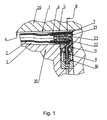
- FIG. 1 is enlarged in section the principal Structure of the sealing device shown.
- the sealing device should the gap. 1 between the adjacent machine parts 20 and 30 seal.
- Main component of the sealing device is the hose 2, which in the groove. 3 is inserted in the machine part 30.
- the tube 2 is not inflated State shown. Filled with compressed air is the hose 2 with his Outer wall on the walls of the groove 3 of the machine part 30 and at the Surface 4 of the machine part 20 at.
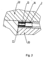
- Fig. 2 is a blind closure of a Hose end shown, while in Fig. 1, a hose end with a Compressed air supply is shown.
- the hose ends are inverted inside and in the indentations 6 and 16, respectively, a support body 5 and 15, respectively inserted. After the inflation of the tube 2, this puts his fully on his Boundary surfaces and it will be a complete seal on the reached the whole length.
- the hose ends lie with their beads 7 and 17 firmly on the machine part 30.
- the indentation 6 designed so that they are in a bead 7 ends, which in the adjacent to the machine part 20 Region 21 axially overlaps the support body 5. It is possible, as in FIG. 1 shown that the second portion 22 of the bead 7, the end face 8 of the Projecting body 5 surmounted.
- the different design of the bead 7 allows the introduction of the tube 9, which is connected to the support body 5.
- the support body 5 has in its interior a bore through which compressed air in the interior of the tube 2 can get.
- the support body 5 is here as Formed hose nozzle having the filling port 23.
- the tube 9 is in the Adapter 10 inserted, which is connected to a compressed air source.
- On the adapter 10 is a spacer 11, which the hose 2 before sharp edges and too much inflation protects.
- the support body 5 with the compressed air supply is slightly larger than that Support body 15.
- the choice of material for the support body or for the pipe or the Adapter 10 is dependent on the existing conditions on site. It is ensure that the hose 2 is inflated quickly and reliably and be emptied again after performing the foaming process of compressed air can.
Landscapes
- Engineering & Computer Science (AREA)
- Mechanical Engineering (AREA)
- General Engineering & Computer Science (AREA)
- Physics & Mathematics (AREA)
- Architecture (AREA)
- Fluid Mechanics (AREA)
- Sealing Devices (AREA)
- Pipe Accessories (AREA)
- Electric Vacuum Cleaner (AREA)
- Seal Device For Vehicle (AREA)
- Glass Compositions (AREA)
- Encapsulation Of And Coatings For Semiconductor Or Solid State Devices (AREA)
- Gasket Seals (AREA)
- Shaping Of Tube Ends By Bending Or Straightening (AREA)
Abstract
Description
Die Erfindung befasst sich mit einer Dichteinrichtung für den Spalt zwischen zwei benachbarten Maschinenteilen, umfassend zumindest einen über einen zusätzlichen Stützkörper aufblasbaren, elastisch dehnbaren Schlauch, der in eine Nut in der Seitenwand eines der Maschinenteile einfügbar ist und der aufgeblasen an eine den Spalt auf der der Nut gegenüberliegenden Seite begrenzende Fläche des anderen Maschinenteils anlegbar ist.The invention is concerned with a sealing device for the gap between two adjacent machine parts, comprising at least one over a additional supporting body inflatable, elastically stretchable hose, which in a groove in the side wall of one of the machine parts can be inserted and the inflated to a gap on the opposite side of the groove limiting surface of the other machine part can be applied.
Dichteinrichtungen dieser Art werden beispielsweise bei Schäumwerkzeugen verwendet, bei denen die beiden Werkzeughälften von großer Ausdehnung sind. Es ist dementsprechend schwierig, den Dichtspalt zwischen den beiden aus Hartwerkstoffen bestehenden Formhälften nach dem Schließen der Form so dicht zu verschließen, dass das in flüssigem Zustand eingebrachte Reaktionsgemisch nicht mehr austreten und die Umgebung verunreinigen kann.Sealing devices of this type are used, for example, in foaming tools used in which the two tool halves of large expansion are. It is therefore difficult to seal the gap between the two made of hard materials mold halves after closing the mold close so tightly that the introduced in the liquid state Reaction mixture no longer escape and contaminate the environment can.
Eine Dichtung der im Oberbegriff des Patentbegehrens beschriebenen Art ist aus der DE PS 196 15 055 bekannt und zum sicheren Verschließen des Spaltes zwischen einer Öffnung eines Hauses und einem in die Öffnung einsetzbaren Rahmen aus einem Hartwerkstoff, bestehend aus einem in den Spalt einsetzbaren und aufblähbaren Schlauch, dessen Enden unmittelbar nebeneinander liegend, radial nach innen gezogen und dort auf Schlauchtüllen aufgefädelt sind, über die Druckluft einspeisbar ist. Im Bereich der Schlauchtüllen ist der Schlauch nicht aufblähbar. Außerdem ergibt sich ein Dichtproblem im Dichtspalt radial außerhalb der Schlauchtüllen, weil die Schlauchenden dort von zwei Seiten mit Radien aufeinander stoßen.A seal which is described in the preamble of the patent application type known from DE PS 196 15 055 and for securely closing the Gap between an opening of a house and one in the opening usable frame of a hard material, consisting of a in the Slit deployable and inflatable tube, the ends immediately lying next to each other, pulled radially inwards and there on hose nozzles are threaded over the compressed air can be fed. Around Hose nozzles, the hose is not inflatable. In addition, there is a Sealing problem in the sealing gap radially outside the hose nozzles, because the Hose ends there from two sides with radii collide.
Aus der US-A-3 897 088 ist eine Dichtung für das stirnseitige Ende eines Kabels oder einer Leitung bekannt, bei der das stirnseitige Ende auf das geschlossene Ende eines Schlauches aufgesetzt und zusammen mit diesem nach Art eines Kolbens zur Druckerhöhung und radialen Aufweitung des Schlauches in den Innenraum des Schlauches hineingeschoben wird, um das stirnseitige Ende des Kabels oder der Leitung gegenüber der Umgebung abzudichten. Eine radiale Abdichtung des Endes gegenüber dritten Gegenständen wird in der Druckschrift nicht erwähnt.From US-A-3 897 088 a seal for the front end of a Cable or a line known in which the front end on the closed end of a hose put on and along with this in the manner of a piston for pressure increase and radial expansion of the Hose is pushed into the interior of the hose to the Front end of the cable or the cable opposite the environment seal. A radial seal of the end opposite third Objects are not mentioned in the document.
Aus der DE 199 16 789 C1 sind Dichtschläuche bekannt, die an ihren beiden Enden außenseitig von Formstücken aus einem Hartwerkstoff umschlossen sind, die in ihrem Bereich zugleich eine Dichtfunktion bezüglich des Dichtspaltes haben. Mindestens eines der Füllstücke ist mit einer leitungsförmigen Ausnehmung versehen, durch die Druckluft in den Schlauch eingeblasen werden kann bzw. daraus entlassen werden kann. Dadurch gelingt es, den aufgeblähten Schlauch auf seiner ganzen Länge mit der gegenüberliegenden Fläche des Formwerkzeugs in Eingriff zu bringen und den Dichtspalt auf dieser Länge abzudichten. Auf den unmittelbaren Bereich der Formstücke hat dies keinen Einfluss. Dort kann daher Leckage entstehen. Die bekannte Dichteinrichtung ist daher für Anwendungszwecke nicht geeignet, in denen der Dichtspalt auf der ganzen Länge abgedichtet werden muss. Beispielsweise für die Herstellung von komplexen Schaumkörpern, bei denen auch in den Endbereichen der Dichtschläuche eine sehr genaue Abdichtung erreicht werden soll, wird eine neue Lösung gesucht.From DE 199 16 789 C1 sealing hoses are known which at their two Ends on the outside surrounded by fittings made of a hard material are in their area at the same time a sealing function with respect to the Have sealing gap. At least one of the patches is with a line-shaped recess provided by the compressed air in the hose can be injected or can be discharged from it. This succeeds it, the bloated hose on its entire length with the to engage the opposite face of the mold and the Sealing gap to seal this length. On the immediate area of Fittings have no influence. There may therefore be leakage. The known sealing device is therefore not suitable for applications in which the sealing gap must be sealed over the entire length. For example, for the production of complex foam bodies in which also in the end of the sealing hoses a very accurate seal is to be achieved, a new solution is sought.
Ein weiterer Nachteil der bekannten Lösung besteht darin, dass die Formstücke teilweise über die Oberflächen der Maschinenteile vorstehen müssen, um eine möglichst gute Abdichtung zu erzielen. Sie bilden daher oftmals ein Hindernis für sekundäre Körper, die bei geöffnetem Formwerkzeug parallel zur Oberfläche des Maschinenteils eingefahren werden. Dies ist beispielsweise oft bei Einlegeteilen der Fall, die zur Verstärkung eines herzustellenden Schaumstoffformteils dienen können. Die vorstehenden Formstücke beeinträchtigen somit in diesen Fällen die Zugänglichkeit des Formwerkzeugs.Another disadvantage of the known solution is that the fittings partially project beyond the surfaces of the machine parts to a To achieve the best possible seal. They are therefore often an obstacle for secondary bodies that are parallel with the mold when the mold is open Retracted surface of the machine part. This is often, for example in the case of inserts, which are used to reinforce a Foam molding can serve. The protruding fittings thus affect in these cases the accessibility of the mold.
Der Erfindung liegt die Aufgabe zugrunde, eine Dichteinrichtung zu schaffen, die eine sichere Abdichtung auch an den Schlauchenden sicherstellt. Die Dichteinrichtung soll möglichst einfach in ihrem Aufbau sein, keinen besonderen Fertigungsaufwand erfordern und vielseitig einsetzbar sein.The invention has for its object to provide a sealing device, which ensures a secure seal even at the hose ends. The Sealing should be as simple as possible in their construction, no require special production costs and be versatile.
Die Lösung der gestellten Aufgabe erfolgt bei einer Dichteinrichtung der eingangs genannten Art erfindungsgemäß dadurch, dass wenigstens ein Ende des Schlauches mit einer umlaufenden und in seinen Innenraum eingreifenden Einstülpung versehen ist, in die der Stützkörper innenseitig eingefügt ist und dass der Schlauch auch im Bereich der Einstülpung aufblähbar und nach dem Aufblasen auf der ganzen Länge der Nut an das andere Maschinenteil anlegbar ist. The solution of the task is carried out at a sealing device of The aforementioned type according to the invention in that at least one end of the hose is provided with a circumferential and engaging in its interior indentation, in which the support body is inserted on the inside and that the hose is also in the Area of invagination inflatable and after inflation on the whole Length of the groove can be applied to the other machine part.
Diese neue Dichteinrichtung ermöglicht eine Ausbildung des Dichtschlauches, bei der die Dichtschlauchenden nicht mehr umgewinkelt werden müssen, sondern das Dichtschlauchende kann gerade auslaufend in der Dichtnut bis zu deren Ende verlegt werden. Durch die Einstülpung bzw. das Umklappen des Schlauches an seinem Ende nach innen wird erreicht, dass dieser bis an sein äußerstes Ende aufblasbar ist. Das nach innen eingestülpte Ende wird bei einer Druckbeaufschlagung mit Druckluft an den Stützkörper angepresst. Der außen liegende Teil des Schlauches wird auf seiner ganzen Länge nach außen aufgebläht und legt sich dabei dichtend an die Gegenfläche an. Endstücke, wie sie zum Stand der Technik gehören, werden nicht benötigt.This new sealing device allows a formation of the sealing tube, in which the sealing tube ends no longer have to be angled, but the sealing tube end can straight up in the sealing groove up to whose end will be postponed. By the invagination or the folding of the Hose at its end inside it is achieved that this is up to extreme end is inflatable. The inwardly inverted end is at a Pressurized compressed air to the support body. The outside lying part of the hose is outward along its entire length bloated and puts it sealingly against the opposite surface. Tails, like they are state of the art, are not needed.
Bevorzugt wird die Einstülpung so ausgeführt, dass sie in einem Wulst endet, welcher die im Einbauzustand der Dichteinrichtung dem Ende des Schlauches zugewandte Stirnfläche des Stützkörpers in zumindest einem an den Spalt angrenzenden, ersten Teilbereich axial übergreift. In besonders günstiger Weise wird der Wulst so gelegt, dass er im Einbauzustand der Dichteinrichtung die Stirnfläche in dem ersten Teilbereich axial weiter übergreift als in einem den Spalt nicht begrenzenden zweiten Teilbereich. Der erste Teilbereich ist dabei an der abzudichtenden Fläche des anderen Maschinenteils anlegbar während der zweite Teilbereich dem Nutgrund der Nut des ersten Maschinenteil zugewandt ist, welche den Schlauch aufnimmt. Die Absetzung des zweiten Teilbereichs des Wulstes kann soweit geführt werden, dass sie im Einbauzustand der Dichteinrichtung hinter die Stirnfläche des Stützkörpers zurückspringt. Diese Ausbildung der Einstülpung ermöglicht den Einsatz einer Schlauchtülle als Stützkörper, die mit einem deren Stirnfläche überragenden Füllanschluss versehen ist. Dieser Füllanschluss ist mit einem Rohr verbunden, der einem Adapter zugeführt wird. Dieser Adapter kann um 90 ° versetzt zum Schlauchende im ersten Maschinenteil untergebracht sein.Preferably, the indentation is carried out so that it ends in a bead, which faces the end of the hose in the installed state of the sealing device end face of the Supporting body in at least one adjacent to the gap, first Partial area overlaps axially. In a particularly favorable manner, the bead is so placed in such a way that in the installed state of the sealing device it continues to axially overlap the end face in the first subregion as in a second portion not limiting the gap. The first Part of this area is at the sealed area of the other Machine part can be applied while the second portion of the groove bottom of the groove facing the first machine part which receives the hose. The Deposition of the second portion of the bead can be performed so far, that it springs back in the installed state of the sealing device behind the end face of the support body. These Forming the invagination allows the use of a hose nozzle as Supporting body, the one with its end face superior Füllanschluss is provided. This filling connection is connected to a pipe, which is a Adapter is supplied. This adapter can be offset by 90 ° to the Hose end be housed in the first machine part.
Um nach der Einbringung der Stützkörpers in die Einstülpung eine sichere Aufblähbarkeit des Schlauches auch im Bereich der Einstülpung sicherzustellen, hat es sich als vorteilhaft bewährt, wenn der Schlauch zumindest dort innenseitig mit in Umfangsrichtung verteilten Rippen oder Nuten versehen ist. Nach der Einstülpung bilden die Lücken zwischen den Rippen und der Schlauchwandung bzw. in den Nuten Strömungskanäle, durch die unter Druck stehendes Strömungsmittel, beispielsweise Druckluft, in den Spalt eindringen und den Schlauch im Bereich der Einstülpung aufblähen kann.To after the introduction of the support body in the invagination a safe Inflatability of the tube also in the area of the invagination To ensure it has proven to be advantageous when the hose at least there on the inside with circumferentially distributed ribs or grooves is provided. After the invagination form the gaps between the ribs and the hose wall or in the grooves flow channels, through the under Pressurized fluid, such as compressed air, into the gap penetrate and inflate the hose in the area of the invagination.
Es ist günstig, wenn der erste Schlauch sowohl in radialer als auch in axialer Richtung dehnbar ist, damit er beim Aufblähen sich voll an die ihn umgebenden Maschinenteile anpassen kann.It is advantageous if the first tube in both radial and axial Direction is stretchable so that it is fully inflated to the surrounding him Machine parts can adapt.
Anhand eines in der Zeichnung dargestellten Ausführungsbeispiels wird die Erfindung nachstehend näher erläutert.Reference to an embodiment shown in the drawing, the Invention explained in more detail below.
In den beiliegenden Figuren 1 und 2 ist vergrößert im Schnitt der prinzipielle
Aufbau der Dichteinrichtung gezeigt. Die Dichteinrichtung soll den Spalt 1
zwischen den benachbarten Maschinenteilen 20 und 30 abdichten.
Hauptbestandteil der Dichteinrichtung ist der Schlauch 2, welcher in die Nut 3
im Maschinenteil 30 eingefügt ist. Der Schlauch 2 ist im nicht aufgeblähten
Zustand gezeigt. Mit Druckluft gefüllt liegt der Schlauch 2 mit seiner
Außenwand an den Wänden der Nut 3 des Maschinenteils 30 und an der
Fläche 4 des Maschinenteils 20 an. In der Fig. 2 ist ein Blindabschluss eines
Schlauchendes gezeigt, während in der Fig. 1 ein Schlauchende mit einer
Druckluftzufuhr dargestellt ist. Die Schlauchenden sind nach innen eingestülpt
und in die Einstülpungen 6 bzw. 16 ist jeweils ein Stützkörper 5 bzw. 15
eingefügt. Nach dem Aufblähen des Schlauches 2 legt sich dieser voll an seine
Begrenzungsflächen an und es wird eine vollständige Abdichtung auf der
ganzen Länge erreicht. Die Schlauchenden liegen mit ihren Wülsten 7 und 17
fest am Maschinenteil 30 an.In the accompanying figures 1 and 2 is enlarged in section the principal
Structure of the sealing device shown. The sealing device should the gap. 1
between the
Um die Luftzufuhr über den Stützkörper 5 in den Schlauch 2 zu ermöglichen,
ist, wie auf der Figur 1 sichtbar, die Einstülpung 6 so ausgestaltet, dass sie in
einem Wulst 7 endet, welcher in dem an das Maschinenteil 20 angrenzenden
Bereich 21 den Stützkörper 5 axial übergreift. Es ist möglich, wie in der Figur 1
gezeigt, dass auch der zweite Teilbereich 22 der Wulst 7 die Stirnfläche 8 des
Stützkörpers 5 überragt. Die unterschiedliche Ausbildung der Wulst 7 gestattet
die Einführung des Rohres 9, das mit dem Stützkörper 5 verbunden ist. Der
Stützkörper 5 hat in seinem Inneren eine Bohrung, durch welche Druckluft in
das Innere des Schlauches 2 gelangen kann. Der Stützkörper 5 ist hier als
Schlauchtülle ausgebildet, die den Füllanschluss 23 hat. Das Rohr 9 ist in den
Adapter 10 eingefügt, welcher an eine Druckluftquelle angeschlossen ist. Auf
dem Adapter 10 befindet sich ein Distanzstück 11, welches den Schlauch 2 vor
scharfen Kanten und zu weitem Aufblasen schützt.In order to allow the air supply via the support body 5 in the tube 2,
is, as visible in Figure 1, the indentation 6 designed so that they are in
a bead 7 ends, which in the adjacent to the
Der Stützkörper 5 mit der Druckluftzufuhr ist geringfügig größer als der Stützkörper 15. Für die Unterbringung dieses vergrößerten Stützkörpers 5 ist die Nut 3, wie auf der Zeichnung ersichtlich, an ihrem auslaufenden Ende geringfügig erweitert.The support body 5 with the compressed air supply is slightly larger than that Support body 15. For the accommodation of this enlarged support body 5 is the groove 3, as seen in the drawing, at its expiring end slightly extended.
Die Auswahl des Materials für die Stützkörper oder auch für das Rohr bzw. den
Adapter 10 ist abhängig von den vor Ort vorhandenen Gegebenheiten. Es ist
sicherzustellen, dass der Schlauch 2 schnell und zuverlässig aufgeblasen und
nach Durchführung des Schäumvorgangs von Druckluft wieder entleert werden
kann.The choice of material for the support body or for the pipe or the
Claims (9)
- A sealing arrangement for the gap (1) between two adjacent machine parts (20, 30), comprising at least one elastically stretchable tube (2), which can be inflated via an additional supporting body (5), can be inserted into a groove (3) in the side wall of one of the machine parts (30) and, when inflated, can be applied against a surface of the other machine part (20), which surface delimits the gap (1) on the side opposite the groove (3), characterized in that at least one end of the tube (2) is provided with a turned-in portion (6, 16) which runs around it and extends into its interior and into which the supporting body (5) is inserted on the inside, and in that the tube (2) can be inflated in the region of the turned-in portion (6, 16) as well and, after inflation, can be applied against the other machine part (20) over the entire length of the groove (3).
- A sealing arrangement according to claim 1, characterized in that the turned-in portion (6, 16) ends in a bead (7, 17), which, in the fitted state of the sealing arrangement, overlaps axially that end face (8) of the supporting body (5) facing this end in at least a first part region (21) adjacent to the gap (1).
- A sealing arrangement according to either of claims 1 and 2, characterized in that, in the fitted state of the sealing arrangement, the bead (7) axially overlaps the end face (8) in the first part region (21) further than in a second part region (22) which does not delimit the gap (1).
- A sealing arrangement according to any one of claims 1 to 3, characterized in that, in the fitted state of the sealing arrangement, the bead (7) is in the second part region (22) designed to be set back behind that end face (8) of the supporting body (5) facing the end of the tube (2).
- A sealing arrangement according to any one of claims 1 to 4, characterized in that the supporting body (5) is designed as a hose nozzle.
- A sealing arrangement according to any one of claims 1 to 5, characterized in that the hose nozzle is provided with a filling connection (23) projecting beyond its end face (8).
- A sealing arrangement according to claim 6, characterized in that the filling connection comprises a pipe (9).
- A sealing arrangement according to any one of claims 1 to 6, characterized in that the tube (2) is provided on the inside with ribs or grooves distributed in the circumferential direction.
- A sealing arrangement according to any one of claims 1 to 8, characterized in that the tube (2) is stretchable in the radial and the axial direction.
Applications Claiming Priority (2)
| Application Number | Priority Date | Filing Date | Title |
|---|---|---|---|
| DE10220842 | 2002-05-08 | ||
| DE2002120842 DE10220842B4 (en) | 2002-05-08 | 2002-05-08 | sealing device |
Publications (3)
| Publication Number | Publication Date |
|---|---|
| EP1361380A2 EP1361380A2 (en) | 2003-11-12 |
| EP1361380A3 EP1361380A3 (en) | 2004-07-14 |
| EP1361380B1 true EP1361380B1 (en) | 2005-09-28 |
Family
ID=29225139
Family Applications (1)
| Application Number | Title | Priority Date | Filing Date |
|---|---|---|---|
| EP20030004049 Expired - Lifetime EP1361380B1 (en) | 2002-05-08 | 2003-02-25 | Sealing arrangement |
Country Status (6)
| Country | Link |
|---|---|
| US (1) | US6953195B2 (en) |
| EP (1) | EP1361380B1 (en) |
| CN (1) | CN1300492C (en) |
| AT (1) | ATE305578T1 (en) |
| DE (2) | DE10220842B4 (en) |
| ES (1) | ES2251635T3 (en) |
Families Citing this family (11)
| Publication number | Priority date | Publication date | Assignee | Title |
|---|---|---|---|---|
| US7376879B2 (en) | 2001-10-19 | 2008-05-20 | Interdigital Technology Corporation | MAC architecture in wireless communication systems supporting H-ARQ |
| US8018945B2 (en) | 2004-04-29 | 2011-09-13 | Interdigital Technology Corporation | Method and apparatus for forwarding non-consecutive data blocks in enhanced uplink transmissions |
| DE102004038114B4 (en) * | 2004-08-03 | 2008-08-28 | Frimo Group Gmbh | Sealing device for the gap between two adjacent, unyielding machine parts |
| AT8084U1 (en) | 2005-01-19 | 2006-01-15 | Alba Tooling & Engineering Gmb | SEALING DEVICE |
| DE102006015184A1 (en) * | 2006-04-01 | 2007-10-11 | Krauss-Maffei Kunststofftechnik Gmbh | Inflatable sealing device for a mold |
| DE102007013450B3 (en) * | 2007-03-21 | 2008-09-04 | Frimo Group Gmbh | Sealing arrangement for the gap between neighboring machine parts comprises a tube elastically expanding over a support body which has an outer profile fitting the contour of a groove |
| EP2636905B1 (en) * | 2012-03-05 | 2015-07-08 | Sulzer Management AG | Sealing assembly and pump with a sealing assembly |
| DE102013006833B4 (en) * | 2013-04-22 | 2014-10-30 | Weiss Gwe Gmbh | Device and method for sealing a boundary opening and workplace arrangement with the device and adapter for it |
| DE102013214547A1 (en) * | 2013-07-25 | 2015-01-29 | Bayerische Motoren Werke Aktiengesellschaft | Flexible sealing element with variable stiffening |
| DE102015111078B4 (en) * | 2015-07-09 | 2017-09-14 | Kraussmaffei Technologies Gmbh | Foaming tool with mobile sealing end piece |
| AT518180B1 (en) * | 2016-01-28 | 2017-08-15 | Alba Tooling & Eng Gmbh | sealing device |
Citations (1)
| Publication number | Priority date | Publication date | Assignee | Title |
|---|---|---|---|---|
| DE19615055A1 (en) * | 1996-04-17 | 1997-10-23 | Bruno Winiger | Method for sealing house openings, especially doors and windows of basement area |
Family Cites Families (12)
| Publication number | Priority date | Publication date | Assignee | Title |
|---|---|---|---|---|
| US3749093A (en) * | 1971-08-10 | 1973-07-31 | S Bloom | Insertable device package |
| US3897088A (en) * | 1973-12-12 | 1975-07-29 | Amp Inc | Sealing boot |
| US3985365A (en) * | 1975-11-06 | 1976-10-12 | Bartholomew Thomas Catanzaro | Remotely actuated emergency shaft seal |
| NL7609734A (en) * | 1976-09-01 | 1978-03-03 | Ihc Holland Nv | SEAL FOR THE LOOSENING OF A HOPPER OR SIMILAR BOTTOM LOOSER. |
| DE3631875A1 (en) * | 1986-09-19 | 1988-04-07 | Continental Gummi Werke Ag | Endless connection for tubes of pneumatic tyres |
| US4923223A (en) * | 1988-08-05 | 1990-05-08 | Plastic Specialties And Technologies Investments, Inc. | Kink impeding hose for spraying water |
| US5476268A (en) * | 1990-03-15 | 1995-12-19 | Unicraft Oy | Seal assembly with a hard seal layer actuated through a silicone layer |
| DE19645904A1 (en) * | 1996-11-07 | 1998-05-20 | Hausach Umformtechnik | Inflatable sealing ring |
| DE19715293B4 (en) * | 1997-02-11 | 2005-06-02 | Johannes Schäfer vorm. Stettiner Schraubenwerke GmbH & Co. KG | Plug connection for pipelines |
| DE19708579C2 (en) * | 1997-03-03 | 1999-06-17 | Fritsche Moellmann Gmbh Co Kg | Sealing device |
| DE19916789C1 (en) | 1999-04-15 | 2000-09-21 | Fritsche, Moellmann Gmbh & Co Kg | Seal between the surfaces of two machine units is an inflatable hose within an open groove flush at one surface which can be filled with a pressure medium to bear in a sealed fit against the other surface |
| DE20214798U1 (en) * | 2002-09-25 | 2003-01-16 | Heidel GmbH & Co KG, 49504 Lotte | Elastic inflatable sealing cord for forming tools, in particular, for production of vehicle interior components comprises an end section which is closed by an end piece fixed by vulcanization |
-
2002
- 2002-05-08 DE DE2002120842 patent/DE10220842B4/en not_active Expired - Fee Related
-
2003
- 2003-02-25 AT AT03004049T patent/ATE305578T1/en active
- 2003-02-25 EP EP20030004049 patent/EP1361380B1/en not_active Expired - Lifetime
- 2003-02-25 ES ES03004049T patent/ES2251635T3/en not_active Expired - Lifetime
- 2003-02-25 DE DE50301241T patent/DE50301241D1/en not_active Expired - Lifetime
- 2003-04-28 CN CNB031224563A patent/CN1300492C/en not_active Expired - Fee Related
- 2003-05-07 US US10/431,187 patent/US6953195B2/en not_active Expired - Lifetime
Patent Citations (1)
| Publication number | Priority date | Publication date | Assignee | Title |
|---|---|---|---|---|
| DE19615055A1 (en) * | 1996-04-17 | 1997-10-23 | Bruno Winiger | Method for sealing house openings, especially doors and windows of basement area |
Also Published As
| Publication number | Publication date |
|---|---|
| EP1361380A2 (en) | 2003-11-12 |
| DE10220842B4 (en) | 2005-06-16 |
| ATE305578T1 (en) | 2005-10-15 |
| DE50301241D1 (en) | 2005-11-03 |
| DE10220842A1 (en) | 2004-05-13 |
| EP1361380A3 (en) | 2004-07-14 |
| CN1456829A (en) | 2003-11-19 |
| ES2251635T3 (en) | 2006-05-01 |
| US20040000764A1 (en) | 2004-01-01 |
| CN1300492C (en) | 2007-02-14 |
| US6953195B2 (en) | 2005-10-11 |
Similar Documents
| Publication | Publication Date | Title |
|---|---|---|
| DE69733800T2 (en) | Device and cartridge for an evertable tubular bag | |
| DE69701633T2 (en) | SEALING A GAP BETWEEN A PIPE AND THE PIPE LINING THEREFORE | |
| EP1361380B1 (en) | Sealing arrangement | |
| DE1475683A1 (en) | Clutch sealing ring | |
| EP2924322B1 (en) | Sealing device | |
| EP0533999B1 (en) | Method for sealing pipelines | |
| EP3011220B1 (en) | System and method for advancing a pipe assembly | |
| EP3376087B1 (en) | Threaded branch for sewer pipe with irregularities | |
| EP1640646B1 (en) | Sealing arrangement | |
| EP3491254B1 (en) | Piston unit of a hydraulic cylinder | |
| EP3139079B1 (en) | Construction kit for retrofitting a pipe conduit connection of a thick-walled pipe | |
| DE2452221A1 (en) | Hydrodynamic working cylinder - incorporates sealing sleeve for working piston with gap between sleeve and cylinder | |
| DE4114902A1 (en) | SHUT-OFF DEVICE | |
| DE9412355U1 (en) | Shut-off device for pipelines for the transport of liquid or gaseous media | |
| DE102015204799A1 (en) | sealing device | |
| EP3741469A1 (en) | Multichamber cartridge and method for the filling of same | |
| DE3542048C2 (en) | ||
| DE4101531A1 (en) | DEVICE FOR DETECTING AND SEALING LEAKS IN PIPES | |
| DE29806603U1 (en) | Sealing element for sealing pipes | |
| DE2059905C2 (en) | Method and device for blocking the flow path in a pipeline under pressure | |
| DE69615152T2 (en) | Automatic molding tool, on plastic pipes, of large length sleeves | |
| DE102016104693B4 (en) | Foaming tool with inflatable end / connecting / closing piece and method for sealing a foaming tool | |
| DE9202199U1 (en) | Packer with inflatable sealing elements for support on a pipe wall | |
| EP4151554A1 (en) | Coaxial cartridge with expansion joints for storing and reset force-free extrusion of a flowable multi-component mass | |
| DE1901669A1 (en) | Rotary valve seat and process for its manufacture |
Legal Events
| Date | Code | Title | Description |
|---|---|---|---|
| PUAI | Public reference made under article 153(3) epc to a published international application that has entered the european phase |
Free format text: ORIGINAL CODE: 0009012 |
|
| AK | Designated contracting states |
Kind code of ref document: A2 Designated state(s): AT BE BG CH CY CZ DE DK EE ES FI FR GB GR HU IE IT LI LU MC NL PT SE SI SK TR |
|
| AX | Request for extension of the european patent |
Extension state: AL LT LV MK RO |
|
| PUAL | Search report despatched |
Free format text: ORIGINAL CODE: 0009013 |
|
| AK | Designated contracting states |
Kind code of ref document: A3 Designated state(s): AT BE BG CH CY CZ DE DK EE ES FI FR GB GR HU IE IT LI LU MC NL PT SE SI SK TR |
|
| AX | Request for extension of the european patent |
Extension state: AL LT LV MK RO |
|
| 17P | Request for examination filed |
Effective date: 20040616 |
|
| 17Q | First examination report despatched |
Effective date: 20040917 |
|
| AKX | Designation fees paid |
Designated state(s): AT BE BG CH CY CZ DE DK EE ES FI FR GB GR HU IE IT LI LU MC NL PT SE SI SK TR |
|
| GRAP | Despatch of communication of intention to grant a patent |
Free format text: ORIGINAL CODE: EPIDOSNIGR1 |
|
| GRAS | Grant fee paid |
Free format text: ORIGINAL CODE: EPIDOSNIGR3 |
|
| GRAA | (expected) grant |
Free format text: ORIGINAL CODE: 0009210 |
|
| AK | Designated contracting states |
Kind code of ref document: B1 Designated state(s): AT BE BG CH CY CZ DE DK EE ES FI FR GB GR HU IE IT LI LU MC NL PT SE SI SK TR |
|
| PG25 | Lapsed in a contracting state [announced via postgrant information from national office to epo] |
Ref country code: IT Free format text: LAPSE BECAUSE OF FAILURE TO SUBMIT A TRANSLATION OF THE DESCRIPTION OR TO PAY THE FEE WITHIN THE PRESCRIBED TIME-LIMIT;WARNING: LAPSES OF ITALIAN PATENTS WITH EFFECTIVE DATE BEFORE 2007 MAY HAVE OCCURRED AT ANY TIME BEFORE 2007. THE CORRECT EFFECTIVE DATE MAY BE DIFFERENT FROM THE ONE RECORDED. Effective date: 20050928 Ref country code: NL Free format text: LAPSE BECAUSE OF FAILURE TO SUBMIT A TRANSLATION OF THE DESCRIPTION OR TO PAY THE FEE WITHIN THE PRESCRIBED TIME-LIMIT Effective date: 20050928 Ref country code: CZ Free format text: LAPSE BECAUSE OF FAILURE TO SUBMIT A TRANSLATION OF THE DESCRIPTION OR TO PAY THE FEE WITHIN THE PRESCRIBED TIME-LIMIT Effective date: 20050928 Ref country code: IE Free format text: LAPSE BECAUSE OF FAILURE TO SUBMIT A TRANSLATION OF THE DESCRIPTION OR TO PAY THE FEE WITHIN THE PRESCRIBED TIME-LIMIT Effective date: 20050928 Ref country code: SI Free format text: LAPSE BECAUSE OF FAILURE TO SUBMIT A TRANSLATION OF THE DESCRIPTION OR TO PAY THE FEE WITHIN THE PRESCRIBED TIME-LIMIT Effective date: 20050928 Ref country code: SK Free format text: LAPSE BECAUSE OF FAILURE TO SUBMIT A TRANSLATION OF THE DESCRIPTION OR TO PAY THE FEE WITHIN THE PRESCRIBED TIME-LIMIT Effective date: 20050928 Ref country code: FI Free format text: LAPSE BECAUSE OF FAILURE TO SUBMIT A TRANSLATION OF THE DESCRIPTION OR TO PAY THE FEE WITHIN THE PRESCRIBED TIME-LIMIT Effective date: 20050928 |
|
| REG | Reference to a national code |
Ref country code: GB Ref legal event code: FG4D Free format text: NOT ENGLISH |
|
| REG | Reference to a national code |
Ref country code: CH Ref legal event code: EP |
|
| REG | Reference to a national code |
Ref country code: IE Ref legal event code: FG4D Free format text: LANGUAGE OF EP DOCUMENT: GERMAN |
|
| REF | Corresponds to: |
Ref document number: 50301241 Country of ref document: DE Date of ref document: 20051103 Kind code of ref document: P |
|
| GBT | Gb: translation of ep patent filed (gb section 77(6)(a)/1977) |
Effective date: 20051111 |
|
| RAP2 | Party data changed (patent owner data changed or rights of a patent transferred) |
Owner name: FRIMO GROUP GMBH |
|
| PG25 | Lapsed in a contracting state [announced via postgrant information from national office to epo] |
Ref country code: DK Free format text: LAPSE BECAUSE OF FAILURE TO SUBMIT A TRANSLATION OF THE DESCRIPTION OR TO PAY THE FEE WITHIN THE PRESCRIBED TIME-LIMIT Effective date: 20051228 Ref country code: SE Free format text: LAPSE BECAUSE OF FAILURE TO SUBMIT A TRANSLATION OF THE DESCRIPTION OR TO PAY THE FEE WITHIN THE PRESCRIBED TIME-LIMIT Effective date: 20051228 Ref country code: GR Free format text: LAPSE BECAUSE OF FAILURE TO SUBMIT A TRANSLATION OF THE DESCRIPTION OR TO PAY THE FEE WITHIN THE PRESCRIBED TIME-LIMIT Effective date: 20051228 Ref country code: BG Free format text: LAPSE BECAUSE OF FAILURE TO SUBMIT A TRANSLATION OF THE DESCRIPTION OR TO PAY THE FEE WITHIN THE PRESCRIBED TIME-LIMIT Effective date: 20051228 |
|
| NLT2 | Nl: modifications (of names), taken from the european patent patent bulletin |
Owner name: FRIMO GROUP GMBH Effective date: 20051207 |
|
| PG25 | Lapsed in a contracting state [announced via postgrant information from national office to epo] |
Ref country code: MC Free format text: LAPSE BECAUSE OF NON-PAYMENT OF DUE FEES Effective date: 20060228 Ref country code: PT Free format text: LAPSE BECAUSE OF FAILURE TO SUBMIT A TRANSLATION OF THE DESCRIPTION OR TO PAY THE FEE WITHIN THE PRESCRIBED TIME-LIMIT Effective date: 20060228 Ref country code: BE Free format text: LAPSE BECAUSE OF NON-PAYMENT OF DUE FEES Effective date: 20060228 Ref country code: LU Free format text: LAPSE BECAUSE OF NON-PAYMENT OF DUE FEES Effective date: 20060228 |
|
| NLV1 | Nl: lapsed or annulled due to failure to fulfill the requirements of art. 29p and 29m of the patents act | ||
| PG25 | Lapsed in a contracting state [announced via postgrant information from national office to epo] |
Ref country code: HU Free format text: LAPSE BECAUSE OF FAILURE TO SUBMIT A TRANSLATION OF THE DESCRIPTION OR TO PAY THE FEE WITHIN THE PRESCRIBED TIME-LIMIT Effective date: 20060329 |
|
| REG | Reference to a national code |
Ref country code: ES Ref legal event code: FG2A Ref document number: 2251635 Country of ref document: ES Kind code of ref document: T3 |
|
| REG | Reference to a national code |
Ref country code: IE Ref legal event code: FD4D |
|
| ET | Fr: translation filed | ||
| PLBE | No opposition filed within time limit |
Free format text: ORIGINAL CODE: 0009261 |
|
| STAA | Information on the status of an ep patent application or granted ep patent |
Free format text: STATUS: NO OPPOSITION FILED WITHIN TIME LIMIT |
|
| 26N | No opposition filed |
Effective date: 20060629 |
|
| PG25 | Lapsed in a contracting state [announced via postgrant information from national office to epo] |
Ref country code: CH Free format text: LAPSE BECAUSE OF NON-PAYMENT OF DUE FEES Effective date: 20070228 Ref country code: LI Free format text: LAPSE BECAUSE OF NON-PAYMENT OF DUE FEES Effective date: 20070228 |
|
| REG | Reference to a national code |
Ref country code: CH Ref legal event code: PL |
|
| BERE | Be: lapsed |
Owner name: FRIMO GROUP G.M.B.H. & CO. Effective date: 20060228 |
|
| PG25 | Lapsed in a contracting state [announced via postgrant information from national office to epo] |
Ref country code: EE Free format text: LAPSE BECAUSE OF FAILURE TO SUBMIT A TRANSLATION OF THE DESCRIPTION OR TO PAY THE FEE WITHIN THE PRESCRIBED TIME-LIMIT Effective date: 20050928 |
|
| PG25 | Lapsed in a contracting state [announced via postgrant information from national office to epo] |
Ref country code: TR Free format text: LAPSE BECAUSE OF FAILURE TO SUBMIT A TRANSLATION OF THE DESCRIPTION OR TO PAY THE FEE WITHIN THE PRESCRIBED TIME-LIMIT Effective date: 20050928 |
|
| PG25 | Lapsed in a contracting state [announced via postgrant information from national office to epo] |
Ref country code: CY Free format text: LAPSE BECAUSE OF FAILURE TO SUBMIT A TRANSLATION OF THE DESCRIPTION OR TO PAY THE FEE WITHIN THE PRESCRIBED TIME-LIMIT Effective date: 20050928 |
|
| REG | Reference to a national code |
Ref country code: FR Ref legal event code: PLFP Year of fee payment: 14 |
|
| REG | Reference to a national code |
Ref country code: FR Ref legal event code: PLFP Year of fee payment: 15 |
|
| REG | Reference to a national code |
Ref country code: FR Ref legal event code: PLFP Year of fee payment: 16 |
|
| PGFP | Annual fee paid to national office [announced via postgrant information from national office to epo] |
Ref country code: GB Payment date: 20220218 Year of fee payment: 20 Ref country code: DE Payment date: 20220215 Year of fee payment: 20 Ref country code: AT Payment date: 20220218 Year of fee payment: 20 |
|
| PGFP | Annual fee paid to national office [announced via postgrant information from national office to epo] |
Ref country code: FR Payment date: 20220222 Year of fee payment: 20 Ref country code: ES Payment date: 20220301 Year of fee payment: 20 |
|
| REG | Reference to a national code |
Ref country code: DE Ref legal event code: R071 Ref document number: 50301241 Country of ref document: DE |
|
| REG | Reference to a national code |
Ref country code: GB Ref legal event code: PE20 Expiry date: 20230224 |
|
| REG | Reference to a national code |
Ref country code: AT Ref legal event code: MK07 Ref document number: 305578 Country of ref document: AT Kind code of ref document: T Effective date: 20230225 |
|
| REG | Reference to a national code |
Ref country code: ES Ref legal event code: FD2A Effective date: 20230426 |
|
| PG25 | Lapsed in a contracting state [announced via postgrant information from national office to epo] |
Ref country code: GB Free format text: LAPSE BECAUSE OF EXPIRATION OF PROTECTION Effective date: 20230224 |
|
| PG25 | Lapsed in a contracting state [announced via postgrant information from national office to epo] |
Ref country code: ES Free format text: LAPSE BECAUSE OF EXPIRATION OF PROTECTION Effective date: 20230226 |