EP3766591B1 - Cleaning apparatus - Google Patents
Cleaning apparatus Download PDFInfo
- Publication number
- EP3766591B1 EP3766591B1 EP20181045.4A EP20181045A EP3766591B1 EP 3766591 B1 EP3766591 B1 EP 3766591B1 EP 20181045 A EP20181045 A EP 20181045A EP 3766591 B1 EP3766591 B1 EP 3766591B1
- Authority
- EP
- European Patent Office
- Prior art keywords
- cleaning
- axis
- saddle
- arm
- column
- Prior art date
- Legal status (The legal status is an assumption and is not a legal conclusion. Google has not performed a legal analysis and makes no representation as to the accuracy of the status listed.)
- Active
Links
Images



Classifications
-
- B—PERFORMING OPERATIONS; TRANSPORTING
- B08—CLEANING
- B08B—CLEANING IN GENERAL; PREVENTION OF FOULING IN GENERAL
- B08B3/00—Cleaning by methods involving the use or presence of liquid or steam
- B08B3/02—Cleaning by the force of jets or sprays
-
- B—PERFORMING OPERATIONS; TRANSPORTING
- B08—CLEANING
- B08B—CLEANING IN GENERAL; PREVENTION OF FOULING IN GENERAL
- B08B3/00—Cleaning by methods involving the use or presence of liquid or steam
- B08B3/02—Cleaning by the force of jets or sprays
- B08B3/022—Cleaning travelling work
-
- B—PERFORMING OPERATIONS; TRANSPORTING
- B08—CLEANING
- B08B—CLEANING IN GENERAL; PREVENTION OF FOULING IN GENERAL
- B08B13/00—Accessories or details of general applicability for machines or apparatus for cleaning
-
- B—PERFORMING OPERATIONS; TRANSPORTING
- B08—CLEANING
- B08B—CLEANING IN GENERAL; PREVENTION OF FOULING IN GENERAL
- B08B5/00—Cleaning by methods involving the use of air flow or gas flow
- B08B5/02—Cleaning by the force of jets, e.g. blowing-out cavities
- B08B5/023—Cleaning travelling work
-
- B—PERFORMING OPERATIONS; TRANSPORTING
- B25—HAND TOOLS; PORTABLE POWER-DRIVEN TOOLS; MANIPULATORS
- B25J—MANIPULATORS; CHAMBERS PROVIDED WITH MANIPULATION DEVICES
- B25J11/00—Manipulators not otherwise provided for
- B25J11/008—Manipulators for service tasks
- B25J11/0085—Cleaning
-
- B—PERFORMING OPERATIONS; TRANSPORTING
- B25—HAND TOOLS; PORTABLE POWER-DRIVEN TOOLS; MANIPULATORS
- B25J—MANIPULATORS; CHAMBERS PROVIDED WITH MANIPULATION DEVICES
- B25J5/00—Manipulators mounted on wheels or on carriages
- B25J5/02—Manipulators mounted on wheels or on carriages travelling along a guideway
-
- B—PERFORMING OPERATIONS; TRANSPORTING
- B25—HAND TOOLS; PORTABLE POWER-DRIVEN TOOLS; MANIPULATORS
- B25J—MANIPULATORS; CHAMBERS PROVIDED WITH MANIPULATION DEVICES
- B25J9/00—Program-controlled manipulators
- B25J9/02—Program-controlled manipulators characterised by movement of the arms, e.g. cartesian coordinate type
- B25J9/04—Program-controlled manipulators characterised by movement of the arms, e.g. cartesian coordinate type by rotating at least one arm, excluding the head movement itself, e.g. cylindrical coordinate type or polar coordinate type
- B25J9/046—Revolute coordinate type
-
- F—MECHANICAL ENGINEERING; LIGHTING; HEATING; WEAPONS; BLASTING
- F26—DRYING
- F26B—DRYING SOLID MATERIALS OR OBJECTS BY REMOVING LIQUID THEREFROM
- F26B21/00—Arrangements for supplying or controlling air or other gases for drying solid materials or objects
- F26B21/001—Air generating units, e.g. movable or independent of drying enclosure
-
- F—MECHANICAL ENGINEERING; LIGHTING; HEATING; WEAPONS; BLASTING
- F26—DRYING
- F26B—DRYING SOLID MATERIALS OR OBJECTS BY REMOVING LIQUID THEREFROM
- F26B21/00—Arrangements for supplying or controlling air or other gases for drying solid materials or objects
- F26B21/50—Ducting arrangements from the source of air or other gases to the materials or objects being dried
-
- B—PERFORMING OPERATIONS; TRANSPORTING
- B25—HAND TOOLS; PORTABLE POWER-DRIVEN TOOLS; MANIPULATORS
- B25J—MANIPULATORS; CHAMBERS PROVIDED WITH MANIPULATION DEVICES
- B25J9/00—Program-controlled manipulators
- B25J9/02—Program-controlled manipulators characterised by movement of the arms, e.g. cartesian coordinate type
- B25J9/04—Program-controlled manipulators characterised by movement of the arms, e.g. cartesian coordinate type by rotating at least one arm, excluding the head movement itself, e.g. cylindrical coordinate type or polar coordinate type
- B25J9/041—Cylindrical coordinate type
- B25J9/042—Cylindrical coordinate type comprising an articulated arm
Definitions
- the present invention relates to a cleaning apparatus.
- a conventional cleaning apparatus includes a cleaning tank in which a plurality of nozzles are arranged at the bottom, a robot hand for gripping a workpiece, and a multi-axis robot facing the cleaning tank ( Japanese Patent No. 4317502 (hereinafter, Patent Literature 1)).
- DE 102016005434 A1 discloses a robot cell with a robot cell room with at least one charging frame, at least one robot on which at least one gripping tool is arranged, at least one cleaning station and at least one cleaning medium, thereby characterized in that the robot grips at least one workpiece to be cleaned with the gripping tool and inserts it directly or indirectly into the charging rack and removes it according to the FiFo principle.
- EP 3636357 A1 discloses a compact versatile cell-type cleaning device and cell-type drying device.
- the cleaning apparatus of Patent Literature 1 includes a robot with a wide range of motion, the installation area of the cleaning apparatus is increased.
- An object of the present invention is to provide a compact cleaning apparatus including a robot with a narrow range of motion.
- Claim 1 of of the present invention provides a cleaning apparatus, including:
- the cleaning liquid is, for example, an aqueous cleaning liquid.
- the foreign substances that adhere to the workpiece are, for example, chips or oil.
- Cleaning includes deburring with a high pressure jet.
- the separation wall is arranged in connection with the opposite side of the surface (second side surface) on which the column of the cleaning chamber is installed, and a sufficient gap is provided between the separation wall and the column.
- a cleaning station one space separated by the separation wall
- a drying station the other space
- the transfer passage is continuous with the cleaning station and the drying station.
- the multi-axis robot drives the first to sixth axes simultaneously and can freely move the three-dimensional space.
- the multi-axis robot is numerically controlled.
- the column has a base plate located on the side of the cleaning chamber.
- the through hole is formed in the base plate.
- the linear guide is located on the side of the base plate opposite to the cleaning chamber.
- An arm portion is arranged on a single axis robot.
- the arm portion is an articulated robot extending in a straight line, and two rotation axes, i.e., a second axis and a third axis, are arranged at the basal end portion thereof.
- the arm portion is divided into a first arm disposed at the basal end and a second arm disposed at the distal end.
- the second arm can be rotated about the fourth axis extending along the first arm.
- Two rotation axes i. e., the fifth axis and the sixth axis, are arranged at the distal end of the second arm.
- Motors of each axis are, for example, servo motors, or stepping motors
- the telescopic covers are, for example, bellows.
- the telescopic cover is arranged on the surface of the base plate on the cleaning chamber side.
- the telescopic cover is disposed above and below the vertical moving saddles, respectively.
- the moving end of the respective telescopic cover is fixed to the vertical moving saddles, and the fixed end is fixed to the column.
- the telescopic cover suppresses the cleaning liquid and foreign matter from entering into the column via the through hole.
- the cleaning chamber includes a loading port and an unloading port.
- the loading port may be located in the cleaning station.
- the loading port may be located on a wall near the cleaning station, among the walls surrounding the transfer passage.
- the side surface of the cleaning chamber has a loading port.
- the unloading port may be located at the drying station.
- the unloading port may be located on a wall near the drying station, among the walls surrounding the transfer passage. In place of the loading port and the unloading port, a single loading/unloading port may be disposed.
- the cleaning apparatus may include an air supply device, which may be a blower or a compressor.
- a compact cleaning apparatus including a robot with a narrow range of motion is provided.
- the cleaning apparatus 10 will be described with reference to FIG. 1 .
- Left-right direction as viewed from the front of the cleaning apparatus 10 is defined as X-axis (left is positive from the front), front-rear direction is defined as Y-axis (front is positive), and vertical direction is defined as Z-axis (downward is positive).
- the cleaning apparatus 10 includes a cleaning chamber 11, a multi-axis robot 43, and a hand 137.
- the multi-axis robot 43 includes a single axis robot 44 and an arm portion 45.
- the cleaning chamber 11 is partitioned into a cleaning station 15, a drying station 23, and a transfer passage 35 by a separation wall 13.
- the cleaning station 15 includes a cleaning pipe 19 and a cleaning nozzle 21.
- the cleaning station 15 may further include a pump 37 and a tank 39.
- the pump 37 is, for example, a plunger pump, a piston pump, a centrifugal pump, or a gear pump.
- the tank 39 stores cleaning liquid. The cleaning liquid stored in the tank 39 is supplied to the pump 37.
- the drying station 23 includes a blow pipe 27 and a blow nozzle 29.
- the drying station 23 may further include a blower 41.
- the cleaning chamber 11 includes a top plate 14, a bottom plate 16, a rear surface (side surface) 38, the separation wall 13, and a loading port 31 (see FIG. 4A ).
- the cleaning chamber 11 may include an unloading port 33, a loading door 34, and an unloading door 40.
- the loading port 31 is disposed on the left side surface of the cleaning chamber 11, and the unloading port 33 is disposed on the right side surface of the cleaning chamber 11.
- the loading door 34 is, for example, a slide door, to open and close the loading port 31.
- the unloading door 40 is, for example, a slide door, to open and close the unloading port 33.
- the separation wall 13 is arranged along the YZ plane in the front of the cleaning chamber 11 at the center in the lateral direction. Preferably, the separation wall 13 is in contact with the top plate 14 and the bottom plate 16. The rear end of the separation wall 13 is apart from the rear surface 38 of the cleaning chamber 11. The rear end of the separation wall 13 and the rear surface 38 of the cleaning chamber 11 define the transfer passage 35.
- the transfer passage 35 is continuous with the cleaning station 15 and the drying station 23.
- the cleaning pipe 19 connects to the pump 37.
- the cleaning pipe 19 is, for example, U-shaped or O-shaped.
- the space surrounded by the cleaning pipe 19 is referred to as the cleaning space 18.
- the cleaning pipe 19 is arranged so that the workpiece 151, the hand 137 and the arm portion 45 can pass behind the cleaning pipe 19.
- a plurality of cleaning nozzles 21 are disposed on the cleaning pipe 19.
- the cleaning nozzle 21 has a nozzle hole 21a directed to the cleaning space 18.
- a plurality of cleaning nozzles 21 are equally spaced, for example, on the cleaning pipe 19.
- the blow pipe 27 connects to a blower 41.
- the blow pipe 27 is, for example, U-shaped or O-shaped.
- the space surrounded by the blow pipe 27 is referred to as a drying space 24.
- the blow pipe 27 is disposed so that the workpiece 151, the hand 137, and the arm portion 45 can pass behind the blow pipe 27.
- a plurality of blow nozzles 29 are disposed on the blow pipe 27.
- the blow nozzle 29 has a nozzle hole 29a directed to the drying space 24.
- a plurality of blow nozzles 29 are equally spaced, for example, on the blow pipe 27.
- the transfer passage 35 extends rearward of the separation wall 13, and is a space continuous with the cleaning station 15 and the drying station 23.
- the multi-axis robot 43 is disposed adjacent to the transfer passage 35.
- the multi-axis robot 43 is disposed, for example, on an extension of the separation wall 13.
- the single axis robot 44 is movable along a first axis 139 and is disposed extending vertically to the rear surface 38 of the cleaning chamber 11.
- the single axis robot 44 includes a vertical moving saddle 77.
- the arm portion 45 is a five-axis robot disposed on the vertical moving saddle 77.
- the multi-axis robot 43 is driven along the first axis 139, a second axis 141, a third axis 143, a fourth axis 145, a fifth axis 147, and a sixth axis 149.
- the first axis 139 is a translation axis extending in the Z direction.
- the second axis 141 is a rotation axis extending in the Z direction.
- the third axis 143 is a rotation axis orthogonal to the second axis 141.
- the fourth axis 145 is a rotation axis orthogonal to the third axis 143.
- the fifth axis 147 is a rotation axis orthogonal to the fourth axis 145.
- the sixth axis 149 is a rotation axis orthogonal to the fifth axis 147.
- FIG. 2 shows a longitudinal cross-sectional view of the multi-axis robot 43 along YZ plane passing the second axis 141 with the arm portion 45 extending in parallel to the Z direction.
- the single axis robot 44 includes a column 46, a side plate 49, a base plate 47, a saddle hole (through hole) 51, a support plate 53, a driving device 67, a linear guide 59, a guide block 61and a slider 63.
- the single axis robot 44 may include a telescopic cover 75.
- the column 46 is arranged in contact with the rear surface 38 of the cleaning chamber 11.
- the column 46 is a box body surrounded by the base plate 47, the side plate 49, and the support plate 53, and has an opening 46a at the rear.
- the base plate 47 is disposed on the front surface of the column 46 and is a part of the rear surface 38 of the cleaning chamber 11.
- the saddle hole 51 is disposed in the center of the base plate 47 and extends in the vertical direction.
- the side plates 49 are arranged on the right and left sides of the column 46.
- the support plate 53 is disposed in the opening 46a so as to be separated from the base plate 47.
- the support plate 53 is bridged between the side plates 49, for example.
- the support plate 53 is accurately positioned by, for example, positioning pins.
- the support plate 53 may be detachable from the column 46.
- the support plate 53 may include a motor support plate 53A and a shaft end support plate 53B.
- the motor support plate 53A is disposed on the upper side of the column 46.
- the motor support plate 53A includes a motor bracket 55 and a bearing holder 57.
- the motor bracket 55 is disposed in front of the motor support plate 53A.
- the bearing holder 57 is disposed in front of the motor support plate 53A.
- the bearing holder 57 includes a bearing 57a.
- the motor support plate 53A is detachable from the column 46.
- the shaft end support plate 53B is disposed on the lower side of the column 46.
- the shaft end support plate 53B includes a bearing holder 58.
- the bearing holder 58 is disposed in front of the shaft end support plate 53B.
- the bearing holder 58 includes a bearing 58a.
- the shaft end support plate 53B is detachable from the column 46.
- the driving device 67 is fixed to the support plate 53.
- the driving device 67 is, for example, a ball screw mechanism.
- the driving device 67 includes a first axis motor 69, a ball screw 71, and a coupling 73.
- the driving device 67 is disposed along the first axis 139.
- the ball screw 71 includes a nut 72. Both ends of the ball screw 71 are supported by the bearings 57a, 58a.
- the first axis motor 69 includes an output shaft 69a, and is supported by the motor bracket 55.
- the first axis motor 69 is, for example, disposed with the output shaft 69a directed in the + Z direction.
- the coupling 73 directly fastens the output shaft 69a and the ball screw 71.
- the linear guides 59 are disposed on the rear surface of the base plate 47, extending in the Z direction.
- the linear guides 59 are disposed on the left and right sides of the saddle hole 51, respectively.
- the guide block 61 is disposed on the linear guide 59 and reciprocates on the linear guide 59.
- the slider 63 is disposed on guide block 61.
- the slider 63 is disposed on the front side of the driving device 67 at the rear of the base plate 47.
- the slider 63 has a nut holder 65.
- the nut holder 65 is disposed on the rear surface of the slider 63.
- the telescopic cover 75 is a bellows.
- the telescopic cover 75 is disposed adjacent to the front surface of the base plate 47 and between the base plate 47 and the vertical moving saddle 77.
- the vertical moving saddle 77 is disposed on the front side of the slider 63 and project into the cleaning chamber 11 through the saddle hole 51.
- the arm portion 45 includes a second axis motor 79, a second axis reduction unit 81, a first rotation saddle 93, a third axis motor 95, a third axis reduction gear 97, a bearing 99, a support shaft 107, a first arm 101, a fourth axis motor 103, a fourth axis reduction unit 105, a second arm 113, a fifth axis motor 115, a fifth axis reduction unit 117, a support shaft 119, a second rotation saddle 129, a sixth axis motor 131, a sixth axis reduction gear 133, and a third rotation saddle 136.
- the second axis motor 79 includes an output shaft 79a, and is disposed on the rear side of the vertical moving saddle 77.
- the second axis reduction unit 81 includes a driving pulley 85, an endless toothed belt 87, a driven pulley 89, and a second axis final reduction gear 91.
- the second axis final reduction gear 91 includes an input shaft 91a, and an output shaft 91b.
- the output shaft 91b is aligned with the second axis 141.
- the output shaft 91b is coaxial with the input shaft 91a.
- the second axis final reduction gear 91 is preferably a non-backlash reduction gear.
- the driving pulley 85 is fixed to the output shaft 79a.
- the driven pulley 89 is fixed to the input shaft 91a.
- the endless toothed belt 87 is mounted across the driving pulley 85 and the driven pulley 89.
- the first rotation saddle 93 is fixed to the output shaft 91b.
- the first rotation saddle 93 is supported by the vertical moving saddle 77 so as to be rotatable about the second axis 141.
- the third axis motor 95 includes an output shaft 95a, and is disposed at the basal end of the first arm 101.
- the third axis motor 95 is connected to the third axis reduction gear 97.
- the third axis reduction gear 97 includes an input shaft 97a and an output shaft 97b, and is disposed on one side of the first rotation saddle 93.
- the input shaft 97a is coaxial with the third axis 143.
- the input shaft 97a is fixed to the output shaft 95a.
- the bearing 99 is disposed on the side surface of the first rotation saddle 93 opposite to the third axis reduction gear 97.
- the first arm 101 includes a support shaft 107.
- the support shaft 107 is coaxial with the third axis 143, and is supported by the bearing 99. Both ends of the first arm 101 are supported by the output shaft 95a and the bearing 99.
- the first arm 101 is swingable about the third axis 143.
- the fourth axis motor 103 includes an output shaft 103a, and is disposed at the distal end of the first arm 101.
- the fourth axis reduction unit 105 includes a small gear 108, a large gear 109, and a fourth axis final reduction gear 111.
- the fourth axis final reduction gear 111 includes an input shaft 111a and an output shaft 111b, and is disposed at the distal end of the first arm 101.
- the small gear 108 is fixed to the output shaft 103a.
- the large gear 109 is fixed to the input shaft 111a, and meshes with the small gear 108.
- the output shaft 111b is coaxial with the fourth axis 145.
- the fourth axis final reduction gear 111 is a non-backlash reduction gear.
- the second arm 113 extends along the fourth axis 145, and is fixed to the output shaft 111b.
- the second arm 113 includes a trunnion-type support portion 118 and a support shaft 119.
- the support portion 118 is U-shaped, and is disposed on the distal end portion of the second arm 113.
- the support shaft 119 is arranged inside the -Y direction of the support portion 118 to be aligned with the fifth axis 147.
- the fifth axis motor 115 has an output shaft 115a, and is disposed at the basal end of the second arm 113.
- the fifth axis reduction unit 117 includes a driving pulley 121, a toothed belt 123, a driven pulley 125, and a fifth axis final reduction gear 127.
- the fifth axis final reduction gear 127 includes an input shaft 127a and an output shaft 127b.
- the input shaft 127a is coaxial with the output shaft 127b.
- the fifth axis final reduction gear 127 is a non-backlash reduction gear.
- the fifth axis final reduction gear 127 is arranged inside the +Y direction of the support portion 118 to be aligned with the fifth axis 147.
- the driving pulley 121 is fixed to the output shaft 115a.
- the driven pulley 125 is fixed to the input shaft 127a.
- the toothed belt 123 is mounted across the driving pulley 121 and the driven pulley 125.
- the bearing 135, the sixth axis motor 131 and the sixth axis reduction gear 133 are disposed in the second rotation saddle 129.
- the support shaft 119 is supported by the bearing 135.
- the second rotation saddle 129 is fixed to the output shaft 127b. Both ends of the second rotation saddle 129 are supported by the output shaft 127b and the support shaft 119, and the second rotation saddle 129 is swingably disposed about the fifth axis 147.
- the sixth axis motor 131 includes an output shaft 131a, and is disposed at the distal end of the second rotation saddle 129.
- the output shaft 131a is aligned with the sixth axis 149.
- the sixth axis reduction gear 133 includes an input shaft 133a and an output shaft 133b.
- the output shaft 133b is coaxial with the input shaft 133a.
- the input shaft 133a is directly coupled with the output shaft 131a.
- the output shaft 133b is coaxical with the sixth axis 149.
- the third rotation saddle 136 is fixed to the output shaft 133b.
- the hand 137 is disposed on the distal end surface of the third rotation saddle 136.
- the hand 137 includes, for example, a fixed claw 137a and a movable claw 137b.
- the movable claw 137b is disposed facing the fixed claw 137a, and reciprocates in a direction toward the fixed claw 137a.
- the hand 137 is driven by compressed air.
- the loading door 34 is opened.
- the multi-axis robot 43 moves the hand 137 through the loading port 31 to the outside of the cleaning apparatus 10.
- the hand 137 grips the workpiece 151 outside the cleaning chamber 11.
- the multi-axis robot 43 carries the workpiece 151 into the inside of the cleaning chamber 11 through the loading port 31 along a path 153 with the workpiece 151 gripped.
- the loading door 34 is closed.
- the multi-axis robot 43 moves the workpiece 151 to the cleaning station 15.
- the pump 37 supplies cleaning liquid to the cleaning pipe 19.
- the cleaning nozzle 21 injects the cleaning liquid into the cleaning space 18.
- the multi-axis robot 43 performs cleaning while holding the workpiece 151.
- the multi-axis robot 43 positions the workpiece 151 above the cleaning space 18. As shown in Fig. 4B , the multi-axis robot 43 moves the workpiece 151 along a path 155 in the cleaning space 18.
- a jet 25 impinges on the cleaning target location of the workpiece 151.
- the path 155 shown in FIG. 4B first moves toward the +Z-direction by the height 157 of the workpiece 151. Next, it moves by a quarter of an arrangement interval 159 of the cleaning nozzle 21 toward the -Y direction. Next, the workpiece 151 is moved by the height 157 toward the -Z direction. Next, it moves by a quarter of the arrangement interval 159 of the cleaning nozzle 21 toward the -Y direction. By repeating this operation four times, the surface of the workpiece 151 can be cleaned substantially uniformly.
- the path 155 is merely an example, and other path may be adopted.
- the multi-axis robot 43 moves the workpiece 151 to the drying station 23 through the transfer passage 35.
- the blower 41 supplies dry air to the blow nozzle 29.
- the drying method is substantially the same as the cleaning method.
- the unloading door 40 is opened.
- the multi-axis robot 43 moves the workpiece 151 to an unloading position outside the cleaning chamber 11 through the unloading port 33.
- the multi-axis robot 43 releases the workpiece 151 from the hand 137.
- the arm portion 45 returns to the transfer passage 35 through the unloading port 33.
- the unloading door 40 is closed.
- the cleaning apparatus 500 of the present embodiment includes a cleaning chamber 511, a multi-axis robot 543, a separation wall 513, a shelf plate 514, a cleaning station 515, and a drying station 523.
- the multi-axis robot 543 includes a single axis robot 44 and an arm portion 545.
- a hand is disposed at the distal end of the arm portion 545.
- the cleaning station 515 and the drying station 523 are disposed below the shelf plate 514.
- the separation wall 513 partitions the lower portion of the shelf plate 514 into the cleaning station 515 and the drying station 523.
- the shelf plate 514 is disposed horizontally along the front surface (second side surface). The rear end of the shelf plate 514 is separated from the rear surface 38 of the cleaning chamber 11. A gap is provided between the rear end of the shelf plate 514 and the multi-axis robot 544 so as to freely pivot in a state where the arm portion 545 is folded.
- the separation wall 513 is in contact with the shelf plate 514, the bottom plate 16, and the front surface.
- the rear end of the separation wall 513 is located at the same position in the front-rear direction as the rear end of the shelf plate 514.
- a cleaning pipe 519 is disposed along the ZX plane at the rear end of the cleaning station 515.
- the cleaning pipe 519 is, for example, in O-shape.
- Cleaning nozzles 21 are disposed on the entire circumference of the inner periphery of the cleaning pipe 519.
- the nozzle hole 21a of the cleaning nozzle 21 is faced toward the inside of the cleaning pipe 519.
- the blow pipe 527 is disposed along the ZX plane at the rear end of the drying station 523.
- the blow pipe 527 is, for example, in O-shape.
- Blow nozzles 29 are disposed on the entire circumference of the inner periphery of the blow pipe 527.
- the nozzle hole 29a of the blow nozzle 29 is faced toward the inside of the blow pipe 527.
- the loading port and the unloading port are located above the shelf plate 514.
- the loading port (not shown) and the unloading port 33 are located, for example, on the right side surface and the left side surface, respectively.
- the loading port 31 also serving as the unloading port may be located on the front surface.
- Each portion of the arm portion 545 is rotated about the second axis 141, the third axis 143, the fourth axis 145, the fifth axis 147, and the sixth axis 149.
- the second axis 141 extends in the Z direction.
- the third axis 143 extends horizontally.
- the third axis 143 is located in front of the second axis 141 and does not intersect the second axis 141.
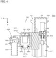
- FIG. 6 is a cross-sectional view in the YZ plane including the second axis 141.
- the multi-axis robot 543 includes a vertical moving saddle 577, a first rotation saddle 593, a second axis motor 579, and a second axis reduction unit 581.
- the vertical moving saddle 577 includes projections 577a, 577b projecting forward at their upper and lower ends.
- the vertical moving saddle 577 has a U-shaped cross-section.
- the first rotation saddle 593 includes a support shaft 580 at the lower end of the first rotation saddle 593.
- the basal end of the first rotation saddle 593 is supported by the projections 577a, 577b.
- the first rotation saddle 593 is disposed so as to extend forward of the vertical moving saddle 577.
- the second axis motor 579 is disposed at the basal end of the first rotation saddle 593 with the output shaft facing upward.
- the second axis reduction unit 581 is directly connected to the second axis motor 579, and is supported by the projection 577a above the vertical moving saddle 577.
- the support shaft 580 is supported by the lower projection 577b via a bearing 583.
- the first arm 101 is supported in front of the first rotation saddle 593.
- the third axis 143 is located in front of the second axis 141, the height of the multi-axis robot 543 and the cleaning apparatus 500 is lowered.
- the shelf plate 514 is provided at the lower part of the cleaning chamber 511, and the cleaning station 515 and the drying station 513 are provided below the shelf plate 514, the loading port 31 and the unloading port can be arranged on the front surface. Therefore, the cleaning apparatus 500 is more freely arranged.
Landscapes
- Engineering & Computer Science (AREA)
- Mechanical Engineering (AREA)
- Robotics (AREA)
- General Engineering & Computer Science (AREA)
- Cleaning By Liquid Or Steam (AREA)
Description
- The present invention relates to a cleaning apparatus. 2. Description of the Background
- A conventional cleaning apparatus includes a cleaning tank in which a plurality of nozzles are arranged at the bottom, a robot hand for gripping a workpiece, and a multi-axis robot facing the cleaning tank (
Japanese Patent No. 4317502 DE 102016005434 A1 discloses a robot cell with a robot cell room with at least one charging frame, at least one robot on which at least one gripping tool is arranged, at least one cleaning station and at least one cleaning medium, thereby characterized in that the robot grips at least one workpiece to be cleaned with the gripping tool and inserts it directly or indirectly into the charging rack and removes it according to the FiFo principle.EP 3636357 A1 discloses a compact versatile cell-type cleaning device and cell-type drying device. - The cleaning apparatus of
Patent Literature 1 includes a robot with a wide range of motion, the installation area of the cleaning apparatus is increased. - An object of the present invention is to provide a compact cleaning apparatus including a robot with a narrow range of motion.
-
Claim 1 of of the present invention provides a cleaning apparatus, including: - a cleaning chamber having a side surface;
- a cleaning station including a cleaning nozzle configured to inject cleaning liquid;
- a drying station including a blow nozzle configured to inject dry air;
- a separation wall partitioning the cleaning chamber into the cleaning station and the drying station;
- a single axis robot including
- a column arranged adjacent to the side surface, the column arranged along an extension of the separation wall,
- a linear guide arranged in the column, the linear guide extending vertically, and
- a vertical moving saddle configured to move vertically along the linear guide;
- an arm portion including
- a first rotation saddle supported by the vertical moving saddle, the first rotation saddle configured to rotate about a second axis extending vertically,
- a first arm supported by the first rotation saddle, the first arm swingable about a third axis extending horizontally, the first arm extending orthogonal to the third axis,
- a second arm supported by the first arm, the second arm configured to rotate about a fourth axis orthogonal to the third axis,
- a second rotation saddle supported by the second arm, the second rotation saddle configured to rotate about a fifth axis orthogonal to the fourth axis, and
- a third rotation saddle supported by the second rotation saddle, the third rotation saddle configured to rotate about a sixth axis orthogonal to the fifth axis; and
- a hand supported by the third rotation saddle to grip a workpiece, wherein the side surface has a loading port, and the hand is extendable toward outside of the loading port through the loading port.
- The cleaning liquid is, for example, an aqueous cleaning liquid. The foreign substances that adhere to the workpiece are, for example, chips or oil.
- Cleaning includes deburring with a high pressure jet.
- The separation wall is arranged in connection with the opposite side of the surface (second side surface) on which the column of the cleaning chamber is installed, and a sufficient gap is provided between the separation wall and the column. Among the spaces inside the cleaning chamber, one space separated by the separation wall is called a cleaning station, and the other space is called a drying station. The area near the column where the separation wall is not installed is called the transfer passage. The transfer passage is continuous with the cleaning station and the drying station.
- The multi-axis robot drives the first to sixth axes simultaneously and can freely move the three-dimensional space. The multi-axis robot is numerically controlled.
- The column has a base plate located on the side of the cleaning chamber. The through hole is formed in the base plate. The linear guide is located on the side of the base plate opposite to the cleaning chamber.
- An arm portion is arranged on a single axis robot. The arm portion is an articulated robot extending in a straight line, and two rotation axes, i.e., a second axis and a third axis, are arranged at the basal end portion thereof. The arm portion is divided into a first arm disposed at the basal end and a second arm disposed at the distal end. The second arm can be rotated about the fourth axis extending along the first arm. Two rotation axes, i. e., the fifth axis and the sixth axis, are arranged at the distal end of the second arm. Motors of each axis are, for example, servo motors, or stepping motors
- The telescopic covers are, for example, bellows. The telescopic cover is arranged on the surface of the base plate on the cleaning chamber side. The telescopic cover is disposed above and below the vertical moving saddles, respectively. The moving end of the respective telescopic cover is fixed to the vertical moving saddles, and the fixed end is fixed to the column. The telescopic cover suppresses the cleaning liquid and foreign matter from entering into the column via the through hole.
- Preferably, the cleaning chamber includes a loading port and an unloading port. The loading port may be located in the cleaning station. The loading port may be located on a wall near the cleaning station, among the walls surrounding the transfer passage. In accordance with the invention, the side surface of the cleaning chamber has a loading port.
- The unloading port may be located at the drying station. The unloading port may be located on a wall near the drying station, among the walls surrounding the transfer passage. In place of the loading port and the unloading port, a single loading/unloading port may be disposed.
- The cleaning apparatus may include an air supply device, which may be a blower or a compressor.
- According to the present invention, a compact cleaning apparatus including a robot with a narrow range of motion is provided.
-
-
FIG.1 is a perspective view of a cleaning apparatus according to a first embodiment with a part cutting out. -
FIG.2 is a longitudinal cross-sectional view of a multi-axis robot according to the first embodiment. -
FIG.3 is a cross-sectional view along III-III inFIG. 2 . -
FIG.4A is a perspective view showing the cleaning apparatus according to the first embodiment in use. -
FIG. 4 B is a cross-sectional view passing through YZ plane showing the cleaning apparatus according to the first embodiment in use. -
FIG. 5 is a perspective view of a cleaning apparatus according to a second embodiment with a part cutting out. -
FIG. 6 is a cross-sectional view along VI plane inFIG. 5 . - The
cleaning apparatus 10 according to the present embodiment will be described with reference toFIG. 1 . Left-right direction as viewed from the front of thecleaning apparatus 10 is defined as X-axis (left is positive from the front), front-rear direction is defined as Y-axis (front is positive), and vertical direction is defined as Z-axis (downward is positive). - The
cleaning apparatus 10 includes acleaning chamber 11, amulti-axis robot 43, and ahand 137. Themulti-axis robot 43 includes asingle axis robot 44 and anarm portion 45. The cleaningchamber 11 is partitioned into a cleaningstation 15, a dryingstation 23, and atransfer passage 35 by aseparation wall 13. - The cleaning
station 15 includes acleaning pipe 19 and a cleaningnozzle 21. The cleaningstation 15 may further include apump 37 and atank 39. Thepump 37 is, for example, a plunger pump, a piston pump, a centrifugal pump, or a gear pump. Thetank 39 stores cleaning liquid. The cleaning liquid stored in thetank 39 is supplied to thepump 37. - The drying
station 23 includes ablow pipe 27 and ablow nozzle 29. The dryingstation 23 may further include ablower 41. - The cleaning
chamber 11 includes atop plate 14, abottom plate 16, a rear surface (side surface) 38, theseparation wall 13, and a loading port 31 (seeFIG. 4A ). The cleaningchamber 11 may include an unloadingport 33, aloading door 34, and an unloadingdoor 40. For example, theloading port 31 is disposed on the left side surface of the cleaningchamber 11, and the unloadingport 33 is disposed on the right side surface of the cleaningchamber 11. Theloading door 34 is, for example, a slide door, to open and close theloading port 31. The unloadingdoor 40 is, for example, a slide door, to open and close the unloadingport 33. - The
separation wall 13 is arranged along the YZ plane in the front of the cleaningchamber 11 at the center in the lateral direction. Preferably, theseparation wall 13 is in contact with thetop plate 14 and thebottom plate 16. The rear end of theseparation wall 13 is apart from therear surface 38 of the cleaningchamber 11. The rear end of theseparation wall 13 and therear surface 38 of the cleaningchamber 11 define thetransfer passage 35. Thetransfer passage 35 is continuous with the cleaningstation 15 and the dryingstation 23. - The cleaning
pipe 19 connects to thepump 37. The cleaningpipe 19 is, for example, U-shaped or O-shaped. The space surrounded by the cleaningpipe 19 is referred to as the cleaningspace 18. Preferably, the cleaningpipe 19 is arranged so that theworkpiece 151, thehand 137 and thearm portion 45 can pass behind the cleaningpipe 19. - A plurality of cleaning
nozzles 21 are disposed on thecleaning pipe 19. The cleaningnozzle 21 has anozzle hole 21a directed to the cleaningspace 18. A plurality of cleaningnozzles 21 are equally spaced, for example, on thecleaning pipe 19. - The
blow pipe 27 connects to ablower 41. Theblow pipe 27 is, for example, U-shaped or O-shaped. The space surrounded by theblow pipe 27 is referred to as a dryingspace 24. Preferably, theblow pipe 27 is disposed so that theworkpiece 151, thehand 137, and thearm portion 45 can pass behind theblow pipe 27. - A plurality of
blow nozzles 29 are disposed on theblow pipe 27. Theblow nozzle 29 has anozzle hole 29a directed to the dryingspace 24. A plurality ofblow nozzles 29 are equally spaced, for example, on theblow pipe 27. - The
transfer passage 35 extends rearward of theseparation wall 13, and is a space continuous with the cleaningstation 15 and the dryingstation 23. - The
multi-axis robot 43 is disposed adjacent to thetransfer passage 35. Themulti-axis robot 43 is disposed, for example, on an extension of theseparation wall 13. - The
single axis robot 44 is movable along afirst axis 139 and is disposed extending vertically to therear surface 38 of the cleaningchamber 11. Thesingle axis robot 44 includes a vertical movingsaddle 77. Thearm portion 45 is a five-axis robot disposed on the vertical movingsaddle 77. - The
multi-axis robot 43 is driven along thefirst axis 139, asecond axis 141, athird axis 143, afourth axis 145, afifth axis 147, and asixth axis 149. Thefirst axis 139 is a translation axis extending in the Z direction. Thesecond axis 141 is a rotation axis extending in the Z direction. Thethird axis 143 is a rotation axis orthogonal to thesecond axis 141. Thefourth axis 145 is a rotation axis orthogonal to thethird axis 143. Thefifth axis 147 is a rotation axis orthogonal to thefourth axis 145. Thesixth axis 149 is a rotation axis orthogonal to thefifth axis 147. -
FIG. 2 shows a longitudinal cross-sectional view of themulti-axis robot 43 along YZ plane passing thesecond axis 141 with thearm portion 45 extending in parallel to the Z direction. As shown inFIG. 2 , thesingle axis robot 44 includes acolumn 46, aside plate 49, abase plate 47, a saddle hole (through hole) 51, a support plate 53, a drivingdevice 67, alinear guide 59, a guide block 61and aslider 63. Thesingle axis robot 44 may include atelescopic cover 75. - The
column 46 is arranged in contact with therear surface 38 of the cleaningchamber 11. Thecolumn 46 is a box body surrounded by thebase plate 47, theside plate 49, and the support plate 53, and has anopening 46a at the rear. Thebase plate 47 is disposed on the front surface of thecolumn 46 and is a part of therear surface 38 of the cleaningchamber 11. Thesaddle hole 51 is disposed in the center of thebase plate 47 and extends in the vertical direction. Theside plates 49 are arranged on the right and left sides of thecolumn 46. - The support plate 53 is disposed in the
opening 46a so as to be separated from thebase plate 47. The support plate 53 is bridged between theside plates 49, for example. The support plate 53 is accurately positioned by, for example, positioning pins. The support plate 53 may be detachable from thecolumn 46. - The support plate 53 may include a
motor support plate 53A and a shaft end support plate 53B. - The
motor support plate 53A is disposed on the upper side of thecolumn 46. Themotor support plate 53A includes amotor bracket 55 and abearing holder 57. Themotor bracket 55 is disposed in front of themotor support plate 53A. The bearingholder 57 is disposed in front of themotor support plate 53A. The bearingholder 57 includes abearing 57a. Themotor support plate 53A is detachable from thecolumn 46. - The shaft end support plate 53B is disposed on the lower side of the
column 46. The shaft end support plate 53B includes abearing holder 58. The bearingholder 58 is disposed in front of the shaft end support plate 53B. The bearingholder 58 includes abearing 58a. The shaft end support plate 53B is detachable from thecolumn 46. - The driving
device 67 is fixed to the support plate 53. The drivingdevice 67 is, for example, a ball screw mechanism. The drivingdevice 67 includes afirst axis motor 69, aball screw 71, and acoupling 73. The drivingdevice 67 is disposed along thefirst axis 139. - The ball screw 71 includes a
nut 72. Both ends of theball screw 71 are supported by thebearings - The
first axis motor 69 includes anoutput shaft 69a, and is supported by themotor bracket 55. Thefirst axis motor 69 is, for example, disposed with theoutput shaft 69a directed in the + Z direction. Thecoupling 73 directly fastens theoutput shaft 69a and theball screw 71. - As shown in
FIG. 3 , thelinear guides 59 are disposed on the rear surface of thebase plate 47, extending in the Z direction. The linear guides 59 are disposed on the left and right sides of thesaddle hole 51, respectively. Theguide block 61 is disposed on thelinear guide 59 and reciprocates on thelinear guide 59. - The
slider 63 is disposed onguide block 61. Theslider 63 is disposed on the front side of the drivingdevice 67 at the rear of thebase plate 47. Theslider 63 has anut holder 65. Thenut holder 65 is disposed on the rear surface of theslider 63. - The
telescopic cover 75 is a bellows. Thetelescopic cover 75 is disposed adjacent to the front surface of thebase plate 47 and between thebase plate 47 and the vertical movingsaddle 77. - The vertical moving
saddle 77 is disposed on the front side of theslider 63 and project into the cleaningchamber 11 through thesaddle hole 51. - As shown in
FIG. 2 , thearm portion 45 includes asecond axis motor 79, a secondaxis reduction unit 81, afirst rotation saddle 93, athird axis motor 95, a thirdaxis reduction gear 97, abearing 99, asupport shaft 107, afirst arm 101, afourth axis motor 103, a fourthaxis reduction unit 105, asecond arm 113, afifth axis motor 115, a fifthaxis reduction unit 117, asupport shaft 119, asecond rotation saddle 129, asixth axis motor 131, a sixthaxis reduction gear 133, and athird rotation saddle 136. - The
second axis motor 79 includes an output shaft 79a, and is disposed on the rear side of the vertical movingsaddle 77. - The second
axis reduction unit 81 includes a drivingpulley 85, an endlesstoothed belt 87, a drivenpulley 89, and a second axisfinal reduction gear 91. The second axisfinal reduction gear 91 includes aninput shaft 91a, and anoutput shaft 91b. Theoutput shaft 91b is aligned with thesecond axis 141. Theoutput shaft 91b is coaxial with theinput shaft 91a. The second axisfinal reduction gear 91 is preferably a non-backlash reduction gear. The drivingpulley 85 is fixed to the output shaft 79a. The drivenpulley 89 is fixed to theinput shaft 91a. The endlesstoothed belt 87 is mounted across the drivingpulley 85 and the drivenpulley 89. - The
first rotation saddle 93 is fixed to theoutput shaft 91b. Thefirst rotation saddle 93 is supported by the vertical movingsaddle 77 so as to be rotatable about thesecond axis 141. - The
third axis motor 95 includes anoutput shaft 95a, and is disposed at the basal end of thefirst arm 101. Thethird axis motor 95 is connected to the thirdaxis reduction gear 97. - The third
axis reduction gear 97 includes aninput shaft 97a and anoutput shaft 97b, and is disposed on one side of thefirst rotation saddle 93. Theinput shaft 97a is coaxial with thethird axis 143. Theinput shaft 97a is fixed to theoutput shaft 95a. Thebearing 99 is disposed on the side surface of thefirst rotation saddle 93 opposite to the thirdaxis reduction gear 97. - The
first arm 101 includes asupport shaft 107. Thesupport shaft 107 is coaxial with thethird axis 143, and is supported by thebearing 99. Both ends of thefirst arm 101 are supported by theoutput shaft 95a and thebearing 99. Thefirst arm 101 is swingable about thethird axis 143. - The
fourth axis motor 103 includes anoutput shaft 103a, and is disposed at the distal end of thefirst arm 101. - The fourth
axis reduction unit 105 includes asmall gear 108, alarge gear 109, and a fourth axisfinal reduction gear 111. The fourth axisfinal reduction gear 111 includes aninput shaft 111a and anoutput shaft 111b, and is disposed at the distal end of thefirst arm 101. Thesmall gear 108 is fixed to theoutput shaft 103a. Thelarge gear 109 is fixed to theinput shaft 111a, and meshes with thesmall gear 108. Theoutput shaft 111b is coaxial with thefourth axis 145. Preferably, the fourth axisfinal reduction gear 111 is a non-backlash reduction gear. - The
second arm 113 extends along thefourth axis 145, and is fixed to theoutput shaft 111b. Thesecond arm 113 includes a trunnion-type support portion 118 and asupport shaft 119. Thesupport portion 118 is U-shaped, and is disposed on the distal end portion of thesecond arm 113. Thesupport shaft 119 is arranged inside the -Y direction of thesupport portion 118 to be aligned with thefifth axis 147. - The
fifth axis motor 115 has anoutput shaft 115a, and is disposed at the basal end of thesecond arm 113. - The fifth
axis reduction unit 117 includes a drivingpulley 121, atoothed belt 123, a drivenpulley 125, and a fifth axisfinal reduction gear 127. The fifth axisfinal reduction gear 127 includes an input shaft 127a and anoutput shaft 127b. For example, the input shaft 127a is coaxial with theoutput shaft 127b. Preferably, the fifth axisfinal reduction gear 127 is a non-backlash reduction gear. The fifth axisfinal reduction gear 127 is arranged inside the +Y direction of thesupport portion 118 to be aligned with thefifth axis 147. - The driving
pulley 121 is fixed to theoutput shaft 115a. The drivenpulley 125 is fixed to the input shaft 127a. Thetoothed belt 123 is mounted across the drivingpulley 121 and the drivenpulley 125. - The
bearing 135, thesixth axis motor 131 and the sixthaxis reduction gear 133 are disposed in thesecond rotation saddle 129. Thesupport shaft 119 is supported by thebearing 135. Thesecond rotation saddle 129 is fixed to theoutput shaft 127b. Both ends of thesecond rotation saddle 129 are supported by theoutput shaft 127b and thesupport shaft 119, and thesecond rotation saddle 129 is swingably disposed about thefifth axis 147. - The
sixth axis motor 131 includes anoutput shaft 131a, and is disposed at the distal end of thesecond rotation saddle 129. Theoutput shaft 131a is aligned with thesixth axis 149. - The sixth
axis reduction gear 133 includes aninput shaft 133a and anoutput shaft 133b. Theoutput shaft 133b is coaxial with theinput shaft 133a. Theinput shaft 133a is directly coupled with theoutput shaft 131a. Theoutput shaft 133b is coaxical with thesixth axis 149. - The
third rotation saddle 136 is fixed to theoutput shaft 133b. - The
hand 137 is disposed on the distal end surface of thethird rotation saddle 136. Thehand 137 includes, for example, a fixedclaw 137a and amovable claw 137b. Themovable claw 137b is disposed facing the fixedclaw 137a, and reciprocates in a direction toward the fixedclaw 137a. For example, thehand 137 is driven by compressed air. - Referring to
FIGs. 4A and4B , a method of cleaning theworkpiece 151 by using thecleaning apparatus 10 will be described. First, theloading door 34 is opened. Next, as shown inFIG. 4A , themulti-axis robot 43 moves thehand 137 through theloading port 31 to the outside of thecleaning apparatus 10. Thehand 137 grips theworkpiece 151 outside the cleaningchamber 11. Themulti-axis robot 43 carries theworkpiece 151 into the inside of the cleaningchamber 11 through theloading port 31 along apath 153 with theworkpiece 151 gripped. Then, theloading door 34 is closed. - The
multi-axis robot 43 moves theworkpiece 151 to the cleaningstation 15. Thepump 37 supplies cleaning liquid to thecleaning pipe 19. The cleaningnozzle 21 injects the cleaning liquid into the cleaningspace 18. Next, themulti-axis robot 43 performs cleaning while holding theworkpiece 151. Themulti-axis robot 43 positions theworkpiece 151 above the cleaningspace 18. As shown inFig. 4B , themulti-axis robot 43 moves theworkpiece 151 along apath 155 in the cleaningspace 18. Ajet 25 impinges on the cleaning target location of theworkpiece 151. - The
path 155 shown inFIG. 4B first moves toward the +Z-direction by theheight 157 of theworkpiece 151. Next, it moves by a quarter of anarrangement interval 159 of the cleaningnozzle 21 toward the -Y direction. Next, theworkpiece 151 is moved by theheight 157 toward the -Z direction. Next, it moves by a quarter of thearrangement interval 159 of the cleaningnozzle 21 toward the -Y direction. By repeating this operation four times, the surface of theworkpiece 151 can be cleaned substantially uniformly. - The
path 155 is merely an example, and other path may be adopted. - After cleaning, the
multi-axis robot 43 moves theworkpiece 151 to the dryingstation 23 through thetransfer passage 35. Theblower 41 supplies dry air to theblow nozzle 29. The drying method is substantially the same as the cleaning method. Next, the unloadingdoor 40 is opened. Themulti-axis robot 43 moves theworkpiece 151 to an unloading position outside the cleaningchamber 11 through the unloadingport 33. Themulti-axis robot 43 releases theworkpiece 151 from thehand 137. Thearm portion 45 returns to thetransfer passage 35 through the unloadingport 33. Finally, the unloadingdoor 40 is closed. - As shown in
FIG. 5 , thecleaning apparatus 500 of the present embodiment includes acleaning chamber 511, amulti-axis robot 543, aseparation wall 513, ashelf plate 514, a cleaningstation 515, and a dryingstation 523. Themulti-axis robot 543 includes asingle axis robot 44 and anarm portion 545. Although not shown inFIG. 5 , a hand is disposed at the distal end of thearm portion 545. - The cleaning
station 515 and the dryingstation 523 are disposed below theshelf plate 514. Theseparation wall 513 partitions the lower portion of theshelf plate 514 into the cleaningstation 515 and the dryingstation 523. - The
shelf plate 514 is disposed horizontally along the front surface (second side surface). The rear end of theshelf plate 514 is separated from therear surface 38 of the cleaningchamber 11. A gap is provided between the rear end of theshelf plate 514 and the multi-axis robot 544 so as to freely pivot in a state where thearm portion 545 is folded. - The
separation wall 513 is in contact with theshelf plate 514, thebottom plate 16, and the front surface. The rear end of theseparation wall 513 is located at the same position in the front-rear direction as the rear end of theshelf plate 514. - A
cleaning pipe 519 is disposed along the ZX plane at the rear end of the cleaningstation 515. Thecleaning pipe 519 is, for example, in O-shape. Cleaningnozzles 21 are disposed on the entire circumference of the inner periphery of thecleaning pipe 519. Thenozzle hole 21a of the cleaningnozzle 21 is faced toward the inside of thecleaning pipe 519. - The
blow pipe 527 is disposed along the ZX plane at the rear end of the dryingstation 523. Theblow pipe 527 is, for example, in O-shape. Blownozzles 29 are disposed on the entire circumference of the inner periphery of theblow pipe 527. Thenozzle hole 29a of theblow nozzle 29 is faced toward the inside of theblow pipe 527. - The loading port and the unloading port are located above the
shelf plate 514. The loading port (not shown) and the unloadingport 33 are located, for example, on the right side surface and the left side surface, respectively. Theloading port 31 also serving as the unloading port may be located on the front surface. - Each portion of the
arm portion 545 is rotated about thesecond axis 141, thethird axis 143, thefourth axis 145, thefifth axis 147, and thesixth axis 149. Thesecond axis 141 extends in the Z direction. Thethird axis 143 extends horizontally. Thethird axis 143 is located in front of thesecond axis 141 and does not intersect thesecond axis 141. -
FIG. 6 is a cross-sectional view in the YZ plane including thesecond axis 141. As shown inFIG. 6 , themulti-axis robot 543 includes a vertical movingsaddle 577, afirst rotation saddle 593, asecond axis motor 579, and a secondaxis reduction unit 581. The vertical movingsaddle 577 includesprojections saddle 577 has a U-shaped cross-section. - The
first rotation saddle 593 includes asupport shaft 580 at the lower end of thefirst rotation saddle 593. The basal end of thefirst rotation saddle 593 is supported by theprojections first rotation saddle 593 is disposed so as to extend forward of the vertical movingsaddle 577. Thesecond axis motor 579 is disposed at the basal end of thefirst rotation saddle 593 with the output shaft facing upward. The secondaxis reduction unit 581 is directly connected to thesecond axis motor 579, and is supported by theprojection 577a above the vertical movingsaddle 577. Thesupport shaft 580 is supported by thelower projection 577b via abearing 583. - The
first arm 101 is supported in front of thefirst rotation saddle 593. - According to the present embodiment, since the
third axis 143 is located in front of thesecond axis 141, the height of themulti-axis robot 543 and thecleaning apparatus 500 is lowered. In addition, since theshelf plate 514 is provided at the lower part of thecleaning chamber 511, and the cleaningstation 515 and the dryingstation 513 are provided below theshelf plate 514, theloading port 31 and the unloading port can be arranged on the front surface. Therefore, thecleaning apparatus 500 is more freely arranged. -
- 10, 500
- Cleaning apparatus
- 11, 511
- Cleaning chamber
- 13, 513
- Separation wall
- 15, 515
- Cleaning station
- 21
- Cleaning nozzle
- 23, 523
- Drying station
- 29
- Blow nozzle
- 38
- Back surface (Side)
- 46
- Column
- 59
- Linear guide
- 77
- Vertical moving saddle
- 93
- First rotation saddle
- 101
- First arm
- 113
- Second arm
- 129
- Second rotation saddle
- 136
- Third rotation saddle
- 137
- Hand
- 139
- First axis
- 141
- Second axis
- 143
- Third axis
- 145
- Fourth axis
- 147
- Fifth axis
- 149
- Sixth axis
- 151
- Workpiece
Claims (8)
- A cleaning apparatus, comprising:a cleaning chamber (11, 511) having a side surface (38);a cleaning station (15, 515)including a cleaning nozzle (21) configured to inject cleaning liquid;a drying station (23, 523) {44} including a blow nozzle (29) configured to inject dry air;a separation wall (13) partitioning the cleaning chamber (11) into the cleaning station (15) and the drying station (23);a single axis robot (44) includinga column (46) arranged adjacent to the side surface (38), the column (46) arranged along an extension of the separation wall (13),a linear guide (59) arranged in the column (46), the linear guide (59) extending vertically, anda vertical moving saddle (77) configured to move vertically along the linear guide (59);an arm portion (45, 545) includinga first rotation saddle (93) supported by the vertical moving saddle (77), the first rotation saddle (93) configured to rotate about a second axis (141) extending vertically,a first arm (101) supported by the first rotation saddle (93), the first arm (101) swingable about a third axis (143) extending horizontally, the first arm (101) extending orthogonal to the third axis (143),a second arm (113) supported by the first arm (101), the second arm (113) configured to rotate about a fourth axis (145) orthogonal to the third axis (143),a second rotation saddle (129) supported by the second arm (113), the second rotation saddle (129) configured to rotate about a fifth axis (147) orthogonal to the fourth axis (145), anda third rotation saddle (136) supported by the second rotation saddle (129), the third rotation saddle (136) configured to rotate about a sixth axis (149) orthogonal to the fifth axis (147); anda hand (137) supported by the third rotation saddle (136) to grip a workpiece (151); whereinthe side surface (38) has a loading port (31), andthe hand (137) is extendable toward outside of the loading port (31) through the loading port (31).
- The cleaning apparatus according to claim 1, whereinthe single axis robot (44) includesa driving device (67) configured to drive the vertical moving saddle (77), anda telescopic cover (75) arranged on an outside surface of the column (46) to face the first rotation saddle (93), the telescopic cover (75) covering a gap between the column (46) and the vertical moving saddle (77),the linear guide (59) and the driving device (67) are arranged inside the column (46), andthe telescopic cover (75) shields the linear guide (59) and the driving device (67) from the cleaning chamber (11).
- The cleaning apparatus according to claim 1 or 2, whereinthe column (46) is a hollow box shaped, and has a through hole (51) arranged on the cleaning chamber (11) side along the linear guide (59), andthe vertical moving saddle (77) includes a slider (63) arranged in the column (46) to slide on the linear guide (59).
- The cleaning apparatus according to any one of claims 1 to 3, whereinthe cleaning chamber (11) includes a bottom plate (16) and a top plate (14), andthe separation wall (13) extends from the bottom plate (16) to the top plate (14).
- The cleaning apparatus according to any one of claims 1 to 4, wherein
the separation wall (13) is arranged to be in contact with a second side surface of the cleaning chamber (11) opposite to the side surface (38), and away from the column (46) such that the arm portion (45) is configured to rotate. - The cleaning apparatus according to any one of claims 1 to 5, whereinthe cleaning station (15) includes a U-shaped or O-shaped cleaning pipe (19) arranged horizontally, the cleaning pipe (19) including a cleaning nozzle (21),the drying station (23) includes a U-shaped or O-shaped blow pipe (27) arranged horizontally, the blow pipe (27) including a blow nozzle (29),the cleaning pipe (19) includes a plurality of nozzle holes (21) directed toward an inside of the cleaning pipe (19), andthe blow pipe (27) includes a plurality of nozzle holes (29a) directed toward an inside of the blow pipe (27).
- The cleaning apparatus according to claim 1,wherein the separation wall (513) is in contact with a second side surface of the cleaning chamber (511), the second side surface located opposite to the side surface (38), the separation wall (513) located away from the column (46) with a gap so that the arm portion (545) is rotatable,the cleaning chamber (511) includesa shelf plate (514) arranged in contact with the second side surface, anda bottom plate (16),the cleaning station (515) and the drying station (523) are arranged below the shelf plate (514),the separation wall (513) extends from the bottom plate (16) to the shelf plate (514), andthe loading port (31) is located above the shelf plate (514).
- The cleaning apparatus according to claim 7, whereinthe cleaning station (515) includes a U-shaped or O-shaped cleaning pipe (519), the cleaning pipe (519) including a cleaning nozzle (21) arranged at an entrance of the cleaning station (515) on a vertical plane,the drying station (523) includes a U-shaped or O-shaped blow pipe (527), the blow pipe (527) including a blow nozzle (29) arranged at an entrance of the drying station (523) on a vertical plane, andthe blow nozzle (29) includes a plurality of nozzle holes (29a) directed toward an inside of the blow pipe (527).
Applications Claiming Priority (1)
| Application Number | Priority Date | Filing Date | Title |
|---|---|---|---|
| JP2019133813 | 2019-07-19 |
Publications (2)
| Publication Number | Publication Date |
|---|---|
| EP3766591A1 EP3766591A1 (en) | 2021-01-20 |
| EP3766591B1 true EP3766591B1 (en) | 2023-05-24 |
Family
ID=71409090
Family Applications (1)
| Application Number | Title | Priority Date | Filing Date |
|---|---|---|---|
| EP20181045.4A Active EP3766591B1 (en) | 2019-07-19 | 2020-06-19 | Cleaning apparatus |
Country Status (4)
| Country | Link |
|---|---|
| US (1) | US11491515B2 (en) |
| EP (1) | EP3766591B1 (en) |
| JP (1) | JP6934091B2 (en) |
| CN (1) | CN112238080B (en) |
Families Citing this family (7)
| Publication number | Priority date | Publication date | Assignee | Title |
|---|---|---|---|---|
| CN113910297B (en) * | 2021-10-21 | 2022-12-20 | 福州大学 | Automatic cleaning machine and cleaning method for ABB robot mechanical arm |
| CN115672822B (en) * | 2022-10-28 | 2025-02-28 | 青岛海鼎通讯技术有限公司 | Mobile phone back panel cleaning machine with turret and cleaning method |
| CN115772644A (en) * | 2022-11-04 | 2023-03-10 | 武汉乙元兴科技有限公司 | Metal surface fingerprint-free treatment process |
| CN115625302A (en) * | 2022-11-28 | 2023-01-20 | 优铸科技(北京)有限公司 | Sand cleaning device and sand cleaning method |
| FR3140787A1 (en) * | 2023-05-03 | 2024-04-19 | Aisprid | ROBOT WITH AN ARTICULATED ARM FOR AGRICULTURE |
| US20260060492A1 (en) * | 2024-08-29 | 2026-03-05 | Clutterbot, Inc. | Sanitizing station for tidying robot |
| JP7828108B1 (en) * | 2024-12-23 | 2026-03-11 | 森合精機株式会社 | Cleaning systems and equipment |
Family Cites Families (16)
| Publication number | Priority date | Publication date | Assignee | Title |
|---|---|---|---|---|
| JP4911810B2 (en) * | 2000-06-23 | 2012-04-04 | コマツNtc株式会社 | Workpiece grinding apparatus and grinding method |
| JP3459632B2 (en) * | 2000-11-27 | 2003-10-20 | 株式会社石井表記 | Substrate cleaning device |
| US7386365B2 (en) * | 2004-05-04 | 2008-06-10 | Intuitive Surgical, Inc. | Tool grip calibration for robotic surgery |
| JP4317502B2 (en) | 2004-08-10 | 2009-08-19 | 株式会社ジェイピーシー | Machine parts cleaning equipment |
| DE102007053897A1 (en) | 2007-11-12 | 2009-05-20 | Boos Reinigungsanlagen Gmbh | Washer system for rectangular boxes, comprises conveyor belt for conveying rectangular boxes, and rail shaped height adjustable blank rod is provided, which is arranged above rectangular boxes |
| JP6607661B2 (en) * | 2013-08-09 | 2019-11-20 | 日本電産サンキョー株式会社 | Horizontal articulated robot |
| US20150306770A1 (en) * | 2014-04-25 | 2015-10-29 | Mittal Nimish | Detachable robotic arm having interference detection system |
| DE102015011511A1 (en) | 2015-09-03 | 2017-03-09 | Werner Meissner | Device for an industrial cleaning system |
| US10687683B2 (en) | 2016-03-24 | 2020-06-23 | Martin A. Alpert | Washing or washing/sterilizing and drying or drying/sterilizing with optional independent sterilization apparatus with robotic arms |
| DE102016005434A1 (en) | 2016-05-06 | 2017-11-09 | Sk-Technologies Ug (Haftungsbeschränkt) | Robot cell for workpiece cleaning |
| CN105922241A (en) * | 2016-06-24 | 2016-09-07 | 无锡市宇正铁路油封制造有限公司 | Dual-face and dual-guiding-rail five-axis manipulator with counterweight |
| JP6608774B2 (en) | 2016-07-22 | 2019-11-20 | 株式会社スギノマシン | Feed base device |
| JP6688204B2 (en) * | 2016-10-26 | 2020-04-28 | 株式会社スギノマシン | Link type articulated robot |
| US10207411B2 (en) | 2017-02-01 | 2019-02-19 | Toyota Research Institute, Inc. | Systems and methods for servicing a vehicle |
| CN108161920A (en) * | 2017-12-01 | 2018-06-15 | 苏州科爱佳自动化科技有限公司 | A kind of contractile running gear of manipulator |
| JP7176823B2 (en) * | 2018-10-09 | 2022-11-22 | 株式会社スギノマシン | CLEANING DEVICE AND METHOD FOR CLEANING AND DRYING OBJECT |
-
2020
- 2020-06-18 JP JP2020105415A patent/JP6934091B2/en active Active
- 2020-06-18 US US16/904,973 patent/US11491515B2/en active Active
- 2020-06-19 EP EP20181045.4A patent/EP3766591B1/en active Active
- 2020-06-23 CN CN202010582918.7A patent/CN112238080B/en active Active
Also Published As
| Publication number | Publication date |
|---|---|
| EP3766591A1 (en) | 2021-01-20 |
| US20210016328A1 (en) | 2021-01-21 |
| CN112238080A (en) | 2021-01-19 |
| JP6934091B2 (en) | 2021-09-08 |
| US11491515B2 (en) | 2022-11-08 |
| JP2021016857A (en) | 2021-02-15 |
| CN112238080B (en) | 2022-07-29 |
Similar Documents
| Publication | Publication Date | Title |
|---|---|---|
| EP3766591A1 (en) | Cleaning apparatus | |
| KR102401174B1 (en) | Cleaning apparatus and cleaning method | |
| KR101948964B1 (en) | Cleaning apparatus | |
| US6884009B2 (en) | Machine tool | |
| EP2977154B1 (en) | Feeding device and object driving device | |
| CN103370167B (en) | machine tool | |
| CN1744966B (en) | Pillar mobile machine with concealed machining space | |
| JP2004532741A (en) | Machine Tools | |
| KR20100074087A (en) | Machine tool | |
| WO2018047301A1 (en) | Machine tool | |
| JP2008260120A (en) | Handling manipulator device | |
| JP3749105B2 (en) | Spray blow equipment for forging press | |
| JP7069327B2 (en) | Machine Tools | |
| JP6818825B1 (en) | Cleaning machine and cleaning method | |
| JP6637989B2 (en) | Machining system | |
| JP2021010875A (en) | Washing machine and washing method | |
| JPH03170249A (en) | Dust collecting device for wood working machine and the like | |
| CN115647936A (en) | Multi-process linkage integrated equipment for aluminum die castings | |
| KR20220152697A (en) | Workpiece Loading and Unloading Apparatus for CNC Machine Tool Having Cleaning Assembly | |
| JPS61101280A (en) | Cleaning method and cleaning equipment | |
| KR20220152695A (en) | Workpiece Loading and Unloading Apparatus for CNC Machine Tool Having Elevating Type Work Assembly |
Legal Events
| Date | Code | Title | Description |
|---|---|---|---|
| PUAI | Public reference made under article 153(3) epc to a published international application that has entered the european phase |
Free format text: ORIGINAL CODE: 0009012 |
|
| STAA | Information on the status of an ep patent application or granted ep patent |
Free format text: STATUS: REQUEST FOR EXAMINATION WAS MADE |
|
| 17P | Request for examination filed |
Effective date: 20200619 |
|
| AK | Designated contracting states |
Kind code of ref document: A1 Designated state(s): AL AT BE BG CH CY CZ DE DK EE ES FI FR GB GR HR HU IE IS IT LI LT LU LV MC MK MT NL NO PL PT RO RS SE SI SK SM TR |
|
| AX | Request for extension of the european patent |
Extension state: BA ME |
|
| RIC1 | Information provided on ipc code assigned before grant |
Ipc: F26B 21/00 20060101ALI20221019BHEP Ipc: B25J 9/04 20060101ALI20221019BHEP Ipc: B25J 5/02 20060101ALI20221019BHEP Ipc: B25J 11/00 20060101ALI20221019BHEP Ipc: B08B 13/00 20060101ALI20221019BHEP Ipc: B08B 5/02 20060101ALI20221019BHEP Ipc: B08B 3/02 20060101AFI20221019BHEP |
|
| RAP3 | Party data changed (applicant data changed or rights of an application transferred) |
Owner name: SUGINO MACHINE LIMITED |
|
| GRAP | Despatch of communication of intention to grant a patent |
Free format text: ORIGINAL CODE: EPIDOSNIGR1 |
|
| STAA | Information on the status of an ep patent application or granted ep patent |
Free format text: STATUS: GRANT OF PATENT IS INTENDED |
|
| INTG | Intention to grant announced |
Effective date: 20221223 |
|
| GRAS | Grant fee paid |
Free format text: ORIGINAL CODE: EPIDOSNIGR3 |
|
| GRAA | (expected) grant |
Free format text: ORIGINAL CODE: 0009210 |
|
| STAA | Information on the status of an ep patent application or granted ep patent |
Free format text: STATUS: THE PATENT HAS BEEN GRANTED |
|
| AK | Designated contracting states |
Kind code of ref document: B1 Designated state(s): AL AT BE BG CH CY CZ DE DK EE ES FI FR GB GR HR HU IE IS IT LI LT LU LV MC MK MT NL NO PL PT RO RS SE SI SK SM TR |
|
| REG | Reference to a national code |
Ref country code: GB Ref legal event code: FG4D |
|
| REG | Reference to a national code |
Ref country code: CH Ref legal event code: EP |
|
| REG | Reference to a national code |
Ref country code: DE Ref legal event code: R096 Ref document number: 602020011028 Country of ref document: DE |
|
| REG | Reference to a national code |
Ref country code: AT Ref legal event code: REF Ref document number: 1569200 Country of ref document: AT Kind code of ref document: T Effective date: 20230615 |
|
| REG | Reference to a national code |
Ref country code: IE Ref legal event code: FG4D |
|
| REG | Reference to a national code |
Ref country code: LT Ref legal event code: MG9D |
|
| REG | Reference to a national code |
Ref country code: NL Ref legal event code: MP Effective date: 20230524 |
|
| REG | Reference to a national code |
Ref country code: AT Ref legal event code: MK05 Ref document number: 1569200 Country of ref document: AT Kind code of ref document: T Effective date: 20230524 |
|
| PG25 | Lapsed in a contracting state [announced via postgrant information from national office to epo] |
Ref country code: SE Free format text: LAPSE BECAUSE OF FAILURE TO SUBMIT A TRANSLATION OF THE DESCRIPTION OR TO PAY THE FEE WITHIN THE PRESCRIBED TIME-LIMIT Effective date: 20230524 Ref country code: PT Free format text: LAPSE BECAUSE OF FAILURE TO SUBMIT A TRANSLATION OF THE DESCRIPTION OR TO PAY THE FEE WITHIN THE PRESCRIBED TIME-LIMIT Effective date: 20230925 Ref country code: NO Free format text: LAPSE BECAUSE OF FAILURE TO SUBMIT A TRANSLATION OF THE DESCRIPTION OR TO PAY THE FEE WITHIN THE PRESCRIBED TIME-LIMIT Effective date: 20230824 Ref country code: NL Free format text: LAPSE BECAUSE OF FAILURE TO SUBMIT A TRANSLATION OF THE DESCRIPTION OR TO PAY THE FEE WITHIN THE PRESCRIBED TIME-LIMIT Effective date: 20230524 Ref country code: ES Free format text: LAPSE BECAUSE OF FAILURE TO SUBMIT A TRANSLATION OF THE DESCRIPTION OR TO PAY THE FEE WITHIN THE PRESCRIBED TIME-LIMIT Effective date: 20230524 Ref country code: AT Free format text: LAPSE BECAUSE OF FAILURE TO SUBMIT A TRANSLATION OF THE DESCRIPTION OR TO PAY THE FEE WITHIN THE PRESCRIBED TIME-LIMIT Effective date: 20230524 |
|
| PG25 | Lapsed in a contracting state [announced via postgrant information from national office to epo] |
Ref country code: RS Free format text: LAPSE BECAUSE OF FAILURE TO SUBMIT A TRANSLATION OF THE DESCRIPTION OR TO PAY THE FEE WITHIN THE PRESCRIBED TIME-LIMIT Effective date: 20230524 Ref country code: PL Free format text: LAPSE BECAUSE OF FAILURE TO SUBMIT A TRANSLATION OF THE DESCRIPTION OR TO PAY THE FEE WITHIN THE PRESCRIBED TIME-LIMIT Effective date: 20230524 Ref country code: LV Free format text: LAPSE BECAUSE OF FAILURE TO SUBMIT A TRANSLATION OF THE DESCRIPTION OR TO PAY THE FEE WITHIN THE PRESCRIBED TIME-LIMIT Effective date: 20230524 Ref country code: LT Free format text: LAPSE BECAUSE OF FAILURE TO SUBMIT A TRANSLATION OF THE DESCRIPTION OR TO PAY THE FEE WITHIN THE PRESCRIBED TIME-LIMIT Effective date: 20230524 Ref country code: IS Free format text: LAPSE BECAUSE OF FAILURE TO SUBMIT A TRANSLATION OF THE DESCRIPTION OR TO PAY THE FEE WITHIN THE PRESCRIBED TIME-LIMIT Effective date: 20230924 Ref country code: HR Free format text: LAPSE BECAUSE OF FAILURE TO SUBMIT A TRANSLATION OF THE DESCRIPTION OR TO PAY THE FEE WITHIN THE PRESCRIBED TIME-LIMIT Effective date: 20230524 Ref country code: GR Free format text: LAPSE BECAUSE OF FAILURE TO SUBMIT A TRANSLATION OF THE DESCRIPTION OR TO PAY THE FEE WITHIN THE PRESCRIBED TIME-LIMIT Effective date: 20230825 |
|
| PG25 | Lapsed in a contracting state [announced via postgrant information from national office to epo] |
Ref country code: FI Free format text: LAPSE BECAUSE OF FAILURE TO SUBMIT A TRANSLATION OF THE DESCRIPTION OR TO PAY THE FEE WITHIN THE PRESCRIBED TIME-LIMIT Effective date: 20230524 |
|
| PG25 | Lapsed in a contracting state [announced via postgrant information from national office to epo] |
Ref country code: SK Free format text: LAPSE BECAUSE OF FAILURE TO SUBMIT A TRANSLATION OF THE DESCRIPTION OR TO PAY THE FEE WITHIN THE PRESCRIBED TIME-LIMIT Effective date: 20230524 |
|
| PG25 | Lapsed in a contracting state [announced via postgrant information from national office to epo] |
Ref country code: SM Free format text: LAPSE BECAUSE OF FAILURE TO SUBMIT A TRANSLATION OF THE DESCRIPTION OR TO PAY THE FEE WITHIN THE PRESCRIBED TIME-LIMIT Effective date: 20230524 Ref country code: SK Free format text: LAPSE BECAUSE OF FAILURE TO SUBMIT A TRANSLATION OF THE DESCRIPTION OR TO PAY THE FEE WITHIN THE PRESCRIBED TIME-LIMIT Effective date: 20230524 Ref country code: RO Free format text: LAPSE BECAUSE OF FAILURE TO SUBMIT A TRANSLATION OF THE DESCRIPTION OR TO PAY THE FEE WITHIN THE PRESCRIBED TIME-LIMIT Effective date: 20230524 Ref country code: EE Free format text: LAPSE BECAUSE OF FAILURE TO SUBMIT A TRANSLATION OF THE DESCRIPTION OR TO PAY THE FEE WITHIN THE PRESCRIBED TIME-LIMIT Effective date: 20230524 Ref country code: DK Free format text: LAPSE BECAUSE OF FAILURE TO SUBMIT A TRANSLATION OF THE DESCRIPTION OR TO PAY THE FEE WITHIN THE PRESCRIBED TIME-LIMIT Effective date: 20230524 Ref country code: CZ Free format text: LAPSE BECAUSE OF FAILURE TO SUBMIT A TRANSLATION OF THE DESCRIPTION OR TO PAY THE FEE WITHIN THE PRESCRIBED TIME-LIMIT Effective date: 20230524 |
|
| REG | Reference to a national code |
Ref country code: CH Ref legal event code: PL |
|
| REG | Reference to a national code |
Ref country code: BE Ref legal event code: MM Effective date: 20230630 |
|
| REG | Reference to a national code |
Ref country code: DE Ref legal event code: R097 Ref document number: 602020011028 Country of ref document: DE |
|
| PG25 | Lapsed in a contracting state [announced via postgrant information from national office to epo] |
Ref country code: MC Free format text: LAPSE BECAUSE OF FAILURE TO SUBMIT A TRANSLATION OF THE DESCRIPTION OR TO PAY THE FEE WITHIN THE PRESCRIBED TIME-LIMIT Effective date: 20230524 |
|
| PG25 | Lapsed in a contracting state [announced via postgrant information from national office to epo] |
Ref country code: MC Free format text: LAPSE BECAUSE OF FAILURE TO SUBMIT A TRANSLATION OF THE DESCRIPTION OR TO PAY THE FEE WITHIN THE PRESCRIBED TIME-LIMIT Effective date: 20230524 |
|
| PG25 | Lapsed in a contracting state [announced via postgrant information from national office to epo] |
Ref country code: LU Free format text: LAPSE BECAUSE OF NON-PAYMENT OF DUE FEES Effective date: 20230619 |
|
| REG | Reference to a national code |
Ref country code: IE Ref legal event code: MM4A |
|
| PG25 | Lapsed in a contracting state [announced via postgrant information from national office to epo] |
Ref country code: LU Free format text: LAPSE BECAUSE OF NON-PAYMENT OF DUE FEES Effective date: 20230619 |
|
| PLBE | No opposition filed within time limit |
Free format text: ORIGINAL CODE: 0009261 |
|
| STAA | Information on the status of an ep patent application or granted ep patent |
Free format text: STATUS: NO OPPOSITION FILED WITHIN TIME LIMIT |
|
| PG25 | Lapsed in a contracting state [announced via postgrant information from national office to epo] |
Ref country code: IE Free format text: LAPSE BECAUSE OF NON-PAYMENT OF DUE FEES Effective date: 20230619 |
|
| PG25 | Lapsed in a contracting state [announced via postgrant information from national office to epo] |
Ref country code: IE Free format text: LAPSE BECAUSE OF NON-PAYMENT OF DUE FEES Effective date: 20230619 Ref country code: CH Free format text: LAPSE BECAUSE OF NON-PAYMENT OF DUE FEES Effective date: 20230630 |
|
| 26N | No opposition filed |
Effective date: 20240227 |
|
| PG25 | Lapsed in a contracting state [announced via postgrant information from national office to epo] |
Ref country code: SI Free format text: LAPSE BECAUSE OF FAILURE TO SUBMIT A TRANSLATION OF THE DESCRIPTION OR TO PAY THE FEE WITHIN THE PRESCRIBED TIME-LIMIT Effective date: 20230524 |
|
| PG25 | Lapsed in a contracting state [announced via postgrant information from national office to epo] |
Ref country code: SI Free format text: LAPSE BECAUSE OF FAILURE TO SUBMIT A TRANSLATION OF THE DESCRIPTION OR TO PAY THE FEE WITHIN THE PRESCRIBED TIME-LIMIT Effective date: 20230524 Ref country code: BE Free format text: LAPSE BECAUSE OF NON-PAYMENT OF DUE FEES Effective date: 20230630 |
|
| PG25 | Lapsed in a contracting state [announced via postgrant information from national office to epo] |
Ref country code: BG Free format text: LAPSE BECAUSE OF FAILURE TO SUBMIT A TRANSLATION OF THE DESCRIPTION OR TO PAY THE FEE WITHIN THE PRESCRIBED TIME-LIMIT Effective date: 20230524 |
|
| PG25 | Lapsed in a contracting state [announced via postgrant information from national office to epo] |
Ref country code: BG Free format text: LAPSE BECAUSE OF FAILURE TO SUBMIT A TRANSLATION OF THE DESCRIPTION OR TO PAY THE FEE WITHIN THE PRESCRIBED TIME-LIMIT Effective date: 20230524 |
|
| GBPC | Gb: european patent ceased through non-payment of renewal fee |
Effective date: 20240619 |
|
| PG25 | Lapsed in a contracting state [announced via postgrant information from national office to epo] |
Ref country code: GB Free format text: LAPSE BECAUSE OF NON-PAYMENT OF DUE FEES Effective date: 20240619 |
|
| PGFP | Annual fee paid to national office [announced via postgrant information from national office to epo] |
Ref country code: DE Payment date: 20250618 Year of fee payment: 6 |
|
| PGFP | Annual fee paid to national office [announced via postgrant information from national office to epo] |
Ref country code: FR Payment date: 20250626 Year of fee payment: 6 |
|
| PG25 | Lapsed in a contracting state [announced via postgrant information from national office to epo] |
Ref country code: CY Free format text: LAPSE BECAUSE OF FAILURE TO SUBMIT A TRANSLATION OF THE DESCRIPTION OR TO PAY THE FEE WITHIN THE PRESCRIBED TIME-LIMIT; INVALID AB INITIO Effective date: 20200619 |
|
| PG25 | Lapsed in a contracting state [announced via postgrant information from national office to epo] |
Ref country code: HU Free format text: LAPSE BECAUSE OF FAILURE TO SUBMIT A TRANSLATION OF THE DESCRIPTION OR TO PAY THE FEE WITHIN THE PRESCRIBED TIME-LIMIT; INVALID AB INITIO Effective date: 20200619 |
|
| PGFP | Annual fee paid to national office [announced via postgrant information from national office to epo] |
Ref country code: IT Payment date: 20250624 Year of fee payment: 6 |
|
| PG25 | Lapsed in a contracting state [announced via postgrant information from national office to epo] |
Ref country code: TR Free format text: LAPSE BECAUSE OF FAILURE TO SUBMIT A TRANSLATION OF THE DESCRIPTION OR TO PAY THE FEE WITHIN THE PRESCRIBED TIME-LIMIT Effective date: 20230524 |