EP3766446A1 - Einrichtung zur durchführung eines elektrochirurgischen eingriffs an einem patienten - Google Patents
Einrichtung zur durchführung eines elektrochirurgischen eingriffs an einem patienten Download PDFInfo
- Publication number
- EP3766446A1 EP3766446A1 EP19187086.4A EP19187086A EP3766446A1 EP 3766446 A1 EP3766446 A1 EP 3766446A1 EP 19187086 A EP19187086 A EP 19187086A EP 3766446 A1 EP3766446 A1 EP 3766446A1
- Authority
- EP
- European Patent Office
- Prior art keywords
- sensor
- signal
- patient
- generator
- threshold value
- Prior art date
- Legal status (The legal status is an assumption and is not a legal conclusion. Google has not performed a legal analysis and makes no representation as to the accuracy of the status listed.)
- Granted
Links
Images


Classifications
-
- A—HUMAN NECESSITIES
- A61—MEDICAL OR VETERINARY SCIENCE; HYGIENE
- A61B—DIAGNOSIS; SURGERY; IDENTIFICATION
- A61B18/00—Surgical instruments, devices or methods for transferring non-mechanical forms of energy to or from the body
- A61B18/04—Surgical instruments, devices or methods for transferring non-mechanical forms of energy to or from the body by heating
- A61B18/12—Surgical instruments, devices or methods for transferring non-mechanical forms of energy to or from the body by heating by passing a current through the tissue to be heated, e.g. high-frequency current
-
- A—HUMAN NECESSITIES
- A61—MEDICAL OR VETERINARY SCIENCE; HYGIENE
- A61B—DIAGNOSIS; SURGERY; IDENTIFICATION
- A61B18/00—Surgical instruments, devices or methods for transferring non-mechanical forms of energy to or from the body
- A61B18/04—Surgical instruments, devices or methods for transferring non-mechanical forms of energy to or from the body by heating
- A61B18/12—Surgical instruments, devices or methods for transferring non-mechanical forms of energy to or from the body by heating by passing a current through the tissue to be heated, e.g. high-frequency current
- A61B18/1206—Generators therefor
- A61B18/1233—Generators therefor with circuits for assuring patient safety
-
- A—HUMAN NECESSITIES
- A61—MEDICAL OR VETERINARY SCIENCE; HYGIENE
- A61B—DIAGNOSIS; SURGERY; IDENTIFICATION
- A61B18/00—Surgical instruments, devices or methods for transferring non-mechanical forms of energy to or from the body
- A61B18/04—Surgical instruments, devices or methods for transferring non-mechanical forms of energy to or from the body by heating
- A61B18/12—Surgical instruments, devices or methods for transferring non-mechanical forms of energy to or from the body by heating by passing a current through the tissue to be heated, e.g. high-frequency current
- A61B18/1206—Generators therefor
-
- A—HUMAN NECESSITIES
- A61—MEDICAL OR VETERINARY SCIENCE; HYGIENE
- A61B—DIAGNOSIS; SURGERY; IDENTIFICATION
- A61B18/00—Surgical instruments, devices or methods for transferring non-mechanical forms of energy to or from the body
- A61B18/04—Surgical instruments, devices or methods for transferring non-mechanical forms of energy to or from the body by heating
- A61B18/12—Surgical instruments, devices or methods for transferring non-mechanical forms of energy to or from the body by heating by passing a current through the tissue to be heated, e.g. high-frequency current
- A61B18/14—Probes or electrodes therefor
-
- A—HUMAN NECESSITIES
- A61—MEDICAL OR VETERINARY SCIENCE; HYGIENE
- A61B—DIAGNOSIS; SURGERY; IDENTIFICATION
- A61B18/00—Surgical instruments, devices or methods for transferring non-mechanical forms of energy to or from the body
- A61B18/04—Surgical instruments, devices or methods for transferring non-mechanical forms of energy to or from the body by heating
- A61B18/12—Surgical instruments, devices or methods for transferring non-mechanical forms of energy to or from the body by heating by passing a current through the tissue to be heated, e.g. high-frequency current
- A61B18/14—Probes or electrodes therefor
- A61B18/1485—Probes or electrodes therefor having a short rigid shaft for accessing the inner body through natural openings
-
- A—HUMAN NECESSITIES
- A61—MEDICAL OR VETERINARY SCIENCE; HYGIENE
- A61B—DIAGNOSIS; SURGERY; IDENTIFICATION
- A61B5/00—Measuring for diagnostic purposes; Identification of persons
- A61B5/103—Measuring devices for testing the shape, pattern, colour, size or movement of the body or parts thereof, for diagnostic purposes
- A61B5/11—Measuring movement of the entire body or parts thereof, e.g. head or hand tremor or mobility of a limb
- A61B5/1113—Local tracking of patients, e.g. in a hospital or private home
- A61B5/1114—Tracking parts of the body
-
- A—HUMAN NECESSITIES
- A61—MEDICAL OR VETERINARY SCIENCE; HYGIENE
- A61B—DIAGNOSIS; SURGERY; IDENTIFICATION
- A61B5/00—Measuring for diagnostic purposes; Identification of persons
- A61B5/103—Measuring devices for testing the shape, pattern, colour, size or movement of the body or parts thereof, for diagnostic purposes
- A61B5/11—Measuring movement of the entire body or parts thereof, e.g. head or hand tremor or mobility of a limb
- A61B5/1116—Determining posture transitions
-
- A—HUMAN NECESSITIES
- A61—MEDICAL OR VETERINARY SCIENCE; HYGIENE
- A61B—DIAGNOSIS; SURGERY; IDENTIFICATION
- A61B5/00—Measuring for diagnostic purposes; Identification of persons
- A61B5/68—Arrangements of detecting, measuring or recording means, e.g. sensors, in relation to patient
- A61B5/6801—Arrangements of detecting, measuring or recording means, e.g. sensors, in relation to patient specially adapted to be attached to or worn on the body surface
- A61B5/683—Means for maintaining contact with the body
- A61B5/6832—Means for maintaining contact with the body using adhesives
- A61B5/6833—Adhesive patches
-
- A—HUMAN NECESSITIES
- A61—MEDICAL OR VETERINARY SCIENCE; HYGIENE
- A61B—DIAGNOSIS; SURGERY; IDENTIFICATION
- A61B90/00—Instruments, implements or accessories specially adapted for surgery or diagnosis and not covered by any of the groups A61B1/00 - A61B50/00, e.g. for luxation treatment or for protecting wound edges
- A61B90/04—Protection of tissue around surgical sites against effects of non-mechanical surgery, e.g. laser surgery
-
- H—ELECTRICITY
- H02—GENERATION; CONVERSION OR DISTRIBUTION OF ELECTRIC POWER
- H02M—APPARATUS FOR CONVERSION BETWEEN AC AND AC, BETWEEN AC AND DC, OR BETWEEN DC AND DC, AND FOR USE WITH MAINS OR SIMILAR POWER SUPPLY SYSTEMS; CONVERSION OF DC OR AC INPUT POWER INTO SURGE OUTPUT POWER; CONTROL OR REGULATION THEREOF
- H02M1/00—Details of apparatus for conversion
-
- H—ELECTRICITY
- H02—GENERATION; CONVERSION OR DISTRIBUTION OF ELECTRIC POWER
- H02M—APPARATUS FOR CONVERSION BETWEEN AC AND AC, BETWEEN AC AND DC, OR BETWEEN DC AND DC, AND FOR USE WITH MAINS OR SIMILAR POWER SUPPLY SYSTEMS; CONVERSION OF DC OR AC INPUT POWER INTO SURGE OUTPUT POWER; CONTROL OR REGULATION THEREOF
- H02M5/00—Conversion of AC power input into AC power output, e.g. for change of voltage, for change of frequency, for change of number of phases
-
- A—HUMAN NECESSITIES
- A61—MEDICAL OR VETERINARY SCIENCE; HYGIENE
- A61B—DIAGNOSIS; SURGERY; IDENTIFICATION
- A61B17/00—Surgical instruments, devices or methods
- A61B2017/00017—Electrical control of surgical instruments
- A61B2017/00022—Sensing or detecting at the treatment site
- A61B2017/00075—Motion
-
- A—HUMAN NECESSITIES
- A61—MEDICAL OR VETERINARY SCIENCE; HYGIENE
- A61B—DIAGNOSIS; SURGERY; IDENTIFICATION
- A61B17/00—Surgical instruments, devices or methods
- A61B2017/00017—Electrical control of surgical instruments
- A61B2017/00115—Electrical control of surgical instruments with audible or visual output
- A61B2017/00119—Electrical control of surgical instruments with audible or visual output alarm; indicating an abnormal situation
- A61B2017/00123—Electrical control of surgical instruments with audible or visual output alarm; indicating an abnormal situation and automatic shutdown
-
- A—HUMAN NECESSITIES
- A61—MEDICAL OR VETERINARY SCIENCE; HYGIENE
- A61B—DIAGNOSIS; SURGERY; IDENTIFICATION
- A61B17/00—Surgical instruments, devices or methods
- A61B2017/00017—Electrical control of surgical instruments
- A61B2017/00132—Setting operation time of a device
-
- A—HUMAN NECESSITIES
- A61—MEDICAL OR VETERINARY SCIENCE; HYGIENE
- A61B—DIAGNOSIS; SURGERY; IDENTIFICATION
- A61B18/00—Surgical instruments, devices or methods for transferring non-mechanical forms of energy to or from the body
- A61B2018/00315—Surgical instruments, devices or methods for transferring non-mechanical forms of energy to or from the body for treatment of particular body parts
- A61B2018/00505—Urinary tract
-
- A—HUMAN NECESSITIES
- A61—MEDICAL OR VETERINARY SCIENCE; HYGIENE
- A61B—DIAGNOSIS; SURGERY; IDENTIFICATION
- A61B18/00—Surgical instruments, devices or methods for transferring non-mechanical forms of energy to or from the body
- A61B2018/00315—Surgical instruments, devices or methods for transferring non-mechanical forms of energy to or from the body for treatment of particular body parts
- A61B2018/00505—Urinary tract
- A61B2018/00517—Urinary bladder or urethra
-
- A—HUMAN NECESSITIES
- A61—MEDICAL OR VETERINARY SCIENCE; HYGIENE
- A61B—DIAGNOSIS; SURGERY; IDENTIFICATION
- A61B18/00—Surgical instruments, devices or methods for transferring non-mechanical forms of energy to or from the body
- A61B2018/00315—Surgical instruments, devices or methods for transferring non-mechanical forms of energy to or from the body for treatment of particular body parts
- A61B2018/00547—Prostate
-
- A—HUMAN NECESSITIES
- A61—MEDICAL OR VETERINARY SCIENCE; HYGIENE
- A61B—DIAGNOSIS; SURGERY; IDENTIFICATION
- A61B18/00—Surgical instruments, devices or methods for transferring non-mechanical forms of energy to or from the body
- A61B2018/00571—Surgical instruments, devices or methods for transferring non-mechanical forms of energy to or from the body for achieving a particular surgical effect
- A61B2018/00577—Ablation
-
- A—HUMAN NECESSITIES
- A61—MEDICAL OR VETERINARY SCIENCE; HYGIENE
- A61B—DIAGNOSIS; SURGERY; IDENTIFICATION
- A61B18/00—Surgical instruments, devices or methods for transferring non-mechanical forms of energy to or from the body
- A61B2018/00571—Surgical instruments, devices or methods for transferring non-mechanical forms of energy to or from the body for achieving a particular surgical effect
- A61B2018/00589—Coagulation
-
- A—HUMAN NECESSITIES
- A61—MEDICAL OR VETERINARY SCIENCE; HYGIENE
- A61B—DIAGNOSIS; SURGERY; IDENTIFICATION
- A61B18/00—Surgical instruments, devices or methods for transferring non-mechanical forms of energy to or from the body
- A61B2018/00571—Surgical instruments, devices or methods for transferring non-mechanical forms of energy to or from the body for achieving a particular surgical effect
- A61B2018/00601—Cutting
-
- A—HUMAN NECESSITIES
- A61—MEDICAL OR VETERINARY SCIENCE; HYGIENE
- A61B—DIAGNOSIS; SURGERY; IDENTIFICATION
- A61B18/00—Surgical instruments, devices or methods for transferring non-mechanical forms of energy to or from the body
- A61B2018/00636—Sensing and controlling the application of energy
- A61B2018/00642—Sensing and controlling the application of energy with feedback, i.e. closed loop control
-
- A—HUMAN NECESSITIES
- A61—MEDICAL OR VETERINARY SCIENCE; HYGIENE
- A61B—DIAGNOSIS; SURGERY; IDENTIFICATION
- A61B18/00—Surgical instruments, devices or methods for transferring non-mechanical forms of energy to or from the body
- A61B2018/00636—Sensing and controlling the application of energy
- A61B2018/0066—Sensing and controlling the application of energy without feedback, i.e. open loop control
-
- A—HUMAN NECESSITIES
- A61—MEDICAL OR VETERINARY SCIENCE; HYGIENE
- A61B—DIAGNOSIS; SURGERY; IDENTIFICATION
- A61B18/00—Surgical instruments, devices or methods for transferring non-mechanical forms of energy to or from the body
- A61B2018/00636—Sensing and controlling the application of energy
- A61B2018/00666—Sensing and controlling the application of energy using a threshold value
-
- A—HUMAN NECESSITIES
- A61—MEDICAL OR VETERINARY SCIENCE; HYGIENE
- A61B—DIAGNOSIS; SURGERY; IDENTIFICATION
- A61B18/00—Surgical instruments, devices or methods for transferring non-mechanical forms of energy to or from the body
- A61B2018/00636—Sensing and controlling the application of energy
- A61B2018/00666—Sensing and controlling the application of energy using a threshold value
- A61B2018/00678—Sensing and controlling the application of energy using a threshold value upper
-
- A—HUMAN NECESSITIES
- A61—MEDICAL OR VETERINARY SCIENCE; HYGIENE
- A61B—DIAGNOSIS; SURGERY; IDENTIFICATION
- A61B18/00—Surgical instruments, devices or methods for transferring non-mechanical forms of energy to or from the body
- A61B2018/00636—Sensing and controlling the application of energy
- A61B2018/00696—Controlled or regulated parameters
- A61B2018/00702—Power or energy
- A61B2018/00708—Power or energy switching the power on or off
-
- A—HUMAN NECESSITIES
- A61—MEDICAL OR VETERINARY SCIENCE; HYGIENE
- A61B—DIAGNOSIS; SURGERY; IDENTIFICATION
- A61B18/00—Surgical instruments, devices or methods for transferring non-mechanical forms of energy to or from the body
- A61B2018/00636—Sensing and controlling the application of energy
- A61B2018/00696—Controlled or regulated parameters
- A61B2018/00732—Frequency
-
- A—HUMAN NECESSITIES
- A61—MEDICAL OR VETERINARY SCIENCE; HYGIENE
- A61B—DIAGNOSIS; SURGERY; IDENTIFICATION
- A61B18/00—Surgical instruments, devices or methods for transferring non-mechanical forms of energy to or from the body
- A61B2018/00636—Sensing and controlling the application of energy
- A61B2018/00696—Controlled or regulated parameters
- A61B2018/00767—Voltage
-
- A—HUMAN NECESSITIES
- A61—MEDICAL OR VETERINARY SCIENCE; HYGIENE
- A61B—DIAGNOSIS; SURGERY; IDENTIFICATION
- A61B18/00—Surgical instruments, devices or methods for transferring non-mechanical forms of energy to or from the body
- A61B2018/00636—Sensing and controlling the application of energy
- A61B2018/00898—Alarms or notifications created in response to an abnormal condition
-
- A—HUMAN NECESSITIES
- A61—MEDICAL OR VETERINARY SCIENCE; HYGIENE
- A61B—DIAGNOSIS; SURGERY; IDENTIFICATION
- A61B18/00—Surgical instruments, devices or methods for transferring non-mechanical forms of energy to or from the body
- A61B18/04—Surgical instruments, devices or methods for transferring non-mechanical forms of energy to or from the body by heating
- A61B18/12—Surgical instruments, devices or methods for transferring non-mechanical forms of energy to or from the body by heating by passing a current through the tissue to be heated, e.g. high-frequency current
- A61B18/1206—Generators therefor
- A61B2018/1246—Generators therefor characterised by the output polarity
- A61B2018/1253—Generators therefor characterised by the output polarity monopolar
-
- A—HUMAN NECESSITIES
- A61—MEDICAL OR VETERINARY SCIENCE; HYGIENE
- A61B—DIAGNOSIS; SURGERY; IDENTIFICATION
- A61B18/00—Surgical instruments, devices or methods for transferring non-mechanical forms of energy to or from the body
- A61B18/04—Surgical instruments, devices or methods for transferring non-mechanical forms of energy to or from the body by heating
- A61B18/12—Surgical instruments, devices or methods for transferring non-mechanical forms of energy to or from the body by heating by passing a current through the tissue to be heated, e.g. high-frequency current
- A61B18/14—Probes or electrodes therefor
- A61B18/16—Indifferent or passive electrodes for grounding
- A61B2018/167—Passive electrodes capacitively coupled to the skin
-
- A—HUMAN NECESSITIES
- A61—MEDICAL OR VETERINARY SCIENCE; HYGIENE
- A61B—DIAGNOSIS; SURGERY; IDENTIFICATION
- A61B2562/00—Details of sensors; Constructional details of sensor housings or probes; Accessories for sensors
- A61B2562/02—Details of sensors specially adapted for in-vivo measurements
- A61B2562/0219—Inertial sensors, e.g. accelerometers, gyroscopes, tilt switches
-
- A—HUMAN NECESSITIES
- A61—MEDICAL OR VETERINARY SCIENCE; HYGIENE
- A61B—DIAGNOSIS; SURGERY; IDENTIFICATION
- A61B5/00—Measuring for diagnostic purposes; Identification of persons
- A61B5/103—Measuring devices for testing the shape, pattern, colour, size or movement of the body or parts thereof, for diagnostic purposes
- A61B5/11—Measuring movement of the entire body or parts thereof, e.g. head or hand tremor or mobility of a limb
- A61B5/1107—Measuring contraction of parts of the body, e.g. organ or muscle
-
- A—HUMAN NECESSITIES
- A61—MEDICAL OR VETERINARY SCIENCE; HYGIENE
- A61B—DIAGNOSIS; SURGERY; IDENTIFICATION
- A61B5/00—Measuring for diagnostic purposes; Identification of persons
- A61B5/68—Arrangements of detecting, measuring or recording means, e.g. sensors, in relation to patient
- A61B5/6801—Arrangements of detecting, measuring or recording means, e.g. sensors, in relation to patient specially adapted to be attached to or worn on the body surface
- A61B5/6813—Specially adapted to be attached to a specific body part
- A61B5/6828—Leg
-
- A—HUMAN NECESSITIES
- A61—MEDICAL OR VETERINARY SCIENCE; HYGIENE
- A61B—DIAGNOSIS; SURGERY; IDENTIFICATION
- A61B5/00—Measuring for diagnostic purposes; Identification of persons
- A61B5/68—Arrangements of detecting, measuring or recording means, e.g. sensors, in relation to patient
- A61B5/6801—Arrangements of detecting, measuring or recording means, e.g. sensors, in relation to patient specially adapted to be attached to or worn on the body surface
- A61B5/6813—Specially adapted to be attached to a specific body part
- A61B5/6829—Foot or ankle
-
- A—HUMAN NECESSITIES
- A61—MEDICAL OR VETERINARY SCIENCE; HYGIENE
- A61B—DIAGNOSIS; SURGERY; IDENTIFICATION
- A61B5/00—Measuring for diagnostic purposes; Identification of persons
- A61B5/68—Arrangements of detecting, measuring or recording means, e.g. sensors, in relation to patient
- A61B5/6801—Arrangements of detecting, measuring or recording means, e.g. sensors, in relation to patient specially adapted to be attached to or worn on the body surface
- A61B5/683—Means for maintaining contact with the body
- A61B5/6831—Straps, bands or harnesses
-
- A—HUMAN NECESSITIES
- A61—MEDICAL OR VETERINARY SCIENCE; HYGIENE
- A61B—DIAGNOSIS; SURGERY; IDENTIFICATION
- A61B5/00—Measuring for diagnostic purposes; Identification of persons
- A61B5/68—Arrangements of detecting, measuring or recording means, e.g. sensors, in relation to patient
- A61B5/6801—Arrangements of detecting, measuring or recording means, e.g. sensors, in relation to patient specially adapted to be attached to or worn on the body surface
- A61B5/683—Means for maintaining contact with the body
- A61B5/6832—Means for maintaining contact with the body using adhesives
-
- H—ELECTRICITY
- H02—GENERATION; CONVERSION OR DISTRIBUTION OF ELECTRIC POWER
- H02M—APPARATUS FOR CONVERSION BETWEEN AC AND AC, BETWEEN AC AND DC, OR BETWEEN DC AND DC, AND FOR USE WITH MAINS OR SIMILAR POWER SUPPLY SYSTEMS; CONVERSION OF DC OR AC INPUT POWER INTO SURGE OUTPUT POWER; CONTROL OR REGULATION THEREOF
- H02M1/00—Details of apparatus for conversion
- H02M1/0003—Details of control, feedback or regulation circuits
Definitions
- the invention relates to a device for carrying out an electrosurgical intervention on a patient, in particular in urology.
- the surgical device according to the invention is particularly suitable for performing an electrosurgical procedure on a patient, for example for performing a transurethral electroresection of the urinary bladder, a transurethral electroresection of the prostate or transcervical resection (TURB, TURP, TCR).
- the device includes a device with a generator for generating a treatment voltage with which the instrument is to be fed.
- the device also includes a control device for controlling the generator.
- the control of the generator includes at least switching it on and off.
- the control of the generator can also include the definition of an operating mode, such as cutting, ablation, coagulation, etc. Different modes of operation are achieved by setting different generator voltages and / or different voltage modulations on the generator.
- the voltage modulation can for example be a pulse width modulation, a frequency modulation or the like.
- the device also includes a sensor which is set up for attachment to the patient and for detecting movement of the patient.
- the sensor is connected to the control device. This allows muscle contractions caused by neuromuscular stimulation to be quickly recognized and used to convert a control signal. For example, when an undesired movement of the patient is detected, the generator can be switched off or its mode of operation can be influenced in some other way.
- the control device can be set up to reduce the power of the generator and / or to vary the modulation of the RF voltage and / or to switch off the generator temporarily or permanently when an undesired movement of the patient is detected.
- the sensor advantageously has a fastening device by means of which it can be fastened to an extremity, in particular a foot or a leg of the patient, for example to his calf.
- a suitable fastening device is a band wrapping around the patient's extremity at a suitable point or an adhesive surface provided on the sensor with which the sensor is attached to the patient's skin.
- the signal processing device can contain one or more filters (high-pass, low-pass, band-pass) linear or non-linear amplifiers and the like.
- the signal evaluation device can, in addition to the detection of a threshold value being exceeded, also be set up to output a warning signal before this threshold value is reached.
- a first threshold value can be set at an acceleration of approximately 3 m / s 2
- the second threshold value which is intended to lead to shutdown, ie to safety shutdown, is at an acceleration of, for example, 11 m / s 2 .
- the control device can be set up to block the generator after generating a switch-off signal and to request manual release. Alternatively, it can be set up to generate the switch-off signal for a defined period of time, for example 3s. Within this period of time the surgeon can decide how he would like to proceed.
- control device with a setting device with which the time span for the shutdown can be set. It is also possible to provide the control device with input devices for setting the first and / or second threshold value. Furthermore, the control device can have a control element for deactivating that part of the control device which monitors the signal coming from the sensor.
- the device according to the invention can be used both for bipolar instruments that have two electrodes and for monopolar instruments that do not have their own counter or neutral electrode and for which a neutral electrode is to be attached to the patient.
- the control device 23 contains an activation block 24 with an activation input I which is connected to an activation switch 25. This can preferably be operated manually and is designed, for example, as a foot switch or as a switch on the instrument 14.
- the activation block 24 also has a blocking input 0, which is connected to a switch-off block 26.
- the shutdown block has an input E to which a sensor 27 is connected.
- the shutdown block 26 is in Figure 4 illustrated separately.
- it can have a comparator 28 which compares the signal coming from the sensor 27 with a threshold value sa which is provided, for example, by a threshold value transmitter 29.
- the signal present at the output of the comparator 28 identifies cases in which the signal emitted by the sensor 27 is greater is than the threshold value sa.
- the output signal of the comparator 28 can be fed to further processing, for example in a block 30.
- This can fulfill other functions as required. Such functions can be: generation of a blocking signal for a predetermined or for an adjustable period of time, permanent generation of a switch-off signal until a reset or the like.
- a reset signal can be given, for example, by the activation switch 25 or a separate reset switch.
- a signal processing device e.g. in the form of a digital signal processor DSP, can be arranged between the sensor 27 and the input E of the shutdown block. This can be programmed to filter the signal emitted by the sensor 27 or to process it in some other way.
- signal processing can include filter blocks, amplifier blocks, pattern recognition blocks or the like. Filter blocks can be low-pass, high-pass, band-pass. Amplifier blocks can be linear or non-linear amplifier blocks.
- the processing block 30 can then generate a switch-off signal for a fixed or predeterminable period of time, for example for 3 s, which is given to the input 0 of the activation block 24. This thus switches off the activation of the generator 20.
- the generator 20 is switched off and it no longer emits any voltage at least for the blocking time specified by the processing block 30. This effectively prevents further irritation of the nerves and thus stronger leg movement.
- the treatment process is at least briefly interrupted at this point in time, substantial risk of injury from sudden leg movements of the patient 11 is avoided. This also effectively prevents surgical complications that could otherwise occur.
- the signals of both or several sensors are summed and fed to the input E of the comparator 28.
- a separate comparator with its own input can also be provided for each sensor, whereby the output signals of these comparators can be logically linked so that shutdown occurs when at least one of the comparators delivers a shutdown signal (OR link).
- the shutdown block 26 can be designed according to any of the embodiments described above and can be set up for monitoring one or more sensors. In the event of a shutdown, it can, for example, interrupt or short-circuit the signal to be sent by the activation switch 24 to the input I of the control device 23.
- the switch-off block can also be arranged in the instrument 14, in particular if the activation switch 25 is attached to the instrument. It is advantageous if the sensor 27 is connected to the shutdown block via a wireless connection.
- the shutdown block can be connected to the generator output of the generator 20, for example in order to short-circuit the voltage applied there in the event of a shutdown event.
- the shutdown block 26 can alternatively be integrated into the instrument 14.
- the sensor 27 is in Figure 7 schematically illustrated separately. It can be designed as a wireless sensor his and the signal generated by him, for example, the movement speed or the acceleration characterizing signal wirelessly to the shutdown block 26. Alternatively, the sensor 27 can be provided with a cable 31 which is to be connected to the connection E of the switch-off block 26.
- each of the described embodiments can be supplemented by a monitoring block that is connected to the signal emitted by the sensor.
- the monitoring block can be set up to classify the signal emitted by the sensor 27 as a valid signal only if it goes beyond the background noise emanating from the sensor 27 and thus indicates omnipresent micro-movements of the patient 11. If such signals are no longer received, the shutdown block 26 can signal the invalidity of the sensor signal. Provision can be made for the monitoring block to stop (lock) the generator 20 in such a case.
- bipolar instruments 14 ' is also possible, such as one in FIG Figure 6 is illustrated schematically.
- both lines L and N lead from the instrument 14 to the generator 20.
- the above description applies with regard to all statements that do not specifically refer to the neutral electrode 19 Figure 8 concern, accordingly.
- FIG. 9 illustrates the function of a corresponding shutdown block. This is set up to first compare the signal S with the threshold value sa for switching off and, when this is reached, to output a switching off signal. On the other hand, if the threshold value sa is not reached, the signal S is compared with a lower threshold value sw. If this is not achieved, nothing is done. However, if the signal S exceeds the threshold value sw, a warning signal is output.
- a signal can be an acoustic signal, an optical signal or a tactile signal, for example the vibration of a handle.
- all embodiments of the invention have in common that at least one sensor 27 is provided, which detects motor stimulation of the patient, preferably on an extremity thereof, and that the operation of the generator 20 and thus the voltage on the electrode 18 of the instrument 14 are based on this detected movement being affected.
- the influencing has the particular task of reducing or eliminating the neuromuscular irritation underlying the patient's movement.
- the surgical device comprises a device 19 with a generator 20 and an instrument 14 that is fed by the generator 20.
- the device also includes a sensor 27 which, during operation, is attached to the patient, in particular on an extremity of the same, in order to detect a movement of the patient, in particular of the extremity.
- the sensor is connected to a control device 23 which, when the sensor 27 detects a movement of the patient 11 that exceeds a threshold value sa, changes the operation of the generator 20, in particular switches off the generator 20.
Landscapes
- Health & Medical Sciences (AREA)
- Life Sciences & Earth Sciences (AREA)
- Engineering & Computer Science (AREA)
- Surgery (AREA)
- Animal Behavior & Ethology (AREA)
- General Health & Medical Sciences (AREA)
- Veterinary Medicine (AREA)
- Public Health (AREA)
- Biomedical Technology (AREA)
- Heart & Thoracic Surgery (AREA)
- Medical Informatics (AREA)
- Molecular Biology (AREA)
- Physics & Mathematics (AREA)
- Nuclear Medicine, Radiotherapy & Molecular Imaging (AREA)
- Otolaryngology (AREA)
- Plasma & Fusion (AREA)
- Pathology (AREA)
- Oral & Maxillofacial Surgery (AREA)
- Biophysics (AREA)
- Physiology (AREA)
- Dentistry (AREA)
- Power Engineering (AREA)
- Surgical Instruments (AREA)
- Electrotherapy Devices (AREA)
Abstract
Description
- Die Erfindung betrifft eine Einrichtung zur Durchführung eines elektrochirurgischen Eingriffs an einem Patienten, insbesondere in der Urologie.
- Bei chirurgischen Eingriffen, insbesondere bei elektrochirurgischen Eingriffen, kann es trotz Verwendung von Hochfrequenzstrom zu neuromuskulären Reizungen kommen. Dies auch dann, wenn die Frequenz des hochfrequenten Stroms über der als kritisch angesehenen Grenze von 100 kHz liegt. Insbesondere betrifft dies die transurethrale Elektroresektion der Harnblase sowie die transurethrale Elektroresektion der Prostata in der Urologie und die hysterokopische transzervikale Resektion in der Gynäkologie. Neuromuskuläre Reizungen in diesem Bereich können eine Stimulation des Obturatornervs und damit einhergehend plötzliche und heftige Beinaduktorkontraktionen zur Folge haben. Diese Kontraktionen können zu unkontrollierten Bewegungen an dem Patienten, zum Beispiel in seine Blase eingeführtem Instrumentarium, mit der Gefahr einer Blasenwandperforation führen. Zu diesem Problem existiert eine weitreichende Literatur:
- 1 Ozer K, Horsonali MO, Gorgel SN et of. Bladder injury secondary to obturator reflex is more common with plasmakinetic transurethral resection than monopolar transurethral resection of bladder cancer. Cent European J Urol 2015; 68: 284-288
- 2 Ferlay J, Autier P, Boniol M et al. Estimates of the cancer incidence and mortality In Europe in 2006. Ann Oncol. 2007; 18: 581-592
- 3 Kausch 1, Doehn C, Jocham D. Recent improvements in the detection and treatment of nonmuscleinvasive bladder cancer. Expert Rev Anticancer Ther 2006; 6: 1301-1311
- 4 DeSantis CE, Lin CC, Mariotto AB et al. Cancer treatment and survivorship statistics, 2014. CA Cancer J. Clin 2014; 64: 252-271
- 5 Aas-Eng MK, Langebrekke A, Hudelist G. Complications In operative hysteroscopy - is prevention possible? Acta Obstet Gynecol Scand 2017; 96: 1399-1403
- 6 Shulman MS, Vellayappan U, Monaghan TG et al. Simultaneous bilateral obturator nerve stimulation during transurethral electrovaporization of the prostate. J. Clin Anesth 1998; 10: 518-521
- 7 Magora F, Rozin R, Ben-Menachem V et al. Obturator nerve block: an evaluation of technique. British Journal of Anaesthesia 1969; 41: 695-698
- 8 Atanassoff PG, Weiss BM, Brull S1 et al. Electromyographic comparison of obturator nerve block to three-in-one block. Anesth Analg 1995; 81: 529-533
- 9 Atanassoff PG, Weiss BM, Brull Stet al. Compound motor action potential recording distinguishes differential onset of motor block of the obturator nerve in response to etidocaine or bupivacaine. Anesth Analg 1996; 82: 317-320
- 10 Bolat D, Aydogdu 0, Tekgul ZT et al. Impact of nerve stimulator-guided obturator nerve block on the short-term outcomes and complications of transurethral resection of bladder tumour: A prospective randomized controlled study. Can Urol Assoc1 2015; 9: E780-4
- 11 Khorrami M, Hadi M, Javid A et ah A comparison between blind and nerve stimulation guided obturator nerve block in transurethral resection of bladder tumor. J Endourol 2012; 26: 1319-1322
- 12 Burger M, Wieland W-F. Transurethrale Resektion der Blase. In: Hofmann R, ed. Endoskopische Urologie. Berlin, Heidelberg: Springer Berlin Heidelberg; 2009: 151-163
- 13 Gupta NP, Salni AK, Dogra PN et al. Bipolar energy for transurethral resection of bladder tumours at low-power settings: initial experience. Biflint 2011; 108: 553-556
- 14 Biserte J, Brunetaud 1M, Rigot JM et al. Traitement des tumeurs superficielles de vessie par laser Argon, Acta Urol Belg 1989; 57: 697-701
- 15 Alschibaja M, May F, Treiber U et at Recent improvements in transurethral high-frequency electrosurgery of the prostate. BJU Int 2006; 97: 243-246
- 16 Shiozawa H, Aizawa T, /to T et al. A new transurethral resection system: operating in saune environment precludes obturator nerve reflexes.1 Urol 2002; 168: 2665-2667
- 17 Wendt-Nordahl G, Hacker A, Reich 0 et al. The Vista system: a new bipolar resection device for endourologlcal procedures: comparison with conventional resectoscope. Eur Urol 2004; 46: 586-590
- 18 Zhao C, Tang K, Yang H et al. Bipolar Versus Monopolar Transurethra I Resection of Nonmuscle-Invasive Bladder Cancer: A Meta-Analysis. 1 Endourol 2016; 30: 5-12
- 19 venkatramani V, Panda A, Monojkumar R et al. Monopolar versus bipolar transurethral resection of bladder tumors: a single center, parallel arm, randomized, controlled trial.1 Urol 2014; 191: 1703-1707
- 20 Sugihara T, Yasunaga H, Horiguchi H et et Comparison of perioperative outcomes Including severe bladder injury between monopolar and bipolar transurethral resection of bladder tumors: a Imputation based comparison. J Urol 2014; 192: 1355-1359
- 21 Mashni 1, Godoy G, Haarer C et aL Prospective evaluation of plasma kinetic bipolar resection of bladder cancer: comparison to monopolar resection and pathologic findings. Int Urol Nephrol 2014; 46: 1699-1705.
- Es ist Aufgabe der Erfindung, eine Einrichtung zu schaffen, mit der sich elektrochirurgische Eingriffe an einem Patienten mit einem verminderten Operationsrisiko durchführen lassen.
- Diese Aufgabe wird mit der Einrichtung nach Anspruch 1 gelöst:
Die erfindungsgemäße chirurgische Einrichtung eignet sich insbesondere zur Durchführung eines elektrochirurgischen Eingriffs an einem Patienten, zum Beispiel zur Durchführung einer transurethralen Elektroresektion der Harnblase, einer transurethralen Elektroresektion der Prostata oder der transzervikalen Resektion (TURB, TURP, TCR). Zu der Einrichtung gehört ein Gerät mit einem Generator zur Erzeugung einer Behandlungsspannung, mit der das Instrument zu speisen ist. Zu dem Gerät gehört außerdem eine Steuereinrichtung zur Steuerung des Generators. Die Steuerung des Generators umfasst mindestens das Ein- und Ausschalten desselben. Weiter kann die Steuerung des Generators auch die Festlegung eines Operationsmodus, wie Schneiden, Abladieren, Koagulieren usw., umfassen. Verschiedene Operationsmodi werden durch Einstellung verschiedener Generatorspannungen und/oder verschiedene Spannungsmodulationen an dem Generator erreicht. Die Spannungsmodulation kann beispielsweise eine Pulsweitenmodulation, eine Frequenzmodulation oder dergleichen sein. - Zu der Einrichtung gehört außerdem ein Sensor, der zur Anbringung an dem Patienten und zur Erfassung einer Bewegung des Patienten eingerichtet ist. Der Sensor ist mit der Steuereinrichtung verbunden. Dadurch können durch neuromuskuläre Stimulation verursachte Muskelkontraktionen schnell erkannt und zur Umsetzung eines Steuersignals genutzt werden. Beispielsweise kann auf diese Weise bei Erkennung einer unerwünschten Bewegung des Patienten der Generator abgeschaltet oder in seiner Betriebsweise anderweitig beeinflusst werden. Zum Beispiel kann die Steuereinrichtung darauf eingerichtet sein, bei einer Erfassung einer unerwünschten Bewegung des Patienten die Leistung des Generators zu reduzieren und/oder die Modulation der HF-Spannung zu variieren und/oder den Generator zeitweilig oder dauerhaft abzuschalten.
- Bei einer schnellen Abschaltung des Generators bei Erkennung einer unerwünschten Bewegung des Patienten lassen sich die neuromuskulären Stimulationen schnell beseitigen und die Muskelkontraktionen deswegen auf ein nicht störendes, insbesondere ein nicht gefährliches Maß begrenzen. Blasenwandperforationen infolge von Muskelkontraktionen oder andere operative Komplikationen werden damit vermieden.
- Vorzugsweise ist der Sensor ein Positionssensor, ein Bewegungssensor oder ein Beschleunigungssensor. Das von dem als Positionssensor ausgebildeten Sensor abgegebene Signal kann ein- oder mehrfach zeitlich differenziert (nach der Zeit abgeleitet) werden, um ein Signal zu erzeugen, das plötzliche Bewegungen anzeigt. Damit werden unerwünschte Abschaltungen aufgrund langsamer oder geringer Bewegungen des Patienten verhindert, die für das Operationsergebnis unschädlich sind. Plötzliche Zuckungen oder heftige Bewegungen werden jedoch schon zu Beginn erfasst. Der Sensor erzeugt entsprechende Signale, die von der Signalauswerteschaltung bewertet und zur Abschaltung des Generators herangezogen werden.
- Der Sensor weist vorteilhafter Weise eine Befestigungseinrichtung auf, mittels derer er an einer Extremität insbesondere ein Fuß oder einem Bein des Patienten, zum Beispiel an seiner Wade befestigbar ist. Als Befestigungseinrichtung eignet sich ein die Extremität des Patienten an einer geeigneten Stelle umschlingendes Band oder auch eine an dem Sensor vorgesehene Klebefläche, mit der der Sensor an der Haut des Patienten haftend angebracht wird.
- Die Steuereinrichtung weist vorteilhafter Weise eine Signalauswerteeinrichtung auf, die dazu eingerichtet ist, das von dem Sensor gelieferte Signal oder ein mittels einer Signalverarbeitungseinrichtung aus diesem abgeleitetes Signal mit einem Schwellwert zu vergleichen und ein Abschaltsignal zu erzeugen, sofern der Schwellwert überschritten ist.
- Die Signalverarbeitungseinrichtung kann ein oder mehrere Filter (Hochpass, Tiefpass, Bandpass) lineare oder nichtlineare Verstärker und dergleichen enthalten.
- Die Signalauswerteeinrichtung kann zusätzlich zur Erkennung einer Schwellwertüberschreitung zusätzlich dazu eingerichtet sein, vor Erreichen dieses Schwellwerts ein Warnsignal auszugeben. Beispielsweise kann ein erster Schwellwert auf eine Beschleunigung von etwa 3 m/s2 festgelegt sein, während der zweite Schwellwert, der zum Abschalten, d.h., zur Sicherheitsabschaltung führen soll, bei einer Beschleunigung von zum Beispiel 11 m/s2 liegt.
- Die Steuereinrichtung kann darauf eingerichtet sein, nach Erzeugung eines Abschaltsignals den Generator zu sperren und eine manuelle Freigabe anzufordern. Sie kann alternativ darauf eingerichtet sein, das Abschaltsignal für eine definierte Zeitspanne zum Beispiel von 3s zu erzeugen. Innerhalb dieser Zeitspanne kann der Operateur entscheiden wie er weiterverfahren möchte.
- Es ist weiter möglich, die Steuereinrichtung mit einer Einstellvorrichtung zu versehen, mit der die Zeitspanne für die Abschaltung einstellbar ist. Weiter ist es möglich, die Steuereinrichtung mit Eingabeorganen für die Einstellung des ersten und/oder zweiten Schwellwerts zu versehen. Weiter kann die Steuereinrichtung ein Steuerorgan zur Deaktivierung desjenigen Teils der Steuereinrichtung aufweisen, der das von dem Sensor kommende Signal überwacht.
- Vorzugsweise erfolgt die Ausgabe eines Abschaltsignals unverzögert und somit vorzugsweise innerhalb von weniger als 30 ms, vorzugsweise weniger als 20 ms nach Beginn einer merklichen motorischen Aktivität der mit dem Sensor versehenen Extremität. In dieser kurzen Zeitspanne sind die durch die Muskelkontraktion hervorgerufenen Bewegungswege der Extremitäten noch sehr klein, sodass dadurch die manuelle Tätigkeit des Operateurs auch bei diffizilen Operationen nicht wesentlich gestört wird.
- Die erfindungsgemäße Einrichtung kann sowohl für bipolare Instrumente, die zwei Elektroden aufweisen, als auch für monopolare Instrumente eingesetzt werden, die keine eigene Gegen- oder Neutralelektrode aufweisen und für die eine Neutralelektrode an dem Patienten anzubringen ist.
- Es ist möglich den Sensor zur Erfassung einer Bewegung, insbesondere einer Beschleunigung einer Extremität des Patienten, an oder in der Neutralelektrode anzubringen, die dann zum Beispiel an der Wade des Patienten anzuordnen ist.
- Die Erfindung lässt sich sowohl an erfindungsgemäß eingerichteten Geräten als auch an Geräten verwirklichen, deren geräteeigene Steuereinrichtung nicht auf die Auswertung von Sensorsignalen eingerichtet ist. Bei solchen Geräten kann ein dann der Steuereinrichtung zuzurechnender Abschnitt außerhalb des Geräts angeordnet werden. Ein solcher mit dem Sensor verbundener Abschnitt kann beispielsweise in einem Aktivierungsschalter, beispielsweise einem Fußschalter oder einem gesonderten Gehäuse, angebracht sein, das zwischen die von dem Instrument oder einem Fußschalter herkommende Aktivierungsleitung und den Aktivierungseingang des Geräts geschaltet wird.
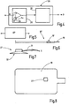
- Weitere Einzelheiten vorteilhafter Ausführungsformen der Erfindung sind Gegenstand von Ansprüchen sowie der Zeichnung und der zugehörigen Beschreibung. Es zeigen:
-
Figur 1 die erfindungsgemäße Einrichtung bei Anwendung an einem Patienten, in schematisierter Darstellung, -
Figur 2 ein Instrument zur Anwendung an dem Patienten, in schematisierter Teilansicht, -
Figur 3 das Gerät zur Speisung des Instruments, in schematisierter Blockdarstellung, -
Figur 4 eine Signalauswerteschaltung des Geräts nachFigur 3 als Blockschaltbild, -
Figur 5 eine Signalverarbeitungseinrichtung, schematisiert, -
Figur 6 ein abgewandeltes Instrument zur Behandlung des Patienten nachFigur 1 , -
Figur 7 einen Sensor zur Anbringung an dem Patienten nachFigur 1 , in Seitenansicht, -
Figur 8 eine Neutralelektrode mit Sensor, in schematisierter Draufsicht, -
Figur 9 die Funktion der Signalauswerteeinrichtung als Diagramm und -
Figur 10 eine abgewandelte Ausführungsform der Einrichtung, in ausschnittsweiser Darstellung. - In
Figur 1 ist eine Operationssituation veranschaulicht, bei der ein Patient 11 auf einem Tisch 12 zur Durchführung eines chirurgischen Eingriffs gelagert ist, der zum Beispiel in einer Körperhöhle 13 des Patienten, zum Beispiel im Urogenitaltrakt, durchzuführen ist. Dazu ist in dem Patienten 11 ein Instrument 14 eingeführt, das mit einem speisenden Gerät 15 verbunden ist. Das Instrument 14 ist beispielsweise eine Sonde 16, die einen steifen oder flexiblen Schaft 17 und an dessen Ende eine Elektrode 18 aufweist. Es kann sich dabei, wie dargestellt, um ein monopolares Instrument handeln. In diesem Fall ist an dem Patienten 11 eine Neutralelektrode 19 angebracht, die beispielsweise durch ein stromverteilendes elektrisch leitfähiges Klebepflaster gebildet ist. - Das Gerät 15 enthält einen Generator 20, der zur Abgabe einer zur Durchführung eines chirurgischen Eingriffs geeigneten HF-Spannung geeignet ist. Diese liegt typischerweise im Bereich von über 100 V vorzugsweise über 200 V mit einer Frequenz von über vorzugsweise deutlich über 100 kHz. Die HF-Spannung kann unmoduliert oder moduliert, beispielsweise pulsbreitenmoduliert sein. Die Elektrode 18 des Instruments 14 ist, wie in
Figur 1 dargestellt, über eine elektrische Leitung L mit einem Ausgang des Generators 20 verbunden. Mit dem anderen Ausgang des Generators 15 ist die Neutralelektrode 19 über eine Leitung M verbunden. - Der Generator 20 kann, wie es
Figur 3 veranschaulicht, aus einem Hochfrequenz-Leistungsoszillator bestehen, dessen Schaltelement 21 einen Schwingkreis 22 erregt, aus dem die Speisespannung für das Instrument 14 transformatorisch oder anderweitig ausgekoppelt wird. Zur Steuerung des Generators 20 dient eine Steuereinrichtung 23, die zum Beispiel auf das Schaltelement 21 einwirkt, um den Schwingkreis 22 dauernd oder impulsweise zu erregen. Zu dem Gerät 15 gehört ein Netzteil oder eine anderweitige Leistungsquelle P zur Versorgung der Steuereinrichtung 23 und des Generators 20. - Die Steuereinrichtung 23 ist mindestens darauf eingerichtet, den Generator 20 zu aktivieren und zu deaktivieren. In der Aktivphase wird das Schaltelement 21 fortwährend geöffnet und geschlossen, während es in der deaktivierten Phase offen (nicht leitend) bleibt.
- Die Steuereinrichtung 23 enthält einen Aktivierungsblock 24, mit einem Aktivierungseingang I, der mit einem Aktivierungsschalter 25 verbunden ist. Dieser ist vorzugsweise manuell betätigbar und beispielsweise als Fußschalter oder als Schalter an dem Instrument 14 ausgebildet. Der Aktivierungsblock 24 weist außerdem einen Sperreingang 0 auf, der mit einem Abschaltblock 26 verbunden ist. Der Abschaltblock weist einen Eingang E auf, an den ein Sensor 27 angeschlossen ist.
- Der Sensor 27 kann als Positionssensor oder wie es bevorzugt wird, insbesondere als Beschleunigungsaufnehmer ausgebildet sein. Der Sensor 27 ist dazu geeignet, seine Bewegung in ein elektrisches Signal umzusetzen. Insbesondere ist der Sensor 27 dazu geeignet, ein der Bewegungsgeschwindigkeit oder der Beschleunigung entsprechendes Signal abzugeben.
- Der Abschaltblock 26 ist in
Figur 4 gesondert veranschaulicht. Er kann beispielsweise einen Komparator 28 aufweisen, der das von dem Sensor 27 kommende Signal mit einem Schwellwert sa vergleicht, das beispielsweise von einem Schwellwertgeber 29 bereitgestellt ist. Das an dem Ausgang des Komparators 28 anstehende Signal kennzeichnet Fälle, in denen das von dem Sensor 27 abgegebene Signal größer ist als der Schwellwert sa. Das Ausgangssignal des Komparators 28 kann einer weiteren Verarbeitung zum Beispiel in einem Block 30 zugeführt werden. Dieser kann je nach Wunsch weitere Funktionen erfüllen. Solche Funktionen können sein: Erzeugen eines Sperrsignals für eine vorgegebene oder für eine einstellbare Zeitspanne, dauerhaftes Erzeugen eines Abschaltsignals bis zu einem Reset oder ähnliches. Ein Resetsignal kann zum Beispiel von dem Aktivierungsschalter 25 oder einem gesonderten Resetschalter gegeben werden. - Optional kann zwischen dem Sensor 27 und dem Eingang E des Abschaltblocks eine Signalverarbeitungseinrichtng, z.B. in Gestalt eines digitalen Signalprozessores DSP angeordnet sein. Dieser kann dazu programmiert sein, das von dem Sensor 27 abgegebene Signal zu filtern oder anderweitig zu verarbeiten. Solche Signalverarbeitung kann Filterblöcke, Verstärkerblöcke, Mustererkennungsblöcke oder dergleichen umfassen. Filterblöcke können Tiefpässe, Hochpässe, Bandpässe sein. Verstärkerblöcke können lineare oder nichtlineare Verstärkerblöcke sein.
- Die insoweit beschriebene Einrichtung arbeitet wie folgt:
Es wird davon ausgegangen, dass ein inFigur 1 nicht weiter dargestellter Behandler das Instrument 14 wie dargestellt, in den Patienten 11 eingeführt und mit dem Aktivierungsschalter 25 aktiviert hat. Zunächst ist der Abschaltblock 26 inaktiv, womit die Steuereinrichtung 23 den Betrieb des Generators 20 freigibt. Der Generator 20 gibt an dem Instrument 14, insbesondere an dessen Elektrode 18, eine HF-Spannung ab, mit der auf Gewebe des Patienten 11 eingewirkt wird. Die Neutralelektrode 19 greift den in den Patienten eingeleiteten Strom ab und leitet diesen zu den Generator 20 zurück. - Gerät der von der Elektrode 18 ausgehende Strom nun in eine Nervenbahn, die zu einer erheblichen Bewegung des Patienten 11 führen könnte, insbesondere in die Nähe des Obturatornervs, kann es zu einer plötzlichen Beinaduktorkontraktion kommen. Sofort mit Beginn einer solchen Bewegung erfasst der Sensor 27 die Bewegung, insbesondere die Geschwindigkeit oder die Beschleunigung der Bewegung. Überschreitet das von dem Sensor 27 abgegebene Signal den von dem Schwellwertgeber 29 festgelegten Schwellwert sa wird ein Abschaltsignal generiert.
- Der Verarbeitungsblock 30 kann, wenn er beispielsweise als Mono-Flop ausgebildet ist, dann für eine festgelegte oder vorgebbare Zeitspanne, beispielsweise für 3 s ein Abschaltsignal erzeugen, das an den Eingang 0 des Aktivierungsblocks 24 gegeben wird. Dieser schaltet somit die Aktivierung des Generators 20 ab. Der Generator 20 wird ausgeschaltet und er gibt zumindest für die von dem Verarbeitungsblock 30 vorgegeben Sperrzeit keine Spannung mehr ab. Damit werden die weitere Reizung des Nerven und somit eine stärkere Beinbewegung wirksam unterbunden. Zwar ist der Behandlungsvorgang zu diesem Zeitpunkt zumindest kurz unterbrochen, jedoch werden wesentliche Verletzungsgefahren durch plötzliche Beinbewegungen des Patienten 11 vermieden. Damit werden auch Operationskomplikationen wirksam vermieden, sie sonst auftreten könnten.
- An der insoweit beschriebenen Erfindung sind zahlreiche Abwandlungen möglich. Eine erste, bei allen vor- und nachstehend beschriebenen Ausführungsformen mögliche Ergänzung ist die Nutzung mehrerer Sensoren 27, die an verschiedenen Stellen einer Extremität oder an verschiedenen Extremitäten insbesondere beiden Beinen des Patienten 11 anbringbar sind. In diesem Fall können die Signale der beiden oder mehreren Sensoren summiert und an den Eingang E des Komparators 28 geführt werden. Es kann auch für jeden Sensor ein eigener Komparator mit einem eigenen Eingang vorgesehen sein, wobei die Ausgangssignale dieser Komaparatoren logisch verknüpft werden können, sodass eine Abschaltung dann erfolgt, wenn wenigstens einer der Komparatoren ein Abschaltsignal liefert (Oder-Verknüpfung).
- Weiter ist es möglich, den Abschaltblock 26 außerhalb des Geräts 15 anzuordnen. In diesem Fall ist der dann noch immer als Teil der Steuereinrichtung des Geräts 15 zu begreifende Abschaltblock 26 außerhalb des Geräts 15, beispielsweise in dem Aktivierungsschalter 25, angeordnet. Der Abschaltblock 26 kann in diesem Fall nach jeder der vorbeschriebenen Ausführungsformen ausgebildet sein und für die Überwachung eines oder mehrerer Sensoren eingerichtet sein. Im Fall einer Abschaltung kann er zum Beispiel das von dem Aktivierungsschalter 24 an den Eingang I der Steuereinrichtung 23 zu gebende Signal unterbrechen oder kurzschließen.
- Der Abschaltblock kann auch in dem Instrument 14 angeordnet sein, insbesondere, wenn der Aktivierungsschalter 25 an dem Instrument angebracht ist. dabei ist es vorteilhaft, wenn der Sensor 27 über eine drahtlose Verbindung mit dem Abschaltblock verbunden ist.
- In einer weiter abgewandelten Ausführungsform kann der Abschaltblock an den Generatorausgang des Generators 20 angeschlossen sein, beispielsweise um die dort anliegende Spannung bei einem Abschaltevent kurzzuschließen. Der Abschaltblock 26 kann alternativ in das Instrument 14 integriert sein.
- Der Sensor 27 ist in
Figur 7 schematisiert gesondert veranschaulicht. Er kann als drahtloser Sensor ausgebildet sein und das von ihm erzeugte, zum Beispiel die Bewegungsgeschwindigkeit oder die Beschleunigung kennzeichnende Signal drahtlos an den Abschaltblock 26 übermitteln. Alternativ kann der Sensor 27 mit einem Kabel 31 versehen sein, das an den Anschluss E des Abschaltblocks 26 anzuschließen ist. - Der Sensor 27 kann zur Befestigung an dem Patienten mit einer Klebefläche 32 versehen sein, die mit Klebe- oder Haftstoff beschichtet ist, um eine Anbringung an der Haut des Patienten zu ermöglichen. Alternativ kann an dem Sensor 27 ein Befestigungsriemen angebracht sein, mit dem der Sensor an dem Patienten festgeschnallt werden kann.
- Es ist weiter möglich, das von dem Sensor 27 abgegebene Signal von Zeit zu Zeit oder fortwährend auf Gültigkeit zu überwachen, um beispielsweise einen an den Patienten nicht korrekt angebrachten oder von diesem abgefallenen Sensor 27 rechtzeitig zu identifizieren. Dazu kann jeder der beschriebenen Ausführungsformen durch einen Überwachungsblock ergänzt werden, der mit dem von dem Sensor abgegebenen Signal verbunden ist. Der Überwachungsblock kann dazu eingerichtet sein, das von dem Sensor 27 abgegebene Signal nur dann als gültiges Signal zu klassifizieren, wenn es über das von dem Sensor 27 ausgehende Grundrauschen hinausgeht und somit allgegenwärtige Mikrobewegungen des Patienten 11 anzeigt. Werden solche Signale nicht mehr empfangen, kann der Abschaltblock 26 die Ungültigkeit des Sensorsignals signalisieren. Es kann vorgesehen sein, dass der der Überwachungsblock in einem solche Fall den Generator 20 still setzt (sperrt).
- Weiter ist es möglich, den Sensor 27 an der Neutralelektrode 19 anzubringen, wie
Figur 8 schematisch veranschaulicht. Solche Lösungen sind insbesondere für monopolare Instrumente nachFigur 2 geeignet. - Es ist jedoch auch der Einsatz bipolarer Instrumente 14' möglich, wie eines in
Figur 6 schematisch veranschaulicht ist. An diesem Instrument 14' ist wiederum die Elektrode 18 und zusätzliche eine Neutralelektrode 19' angebracht. In diesem Fall führen beide Leitungen L und N von dem Instrument 14 zu dem Generator 20. Ansonsten gilt die vorstehende Beschreibung hinsichtlich aller Ausführungen, die nicht speziell die Neutralelektrode 19 nachFigur 8 betreffen, entsprechend. - Eine weitere Abwandlung der Erfindung besteht in der verfeinerten Überwachung des Sensorsignals, beispielsweise, indem dies nicht lediglich mit dem Schwellwert für das Abschalten sa, sondern zusätzlich mit einem niedrigeren Schwellwert sw verglichen wird, um den Chirurgen über das Vorliegen neuromuskulärer Reaktionen warnen zu können.
Figur 9 veranschaulicht dazu die Funktion eines entsprechenden Abschaltblocks. Dieser ist darauf eingerichtet, das Signal S zunächst mit dem Schwellwert sa für das Abschalten zu vergleichen und, wenn dieses erreicht ist, ein Abschaltsignal abzugeben. Ist hingegen der Schwellwert sa nicht erreicht, wird das Signal S mit einem niedrigeren Schwellwert sw verglichen. Wird dieser nicht erreicht, wird nichts unternommen. Überschreitet das Signal S jedoch den Schwellwert sw wird ein Warnsignal ausgegeben. Ein solches Signal kann ein akustisches Signal, ein optisches Signal oder ein taktiles Signal, zum Beispiel die Vibration eines Handgriffs sein. Die soeben beschriebene Überwachung mindestens zweier Schwellwerte kann bei allen vorstehend beschriebenen Ausführungsformen der erfindungsgemäßen Einrichtung Anwendung finden. - Es ist weiter bei allen beschriebenen Ausführungsformen möglich, anstelle des Abschaltens des Generators 20 lediglich eine Leistungsreduzierung desselben oder eine Änderung der Modulationsart vorzunehmen. Allen Ausführungsformen der Erfindung ist jedoch gemeinsam, dass mindestens ein Sensor 27 vorgesehen ist, der eine motorische Reizung des Patienten vorzugsweise an einer Extremität desselben erfasst und dass anhand dieser erfassten Bewegung der Betrieb des Generators 20 und somit die Spannung an der Elektrode 18 des Instruments 14 beeinflusst wird. Die Beeinflussung hat insbesondere die Aufgabe, die der Bewegung des Patienten zugrundeliegende neuromuskuläre Reizung zu mindern oder zu beseitigen.
- Die erfindungsgemäße chirurgische Einrichtung umfasst ein Gerät 19 mit einem Generator 20 sowie ein Instrument 14, das von dem Generator 20 gespeist wird. Außerdem gehört zu der Einrichtung ein Sensor 27, der im Betrieb an dem Patienten insbesondere an einer Extremität desselben angebracht ist, um eine Bewegung des Patienten insbesondere der Extremität zu erfassen. Der Sensor ist mit einer Steuereinrichtung 23 verbunden, die, wenn der Sensor 27 eine einen Schwellwert sa überschreitende Bewegung des Patienten 11 erfasst, den Betrieb des Generators 20 verändert insbesondere den Generator 20 abschaltet.
- Verletzungen des Patienten 11, die durch unwillkürliche Zuckungen während des Operationsprozesses entstehen könnten, werden somit vermieden.
-
- 11 Patient
- 12 Tisch
- 13 Hohlorgan
- 14, 14' Instrument
- 15 Gerät
- 16 Sonde
- 17 Schaft
- 18 Elektrode
- 19, 19' Neutralelektrode
- 20 Generator
- L Leitung
- N Leitung
- 21 Schaltelement
- 22 Schwingkreis
- 23 Steuereinrichtung
- 24 Aktivierungsblock
- I Aktivierungseingang
- 25 Aktivierungsschalter
- 0 Sperreingang
- 26 Abschaltblock /Signalauswerteeinrichtung
- E Eingang
- S Sensorsignal
- 27 Sensor
- 28 Komparator
- sa erster Schwellwert (für das Abschalten)
- sw zweiter Schwellwert (für die Abgabe einer Warnung)
- 29 Schwellwertgeber
- 30 Verarbeitungsblock
- 31 Kabel
- 32 Befestigungseinrichtung (Klebefläche)
- 33 Abschnitt der Signalauswerteeinrichtung
Claims (15)
- Chirurgische Einrichtung zur Durchführung eines elektrochirurgischen Eingriffs an einem Patienten,
mit einem Gerät (15), das einen Generator (20) zur Erzeugung einer Behandlungsspannung und eine Steuereinrichtung (23) zur Steuerung des Generators (20) aufweist,
mit einem Instrument (14), das wenigstens eine Elektrode (18) aufweist und das an den Generator (20) angeschlossen ist,
mit einem Sensor (27), der zur Anbringung an dem Patienten (11) und zur Erfassung einer Bewegung des Patienten eingerichtet und der mit der Steuereinrichtung (23) verbunden ist. - Einrichtung nach Anspruch 1, dadurch gekennzeichnet, dass die Steuereinrichtung (23) eine Signalauswerteeinrichtung (26) enthält, die dazu eingerichtet ist, den Generator (20) von dem Sensor (27) gesteuert abzuschalten.
- Einrichtung nach einem der vorstehenden Ansprüche, dadurch gekennzeichnet, dass der Sensor (27) ein Bewegungssensor ist.
- Einrichtung nach einem der vorstehenden Ansprüche, dadurch gekennzeichnet, dass der Sensor (27) ein Beschleunigungssensor ist.
- Einrichtung nach einem der vorstehenden Ansprüche, dadurch gekennzeichnet, dass der Sensor (27) eine Befestigungseinrichtung (32) aufweist, mittels derer er an einer Extremität, insbesondere einem Fuß oder einem Bein des Patienten (11) befestigbar ist.
- Einrichtung nach Anspruch 5, dadurch gekennzeichnet, dass die Befestigungseinrichtung (32) eine Klebefläche oder ein Befestigungsband ist.
- Einrichtung nach einem der vorstehenden Ansprüche, dadurch gekennzeichnet, dass die Steuereinrichtung (23) eine Signalauswerteeinrichtung (26) aufweist, die dazu eingerichtet ist, das von dem Sensor (27) gelieferte Signal (S) mit einem Schwellwert (sa) zu vergleichen und ein Abschaltsignal zu erzeugen, sofern der Schwellwert (sa) überschritten ist.
- Einrichtung nach Anspruch 7, dadurch gekennzeichnet, dass die Signalauswerteeinrichtung (26) dazu eingerichtet ist, das Abschaltsignal für eine definierte Zeitspanne zu erzeugen.
- Einrichtung nach Anspruch 8, dadurch gekennzeichnet, dass die Zeitspanne einstellbar ist.
- Einrichtung nach einem der vorstehenden Ansprüche, dadurch gekennzeichnet, dass die Signalauswerteeinrichtung (26) dazu eingerichtet ist, das Signal (S) wenigstens hinsichtlich zweier Schwellwerte (sa, sw) zu überwachen, um bei Überschreitung eines ersten Schwellwerts (sw) ein Warnsignal und bei Überschreitung eines zweiten Schwellwerts (sa) ein Abschaltsignal zu erzeugen.
- Einrichtung nach einem der vorstehenden Ansprüche, dadurch gekennzeichnet, dass der Generator (20) mit einer an dem Instrument (14) vorgesehenen Neutralelektrode (19) verbunden ist.
- Einrichtung nach einem der vorstehenden Ansprüche, dadurch gekennzeichnet, dass der Generator (20) mit einer Neutralelektrode (19) verbunden ist, die an dem Patienten (11) anbringbar ist.
- Einrichtung nach Anspruch 12, dadurch gekennzeichnet, dass die Neutralelektrode (19) den Sensor (27) enthält.
- Einrichtung nach einem der vorstehenden Ansprüche, dadurch gekennzeichnet, dass die Steuereinrichtung (23) zumindest einen außerhalb des Geräts (15) angeordneten Abschnitt (33) aufweist.
- Einrichtung nach einem der Ansprüche 2, 7, 8, 9 oder 10, dadurch gekennzeichnet, dass der außerhalb des Geräts angeordnete Abschnitt (33) die Signalauswerteeinrichtung (26) enthält.
Priority Applications (8)
| Application Number | Priority Date | Filing Date | Title |
|---|---|---|---|
| PL19187086.4T PL3766446T3 (pl) | 2019-07-18 | 2019-07-18 | Urządzenie do wykonywania zabiegu elektrochirurgicznego u pacjenta |
| EP19187086.4A EP3766446B1 (de) | 2019-07-18 | 2019-07-18 | Einrichtung zur durchführung eines elektrochirurgischen eingriffs an einem patienten |
| RU2020122551A RU2822634C2 (ru) | 2019-07-18 | 2020-07-08 | Устройство для осуществления электрохирургического вмешательства на пациенте |
| US16/923,791 US12042213B2 (en) | 2019-07-18 | 2020-07-08 | Device for carrying out an electrosurgical intervention on a patient |
| JP2020118393A JP7522597B2 (ja) | 2019-07-18 | 2020-07-09 | 患者に電気外科的処置を実施するための装置 |
| KR1020200086131A KR20210010824A (ko) | 2019-07-18 | 2020-07-13 | 환자에게 전기수술적 개입을 수행하기 위한 장치 |
| BR102020014310-7A BR102020014310A2 (pt) | 2019-07-18 | 2020-07-14 | Dispositivo para realizar uma intervenção eletrocirúrgica em um paciente |
| CN202010691878.XA CN112315575A (zh) | 2019-07-18 | 2020-07-17 | 用于在患者上进行电外科手术介入的装置 |
Applications Claiming Priority (1)
| Application Number | Priority Date | Filing Date | Title |
|---|---|---|---|
| EP19187086.4A EP3766446B1 (de) | 2019-07-18 | 2019-07-18 | Einrichtung zur durchführung eines elektrochirurgischen eingriffs an einem patienten |
Publications (3)
| Publication Number | Publication Date |
|---|---|
| EP3766446A1 true EP3766446A1 (de) | 2021-01-20 |
| EP3766446B1 EP3766446B1 (de) | 2024-02-14 |
| EP3766446C0 EP3766446C0 (de) | 2024-02-14 |
Family
ID=67438033
Family Applications (1)
| Application Number | Title | Priority Date | Filing Date |
|---|---|---|---|
| EP19187086.4A Active EP3766446B1 (de) | 2019-07-18 | 2019-07-18 | Einrichtung zur durchführung eines elektrochirurgischen eingriffs an einem patienten |
Country Status (7)
| Country | Link |
|---|---|
| US (1) | US12042213B2 (de) |
| EP (1) | EP3766446B1 (de) |
| JP (1) | JP7522597B2 (de) |
| KR (1) | KR20210010824A (de) |
| CN (1) | CN112315575A (de) |
| BR (1) | BR102020014310A2 (de) |
| PL (1) | PL3766446T3 (de) |
Families Citing this family (1)
| Publication number | Priority date | Publication date | Assignee | Title |
|---|---|---|---|---|
| EP4732799A1 (de) * | 2024-10-28 | 2026-04-29 | Olympus Winter & Ibe Gmbh | Bildgebungsunterstützung einer transurethralen prostataresektion und turp-system |
Citations (3)
| Publication number | Priority date | Publication date | Assignee | Title |
|---|---|---|---|---|
| US4231372A (en) * | 1974-11-04 | 1980-11-04 | Valleylab, Inc. | Safety monitoring circuit for electrosurgical unit |
| DE3238123A1 (de) * | 1982-10-14 | 1984-04-19 | Erbe Elektromedizin GmbH, 7400 Tübingen | Hochfrequenz-chirurgiegeraet |
| WO2019068105A1 (en) * | 2017-10-01 | 2019-04-04 | Neuromuscular Surgical Llc | DEVICES AND METHODS FOR SURGICAL SAFETY |
Family Cites Families (13)
| Publication number | Priority date | Publication date | Assignee | Title |
|---|---|---|---|---|
| JPS57185848A (en) * | 1981-05-12 | 1982-11-16 | Olympus Optical Co | High frequency output apparatus for electric knife |
| DE3228136C2 (de) * | 1982-07-28 | 1985-05-30 | Erbe Elektromedizin GmbH, 7400 Tübingen | Hochfrequenz-Chirurgiegerät |
| RU2204351C2 (ru) | 2001-06-25 | 2003-05-20 | Белик Дмитрий Васильевич | Импедансный электрохирургический аппарат |
| DE102004054575A1 (de) * | 2004-11-11 | 2006-05-24 | Erbe Elektromedizin Gmbh | Regelung für ein HF-Chirurgiegerät |
| US8503193B2 (en) * | 2010-08-26 | 2013-08-06 | Astec International Limited | Open loop DC to DC converters with enable/disable circuits |
| JP6309447B2 (ja) | 2011-05-31 | 2018-04-11 | インテュイティブ サージカル オペレーションズ, インコーポレイテッド | ロボットによる手術用器具のエンドエフェクタの積極的な制御 |
| ES2533717T3 (es) * | 2011-11-03 | 2015-04-14 | Inomed Medizintechnik Gmbh | Disposición de control para la supervisión intraoperativa de la función nerviosa en la zona de la pelvis |
| US9393071B1 (en) | 2012-12-18 | 2016-07-19 | Abl Technologies, Llc | Methods and systems of temperature based alarms and/or automatic interrupt (shutoff) during a cardiac ablation procedure |
| US9693816B2 (en) | 2012-01-30 | 2017-07-04 | Covidien Lp | Electrosurgical apparatus with integrated energy sensing at tissue site |
| US20140303660A1 (en) | 2013-04-04 | 2014-10-09 | Elwha Llc | Active tremor control in surgical instruments |
| US9918730B2 (en) * | 2014-04-08 | 2018-03-20 | Ethicon Llc | Methods and devices for controlling motorized surgical devices |
| EP3435864A4 (de) * | 2016-03-31 | 2019-09-18 | Zoll Medical Corporation | System und verfahren zur verfolgung von patientenbewegung |
| US11844579B2 (en) | 2017-12-28 | 2023-12-19 | Cilag Gmbh International | Adjustments based on airborne particle properties |
-
2019
- 2019-07-18 EP EP19187086.4A patent/EP3766446B1/de active Active
- 2019-07-18 PL PL19187086.4T patent/PL3766446T3/pl unknown
-
2020
- 2020-07-08 US US16/923,791 patent/US12042213B2/en active Active
- 2020-07-09 JP JP2020118393A patent/JP7522597B2/ja active Active
- 2020-07-13 KR KR1020200086131A patent/KR20210010824A/ko active Pending
- 2020-07-14 BR BR102020014310-7A patent/BR102020014310A2/pt not_active Application Discontinuation
- 2020-07-17 CN CN202010691878.XA patent/CN112315575A/zh active Pending
Patent Citations (3)
| Publication number | Priority date | Publication date | Assignee | Title |
|---|---|---|---|---|
| US4231372A (en) * | 1974-11-04 | 1980-11-04 | Valleylab, Inc. | Safety monitoring circuit for electrosurgical unit |
| DE3238123A1 (de) * | 1982-10-14 | 1984-04-19 | Erbe Elektromedizin GmbH, 7400 Tübingen | Hochfrequenz-chirurgiegeraet |
| WO2019068105A1 (en) * | 2017-10-01 | 2019-04-04 | Neuromuscular Surgical Llc | DEVICES AND METHODS FOR SURGICAL SAFETY |
Non-Patent Citations (21)
Also Published As
| Publication number | Publication date |
|---|---|
| JP7522597B2 (ja) | 2024-07-25 |
| PL3766446T3 (pl) | 2024-05-13 |
| RU2020122551A (ru) | 2022-01-10 |
| BR102020014310A2 (pt) | 2021-04-13 |
| KR20210010824A (ko) | 2021-01-28 |
| US20210015547A1 (en) | 2021-01-21 |
| CN112315575A (zh) | 2021-02-05 |
| US12042213B2 (en) | 2024-07-23 |
| EP3766446B1 (de) | 2024-02-14 |
| JP2021016784A (ja) | 2021-02-15 |
| EP3766446C0 (de) | 2024-02-14 |
Similar Documents
| Publication | Publication Date | Title |
|---|---|---|
| EP0316469B1 (de) | Hochfrequenz-Chirugiegerät zum Schneiden und/oder Koagulieren biologischer Gewebe | |
| DE60026191T2 (de) | Automatische Aktivierung des bipolaren Ausgangssignals eines elektrochirurgischen Generators | |
| EP1499253B1 (de) | Hochfrequenz-chirurgiegenerator | |
| DE69805335T2 (de) | Elektrochirurgischer radiofrequenz-erzeuger mit stromregelung | |
| DE3510586C2 (de) | ||
| EP0253012B1 (de) | Hochfrequenz-Chirurgiegerät für die thermische Koagulation biologischer Gewebe | |
| DE69227130T2 (de) | Elektrochirurgisches und chirurgisches ultraschallsystem | |
| EP0341446B1 (de) | Hochfrequenzgenerator zum Gewebeschneiden und Koagulieren in der Hochfrequenzchirurgie | |
| EP0219568B1 (de) | Hochfrequenz-Chirurgiegerät | |
| EP0598780A1 (de) | Hochfrequenzchirurgiegenerator zum schneiden von geweben | |
| DE2901153A1 (de) | Elektrochirurgischer generator | |
| EP0812576A1 (de) | Elektrochirurgischer Hochfrequenz-Generator | |
| DE102007034271A1 (de) | Hochfrequenzchirurgiegerät und Verfahren zu dessen Betrieb | |
| DE1489702A1 (de) | Vorrichtung und Schaltungsanordnung zum Anaesthesieren | |
| DE3426141C2 (de) | Elektrolysegerät | |
| EP3766446B1 (de) | Einrichtung zur durchführung eines elektrochirurgischen eingriffs an einem patienten | |
| DE19542419B4 (de) | Hochfrequenzgenerator für die Hochfrequenzchirurgie mit Gewebedifferenzierung | |
| EP0005713B1 (de) | Magnetfeldbehandlungsgerät | |
| DE102004056636A1 (de) | Hochfrequenzchirurgie-Gerät und Verfahren zu dessen Betrieb | |
| EP0978259B1 (de) | Hochfrequenzchirurgiegenerator mit einer einstellbaren Ausgangsleistung | |
| WO2018069533A1 (de) | Hochfrequenzgenerator zum anschliessen eines instruments für die behandlung von körpergewebe | |
| RU2822634C2 (ru) | Устройство для осуществления электрохирургического вмешательства на пациенте | |
| DE4126609A1 (de) | Hochfrequenzchirurgiegenerator zum geregelten koagulierenden schneiden | |
| DE3530456C2 (de) | ||
| DE4135185A1 (de) | Hochfrequenzchirurgiegenerator zur koagulation von geweben |
Legal Events
| Date | Code | Title | Description |
|---|---|---|---|
| PUAI | Public reference made under article 153(3) epc to a published international application that has entered the european phase |
Free format text: ORIGINAL CODE: 0009012 |
|
| STAA | Information on the status of an ep patent application or granted ep patent |
Free format text: STATUS: THE APPLICATION HAS BEEN PUBLISHED |
|
| AK | Designated contracting states |
Kind code of ref document: A1 Designated state(s): AL AT BE BG CH CY CZ DE DK EE ES FI FR GB GR HR HU IE IS IT LI LT LU LV MC MK MT NL NO PL PT RO RS SE SI SK SM TR |
|
| AX | Request for extension of the european patent |
Extension state: BA ME |
|
| STAA | Information on the status of an ep patent application or granted ep patent |
Free format text: STATUS: REQUEST FOR EXAMINATION WAS MADE |
|
| 17P | Request for examination filed |
Effective date: 20210511 |
|
| RBV | Designated contracting states (corrected) |
Designated state(s): AL AT BE BG CH CY CZ DE DK EE ES FI FR GB GR HR HU IE IS IT LI LT LU LV MC MK MT NL NO PL PT RO RS SE SI SK SM TR |
|
| GRAP | Despatch of communication of intention to grant a patent |
Free format text: ORIGINAL CODE: EPIDOSNIGR1 |
|
| STAA | Information on the status of an ep patent application or granted ep patent |
Free format text: STATUS: GRANT OF PATENT IS INTENDED |
|
| RIC1 | Information provided on ipc code assigned before grant |
Ipc: A61B 17/00 20060101ALN20230906BHEP Ipc: A61B 5/00 20060101ALN20230906BHEP Ipc: A61B 5/11 20060101ALN20230906BHEP Ipc: A61B 18/00 20060101ALN20230906BHEP Ipc: A61B 18/12 20060101AFI20230906BHEP |
|
| RIC1 | Information provided on ipc code assigned before grant |
Ipc: A61B 17/00 20060101ALN20230918BHEP Ipc: A61B 5/00 20060101ALN20230918BHEP Ipc: A61B 5/11 20060101ALN20230918BHEP Ipc: A61B 18/00 20060101ALN20230918BHEP Ipc: A61B 18/12 20060101AFI20230918BHEP |
|
| INTG | Intention to grant announced |
Effective date: 20231011 |
|
| GRAS | Grant fee paid |
Free format text: ORIGINAL CODE: EPIDOSNIGR3 |
|
| GRAA | (expected) grant |
Free format text: ORIGINAL CODE: 0009210 |
|
| STAA | Information on the status of an ep patent application or granted ep patent |
Free format text: STATUS: THE PATENT HAS BEEN GRANTED |
|
| AK | Designated contracting states |
Kind code of ref document: B1 Designated state(s): AL AT BE BG CH CY CZ DE DK EE ES FI FR GB GR HR HU IE IS IT LI LT LU LV MC MK MT NL NO PL PT RO RS SE SI SK SM TR |
|
| REG | Reference to a national code |
Ref country code: GB Ref legal event code: FG4D Free format text: NOT ENGLISH |
|
| REG | Reference to a national code |
Ref country code: CH Ref legal event code: EP |
|
| REG | Reference to a national code |
Ref country code: DE Ref legal event code: R096 Ref document number: 502019010569 Country of ref document: DE |
|
| REG | Reference to a national code |
Ref country code: IE Ref legal event code: FG4D Free format text: LANGUAGE OF EP DOCUMENT: GERMAN |
|
| U01 | Request for unitary effect filed |
Effective date: 20240215 |
|
| U07 | Unitary effect registered |
Designated state(s): AT BE BG DE DK EE FI FR IT LT LU LV MT NL PT SE SI Effective date: 20240226 |
|
| PG25 | Lapsed in a contracting state [announced via postgrant information from national office to epo] |
Ref country code: IS Free format text: LAPSE BECAUSE OF FAILURE TO SUBMIT A TRANSLATION OF THE DESCRIPTION OR TO PAY THE FEE WITHIN THE PRESCRIBED TIME-LIMIT Effective date: 20240614 |
|
| PG25 | Lapsed in a contracting state [announced via postgrant information from national office to epo] |
Ref country code: GR Free format text: LAPSE BECAUSE OF FAILURE TO SUBMIT A TRANSLATION OF THE DESCRIPTION OR TO PAY THE FEE WITHIN THE PRESCRIBED TIME-LIMIT Effective date: 20240515 |
|
| PG25 | Lapsed in a contracting state [announced via postgrant information from national office to epo] |
Ref country code: HR Free format text: LAPSE BECAUSE OF FAILURE TO SUBMIT A TRANSLATION OF THE DESCRIPTION OR TO PAY THE FEE WITHIN THE PRESCRIBED TIME-LIMIT Effective date: 20240214 Ref country code: RS Free format text: LAPSE BECAUSE OF FAILURE TO SUBMIT A TRANSLATION OF THE DESCRIPTION OR TO PAY THE FEE WITHIN THE PRESCRIBED TIME-LIMIT Effective date: 20240514 |
|
| PG25 | Lapsed in a contracting state [announced via postgrant information from national office to epo] |
Ref country code: ES Free format text: LAPSE BECAUSE OF FAILURE TO SUBMIT A TRANSLATION OF THE DESCRIPTION OR TO PAY THE FEE WITHIN THE PRESCRIBED TIME-LIMIT Effective date: 20240214 |
|
| PG25 | Lapsed in a contracting state [announced via postgrant information from national office to epo] |
Ref country code: RS Free format text: LAPSE BECAUSE OF FAILURE TO SUBMIT A TRANSLATION OF THE DESCRIPTION OR TO PAY THE FEE WITHIN THE PRESCRIBED TIME-LIMIT Effective date: 20240514 Ref country code: NO Free format text: LAPSE BECAUSE OF FAILURE TO SUBMIT A TRANSLATION OF THE DESCRIPTION OR TO PAY THE FEE WITHIN THE PRESCRIBED TIME-LIMIT Effective date: 20240514 Ref country code: IS Free format text: LAPSE BECAUSE OF FAILURE TO SUBMIT A TRANSLATION OF THE DESCRIPTION OR TO PAY THE FEE WITHIN THE PRESCRIBED TIME-LIMIT Effective date: 20240614 Ref country code: HR Free format text: LAPSE BECAUSE OF FAILURE TO SUBMIT A TRANSLATION OF THE DESCRIPTION OR TO PAY THE FEE WITHIN THE PRESCRIBED TIME-LIMIT Effective date: 20240214 Ref country code: GR Free format text: LAPSE BECAUSE OF FAILURE TO SUBMIT A TRANSLATION OF THE DESCRIPTION OR TO PAY THE FEE WITHIN THE PRESCRIBED TIME-LIMIT Effective date: 20240515 Ref country code: ES Free format text: LAPSE BECAUSE OF FAILURE TO SUBMIT A TRANSLATION OF THE DESCRIPTION OR TO PAY THE FEE WITHIN THE PRESCRIBED TIME-LIMIT Effective date: 20240214 |
|
| PGFP | Annual fee paid to national office [announced via postgrant information from national office to epo] |
Ref country code: PL Payment date: 20240625 Year of fee payment: 6 |
|
| U20 | Renewal fee for the european patent with unitary effect paid |
Year of fee payment: 6 Effective date: 20240725 |
|
| PG25 | Lapsed in a contracting state [announced via postgrant information from national office to epo] |
Ref country code: SM Free format text: LAPSE BECAUSE OF FAILURE TO SUBMIT A TRANSLATION OF THE DESCRIPTION OR TO PAY THE FEE WITHIN THE PRESCRIBED TIME-LIMIT Effective date: 20240214 |
|
| PGFP | Annual fee paid to national office [announced via postgrant information from national office to epo] |
Ref country code: GB Payment date: 20240724 Year of fee payment: 6 |
|
| PG25 | Lapsed in a contracting state [announced via postgrant information from national office to epo] |
Ref country code: CZ Free format text: LAPSE BECAUSE OF FAILURE TO SUBMIT A TRANSLATION OF THE DESCRIPTION OR TO PAY THE FEE WITHIN THE PRESCRIBED TIME-LIMIT Effective date: 20240214 |
|
| PG25 | Lapsed in a contracting state [announced via postgrant information from national office to epo] |
Ref country code: SK Free format text: LAPSE BECAUSE OF FAILURE TO SUBMIT A TRANSLATION OF THE DESCRIPTION OR TO PAY THE FEE WITHIN THE PRESCRIBED TIME-LIMIT Effective date: 20240214 |
|
| PG25 | Lapsed in a contracting state [announced via postgrant information from national office to epo] |
Ref country code: SM Free format text: LAPSE BECAUSE OF FAILURE TO SUBMIT A TRANSLATION OF THE DESCRIPTION OR TO PAY THE FEE WITHIN THE PRESCRIBED TIME-LIMIT Effective date: 20240214 Ref country code: SK Free format text: LAPSE BECAUSE OF FAILURE TO SUBMIT A TRANSLATION OF THE DESCRIPTION OR TO PAY THE FEE WITHIN THE PRESCRIBED TIME-LIMIT Effective date: 20240214 Ref country code: RO Free format text: LAPSE BECAUSE OF FAILURE TO SUBMIT A TRANSLATION OF THE DESCRIPTION OR TO PAY THE FEE WITHIN THE PRESCRIBED TIME-LIMIT Effective date: 20240214 Ref country code: CZ Free format text: LAPSE BECAUSE OF FAILURE TO SUBMIT A TRANSLATION OF THE DESCRIPTION OR TO PAY THE FEE WITHIN THE PRESCRIBED TIME-LIMIT Effective date: 20240214 |
|
| REG | Reference to a national code |
Ref country code: DE Ref legal event code: R097 Ref document number: 502019010569 Country of ref document: DE |
|
| PLBE | No opposition filed within time limit |
Free format text: ORIGINAL CODE: 0009261 |
|
| STAA | Information on the status of an ep patent application or granted ep patent |
Free format text: STATUS: NO OPPOSITION FILED WITHIN TIME LIMIT |
|
| 26N | No opposition filed |
Effective date: 20241115 |
|
| PG25 | Lapsed in a contracting state [announced via postgrant information from national office to epo] |
Ref country code: MC Free format text: LAPSE BECAUSE OF FAILURE TO SUBMIT A TRANSLATION OF THE DESCRIPTION OR TO PAY THE FEE WITHIN THE PRESCRIBED TIME-LIMIT Effective date: 20240214 |
|
| REG | Reference to a national code |
Ref country code: CH Ref legal event code: PL |
|
| PG25 | Lapsed in a contracting state [announced via postgrant information from national office to epo] |
Ref country code: CH Free format text: LAPSE BECAUSE OF NON-PAYMENT OF DUE FEES Effective date: 20240731 |
|
| U1N | Appointed representative for the unitary patent procedure changed after the registration of the unitary effect |
Representative=s name: RUEGER ABEL PATENTANWAELTE PARTGMBB; DE |
|
| PG25 | Lapsed in a contracting state [announced via postgrant information from national office to epo] |
Ref country code: IE Free format text: LAPSE BECAUSE OF NON-PAYMENT OF DUE FEES Effective date: 20240718 |
|
| PG25 | Lapsed in a contracting state [announced via postgrant information from national office to epo] |
Ref country code: CY Free format text: LAPSE BECAUSE OF FAILURE TO SUBMIT A TRANSLATION OF THE DESCRIPTION OR TO PAY THE FEE WITHIN THE PRESCRIBED TIME-LIMIT; INVALID AB INITIO Effective date: 20190718 |
|
| PG25 | Lapsed in a contracting state [announced via postgrant information from national office to epo] |
Ref country code: HU Free format text: LAPSE BECAUSE OF FAILURE TO SUBMIT A TRANSLATION OF THE DESCRIPTION OR TO PAY THE FEE WITHIN THE PRESCRIBED TIME-LIMIT; INVALID AB INITIO Effective date: 20190718 |
|
| U90 | Renewal fees not paid: noting of loss of rights |
Free format text: RENEWAL FEE NOT PAID FOR YEAR 07 Effective date: 20260218 |
|
| GBPC | Gb: european patent ceased through non-payment of renewal fee |
Effective date: 20250718 |
|
| PG25 | Lapsed in a contracting state [announced via postgrant information from national office to epo] |
Ref country code: GB Free format text: LAPSE BECAUSE OF NON-PAYMENT OF DUE FEES Effective date: 20250718 |