EP3766321B1 - Machine agricole et programme de calcul de degré d'écart - Google Patents
Machine agricole et programme de calcul de degré d'écart Download PDFInfo
- Publication number
- EP3766321B1 EP3766321B1 EP19768156.2A EP19768156A EP3766321B1 EP 3766321 B1 EP3766321 B1 EP 3766321B1 EP 19768156 A EP19768156 A EP 19768156A EP 3766321 B1 EP3766321 B1 EP 3766321B1
- Authority
- EP
- European Patent Office
- Prior art keywords
- work vehicle
- target
- rectangle
- crop rows
- crop
- Prior art date
- Legal status (The legal status is an assumption and is not a legal conclusion. Google has not performed a legal analysis and makes no representation as to the accuracy of the status listed.)
- Active
Links
- 238000012937 correction Methods 0.000 claims description 15
- 238000013459 approach Methods 0.000 claims description 14
- 238000000034 method Methods 0.000 description 37
- 230000008569 process Effects 0.000 description 23
- 239000007788 liquid Substances 0.000 description 20
- 239000000126 substance Substances 0.000 description 19
- 230000007246 mechanism Effects 0.000 description 13
- 238000001514 detection method Methods 0.000 description 11
- 238000005452 bending Methods 0.000 description 10
- 230000008859 change Effects 0.000 description 10
- 238000010586 diagram Methods 0.000 description 10
- 230000005484 gravity Effects 0.000 description 9
- 238000005507 spraying Methods 0.000 description 5
- 230000008878 coupling Effects 0.000 description 2
- 238000010168 coupling process Methods 0.000 description 2
- 238000005859 coupling reaction Methods 0.000 description 2
- 230000000694 effects Effects 0.000 description 2
- 239000000446 fuel Substances 0.000 description 2
- 238000003384 imaging method Methods 0.000 description 2
- 239000002420 orchard Substances 0.000 description 2
- 235000013399 edible fruits Nutrition 0.000 description 1
- 230000006870 function Effects 0.000 description 1
- 238000002347 injection Methods 0.000 description 1
- 239000007924 injection Substances 0.000 description 1
- 238000005259 measurement Methods 0.000 description 1
- 239000000575 pesticide Substances 0.000 description 1
- 238000012545 processing Methods 0.000 description 1
- 239000002689 soil Substances 0.000 description 1
- 239000007921 spray Substances 0.000 description 1
- XLYOFNOQVPJJNP-UHFFFAOYSA-N water Substances O XLYOFNOQVPJJNP-UHFFFAOYSA-N 0.000 description 1
Images


Classifications
-
- G—PHYSICS
- G01—MEASURING; TESTING
- G01C—MEASURING DISTANCES, LEVELS OR BEARINGS; SURVEYING; NAVIGATION; GYROSCOPIC INSTRUMENTS; PHOTOGRAMMETRY OR VIDEOGRAMMETRY
- G01C21/00—Navigation; Navigational instruments not provided for in groups G01C1/00 - G01C19/00
- G01C21/005—Navigation; Navigational instruments not provided for in groups G01C1/00 - G01C19/00 with correlation of navigation data from several sources, e.g. map or contour matching
-
- A—HUMAN NECESSITIES
- A01—AGRICULTURE; FORESTRY; ANIMAL HUSBANDRY; HUNTING; TRAPPING; FISHING
- A01B—SOIL WORKING IN AGRICULTURE OR FORESTRY; PARTS, DETAILS, OR ACCESSORIES OF AGRICULTURAL MACHINES OR IMPLEMENTS, IN GENERAL
- A01B69/00—Steering of agricultural machines or implements; Guiding agricultural machines or implements on a desired track
- A01B69/001—Steering by means of optical assistance, e.g. television cameras
-
- A—HUMAN NECESSITIES
- A01—AGRICULTURE; FORESTRY; ANIMAL HUSBANDRY; HUNTING; TRAPPING; FISHING
- A01B—SOIL WORKING IN AGRICULTURE OR FORESTRY; PARTS, DETAILS, OR ACCESSORIES OF AGRICULTURAL MACHINES OR IMPLEMENTS, IN GENERAL
- A01B69/00—Steering of agricultural machines or implements; Guiding agricultural machines or implements on a desired track
- A01B69/007—Steering or guiding of agricultural vehicles, e.g. steering of the tractor to keep the plough in the furrow
- A01B69/008—Steering or guiding of agricultural vehicles, e.g. steering of the tractor to keep the plough in the furrow automatic
-
- G—PHYSICS
- G01—MEASURING; TESTING
- G01C—MEASURING DISTANCES, LEVELS OR BEARINGS; SURVEYING; NAVIGATION; GYROSCOPIC INSTRUMENTS; PHOTOGRAMMETRY OR VIDEOGRAMMETRY
- G01C21/00—Navigation; Navigational instruments not provided for in groups G01C1/00 - G01C19/00
- G01C21/20—Instruments for performing navigational calculations
-
- G—PHYSICS
- G01—MEASURING; TESTING
- G01S—RADIO DIRECTION-FINDING; RADIO NAVIGATION; DETERMINING DISTANCE OR VELOCITY BY USE OF RADIO WAVES; LOCATING OR PRESENCE-DETECTING BY USE OF THE REFLECTION OR RERADIATION OF RADIO WAVES; ANALOGOUS ARRANGEMENTS USING OTHER WAVES
- G01S17/00—Systems using the reflection or reradiation of electromagnetic waves other than radio waves, e.g. lidar systems
- G01S17/88—Lidar systems specially adapted for specific applications
- G01S17/89—Lidar systems specially adapted for specific applications for mapping or imaging
-
- G—PHYSICS
- G01—MEASURING; TESTING
- G01S—RADIO DIRECTION-FINDING; RADIO NAVIGATION; DETERMINING DISTANCE OR VELOCITY BY USE OF RADIO WAVES; LOCATING OR PRESENCE-DETECTING BY USE OF THE REFLECTION OR RERADIATION OF RADIO WAVES; ANALOGOUS ARRANGEMENTS USING OTHER WAVES
- G01S7/00—Details of systems according to groups G01S13/00, G01S15/00, G01S17/00
- G01S7/48—Details of systems according to groups G01S13/00, G01S15/00, G01S17/00 of systems according to group G01S17/00
- G01S7/4802—Details of systems according to groups G01S13/00, G01S15/00, G01S17/00 of systems according to group G01S17/00 using analysis of echo signal for target characterisation; Target signature; Target cross-section
Definitions
- This invention relates to a work vehicle and a deviation amount calculation program.
- Patent Literature 1 discloses a work machine that travels along a furrow.
- an automatic travel control of the work machine is performed on the basis of the angle of the work machine to a ridge and a position deviation amount of the work machine from the center of the ridge.
- Patent Literature 2 discloses a harvester that performs an automatic travel control when the traveling direction of the machine approaches one side of the right and left crop rows.
- Patent Literature 1 Disclosed in Patent Literature 1 is a technique directed to a field where there are ridges the edges of which can be detected relatively easily. For example, in the case of an orchard without ridges, a trunk is hidden by the leaves and branches of a crop, and thus it may not be possible to accurately detect a crop row. Therefore, it is difficult to apply the travel control such as that in Patent Literature 1 to a field without ridges.
- Patent Literature 2 an image acquired by an imaging means is rotated, an amount of deviation of a work machine from the center position of a ridge is calculated on the basis of this rotated image, and an angle in the traveling direction of the work machine with respect to the ridge is calculated. This is a process on condition that ridges extend straight along the traveling direction of the work machine. Therefore, in Patent Literature 2, when the ridges do not extend straight, it is difficult to identify the position and angle (direction) of the work machine.
- Patent Literature 2 Even in Patent Literature 2, the position and direction of the harvester when each crop row does not extend straight are not considered.
- Documents JP H01 206904 A and US 2010/104194 A1 disclose a work vehicle configured to travel in a field where a plurality of crop rows are planted.
- the work vehicle comprises a distance sensor configured to acquire information on a distance from the work vehicle to each of a plurality of objects present in the field.
- a work vehicle is a work vehicle that is configured to travel in a field where a plurality of crop rows are planted, and that includes a distance sensor configured to acquire information on a distance from the work vehicle to each of a plurality of objects present in the field, a rectangle identification unit configured to estimate the plurality of crop rows on a basis of the distance information and identify a rectangle whose opposite sides are adjacent crop rows of the estimated crop rows, a target setting unit configured to set a target travel route of the work vehicle between the adjacent crop rows on a basis of the rectangle, and a position deviation calculation unit configured to estimate a current position of the work vehicle between the adjacent crop rows on a basis of the rectangle, and calculate a deviation amount of the current position from the target travel route.
- a rectangle whose opposite sides are adjacent crop rows is identified, and the target travel route is set on the basis of the identified rectangle, and at the same time the current position of the work vehicle is estimated. Therefore, for example, when the slopes of adjacent crop rows change in the middle, such as when the adjacent crop rows bend in the middle, a rectangle according to a slope near the work vehicle in the adjacent crop rows is identified. This makes it possible to set a target travel route between adjacent crop rows corresponding to changes in the slopes of these crop rows, and to estimate the position of the work vehicle between the adjacent crop rows. In other words, with this configuration, it is possible to identify the position of the work vehicle itself between the crop rows regardless of the condition of a field such as bending of the crop rows.
- One embodiment of the present invention further includes a position correction unit configured to correct a position of the work vehicle between the crop rows in such a manner that the position approaches the target travel route, on a basis of the deviation amount calculated by the position deviation calculation unit.
- the position of the work vehicle can be corrected so as to approach the target travel route, and thus the work vehicle can be caused to automatically travel along the target travel route.
- One embodiment of the present invention further includes a direction sensor configured to detect a direction of the work vehicle.
- the target setting unit is configured to also set a target direction of the work vehicle.
- the work vehicle further includes a direction deviation calculation unit configured to calculate a deviation amount of a current direction of the work vehicle detected by the direction sensor from the target direction.
- One embodiment of the present invention further includes a direction correction unit configured to correct a direction of the work vehicle between the crop rows in such a manner that the direction approaches the target direction, on a basis of the deviation amount calculated by the direction deviation calculation unit.
- the rectangle identification unit repeatedly identifies the rectangle while the work vehicle travels between the crop rows, the target direction setting unit sets the target direction on a basis of the rectangle each time the rectangle is identified, and the direction deviation calculation unit calculates a deviation amount of a current direction of the work vehicle detected by the direction sensor from the target direction, each time the target direction is set.
- a deviation amount calculation program is a deviation amount calculation program that sets a target travel route of a work vehicle in a field where a plurality of crop rows are planted and calculates a deviation amount of the work vehicle from the target travel route.
- the deviation amount calculation program causes a computer to function as a rectangle identification unit for estimating the plurality of crop rows on a basis of information on a distance from the work vehicle to each of a plurality of objects present in the field and identifying a rectangle whose opposite sides are adjacent crop rows of the estimated crop rows, a target setting unit for setting a target travel route of the work vehicle, between the adjacent crop rows, on a basis of the rectangle, and a position deviation calculation unit for estimating a current position between the adjacent crop rows on a basis of the rectangle and calculate a deviation amount of the current position from the target travel route.
- this deviation amount calculation program it is possible to automatically set a target travel route of a work vehicle between adjacent crop rows and to acquire a deviation amount of the current position of the work vehicle from the target travel route.
- a rectangle whose opposite sides are adjacent crop rows is identified, and the target travel route is set on the basis of the identified rectangle, and at the same time the current position of the work vehicle is estimated. Therefore, for example, when the slopes of adjacent crop rows change in the middle, such as when the adjacent crop rows bend in the middle, a rectangle according to a slope near the work vehicle in the adjacent crop rows is identified. This makes it possible to set a target travel route between adjacent crop rows corresponding to changes in the slopes of these crop rows, and to estimate the position of the work vehicle between the adjacent crop rows. In other words, with this configuration, it is possible to identify its own position of the work vehicle between the crop rows regardless of the condition of a field such as bending of the crop rows.
- FIG. 1 is a side view illustrating a schematic configuration of a work vehicle according to an embodiment of the present invention.
- FIG. 2 is a front view illustrating a schematic configuration of the work vehicle of FIG. 1 .
- a work vehicle 1 is, in this embodiment, a work vehicle for spraying a chemical liquid.
- the work vehicle 1 includes a traveling device 2, a machine body frame 3 supported on the traveling device 2, and a chemical liquid spraying device 4 provided on the machine body frame 3.
- the traveling device 2 is a crawler type, and includes right and left traveling devices 2L and 2R.
- the traveling device 2 may be a wheel type.
- the schematic representation of a vehicle including a wheel type traveling device may be used as a schematic representation of the work vehicle 1.
- An engine 5 as a drive source is disposed at the rear of the machine body frame 3.
- a support frame 6 is provided at the front of the machine body frame 3.
- the support frame 6 includes a pair of right and left masts 6A and 6B supported by the machine body frame 3, a first coupling member 6C that couples the upper ends of these masts 6A and 6B, and a second coupling member 6D that couples a length intermediate portions of these masts 6A and 6B.
- the chemical liquid spraying device 4 includes a chemical liquid tank 7, a nozzle unit 8, and a pump unit 9.
- the chemical liquid tank 7 is disposed in the front-rear central portion on the machine body frame 3.
- the chemical liquid tank 7 stores a chemical liquid.
- the chemical liquid may be any liquid that is sprayed on crops or soil, and includes a pesticide, water, and the like.
- the nozzle unit 8 is attached to a position near the upper end of the support frame 6.
- the nozzle unit 8 is a hollow body that extends in the right-left direction and includes nozzles 8a and 8b for spouting the chemical liquid at both ends.
- the nozzle unit 8 is formed with a chemical liquid inlet (not illustrated).
- a pump 9A (see FIG. 4 ) which is rotationally driven by the power of the engine 5, a clutch mechanism 9B that transmits or shuts off the rotational force of the engine 5 to the pump 9A (see FIG. 4 ), and the like are included.
- the suction port of the pump 9A is connected to the chemical liquid tank 7 via a hose 10.
- the discharge port of the pump 9A is connected to the chemical liquid inlet of the nozzle unit 8 via a hose 11.
- the work vehicle 1 is equipped with a distance sensor 13 for measuring a distance to an object and a direction sensor (posture sensor) 14 (see FIG. 4 ) for detecting a direction (posture) of the work vehicle 1.
- the distance sensor 13 is disposed at a width center position of the front of the work vehicle 1.
- the distance sensor 13 may be any sensor that can measure a distance to an object, and for example, a sensor that measures a distance to an object with the use of laser light, a sensor that measures a distance to an object with the use of a camera, or the like may be used.
- a light, detection and ranging, or laser imaging detection and ranging (LIDAR) that measures a distance from a time it takes for a laser light to be illuminated in a pulse form and to be reflected by an object and return is used.
- LIDAR laser imaging detection and ranging
- a scan sensor LIDAR is used that can detect the direction of an object by scanning a laser light by changing its direction with a movable mirror.
- a gyro sensor, a geomagnetic sensor, an inertial measurement unit (IMU), or the like can be used as the direction sensor (posture sensor) 14.
- IMU inertial measurement unit
- the work vehicle 1 is provided with a crawler control mechanism 15 (see FIG. 4 ) that transmits the driving force of the engine 5 to the right and left traveling devices 2L and 2R to independently control the right and left traveling devices 2L and 2R.
- the crawler control mechanism 15 is a mechanism for driving the right and left traveling devices 2L and 2R independently to thereby move the work vehicle 1 forward, backward, and turn. Specifically, when the right and left traveling devices 2L and 2R are rotationally driven in a same direction and at a same speed by the crawler control mechanism 15, the work vehicle 1 moves forward or backward. Meanwhile, when the right and left traveling devices 2L and 2R are rotationally driven in a same direction at a different speed or the right and left traveling devices 2L and 2R are rotationally driven in an opposite direction by the crawler control mechanism 15, the work vehicle 1 turns.
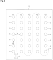
- the work vehicle 1 automatically travels in a field H where a crop S is planted in a row and sprays a chemical liquid on the crop S.
- the crop S is a fruit tree and the field H is an orchard.
- the row of the crop S is referred to as a crop row L.
- the row of the crop S arranged vertically is the crop row L.
- five crop rows L1 to L5 are laterally planted at intervals. In each crop row L1 to L5, a plurality of crops S are arranged at substantially equal intervals.
- crop rows L1 to L5 are referred to as a first crop row L1, a second crop row L2, a third crop row L3, a fourth crop row L4, and a fifth crop row L5 in order from the left.
- the lower side end of FIG. 3 is called a front side end
- the upper side end of FIG. 3 is called a back side end.
- the work vehicle 1 automatically travels between crop rows toward the back side end while using, for example, a vicinity of the front side end between the first crop row L1 and the second crop row L2, as an automatic travel start position and setting a target travel route between these crop rows.
- the work vehicle 1 reaches the back side end between the crop rows, the work vehicle 1 turns to the right in the traveling direction, and moves to the back side end between the second crop row L2 and the third crop row L3. Then, the work vehicle 1 automatically travels between crop rows toward the front side end while setting the target travel route between the second crop row L2 and the third crop row L3.
- the work vehicle 1 When the work vehicle 1 reaches the front side end between the crop rows L2 and L3, the work vehicle 1 turns to the left toward the traveling direction and moves to the front side end between the third crop row L3 and the fourth crop row L4. Then, the work vehicle 1 automatically travels between crop rows toward the back side end while setting the target travel route between the third crop row L3 and the fourth crop row L4. By the same operation, the work vehicle 1 moves as illustrated by the broken line in FIG. 3 . Then, for example, after the work vehicle 1 reaches the front side end between the fourth crop row L4 and the fifth crop row L5 and turns to the left toward the traveling direction, the automatic traveling is stopped. During automatic traveling, the pump 9A is driven via the clutch mechanism 9B, and the chemical liquid is ejected from the nozzles 8a and 8b.
- the end on the side where the work vehicle 1 starts traveling may be referred to as a traveling start end between the crop rows, and the end on the side opposite to the traveling start end may be called a traveling termination end between the crop rows.
- an interval W between adjacent crop rows may be called a row interval.
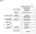
- FIG. 4 is a block diagram illustrating a main electrical configuration of the work vehicle 1.
- the work vehicle 1 includes a control device 30 for controlling the operation of the work vehicle 1.
- the distance sensor 13 Connected to the control device 30 are the distance sensor 13, a direction sensor 14, an engine controller 21, a travel controller 22, a clutch actuator 23, a storage unit 24, and the like.
- the distance sensor 13 detects information on a distance from the work vehicle to each of a plurality of objects present in the field H.
- the main target of the plurality of objects is the crop S.
- the direction sensor 14 is, as described above, for detecting the direction of the work vehicle 1.
- the engine controller 21 controls the number of revolutions of the engine 5, or the like. Specifically, the engine controller 21 controls a common rail device 16 as a fuel injection device provided in the engine 5, thereby controlling the number of revolutions of the engine 5. The engine controller 21 controls the common rail device 16, and thereby can also stop the supply of fuel to the engine 5 and stop the drive of the engine 5.
- the travel controller 22 controls forward, backward, turning, and stopping of the work vehicle 1 by controlling the crawler control mechanism 15.
- the clutch actuator 23 is for fastening and releasing the clutch mechanism 9B in the pump unit 9.
- the storage unit 24 includes a storage device such as a hard disk and a non-volatile memory.
- the control device 30 includes a microcomputer including a central processing unit (CPU) and a memory (read-only memory, or ROM, random-access memory, or RAM, etc.) 31.
- the control device 30 includes an automatic travel control unit 32 for causing the work vehicle 1 to automatically travel along a target travel route while setting the target travel route between adjacent crop rows L in the field H.
- the automatic travel control unit 32 includes a rectangle identification unit 41, a target setting unit 42, a deviation calculation unit 43, and a correction unit 44.
- the rectangle identification unit 41 estimates the plurality of crop rows on the basis of information on a distance from the work vehicle 1 to each of a plurality of objects present in the field H and identifies a rectangle whose opposite sides are adjacent crop rows of the estimated crop rows.
- the information on the distance from the work vehicle 1 to each of the plurality of objects present in the field H is the distance information to each object detected by the distance sensor 13. The operation of the rectangle identification unit 41 will be described in detail below.
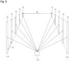
- FIG. 5 is a schematic perspective view illustrating a state where a laser light is emitted from the distance sensor 13 to the crop S included in a crop row.
- FIG. 6 is a schematic plan view of FIG. 5 seen from above.
- FIGs. 5 and 6 illustrate two adjacent crop rows La and Lb.
- a coordinate system in which a laser light output position at the distance sensor 13 is an origin O, a straight line passing through the origin O and parallel to the right-left direction of the work vehicle 1 is an X axis, and a straight line passing through the origin O and parallel to the front-rear direction of the work vehicle 1 is a Y axis is called a sensor coordinate system.
- the laser light is emitted from the distance sensor 13 in a different direction.
- a laser light emitting direction (emission angle) ⁇ is an angle between the +X axis and the laser light, and expressed as an angle counterclockwise around the origin O.
- the combination of the distance r and the emission angle ⁇ (r, ⁇ ) is acquired as distance information for the object.
- the X coordinate value x and the Y coordinate value y of the sensor coordinate system of the object whose distance information is (r, ⁇ ) are expressed by the following formula (1).
- the rectangle identification unit 41 first detects a position (x, y) of each object whose distance from the distance sensor 13 has been detected, on the basis of the aforementioned formula (1).
- the rectangle identification unit 41 detects a plurality of crop rows L on the basis of the position (x, y) of each object.
- the rectangle identification unit 41 selects, as a target crop row pair, for example, a crop row pair that is arranged in such a manner that two adjacent crop rows sandwich a straight line passing through the center of the work vehicle 1 and extending in the front-rear direction of the work vehicle 1.
- the rectangle identification unit 41 identifies the target crop row pair as a rectangle (rectangle or square) whose opposite sides are two crop rows constituting the target crop row pair. In other words, the rectangle identification unit 41 identifies a rectangle that approximates the target crop row pair.
- this process is called a rectangle identification process.
- one of the two adjacent sides of the rectangle is called a first side, and the other side is called a second side.
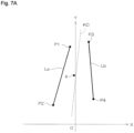
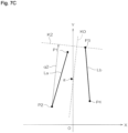
- the rectangle identification unit 41 first calculates a center of gravity g and a slope a of the target crop row pair. Specifically, the rectangle identification unit 41 acquires the coordinates of end points P1 and P2 of the crop row La and the coordinates of end points P3 and P4 of the crop row Lb. Then, the rectangle identification unit 41 calculates the center of gravity of a quadrangle having these four points as vertices as the center of gravity g of the target crop row pair.
- the slope a of the target crop row pair is, for example, the slope of a straight line K0 that passes through almost the center between the two crop rows La and Lb, and can be calculated by, for example, a least-squares method.
- the slope a of the target crop row pair thus calculated may be referred to as a "first slope a1".
- the rectangle identification unit 41 obtains a first straight line K1 passing through an end point (P4 in this example) having the largest X coordinate value among the end points P1 to P4 and having a first slope a1. Then, the rectangle identification unit 41 calculates the distance between the first straight line K1 and an end point (P2 in this example) having the smallest X coordinate value among the end points P1 to P4, as a length q1 of the first side.
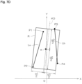
- the rectangle identification unit 41 obtains the slope of a straight line orthogonal to the straight line having the first slope a1 in the XY plane, as a second slope a2. Then, as illustrated in FIG. 7 , the rectangle identification unit 41 obtains a second straight line K2 passing through an end point (P3 in this example) having the largest Y coordinate value among the end points P1 to P4 and having the second slope a2. Then, the rectangle identification unit 41 calculates the distance between the second straight line K2 and an end point (P2 in this example) having the smallest Y coordinate value among the end points P1 to P4, as a length q2 of the second side.
- the rectangle identification unit 41 identifies, as a rectangle that approximates the target crop row pair, a rectangle having the aforementioned center of gravity g as the center of gravity, the first side whose slope is the second slope a2 and whose length is q1, and the second side whose slope is the first slope a1 and whose length is q2.
- a rectangle that approximates this target crop row pair will be as illustrated by R in FIG. 7D .
- the rectangle identification unit 41 may obtain a rectangle that approximates the target crop row pair by a method other than the method described above.
- a method for obtaining the rectangle that approximates the target crop row pair for example, various methods described as background art and various methods described as embodiments of Japanese Unexamined Patent Application Publication No. 2010-108135 can be used.
- the target setting unit 42 sets the target travel route and the target direction of the work vehicle 1 between the two crop rows constituting the selected crop row pair, on the basis of the rectangle identified by the rectangle identification unit 41.
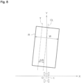
- the target setting unit 42 specifies the interval between the right and left sides of a rectangle R as a row interval W of the target crop row pair, as illustrated in FIG. 8 .
- the target setting unit 42 specifies the straight line that passes through the center of the right and left sides of the rectangle R, as a center line CL of the target crop row pair. Then, the target setting unit 42 sets, as a target travel route T, a straight line deviated to the side of one crop row (the left crop row La in the example of FIG. 8 ) by a predetermined offset amount ⁇ W, and at the same time sets a direction along the target travel route T as the target direction.
- the direction for deviating by the offset amount ⁇ W with respect to the center line CL differs depending on the target crop row pair. For example, when the first crop row L1 and the second crop row L2 in FIG. 3 are the target crop row pair, the direction for deviating by the offset amount ⁇ W with respect to the center line CL is the direction of the first crop row L1 side (left side toward the traveling direction). Meanwhile, when the second crop row L2 and the third crop row L3 in FIG. 3 are the target crop row pair, direction for deviating by the offset amount ⁇ W with respect to the center line CL is the direction of the second crop row L2 side (right side toward the traveling direction).
- the deviation calculation unit 43 calculates a deviation amount from the target travel route T and the deviation amount from the target direction.
- the deviation calculation unit 43 includes a position deviation calculation unit 43A and a direction deviation calculation unit 43B.
- the position deviation calculation unit 43A estimates the current position of the work vehicle 1 between the two crop rows constituting the target crop row pair on the basis of the rectangle R identified by the rectangle identification unit 41, and calculates a deviation amount (position deviation amount) of the current position from the target travel route.
- the direction deviation calculation unit 43B calculates a deviation amount (direction deviation amount) of the current direction of the work vehicle 1 detected by the direction sensor 14, from the target direction.
- the position deviation calculation unit 43A converts the position and direction of the work vehicle 1 in the sensor coordinate system, into the position and direction of the crop row coordinate system in which the target travel route T is a Y' axis and a line that is orthogonal to the Y' axis and passes through the center of gravity of the work vehicle 1 is an X' axis.
- the converted position and direction of the work vehicle 1 correspond to the current position and direction of the work vehicle 1 between the two crop rows constituting the target crop row pair.
- the position deviation calculation unit 43A sets, as a target position Q, a position that has advanced in the traveling direction by a predetermined distance f along the target travel route T from the origin O' of the crop row coordinate system. Then, the position deviation calculation unit 43A calculates an angle ⁇ between the straight line connecting the target position Q and the center of gravity position G of the work vehicle 1 and the Y' axis, as the position deviation amount (position deviation angle) of the work vehicle 1 with respect to the target travel route T. If the distance between the origin O' and the center of gravity position G of the work vehicle 1 is ⁇ x, the position deviation amount ⁇ can be calculated from the following formula (2).
- the direction deviation calculation unit 43B calculates an angle ⁇ formed by the orientation (front-rear direction) of the work vehicle 1 and the target direction (Y' axis) as the direction deviation amount.
- the direction deviation amount ⁇ can be calculated in the same manner as the position deviation amount ⁇ by obtaining a Y' coordinate value of the intersection of the Y' axis and a straight line passing through the center of gravity G of the work vehicle 1 and extending in the front-rear direction of the work vehicle 1
- the correction unit 44 includes a position correction unit 44A and a direction correction unit 44B.
- the position correction unit 46A corrects the position of the work vehicle 1 between the crop rows in such a manner that the position approaches the target travel route T, on the basis of the position deviation amount ⁇ calculated by the position deviation calculation unit 43A.
- the direction correction unit 44B corrects the direction of the work vehicle 1 between the crop rows in such a manner that the direction approaches the target direction, on the basis of the direction deviation amount ⁇ calculated by the direction deviation calculation unit 43B. That is, in this embodiment, the correction unit 44 controls the crawler control mechanism 15 in such a manner that the position deviation amount ⁇ approaches zero and the direction deviation amount ⁇ approaches zero.
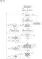
- FIG. 10 is a flowchart illustrating an overall procedure of an automatic travel control process by the automatic travel control unit 32.
- the operation modes of the work vehicle 1 include a search mode and a run mode.
- the search mode refers to a mode for setting the target travel route and target direction, and the like by performing a crop row identification process before entering between crop rows.
- the crop row identification process refers to a process performed by the rectangle identification unit 41, target setting unit 42, and deviation calculation unit 43 to set the target travel route T and target direction and calculate the row interval W, the position deviation amount ⁇ from the target travel route T, the direction deviation amount ⁇ from the target direction, and the like.
- the run mode is a mode in which the work vehicle 1 caused to travel in such a manner that the position deviation amount ⁇ and the direction deviation amount ⁇ approach zero while performing the crop row identification process.
- the user When performing an automatic travel control, the user sets the row interval W and a target number of turns N to the work vehicle 1.
- the target number of turns N is the number of turns of the work vehicle 1 expected to be performed before the work vehicle 1 reaches a position at which automatic operation should be stopped after it is started.
- the row interval W and the target number of turns N set by the user are stored in the memory 31.
- the user moves the work vehicle 1 to the vicinity of the start position of automatic travel by, for example, a remote control. Then, the user starts the automatic travel control by, for example, a remote control.
- the automatic travel control unit 32 sets the operation mode to a search mode (step S1). Then, the automatic travel control unit 32 determines if the number of turns of the work vehicle 1 has reached the target number of turns N.
- step S2 If the number of turns of the work vehicle 1 has not reached the target number of turns N (step S2: NO), the automatic travel control unit 32 performs the crop row identification process described above (step S3).
- the automatic travel control unit 32 determines whether the crop row detection is successful (step S4). Specifically, the automatic travel control unit 32 determines that the crop row detection is successful if a success or failure condition is fulfilled in which the position deviation amount ⁇ calculated by the crop row identification process is within a first predetermined range and the direction deviation amount ⁇ calculated by the crop row identification process is within a second predetermined range. On the other hand, if the target crop row pair is not specified by the crop row identification process, or if the target crop row pair is specified and the success or failure determination condition is not fulfilled, the automatic travel control unit 32 determines that the crop row detection has failed.
- step S4 determines whether the operation mode is the search mode (step S5). If the operation mode is the search mode (step S5: YES), the automatic travel control unit 32 changes the position of the work vehicle 1 and moves the work vehicle 1 again to perform the crop row identification process (step S6).
- the automatic travel control unit 32 may simply retract the work vehicle 1 by a predetermined amount when the target crop row pair is not specified in the crop row identification process of step S3. On the other hand, when the target crop row pair is specified in the crop row identification process of step S3, the automatic travel control unit 32 may move the work vehicle 1 to the center position side between the two crop rows constituting the target crop row pair. When the process of step S6 is completed, the automatic travel control unit 32 returns to step S2.
- step S5 if it is determined that the operation mode is the run mode (step S5: NO), the automatic travel control unit 32 returns to step S2.
- step S4 if it is determined that the crop row detection is successful (step S4: YES), the automatic travel control unit 32 updates the row interval W in the memory 31 (step S7). Specifically, the automatic travel control unit 32 rewrites the row interval W stored in the memory 31 to the row interval W acquired by the crop row identification process of step S3.
- the automatic travel control unit 32 determines whether the operation mode is the search mode (step S8). If the operation mode is the search mode (step S8: YES), the automatic travel control unit 32 sets a reference direction (step S9). Specifically, the automatic travel control unit 32 uses the direction deviation amount ⁇ calculated in step S3 and the direction of the work vehicle 1 currently detected by the direction sensor 14 to convert the target direction set in step S3 into the direction detected by the direction sensor 14. Then, the automatic travel control unit 32 stores the converted direction in the memory 31 as the reference direction. In this way, the difference between the direction of the work vehicle 1 detected by the direction sensor 14 and the reference direction can be detected as the direction deviation amount of the direction of the work vehicle 1 with respect to the target direction.
- the automatic travel control unit 32 sets the operation mode to the run mode (step S10). Then, the automatic travel control unit 32 proceeds to step S11. In the run mode, the correction unit 44 of the automatic travel control unit 32 controls the crawler control mechanism 15 in such a manner that the position deviation amount ⁇ and the direction deviation amount ⁇ approach zero.
- step S8 if it is determined that the operation mode is the run mode (step S8: NO), the automatic travel control unit 32 proceeds to step S11.
- step S11 the automatic travel control unit 32 determines whether the determination result of step S4 is that the crop row detection has succeeded at least a predetermined number of times in succession.
- step S4 determines whether the crop row detection has succeeded at least a predetermined number of times in succession. If the determination result in step S4 is that the crop row detection has succeeded at least a predetermined number of times in succession (step S11: YES), the automatic travel control unit 32 updates the reference direction (step S12). Specifically, the automatic travel control unit 32 uses the direction deviation amount ⁇ set in step S3 and the direction of the work vehicle 1 currently detected by the direction sensor 14 to convert the target direction set in step S3 into the direction detected by the direction sensor 14. Then, the automatic travel control unit 32 rewrites the reference direction stored in the memory 31 to the converted direction. After this, the automatic travel control unit 32 proceeds to step S13.
- step S11 if it is determined that the determination result of step S4 is not that the crop row detection has succeeded at least a predetermined number of times in succession (step S 11: NO), the automatic travel control unit 32 does not update the reference direction, and proceeds to step S13.
- the reference direction is updated only if the determination result of step S4 is that the crop row detection has succeeded at least a predetermined number of times in succession. This is to prevent the reference direction from being updated when the crop row identification process is not performed accurately due to the effect of noise or the like.
- step S13 the automatic travel control unit 32 determines whether the work vehicle 1 has reached the traveling termination end (row end) between the crop rows.
- the automatic travel control unit 32 starts to measure the traveling distance, for example, when the work vehicle 1 reaches a front position by a predetermined distance from the traveling termination end between the target crop row pair, and determines that the work vehicle 1 has reached the traveling termination end between the crop rows when the measured traveling distance reaches the aforementioned predetermined distance.
- the automatic travel control unit 32 may start measuring time when the work vehicle 1 reaches the front position by a predetermined distance from the traveling termination end between the target crop row pair, and may determine that the work vehicle 1 has reached the traveling termination end between the crop rows when a time required for the work vehicle 1 to travel the predetermined distance has elapsed.
- step S13 NO
- the automatic travel control unit 32 returns to step S2.
- step S13 if it is determined that the work vehicle 1 has reached the traveling termination end between the target crop row pair (step S13:YES), the automatic travel control unit 32 turns the work vehicle 1 in order to move the work vehicle 1 to the traveling start end between the next crop rows (step S14). Specifically, the automatic travel control unit 32 controls the crawler control mechanism 15 to turn the work vehicle 1 approximately 180 degrees in a predetermined turning direction. The turning radius is set to 1/2 of the row interval W stored in the memory 31.
- the predetermined turning direction is determined on the basis of the preset turning direction at the first traveling termination end and information on the number of turns as of the current turn. For example, when the turning direction at the first traveling termination end is to the right, if the current turn is an odd number, the turning direction is to the right, and if the current turn is an even number, the turning direction is to the left. On the other hand, when the turning direction at the first traveling termination end is to the left, if the current turn is an odd number the turning direction is to the left, and if the current turn is an even number, the turning direction is to the right.
- step S14 the automatic travel control unit 32 returns to step S2.
- step S2 when it is determined that the number of turns of the work vehicle 1 has reached the target number of turns N (step S2: YES), the automatic travel control unit 32 ends the automatic travel control.
- the automatic travel control unit 32 returns to step S2 after the turning in step S14, but may return to step S1 after the turning in step S14.
- the operation mode is set to the search mode, and thus the work vehicle is temporarily stopped.
- the adjacent crop rows L may not be straight but may be bent in the middle.
- the slopes of the adjacent crop rows L may change in the middle.
- the target direction (reference direction) is updated on the basis of the rectangle identified by the crop row identification process (see step S3) during automatic traveling, the target direction of the work vehicle 1 can be changed in accordance with the change in the slopes of the crop rows.
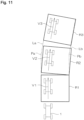
- the description will be given with the use of FIG. 11 .
- the two crop rows La and Lb constituting the target crop row pair are respectively bent to the right near intermediate positions Pa and Pb in the length direction.
- the work vehicle 1 is assumed to automatically travel between the crop rows La and Lb from the lower side to the upper side of the paper surface of FIG. 11 .
- the lower side end between the crop rows in FIG. 11 is the traveling start point and the upper side end between the crop rows is the traveling end point.
- the automatic travel control unit 32 identifies a first rectangle R1 corresponding to the portion from the traveling start point between the crop rows La and Lb to bending points Pa and Pb of the crop rows La and Lb.
- the slope (target direction) of both the right and left sides of the first rectangle R1 is an angle according to the average slope of the portion from the traveling start point in the crop rows La and Lb to the bending points Pa and Pb of the crop rows La and Lb. Therefore, the work vehicle 1 travels as indicated by an arrow V1.
- the automatic travel control unit 32 identifies a second rectangle R2 corresponding to the portion including the bending points Pa and Pb in the crop rows La and Lb in the middle in the length direction.
- the slope (target direction) of both the right and left sides of the second rectangle R2 is an angle according to the average slope of the portion including the bending points Pa and Pb in the crop rows La and Lb in the middle in the length direction. Therefore, the slope of the second rectangle R2 is an angle inclined to the right toward the traveling direction with respect to the slope of the first rectangle R1.
- the target direction reference direction
- the work vehicle 1 travels as indicated by an arrow V2.
- the automatic travel control unit 32 identifies a third rectangle R3 corresponding to a portion further to the traveling termination end side than the bending points Pa and Pb in the crop rows La and Lb.
- the slope (target direction) of both the right and left sides of the third rectangle R3 is an angle according to the average slope of the portion further to the traveling termination end side than the bending points Pa and Pb in the crop rows La and Lb. Therefore, the slope of the third rectangle R3 is an angle further inclined to the right toward the traveling direction with respect to the slope of the second rectangle R2.
- the target direction reference direction
- the work vehicle 1 travels as indicated by an arrow V3. In this way, the work vehicle 1 travels along the target travel route according to the shape of the crop rows La and Lb even when the crop rows La and Lb are bent in the middle.
- a rectangle whose opposite sides are adjacent crop rows is identified, and on the basis of the identified rectangle, the target travel route and the target direction are set, and at the same time the current position of the work vehicle is estimated. Therefore, for example, when the slopes of adjacent crop rows change in the middle, such as when the adjacent crop rows bend in the middle, a rectangle according to a slope near the work vehicle in the adjacent crop rows is identified. This makes it possible to set a target travel route between adjacent crop rows corresponding to changes in the slopes of these crop rows, and to estimate the position of the work vehicle 1 between both crop rows.
- the work vehicle 1 is moved to the automatic travel start position by remote control.
- the work vehicle 1 may be transported to the automatic travel start position by a truck or the like.
- the work vehicle 1 may be manually operated and may be moved to the automatic travel start position by the manual operation.
- the LIDAR is used as the distance sensor 13, but a distance sensor other than LIDAR such as a monocular camera or a stereo camera may be used.
- the work vehicle is a work vehicle for spraying a chemical liquid
- the work vehicle may be a work vehicle for other than spraying a chemical liquid.
Landscapes
- Engineering & Computer Science (AREA)
- Radar, Positioning & Navigation (AREA)
- Remote Sensing (AREA)
- Life Sciences & Earth Sciences (AREA)
- Soil Sciences (AREA)
- Environmental Sciences (AREA)
- Mechanical Engineering (AREA)
- Automation & Control Theory (AREA)
- Physics & Mathematics (AREA)
- General Physics & Mathematics (AREA)
- Guiding Agricultural Machines (AREA)
- Control Of Position, Course, Altitude, Or Attitude Of Moving Bodies (AREA)
- Navigation (AREA)
- Traffic Control Systems (AREA)
Claims (6)
- Véhicule de travail configuré pour se déplacer dans un champ où une pluralité de rangs de culture sont plantés, le véhicule de travail comprenant :un capteur de distance configuré pour acquérir des informations sur une distance entre le véhicule de travail et chacun d'une pluralité d'objets présents dans le champ ;caractérisé parune unité d'identification de rectangle configurée pour estimer la pluralité de rangs de culture sur la base des informations de distance et identifier un rectangle dont les côtés opposés sont des rangs de culture adjacents des rangs de culture estimés ;une unité de définition de cible configurée pour définir un itinéraire de déplacement cible du véhicule de travail entre les rangs de culture adjacents sur la base du rectangle ; etune unité de calcul d'écart de position configurée pour estimer une position actuelle du véhicule de travail entre les rangs de culture adjacents sur la base du rectangle et calculer une quantité d'écart de la position actuelle par rapport à l'itinéraire de déplacement cible.
- Véhicule de travail selon la revendication 1, comprenant en outre une unité de correction de position configurée pour corriger une position du véhicule de travail entre les rangs de culture de telle manière que la position se rapproche de l'itinéraire de déplacement cible, sur la base de la quantité d'écart calculée par l'unité de calcul d'écart de position.
- Véhicule de travail selon la revendication 1 ou 2, comprenant en outre un capteur de direction configuré pour détecter une direction du véhicule de travail,dans lequel l'unité de définition de cible est configurée également pour définir une direction cible du véhicule de travail, etdans lequel le véhicule de travail comporte en outre une unité de calcul d'écart de direction configurée pour calculer une quantité d'écart d'une direction actuelle du véhicule de travail détectée par le capteur de direction, par rapport à la direction cible.
- Véhicule de travail selon la revendication 3, comprenant en outre une unité de correction de direction configurée pour corriger une direction du véhicule de travail entre les rangs de culture de telle manière que la direction se rapproche de la direction cible, sur la base de la quantité d'écart calculée par l'unité de calcul d'écart de direction.
- Véhicule de travail selon la revendication 3 ou 4,dans lequel l'unité d'identification de rectangle identifie de manière répétée le rectangle tandis que le véhicule de travail se déplace entre les rangs de culture,dans lequel l'unité de définition de direction cible définit la direction cible sur la base du rectangle chaque fois que le rectangle est identifié, etdans lequel l'unité de calcul d'écart de direction calcule une quantité d'écart d'une direction actuelle du véhicule de travail, détectée par le capteur de direction, par rapport à la direction cible, chaque fois que la direction cible est définie.
- Programme de calcul de quantité d'écart qui définit un itinéraire de déplacement cible d'un véhicule de travail dans un champ où une pluralité de rangs de culture sont plantés et qui calcule une quantité d'écart du véhicule de travail par rapport à l'itinéraire de déplacement cible, le programme de calcul de quantité d'écart amenant un ordinateur à fonctionner comme :une unité d'identification de rectangle pour estimer la pluralité de rangs de culture sur la base d'informations sur une distance entre le véhicule de travail et chacun d'une pluralité d'objets présents dans le champ et pour identifier un rectangle dont les côtés opposés sont des rangs de culture adjacents des rangs de culture estimés ;une unité de définition de cible pour définir un itinéraire de déplacement cible du véhicule de travail entre les rangs de culture adjacents sur la base du rectangle ; etune unité de calcul d'écart de position pour estimer une position actuelle entre les rangs de culture adjacents sur la base du rectangle et calculer une quantité d'écart de la position actuelle par rapport à l'itinéraire de déplacement cible.
Applications Claiming Priority (2)
| Application Number | Priority Date | Filing Date | Title |
|---|---|---|---|
| JP2018048450A JP6735301B2 (ja) | 2018-03-15 | 2018-03-15 | 作業車両およびずれ量算出プログラム |
| PCT/JP2019/009638 WO2019176842A1 (fr) | 2018-03-15 | 2019-03-11 | Machine agricole et programme de calcul de degré d'écart |
Publications (3)
| Publication Number | Publication Date |
|---|---|
| EP3766321A1 EP3766321A1 (fr) | 2021-01-20 |
| EP3766321A4 EP3766321A4 (fr) | 2021-12-15 |
| EP3766321B1 true EP3766321B1 (fr) | 2023-05-03 |
Family
ID=67906682
Family Applications (1)
| Application Number | Title | Priority Date | Filing Date |
|---|---|---|---|
| EP19768156.2A Active EP3766321B1 (fr) | 2018-03-15 | 2019-03-11 | Machine agricole et programme de calcul de degré d'écart |
Country Status (3)
| Country | Link |
|---|---|
| EP (1) | EP3766321B1 (fr) |
| JP (1) | JP6735301B2 (fr) |
| WO (1) | WO2019176842A1 (fr) |
Families Citing this family (3)
| Publication number | Priority date | Publication date | Assignee | Title |
|---|---|---|---|---|
| AT523999A1 (de) * | 2020-06-19 | 2022-01-15 | Ideas Gmbh & Co Kg | Vorrichtung an Landmaschinen zur Abtastung von Konturen sowie Verfahren zur Steuerung der Landmaschine |
| WO2022118338A1 (fr) * | 2020-12-01 | 2022-06-09 | Hachidori Robotics Private Limited | Système et procédé de détermination de position et d'orientation absolues instantanées d'une entité dans un espace de navigation |
| KR102691520B1 (ko) * | 2021-12-07 | 2024-08-05 | 대한민국 | LiDAR 기반 과수 인식 및 작업자 추종이 가능한 전자 장치, 이를 포함하는 자율 주행 농기계 및 자율 주행 제어 방법 |
Family Cites Families (5)
| Publication number | Priority date | Publication date | Assignee | Title |
|---|---|---|---|---|
| JPH0787725B2 (ja) * | 1988-02-10 | 1995-09-27 | 株式会社クボタ | 作業車用の操向制御情報検出装置 |
| JPH11275912A (ja) | 1998-03-26 | 1999-10-12 | Iseki & Co Ltd | 収穫機 |
| JP4738469B2 (ja) | 2008-10-29 | 2011-08-03 | 株式会社東芝 | 画像処理装置、画像処理プログラムおよび画像処理方法 |
| JP6418604B2 (ja) | 2015-04-30 | 2018-11-07 | 国立大学法人 鹿児島大学 | 作業機及びその制御方法 |
| JP6872767B2 (ja) | 2016-09-20 | 2021-05-19 | 株式会社杉孝グループホールディングス | 吊り足場の支持構造、支持方法及び構築方法 |
-
2018
- 2018-03-15 JP JP2018048450A patent/JP6735301B2/ja active Active
-
2019
- 2019-03-11 WO PCT/JP2019/009638 patent/WO2019176842A1/fr active Application Filing
- 2019-03-11 EP EP19768156.2A patent/EP3766321B1/fr active Active
Also Published As
| Publication number | Publication date |
|---|---|
| EP3766321A1 (fr) | 2021-01-20 |
| JP2019154377A (ja) | 2019-09-19 |
| WO2019176842A1 (fr) | 2019-09-19 |
| JP6735301B2 (ja) | 2020-08-05 |
| EP3766321A4 (fr) | 2021-12-15 |
Similar Documents
| Publication | Publication Date | Title |
|---|---|---|
| EP3766320B1 (fr) | Véhicule de travail et programme de reconnaissance de rangée de récolte | |
| EP3766322B1 (fr) | Véhicule de travail et programme d'identification de rangée de culture | |
| EP3766321B1 (fr) | Machine agricole et programme de calcul de degré d'écart | |
| EP3833176B1 (fr) | Navigation et entraînement de machine autonome faisant appel à un système de vision | |
| US10197407B2 (en) | Method and robot system for autonomous control of a vehicle | |
| KR20170091110A (ko) | 작업 차량 | |
| JP2004008186A (ja) | 農業用作業車 | |
| JP5328427B2 (ja) | 走行制御装置 | |
| JP6562678B2 (ja) | 自動走行作業車両 | |
| JP7433362B2 (ja) | 走行経路生成システム | |
| JP6851589B2 (ja) | 作業車 | |
| CN116267069A (zh) | 行驶作业机、插秧机、水田直播机、喷雾作业机 | |
| US11753076B2 (en) | Automated hitching system with subject trailer selection from multiple identified trailers | |
| JP6626668B2 (ja) | 農作業機用案内システム | |
| JP6991050B2 (ja) | 走行作業機 | |
| JP2019097504A (ja) | 走行作業機 | |
| JP2016187305A (ja) | 移動農機 | |
| JP2018139519A (ja) | 散布システム | |
| US11809188B2 (en) | Traveling work machine | |
| JP7069002B2 (ja) | 圃場作業車及び圃場地図データ生成システム | |
| JP7318764B2 (ja) | 作業車両 | |
| JP6884339B2 (ja) | 作業車 | |
| JP6740116B2 (ja) | 移動車両 | |
| JP2017136012A (ja) | 作業機及び作業システム | |
| JP2020010719A (ja) | 農作業機用案内システム |
Legal Events
| Date | Code | Title | Description |
|---|---|---|---|
| STAA | Information on the status of an ep patent application or granted ep patent |
Free format text: STATUS: THE INTERNATIONAL PUBLICATION HAS BEEN MADE |
|
| PUAI | Public reference made under article 153(3) epc to a published international application that has entered the european phase |
Free format text: ORIGINAL CODE: 0009012 |
|
| STAA | Information on the status of an ep patent application or granted ep patent |
Free format text: STATUS: REQUEST FOR EXAMINATION WAS MADE |
|
| 17P | Request for examination filed |
Effective date: 20201001 |
|
| AK | Designated contracting states |
Kind code of ref document: A1 Designated state(s): AL AT BE BG CH CY CZ DE DK EE ES FI FR GB GR HR HU IE IS IT LI LT LU LV MC MK MT NL NO PL PT RO RS SE SI SK SM TR |
|
| AX | Request for extension of the european patent |
Extension state: BA ME |
|
| DAV | Request for validation of the european patent (deleted) | ||
| DAX | Request for extension of the european patent (deleted) | ||
| A4 | Supplementary search report drawn up and despatched |
Effective date: 20211115 |
|
| RIC1 | Information provided on ipc code assigned before grant |
Ipc: G01S 17/89 20200101ALI20211109BHEP Ipc: G01S 7/48 20060101ALI20211109BHEP Ipc: G01C 21/20 20060101ALI20211109BHEP Ipc: G01C 21/00 20060101ALI20211109BHEP Ipc: A01B 69/04 20060101ALI20211109BHEP Ipc: A01B 69/00 20060101AFI20211109BHEP |
|
| GRAP | Despatch of communication of intention to grant a patent |
Free format text: ORIGINAL CODE: EPIDOSNIGR1 |
|
| STAA | Information on the status of an ep patent application or granted ep patent |
Free format text: STATUS: GRANT OF PATENT IS INTENDED |
|
| INTG | Intention to grant announced |
Effective date: 20221205 |
|
| GRAS | Grant fee paid |
Free format text: ORIGINAL CODE: EPIDOSNIGR3 |
|
| GRAA | (expected) grant |
Free format text: ORIGINAL CODE: 0009210 |
|
| STAA | Information on the status of an ep patent application or granted ep patent |
Free format text: STATUS: THE PATENT HAS BEEN GRANTED |
|
| AK | Designated contracting states |
Kind code of ref document: B1 Designated state(s): AL AT BE BG CH CY CZ DE DK EE ES FI FR GB GR HR HU IE IS IT LI LT LU LV MC MK MT NL NO PL PT RO RS SE SI SK SM TR |
|
| REG | Reference to a national code |
Ref country code: GB Ref legal event code: FG4D |
|
| REG | Reference to a national code |
Ref country code: AT Ref legal event code: REF Ref document number: 1563812 Country of ref document: AT Kind code of ref document: T Effective date: 20230515 Ref country code: CH Ref legal event code: EP |
|
| REG | Reference to a national code |
Ref country code: DE Ref legal event code: R096 Ref document number: 602019028431 Country of ref document: DE |
|
| REG | Reference to a national code |
Ref country code: IE Ref legal event code: FG4D |
|
| REG | Reference to a national code |
Ref country code: LT Ref legal event code: MG9D |
|
| REG | Reference to a national code |
Ref country code: NL Ref legal event code: MP Effective date: 20230503 |
|
| REG | Reference to a national code |
Ref country code: AT Ref legal event code: MK05 Ref document number: 1563812 Country of ref document: AT Kind code of ref document: T Effective date: 20230503 |
|
| PG25 | Lapsed in a contracting state [announced via postgrant information from national office to epo] |
Ref country code: SE Free format text: LAPSE BECAUSE OF FAILURE TO SUBMIT A TRANSLATION OF THE DESCRIPTION OR TO PAY THE FEE WITHIN THE PRESCRIBED TIME-LIMIT Effective date: 20230503 Ref country code: PT Free format text: LAPSE BECAUSE OF FAILURE TO SUBMIT A TRANSLATION OF THE DESCRIPTION OR TO PAY THE FEE WITHIN THE PRESCRIBED TIME-LIMIT Effective date: 20230904 Ref country code: NO Free format text: LAPSE BECAUSE OF FAILURE TO SUBMIT A TRANSLATION OF THE DESCRIPTION OR TO PAY THE FEE WITHIN THE PRESCRIBED TIME-LIMIT Effective date: 20230803 Ref country code: NL Free format text: LAPSE BECAUSE OF FAILURE TO SUBMIT A TRANSLATION OF THE DESCRIPTION OR TO PAY THE FEE WITHIN THE PRESCRIBED TIME-LIMIT Effective date: 20230503 Ref country code: ES Free format text: LAPSE BECAUSE OF FAILURE TO SUBMIT A TRANSLATION OF THE DESCRIPTION OR TO PAY THE FEE WITHIN THE PRESCRIBED TIME-LIMIT Effective date: 20230503 Ref country code: AT Free format text: LAPSE BECAUSE OF FAILURE TO SUBMIT A TRANSLATION OF THE DESCRIPTION OR TO PAY THE FEE WITHIN THE PRESCRIBED TIME-LIMIT Effective date: 20230503 |
|
| PG25 | Lapsed in a contracting state [announced via postgrant information from national office to epo] |
Ref country code: RS Free format text: LAPSE BECAUSE OF FAILURE TO SUBMIT A TRANSLATION OF THE DESCRIPTION OR TO PAY THE FEE WITHIN THE PRESCRIBED TIME-LIMIT Effective date: 20230503 Ref country code: PL Free format text: LAPSE BECAUSE OF FAILURE TO SUBMIT A TRANSLATION OF THE DESCRIPTION OR TO PAY THE FEE WITHIN THE PRESCRIBED TIME-LIMIT Effective date: 20230503 Ref country code: LV Free format text: LAPSE BECAUSE OF FAILURE TO SUBMIT A TRANSLATION OF THE DESCRIPTION OR TO PAY THE FEE WITHIN THE PRESCRIBED TIME-LIMIT Effective date: 20230503 Ref country code: LT Free format text: LAPSE BECAUSE OF FAILURE TO SUBMIT A TRANSLATION OF THE DESCRIPTION OR TO PAY THE FEE WITHIN THE PRESCRIBED TIME-LIMIT Effective date: 20230503 Ref country code: IS Free format text: LAPSE BECAUSE OF FAILURE TO SUBMIT A TRANSLATION OF THE DESCRIPTION OR TO PAY THE FEE WITHIN THE PRESCRIBED TIME-LIMIT Effective date: 20230903 Ref country code: HR Free format text: LAPSE BECAUSE OF FAILURE TO SUBMIT A TRANSLATION OF THE DESCRIPTION OR TO PAY THE FEE WITHIN THE PRESCRIBED TIME-LIMIT Effective date: 20230503 Ref country code: GR Free format text: LAPSE BECAUSE OF FAILURE TO SUBMIT A TRANSLATION OF THE DESCRIPTION OR TO PAY THE FEE WITHIN THE PRESCRIBED TIME-LIMIT Effective date: 20230804 |
|
| PG25 | Lapsed in a contracting state [announced via postgrant information from national office to epo] |
Ref country code: FI Free format text: LAPSE BECAUSE OF FAILURE TO SUBMIT A TRANSLATION OF THE DESCRIPTION OR TO PAY THE FEE WITHIN THE PRESCRIBED TIME-LIMIT Effective date: 20230503 |
|
| PG25 | Lapsed in a contracting state [announced via postgrant information from national office to epo] |
Ref country code: SK Free format text: LAPSE BECAUSE OF FAILURE TO SUBMIT A TRANSLATION OF THE DESCRIPTION OR TO PAY THE FEE WITHIN THE PRESCRIBED TIME-LIMIT Effective date: 20230503 |
|
| PG25 | Lapsed in a contracting state [announced via postgrant information from national office to epo] |
Ref country code: SM Free format text: LAPSE BECAUSE OF FAILURE TO SUBMIT A TRANSLATION OF THE DESCRIPTION OR TO PAY THE FEE WITHIN THE PRESCRIBED TIME-LIMIT Effective date: 20230503 Ref country code: SK Free format text: LAPSE BECAUSE OF FAILURE TO SUBMIT A TRANSLATION OF THE DESCRIPTION OR TO PAY THE FEE WITHIN THE PRESCRIBED TIME-LIMIT Effective date: 20230503 Ref country code: RO Free format text: LAPSE BECAUSE OF FAILURE TO SUBMIT A TRANSLATION OF THE DESCRIPTION OR TO PAY THE FEE WITHIN THE PRESCRIBED TIME-LIMIT Effective date: 20230503 Ref country code: EE Free format text: LAPSE BECAUSE OF FAILURE TO SUBMIT A TRANSLATION OF THE DESCRIPTION OR TO PAY THE FEE WITHIN THE PRESCRIBED TIME-LIMIT Effective date: 20230503 Ref country code: DK Free format text: LAPSE BECAUSE OF FAILURE TO SUBMIT A TRANSLATION OF THE DESCRIPTION OR TO PAY THE FEE WITHIN THE PRESCRIBED TIME-LIMIT Effective date: 20230503 Ref country code: CZ Free format text: LAPSE BECAUSE OF FAILURE TO SUBMIT A TRANSLATION OF THE DESCRIPTION OR TO PAY THE FEE WITHIN THE PRESCRIBED TIME-LIMIT Effective date: 20230503 |
|
| REG | Reference to a national code |
Ref country code: DE Ref legal event code: R097 Ref document number: 602019028431 Country of ref document: DE |
|
| PLBE | No opposition filed within time limit |
Free format text: ORIGINAL CODE: 0009261 |
|
| STAA | Information on the status of an ep patent application or granted ep patent |
Free format text: STATUS: NO OPPOSITION FILED WITHIN TIME LIMIT |
|
| 26N | No opposition filed |
Effective date: 20240206 |
|
| PG25 | Lapsed in a contracting state [announced via postgrant information from national office to epo] |
Ref country code: SI Free format text: LAPSE BECAUSE OF FAILURE TO SUBMIT A TRANSLATION OF THE DESCRIPTION OR TO PAY THE FEE WITHIN THE PRESCRIBED TIME-LIMIT Effective date: 20230503 |
|
| PG25 | Lapsed in a contracting state [announced via postgrant information from national office to epo] |
Ref country code: SI Free format text: LAPSE BECAUSE OF FAILURE TO SUBMIT A TRANSLATION OF THE DESCRIPTION OR TO PAY THE FEE WITHIN THE PRESCRIBED TIME-LIMIT Effective date: 20230503 Ref country code: IT Free format text: LAPSE BECAUSE OF FAILURE TO SUBMIT A TRANSLATION OF THE DESCRIPTION OR TO PAY THE FEE WITHIN THE PRESCRIBED TIME-LIMIT Effective date: 20230503 |