EP3766071B1 - Method for data refresh for analog non-volatile memory in deep learning neural network - Google Patents
Method for data refresh for analog non-volatile memory in deep learning neural network Download PDFInfo
- Publication number
- EP3766071B1 EP3766071B1 EP19767098.7A EP19767098A EP3766071B1 EP 3766071 B1 EP3766071 B1 EP 3766071B1 EP 19767098 A EP19767098 A EP 19767098A EP 3766071 B1 EP3766071 B1 EP 3766071B1
- Authority
- EP
- European Patent Office
- Prior art keywords
- memory cell
- cells
- memory
- data
- array
- Prior art date
- Legal status (The legal status is an assumption and is not a legal conclusion. Google has not performed a legal analysis and makes no representation as to the accuracy of the status listed.)
- Active
Links
- 230000015654 memory Effects 0.000 title claims description 164
- 238000000034 method Methods 0.000 title claims description 34
- 238000013528 artificial neural network Methods 0.000 title description 26
- 238000013135 deep learning Methods 0.000 title description 2
- 238000012549 training Methods 0.000 claims description 2
- 210000004027 cell Anatomy 0.000 description 173
- 210000002569 neuron Anatomy 0.000 description 30
- 210000000225 synapse Anatomy 0.000 description 29
- 239000011159 matrix material Substances 0.000 description 20
- 238000003491 array Methods 0.000 description 19
- 230000006870 function Effects 0.000 description 17
- 230000008569 process Effects 0.000 description 13
- 239000000463 material Substances 0.000 description 10
- 239000000758 substrate Substances 0.000 description 7
- 230000004913 activation Effects 0.000 description 6
- 238000010586 diagram Methods 0.000 description 6
- 238000003860 storage Methods 0.000 description 5
- 238000001514 detection method Methods 0.000 description 4
- 230000014759 maintenance of location Effects 0.000 description 4
- 238000011176 pooling Methods 0.000 description 3
- 238000013139 quantization Methods 0.000 description 3
- 239000004065 semiconductor Substances 0.000 description 3
- 239000003990 capacitor Substances 0.000 description 2
- 238000013527 convolutional neural network Methods 0.000 description 2
- 238000005516 engineering process Methods 0.000 description 2
- 230000007246 mechanism Effects 0.000 description 2
- 238000005070 sampling Methods 0.000 description 2
- 230000005689 Fowler Nordheim tunneling Effects 0.000 description 1
- 241001465754 Metazoa Species 0.000 description 1
- 241001661355 Synapsis Species 0.000 description 1
- 230000003044 adaptive effect Effects 0.000 description 1
- 230000002411 adverse Effects 0.000 description 1
- 238000013459 approach Methods 0.000 description 1
- 238000013529 biological neural network Methods 0.000 description 1
- 210000004556 brain Anatomy 0.000 description 1
- 210000003169 central nervous system Anatomy 0.000 description 1
- 239000003086 colorant Substances 0.000 description 1
- 238000012937 correction Methods 0.000 description 1
- 238000011161 development Methods 0.000 description 1
- 230000018109 developmental process Effects 0.000 description 1
- 230000000694 effects Effects 0.000 description 1
- 230000001815 facial effect Effects 0.000 description 1
- 238000011065 in-situ storage Methods 0.000 description 1
- 230000010365 information processing Effects 0.000 description 1
- 238000009413 insulation Methods 0.000 description 1
- 230000003278 mimic effect Effects 0.000 description 1
- 238000012986 modification Methods 0.000 description 1
- 230000004048 modification Effects 0.000 description 1
- 230000001537 neural effect Effects 0.000 description 1
- 210000004205 output neuron Anatomy 0.000 description 1
- 230000000737 periodic effect Effects 0.000 description 1
- 238000012545 processing Methods 0.000 description 1
- 230000008672 reprogramming Effects 0.000 description 1
- 230000004044 response Effects 0.000 description 1
- 210000000352 storage cell Anatomy 0.000 description 1
- 238000012360 testing method Methods 0.000 description 1
- 230000005641 tunneling Effects 0.000 description 1
Images


Classifications
-
- G—PHYSICS
- G11—INFORMATION STORAGE
- G11C—STATIC STORES
- G11C16/00—Erasable programmable read-only memories
- G11C16/02—Erasable programmable read-only memories electrically programmable
- G11C16/06—Auxiliary circuits, e.g. for writing into memory
- G11C16/26—Sensing or reading circuits; Data output circuits
- G11C16/28—Sensing or reading circuits; Data output circuits using differential sensing or reference cells, e.g. dummy cells
-
- G—PHYSICS
- G11—INFORMATION STORAGE
- G11C—STATIC STORES
- G11C16/00—Erasable programmable read-only memories
- G11C16/02—Erasable programmable read-only memories electrically programmable
- G11C16/06—Auxiliary circuits, e.g. for writing into memory
- G11C16/34—Determination of programming status, e.g. threshold voltage, overprogramming or underprogramming, retention
- G11C16/3418—Disturbance prevention or evaluation; Refreshing of disturbed memory data
- G11C16/3431—Circuits or methods to detect disturbed nonvolatile memory cells, e.g. which still read as programmed but with threshold less than the program verify threshold or read as erased but with threshold greater than the erase verify threshold, and to reverse the disturbance via a refreshing programming or erasing step
-
- G—PHYSICS
- G11—INFORMATION STORAGE
- G11C—STATIC STORES
- G11C11/00—Digital stores characterised by the use of particular electric or magnetic storage elements; Storage elements therefor
- G11C11/54—Digital stores characterised by the use of particular electric or magnetic storage elements; Storage elements therefor using elements simulating biological cells, e.g. neuron
-
- G—PHYSICS
- G11—INFORMATION STORAGE
- G11C—STATIC STORES
- G11C11/00—Digital stores characterised by the use of particular electric or magnetic storage elements; Storage elements therefor
- G11C11/56—Digital stores characterised by the use of particular electric or magnetic storage elements; Storage elements therefor using storage elements with more than two stable states represented by steps, e.g. of voltage, current, phase, frequency
- G11C11/5621—Digital stores characterised by the use of particular electric or magnetic storage elements; Storage elements therefor using storage elements with more than two stable states represented by steps, e.g. of voltage, current, phase, frequency using charge storage in a floating gate
- G11C11/5642—Sensing or reading circuits; Data output circuits
-
- G—PHYSICS
- G11—INFORMATION STORAGE
- G11C—STATIC STORES
- G11C16/00—Erasable programmable read-only memories
- G11C16/02—Erasable programmable read-only memories electrically programmable
- G11C16/06—Auxiliary circuits, e.g. for writing into memory
- G11C16/26—Sensing or reading circuits; Data output circuits
-
- G—PHYSICS
- G11—INFORMATION STORAGE
- G11C—STATIC STORES
- G11C16/00—Erasable programmable read-only memories
- G11C16/02—Erasable programmable read-only memories electrically programmable
- G11C16/06—Auxiliary circuits, e.g. for writing into memory
- G11C16/30—Power supply circuits
-
- G—PHYSICS
- G11—INFORMATION STORAGE
- G11C—STATIC STORES
- G11C16/00—Erasable programmable read-only memories
- G11C16/02—Erasable programmable read-only memories electrically programmable
- G11C16/06—Auxiliary circuits, e.g. for writing into memory
- G11C16/34—Determination of programming status, e.g. threshold voltage, overprogramming or underprogramming, retention
- G11C16/3418—Disturbance prevention or evaluation; Refreshing of disturbed memory data
-
- G—PHYSICS
- G11—INFORMATION STORAGE
- G11C—STATIC STORES
- G11C27/00—Electric analogue stores, e.g. for storing instantaneous values
- G11C27/005—Electric analogue stores, e.g. for storing instantaneous values with non-volatile charge storage, e.g. on floating gate or MNOS
-
- G—PHYSICS
- G11—INFORMATION STORAGE
- G11C—STATIC STORES
- G11C7/00—Arrangements for writing information into, or reading information out from, a digital store
- G11C7/16—Storage of analogue signals in digital stores using an arrangement comprising analogue/digital [A/D] converters, digital memories and digital/analogue [D/A] converters
-
- G—PHYSICS
- G06—COMPUTING; CALCULATING OR COUNTING
- G06N—COMPUTING ARRANGEMENTS BASED ON SPECIFIC COMPUTATIONAL MODELS
- G06N3/00—Computing arrangements based on biological models
- G06N3/02—Neural networks
- G06N3/04—Architecture, e.g. interconnection topology
- G06N3/045—Combinations of networks
-
- G—PHYSICS
- G06—COMPUTING; CALCULATING OR COUNTING
- G06N—COMPUTING ARRANGEMENTS BASED ON SPECIFIC COMPUTATIONAL MODELS
- G06N3/00—Computing arrangements based on biological models
- G06N3/02—Neural networks
- G06N3/06—Physical realisation, i.e. hardware implementation of neural networks, neurons or parts of neurons
- G06N3/063—Physical realisation, i.e. hardware implementation of neural networks, neurons or parts of neurons using electronic means
-
- G—PHYSICS
- G06—COMPUTING; CALCULATING OR COUNTING
- G06N—COMPUTING ARRANGEMENTS BASED ON SPECIFIC COMPUTATIONAL MODELS
- G06N3/00—Computing arrangements based on biological models
- G06N3/02—Neural networks
- G06N3/08—Learning methods
-
- G—PHYSICS
- G11—INFORMATION STORAGE
- G11C—STATIC STORES
- G11C16/00—Erasable programmable read-only memories
- G11C16/02—Erasable programmable read-only memories electrically programmable
- G11C16/04—Erasable programmable read-only memories electrically programmable using variable threshold transistors, e.g. FAMOS
- G11C16/0408—Erasable programmable read-only memories electrically programmable using variable threshold transistors, e.g. FAMOS comprising cells containing floating gate transistors
- G11C16/0425—Erasable programmable read-only memories electrically programmable using variable threshold transistors, e.g. FAMOS comprising cells containing floating gate transistors comprising cells containing a merged floating gate and select transistor
-
- G—PHYSICS
- G11—INFORMATION STORAGE
- G11C—STATIC STORES
- G11C16/00—Erasable programmable read-only memories
- G11C16/02—Erasable programmable read-only memories electrically programmable
- G11C16/06—Auxiliary circuits, e.g. for writing into memory
- G11C16/08—Address circuits; Decoders; Word-line control circuits
-
- G—PHYSICS
- G11—INFORMATION STORAGE
- G11C—STATIC STORES
- G11C16/00—Erasable programmable read-only memories
- G11C16/02—Erasable programmable read-only memories electrically programmable
- G11C16/06—Auxiliary circuits, e.g. for writing into memory
- G11C16/10—Programming or data input circuits
- G11C16/14—Circuits for erasing electrically, e.g. erase voltage switching circuits
- G11C16/16—Circuits for erasing electrically, e.g. erase voltage switching circuits for erasing blocks, e.g. arrays, words, groups
-
- G—PHYSICS
- G11—INFORMATION STORAGE
- G11C—STATIC STORES
- G11C2216/00—Indexing scheme relating to G11C16/00 and subgroups, for features not directly covered by these groups
- G11C2216/02—Structural aspects of erasable programmable read-only memories
- G11C2216/04—Nonvolatile memory cell provided with a separate control gate for erasing the cells, i.e. erase gate, independent of the normal read control gate
-
- G—PHYSICS
- G11—INFORMATION STORAGE
- G11C—STATIC STORES
- G11C29/00—Checking stores for correct operation ; Subsequent repair; Testing stores during standby or offline operation
- G11C29/04—Detection or location of defective memory elements, e.g. cell constructio details, timing of test signals
- G11C29/08—Functional testing, e.g. testing during refresh, power-on self testing [POST] or distributed testing
- G11C29/12—Built-in arrangements for testing, e.g. built-in self testing [BIST] or interconnection details
- G11C29/44—Indication or identification of errors, e.g. for repair
- G11C29/4401—Indication or identification of errors, e.g. for repair for self repair
-
- G—PHYSICS
- G11—INFORMATION STORAGE
- G11C—STATIC STORES
- G11C29/00—Checking stores for correct operation ; Subsequent repair; Testing stores during standby or offline operation
- G11C29/52—Protection of memory contents; Detection of errors in memory contents
-
- G—PHYSICS
- G11—INFORMATION STORAGE
- G11C—STATIC STORES
- G11C7/00—Arrangements for writing information into, or reading information out from, a digital store
- G11C7/10—Input/output [I/O] data interface arrangements, e.g. I/O data control circuits, I/O data buffers
- G11C7/1006—Data managing, e.g. manipulating data before writing or reading out, data bus switches or control circuits therefor
Definitions
- Numerous embodiments of a data refresh method and apparatus for use with flash memory cells in a vector-by-matrix multiplication (VMM) array in an artificial neural network are disclosed.
- Artificial neural networks mimic biological neural networks (the central nervous systems of animals, in particular the brain) which are used to estimate or approximate functions that can depend on a large number of inputs and are generally unknown. Artificial neural networks generally include layers of interconnected "neurons" which exchange messages between each other.
- Figure 1 illustrates an artificial neural network, where the circles represent the inputs or layers of neurons.
- the connections (called synapses) are represented by arrows, and have numeric weights that can be tuned based on experience.
- neural networks include a layer of multiple inputs.
- the neurons at each level individually or collectively make a decision based on the received data from the synapses.
- CMOS analog circuits have been used for artificial neural networks, but most CMOS-implemented synapses have been too bulky given the high number of neurons and synapses.
- the non-volatile memory arrays operate as analog neuromorphic memory.
- the neural network device includes a first plurality of synapses configured to receive a first plurality of inputs and to generate therefrom a first plurality of outputs, and a first plurality of neurons configured to receive the first plurality of outputs.
- the first plurality of synapses includes a plurality of memory cells, wherein each of the memory cells includes spaced apart source and drain regions formed in a semiconductor substrate with a channel region extending there between, a floating gate disposed over and insulated from a first portion of the channel region and a non-floating gate disposed over and insulated from a second portion of the channel region.
- Each of the plurality of memory cells is configured to store a weight value corresponding to a number of electrons on the floating gate.
- the plurality of memory cells is configured to multiply the first plurality of inputs by the stored weight values to generate the first plurality of outputs.
- Each non-volatile memory cells used in the analog neuromorphic memory system must be erased and programmed to hold a very specific and precise amount of charge in the floating gate.
- each floating gate must hold one of N different values, where N is the number of different weights that can be indicated by each cell. Examples of N include 16, 32, and 64.
- US 20070263454 A1 discloses that systems and methods, including computer software, for reading data from a flash memory cell involve detecting voltages from a group of memory cells.
- the group of memory cells have associated metadata for error detection, and each memory cell stores a voltage representing a data value selected from a plurality of possible data values. Each possible data value corresponds to one range of multiple non-overlapping ranges of analog voltages.
- Memory cells having uncertain data values are identified based on the detected voltages.
- Alternative data values for the memory cells having the uncertain data values are determined.
- a combination of alternative data values is selected, and an error detection test is performed using the metadata associated with the memory cells and the selected combination of alternative data values.
- US 20170337466 A1 discloses an artificial neural network device that utilizes one or more non-volatile memory arrays as the synapses.
- the synapses are configured to receive inputs and to generate therefrom outputs.
- Neurons are configured to receive the outputs.
- the synapses include a plurality of memory cells, wherein each of the memory cells includes spaced apart source and drain regions formed in a semiconductor substrate with a channel region extending there between, a floating gate disposed over and insulated from a first portion of the channel region and a non-floating gate disposed over and insulated from a second portion of the channel region.
- Each of the plurality of memory cells is configured to store a weight value corresponding to a number of electrons on the floating gate.
- the plurality of memory cells are configured to multiply the inputs by the stored weight values to generate the outputs.
- US 5479170 A discloses that a method and apparatus is described for refreshing the analog content of a analog memory having a volatile storage device.
- An analog value stored on a volatile storage device is iteratively adjusted to maintain the analog value in proximity to one of a set of predetermined discrete analog memory levels.
- Binary quantization of the stored value yielding one bit of information corresponding to the analog value stored, determines whether to increase or decrease the stored value by a given small amount.
- the bit obtained by binary quantization encodes the direction toward the nearest discrete level. Memory retention achieved by periodic iteration of the method is robust to noise and random errors in the quantization, over a wide range of operating conditions.
- the apparatus includes as functional elements a binary quantizer and an increment/decrement refresh device, which may interface with the analog storage means in a variety of configurations, including configurations supporting multiplexed schemes for sharing quantizers and increment/decrement refresh devices among multiple storage cells.
- US 6151246 A discloses that a multibit-per-cell non-volatile memory divides the suitable threshold voltages of memory cells into ranges corresponding to allowed states for storage of data and ranges corresponding to forbidden zones indicating a data error.
- a read process in accordance automatically checks whether a threshold voltage is in a forbidden zone.
- a refresh process includes reprogramming the threshold voltage into an allowed state.
- a refresh reads a sector of the memory and saves corrected data from the sector in a buffer or another sector. The corrected data from the buffer or other sector can be written back in the original sector, or the corrected data can be left in the other sector with addresses of the original sector being mapped to the other sector.
- Refresh process for the non-volatile memory can be perform in response to detecting a threshold voltage in a forbidden zone, as part of a power-up procedure for the memory, or periodically with a period on the order of days, weeks, or months.
- the allowed states correspond to gray coded digital values so that allowed states that are adjacent in threshold voltage correspond to multibit values that differ in only a single bit. Error detection and correction codes can be used to identify data errors and generate corrected data for refresh operations.
- VMM vector-by-matrix multiplication
- the artificial neural networks of the present invention utilize a combination of CMOS technology and non-volatile memory arrays.
- Each memory cell 210 includes source region 14 and drain region 16 formed in a semiconductor substrate 12, with a channel region 18 there between.
- a floating gate 20 is formed over and insulated from (and controls the conductivity of) a first portion of the channel region 18, and over a portion of the source region 16.
- a word line terminal 22 (which is typically coupled to a word line) has a first portion that is disposed over and insulated from (and controls the conductivity of) a second portion of the channel region 18, and a second portion that extends up and over the floating gate 20.
- the floating gate 20 and word line terminal 22 are insulated from the substrate 12 by a gate oxide.
- Bitline 24 is coupled to drain region 16.
- Memory cell 210 is erased (where electrons are removed from the floating gate) by placing a high positive voltage on the word line terminal 22, which causes electrons on the floating gate 20 to tunnel through the intermediate insulation from the floating gate 20 to the word line terminal 22 via Fowler-Nordheim tunneling.
- Memory cell 210 is programmed (where electrons are placed on the floating gate) by placing a positive voltage on the word line terminal 22, and a positive voltage on the source 16. Electron current will flow from the source 16 towards the drain 14. The electrons will accelerate and become heated when they reach the gap between the word line terminal 22 and the floating gate 20. Some of the heated electrons will be injected through the gate oxide 26 onto the floating gate 20 due to the attractive electrostatic force from the floating gate 20.
- Memory cell 210 is read by placing positive read voltages on the drain 14 and word line terminal 22 (which turns on the channel region under the word line terminal). If the floating gate 20 is positively charged (i.e. erased of electrons and positively coupled to the drain 16), then the portion of the channel region under the floating gate 20 is turned on as well, and current will flow across the channel region 18, which is sensed as the erased or "1" state. If the floating gate 20 is negatively charged (i.e. programmed with electrons), then the portion of the channel region under the floating gate 20 is mostly or entirely turned off, and current will not flow (or there will be little flow) across the channel region 18, which is sensed as the programmed or "0" state.
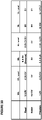
- Table No. 1 depicts typical voltage ranges that can be applied to the terminals of memory cell 210 for performing read, erase, and program operations: Table No. 1: Operation of Flash Memory Cell 210 of Figure 2 WL BL SL Read 2-3V 0.6-2V 0V Erase ⁇ 11-13V 0V 0V Program 1-2V 1-3 ⁇ A 9-10V
- Figure 3 depicts four-gate memory cell 310 comprising source region 14, drain region 16, floating gate 20 over a first portion of channel region 18, a select gate 28 (typically coupled to a word line) over a second portion of the channel region 18, a control gate 22 over the floating gate 20, and an erase gate 30 over the source region 14.
- This configuration is described in U.S. Patent 6,747,310 .
- all gates are non-floating gates except floating gate 20, meaning that they are electrically connected or connectable to a voltage source. Programming is shown by heated electrons from the channel region 18 injecting themselves onto the floating gate 20. Erasing is shown by electrons tunneling from the floating gate 20 to the erase gate 30.
- Table No. 2 depicts typical voltage ranges that can be applied to the terminals of memory cell 310 for performing read, erase, and program operations: Table No. 2: Operation of Flash Memory Cell 310 of Figure 3 WL/SG BL CG EG SL Read 1.0-2V 0.6-2V 0-2.6V 0-2.6V 0V Erase -0.5V/0V 0V 0V/-8V 8-12V 0V Program 1V 1 ⁇ A 8-11V 4.5-9V 4.5-5V
- Figure 4 depicts split gate three-gate memory cell 410.
- Memory cell 410 is identical to the memory cell 310 of Figure 3 except that memory cell 410 does not have a separate control gate.
- the erase operation (erasing through erase gate) and read operation are similar to that of the Figure 3 except there is no control gate bias.
- the programming operation also is done without the control gate bias, hence the program voltage on the source line is higher to compensate for lack of control gate bias.
- Table No. 3 depicts typical voltage ranges that can be applied to the terminals of memory cell 410 for performing read, erase, and program operations: Table No. 3: Operation of Flash Memory Cell 410 of Figure 4 WL/SG BL EG SL Read 0.7-2.2V 0.6-2V 0-2.6V 0V Erase -0.5V/0V 0V 11.5V 0V Program 1V 2-3 ⁇ A 4.5V 7-9V
- Figure 5 depicts stacked gate memory cell 510.
- Memory cell 510 is similar to memory cell 210 of Figure 2 , except floating gate 20 extends over the entire channel region 18, and control gate 22 extends over floating gate 20, separated by an insulating layer.
- the erase, programming, and read operations operate in a similar manner to that described previously for memory cell 210.
- Table No. 4 depicts typical voltage ranges that can be applied to the terminals of memory cell 510 for performing read, erase, and program operations: Table No. 4 Operation of Flash Memory Cell 510 of Figure 5 CG BL SL P-sub Read 2-5V 0.6-2V 0V 0V Erase -8 to -10V/0V FLT FLT 8-10V / 15-20V Program 8-12V 3-5V 0V 0V
- the lines are configured so that each memory cell can be individually programmed, erased, and read without adversely affecting the memory state of other memory cells in the array, as further explained below.
- continuous (analog) programming of the memory cells is provided.
- the memory state (i.e. charge on the floating gate) of each memory cells in the array can be continuously changed from a fully erased state to a fully programmed state, independently and with minimal disturbance of other memory cells.
- the memory state (i.e ., charge on the floating gate) of each memory cell in the array can be continuously changed from a fully programmed state to a fully erased state, and vice-versa, independently and with minimal disturbance of other memory cells.
- the cell storage is analog or at the very least can store one of many discrete values (such as 16 or 64 different values), which allows for very precise and individual tuning of all the cells in the memory array, and which makes the memory array ideal for storing and making fine tuning adjustments to the synapsis weights of the neural network.
- Figure 6 conceptually illustrates a non-limiting example of a neural network utilizing a non-volatile memory array.
- This example uses the non-volatile memory array neural net for a facial recognition application, but any other appropriate application could be implemented using a non-volatile memory array based neural network.
- S0 is the input, which for this example is a 32x32 pixel RGB image with 5 bit precision (i.e. three 32x32 pixel arrays, one for each color R, G and B, each pixel being 5 bit precision).
- the synapses CB1 going from S0 to C1 have both different sets of weights and shared weights, and scan the input image with 3x3 pixel overlapping filters (kernel), shifting the filter by 1 pixel (or more than 1 pixel as dictated by the model).
- values for 9 pixels in a 3x3 portion of the image are provided to the synapses CB1, whereby these 9 input values are multiplied by the appropriate weights and, after summing the outputs of that multiplication, a single output value is determined and provided by a first neuron of CB1 for generating a pixel of one of the layers of feature map C1.
- the 3x3 filter is then shifted one pixel to the right (i.e., adding the column of three pixels on the right, and dropping the column of three pixels on the left), whereby the 9 pixel values in this newly positioned filter are provided to the synapses CB1, whereby they are multiplied by the same weights and a second single output value is determined by the associated neuron.
- This process is continued until the 3x3 filter scans across the entire 32x32 pixel image, for all three colors and for all bits (precision values).
- the process is then repeated using different sets of weights to generate a different feature map of C1, until all the features maps of layer C1 have been calculated.
- each feature map is a two dimensional array, and thus in this example the synapses CB1 constitutes 16 layers of two dimensional arrays (keeping in mind that the neuron layers and arrays referenced herein are logical relationships, not necessarily physical relationships - i.e., the arrays are not necessarily oriented in physical two dimensional arrays).
- Each of the 16 feature maps is generated by one of sixteen different sets of synapse weights applied to the filter scans.
- the C1 feature maps could all be directed to different aspects of the same image feature, such as boundary identification.
- the first map (generated using a first weight set, shared for all scans used to generate this first map) could identify circular edges
- the second map generated using a second weight set different from the first weight set
- An activation function PI (pooling) is applied before going from C1 to S1, which pools values from consecutive, non-overlapping 2x2 regions in each feature map.
- the purpose of the pooling stage is to average out the nearby location (or a max function can also be used), to reduce the dependence of the edge location for example and to reduce the data size before going to the next stage.
- S1 there are 16 15x15 feature maps (i.e., sixteen different arrays of 15x15 pixels each).
- the synapses and associated neurons in CB2 going from S1 to C2 scan maps in S1 with 4x4 filters, with a filter shift of 1 pixel.
- At C2 there are 22 12x12 feature maps.
- An activation function P2 (pooling) is applied before going from C2 to S2, which pools values from consecutive non-overlapping 2x2 regions in each feature map. At S2, there are 22 6x6 feature maps. An activation function is applied at the synapses CB3 going from S2 to C3, where every neuron in C3 connects to every map in S2. At C3, there are 64 neurons. The synapses CB4 going from C3 to the output S3 fully connects S3 to C3. The output at S3 includes 10 neurons, where the highest output neuron determines the class. This output could, for example, be indicative of an identification or classification of the contents of the original image.
- FIG. 7 is a block diagram of the vector-by-matrix multiplication (VMM) array that includes the non-volatile memory cells, and is utilized as the synapses between an input layer and the next layer.
- the VMM 32 includes an array of non-volatile memory cells 33, erase gate and word line gate decoder 34, control gate decoder 35, bit line decoder 36 and source line decoder 37, which decode the inputs for the memory array 33.
- Source line decoder 37 in this example also decodes the output of the memory cell array.
- bit line decoder 36 can decode the output of the memory array.
- the memory array serves two purposes. First, it stores the weights that will be used by the VMM. Second, the memory array effectively multiplies the inputs by the weights stored in the memory array and adds them up per output line (source line or bit line) to produce the output, which will be the input to the next layer or input to the final layer. By performing the multiplication and addition function, the memory array negates the need for separate multiplication and addition logic circuits and is also power efficient due to in-situ memory computation.
- the output of the memory array is supplied to a differential summer (such as summing op-amp) 38, which sums up the outputs of the memory cell array to create a single value for that convolution.
- the differential summer is such as to realize summation of positive weight and negative weight with positive input.
- the summed up output values are then supplied to the activation function circuit 39, which rectifies the output.
- the activation function may include sigmoid, tanh, or ReLU functions.
- the rectified output values become an element of a feature map as the next layer (C1 in the description above for example), and are then applied to the next synapse to produce next feature map layer or final layer.
- the memory array constitutes a plurality of synapses (which receive their inputs from the prior layer of neurons or from an input layer such as an image database), and summing op-amp 38 and activation function circuit 39 constitute a plurality of neurons.
- FIG. 8 is a block diagram of the various levels of VMM.
- the input is converted from digital to analog by digital-to-analog converter 31, and provided to input VMM 32a.
- the output generated by the input VMM 32a is provided as an input to the next VMM (hidden level 1) 32b, which in turn generates an output that is provided as an input to the next VMM (hidden level 2) 32b, and so on.
- the various layers of VMM's 32 function as different layers of synapses and neurons of a convolutional neural network (CNN).
- Each VMM can be a stand-alone non-volatile memory array, or multiple VMMs could utilize different portions of the same non-volatile memory array, or multiple VMMs could utilize overlapping portions of the same non-volatile memory array.
- VMM Vector-by-Matrix Multiplication
- FIG. 9 depicts neuron VMM 900, which is particularly suited for memory cells of the type shown in Figure 2 , and is utilized as the synapses and parts of neurons between an input layer and the next layer.
- VMM 900 comprises a memory array 903 of non-volatile memory cells, reference array 901, and reference array 902.
- Reference arrays 901 and 902 serve to convert current inputs flowing into terminals BLR0-3 into voltage inputs WL0-3.
- Reference arrays 901 and 902 as shown are in the column direction. In general, the reference array direction is orthogonal to the input lines.
- the reference memory cells are diode connected through multiplexors (multiplexor 914, which includes a multiplexor and a cascoding transistor VBLR for biasing the reference bit line) with current inputs flowing into them.
- the reference cells are tuned to target reference levels.
- Memory array 903 serves two purposes. First, it stores the weights that will be used by the VMM 900. Second, memory array 903 effectively multiplies the inputs (current inputs provided in terminals BLR0-3; reference arrays 901 and 902 convert these current inputs into the input voltages to supply to wordlines WL0-3) by the weights stored in the memory array to produce the output, which will be the input to the next layer or input to the final layer. By performing the multiplication function, the memory array negates the need for separate multiplication logic circuits and is also power efficient.
- the voltage inputs are provided on the word lines, and the output emerges on the bit line during a read (inference) operation. The current placed on the bit line performs a summing function of all the currents from the memory cells connected to the bitline.
- Figure 10 depicts operating voltages for VMM 900.
- the columns in the table indicate the voltages placed on word lines for selected cells, word lines for unselected cells, bit lines for selected cells, bit lines for unselected cells, source lines for selected cells, and source lines for unselected cells.
- the rows indicate the operations of read, erase, and program.
- FIG 11 depicts neuron VMM 1100, which is particularly suited for memory cells of the type shown in Figure 2 , and is utilized as the synapses and parts of neurons between an input layer and the next layer.
- VMM 1100 comprises a memory array 1103 of non-volatile memory cells, reference array 1101, and reference array 1102.
- VMM 1100 is similar to VMM 900 except that in VMM 1100 the word lines run in the vertical direction.
- the inputs are provided on the word lines, and the output emerges on the source line during a read operation.
- the current placed on the source line performs a summing function of all the currents from the memory cells connected to the source line.
- Figure 12 depicts operating voltages for VMM 1100.
- the columns in the table indicate the voltages placed on word lines for selected cells, word lines for unselected cells, bit lines for selected cells, bit lines for unselected cells, source lines for selected cells, and source lines for unselected cells.
- the rows indicate the operations of read, erase, and program.
- FIG. 13 depicts neuron VMM 1300, which is particularly suited for memory cells of the type shown in Figure 3 , and is utilized as the synapses and parts of neurons between an input layer and the next layer.
- VMM 1300 comprises a memory array 1301 of non-volatile memory cells, reference array 1302 (providing reference converting input current into input voltage for even rows), and reference array 1303 (providing reference converting input current into input voltage for odd rows).
- VMM 1300 is similar to VMM 900 except VMM 1300 further comprises control line 1306 couples to the control gates of a row of memory cells and control line 1307 coupled to the erase gates of adjoining rows of memory cells.
- the wordlines, control gate lines, and erase gate lines are of the same direction.
- VMM further comprises reference bit line select transistor 1304 (part of mux 1314) that selectively couples a reference bit line to the bit line contact of a selected reference memory cell and switch 1305 (part of mux 1314) that selectively couples a reference bit line to control line 1306 for a particular selected reference memory cell.
- the inputs are provided on the word lines (of memory array 1301), and the output emerges on the bit line, such as bit line 1309, during a read operation.
- the current placed on the bit line performs a summing function of all the currents from the memory cells connected to the bit line.
- Figure 14 depicts operating voltages for VMM 1300.
- the columns in the table indicate the voltages placed on word lines for selected cells, word lines for unselected cells, bit lines for selected cells, bit lines for unselected cells, control gates for selected cells, control gates for unselected cells in the same sector as the selected cells, control gates for unselected cells in a different sector than the selected cells, erase gates for selected cells, erase gates for unselected cells, source lines for selected cells, and source lines for unselected cells.
- the rows indicate the operations of read, erase, and program.
- FIG. 15 depicts neuron VMM 1500, which is particularly suited for memory cells of the type shown in Figure 3 , and is utilized as the synapses and parts of neurons between an input layer and the next layer.
- VMM 1500 is similar to VMM 1100, except in VMM 1500, erase gate lines such as erase gate line 1501 run in a vertical direction.
- the inputs are provided on the word lines, and the output emerges on the source lines.
- the current placed on the bit line performs a summing function of all the currents from the memory cells connected to the bit line.
- Figure 16 depicts operating voltages for VMM 1500.
- the columns in the table indicate the voltages placed on word lines for selected cells, word lines for unselected cells, bit lines for selected cells, bit lines for unselected cells, control gates for selected cells, control gates for unselected cells in the same sector as the selected cells, control gates for unselected cells in a different sector than the selected cells, erase gates for selected cells, erase gates for unselected cells, source lines for selected cells, and source lines for unselected cells.
- the rows indicate the operations of read, erase, and program.
- FIG 17 depicts neuron VMM 1700, which is particularly suited for memory cells of the type shown in Figure 3 , and is utilized as the synapses and parts of neurons between an input layer and the next layer.
- VMM 1700 comprises a memory array 1701 of non-volatile memory cells and reference array 1702 (at the top of the array). Alternatively, another reference array can be placed at the bottom, similar to that of Figure 10 .
- VMM 1700 is similar to previously-described VMMs, except in VMM 1700, control gates line such as control gate line 1703 run in a vertical direction (hence reference array 1702 in the row direction, orthogonal to the input control gate lines), and erase gate lines such as erase gate line 1704 run in a horizontal direction.
- the inputs are provided on the control gate lines, and the output emerges on the source lines. In one embodiment only even rows are used, and in another embodiment, only odd rows are used.
- the current placed on the source line performs a summing function of all the currents from the memory cells connected to the source line.
- the flash cells are preferably configured to operate in sub-threshold region.
- Vg k * Vt * log Ids / wp * Io
- a wordline or control gate can be used as the input for the memory cell for the input voltage.
- a memory cell operating in the linear region can be used to convert linearly an input/output current into an input/output voltage.
- ESF vector matrix multiplier Other embodiments for the ESF vector matrix multiplier are as described in U.S. Patent Application No. Application No. 15/826,345 .
- a sourceline or a bitline can be used as the neuron output (current summation output).
- Figure 18 depicts analog neuromorphic memory system 1800, which comprises system controller 1801, analog neuromorphic memory engine 1802, and analog neuromorphic memory engine 1803.
- Analog neuromorphic memory engine 1802 and analog neuromorphic memory engine 1803 each contains a VNM array that are programmed with weights. A portion of the array in the VNM in analog neuromorphic memory engine 1803 is dedicated to a process for determining if data has drifted.
- Figure 19 depicts method 1900 for refreshing data in a VNM.
- a set of flash memory cells are sampled (sample selection in step 1901).
- a sample is analyzed for each possible level (N values) stored by the flash memory cells (L0, ... LN-1), and a difference (DRx) is calculated between each pair of adjacent levels (step 1902).
- the difference (DRx) is compared to the target (ideal) (DRx_target) (step 1903). If any of the differences (DRx) exceeds the target, then a refresh flag is set (step 1904).
- a restore data process than occurs step 1905). This step can be done by on-chip controller or by an off-chip controller.
- a re-tuning step (e.g., re-programming) is tailored for each level.
- a re-tuning step e.g., re-programming
- a delta re-tuning is applied for that level.
- a look up table Icell vs. I-tuned target
- a tuning algorithm iterative verify and program
- the restore is also done for sampled data retention cells.
- Figure 20 depicts another method 2000 for refreshing data in a VNM.
- a set of exemplary flash memory cells are sampled (step 2001).
- a sample is analyzed for each possible level (N values) stored by the flash memory cells (L0, ... LN-1), and a difference (DRx) is calculated between each pair of adjacent levels (step 2002).
- the difference (DRx) is compared to the target (ideal) (DRx_target) (step 2003). If any of the differences (DRx) exceeds the target, then a refresh flag is set (step 2004).
- the restore can be done by an on-chip or off-chip controller.
- a re-tuning step e.g., re-programming
- a delta re-tuning is applied for that level by a fine increment restore algorithm.
- a look up table Icell vs. I-tuned target
- a fine tuning algorithm fine step iterative verify and program
- the data restore can be done by re-programming the whole VMM arrays by transferring all the weights from training to the VMM arrays.
- step 2008 If that is never reached, then the cell is deemed bad (step 2008).
- a redundancy array sector is then used replace the bad array sector (step 2009). If the number of redundancy cells used in this manner exceeds a threshold (step 2010), then the entire sector is deemed bad (step 2011).
- fast cells are cells which can lose charge from their floating gates during a program operation relatively quickly compared to an average cell, as such fast cells are more prone to data drift over time.
- fast cells can be identified, with reference to graph 2100, as those that obtain a high current level, Ircell, with relatively few programming attempts (counts).
- Ircell current level
- FIG 22 with reference to graph 2200, it is understood that a fast cell is likely to have a high Ir operating range than normal cells.
- Figure 22 shows exemplary cells used to data retention (drift) monitor. Cells that exceed the minimum and maximum range are used for monitor purpose. This is used to create monitor cells with stress condition worse than normal cells .
- Figure 23 depicts a data drift detection scheme.
- a certain current level be between target1 and target2. If the sensed current is between those targets, then no refresh is needed, meaning the drift is acceptable for system performance. However, if the sensed current is outside of the range between target1 and target 2, then a data refresh (restore) process is performed.
- Figure 24 depicts an embodiment of a data drift detector.
- Data drift detector 2400 receives current 2402 (which can be either a sensed current level through a selected cell or a difference between such currents) and a reference current 2401 in comparator 2403, which outputs a value indicating whether current 2402 exceeds reference current 2401 or not.
- Data drift detector 2400 compares current drawn by a selected cell with a target current based on the value that is intended to have been stored in the selected cell.
- Figure 25 depicts another embodiment of a data drift detector.
- Data drift detector 2500 comprises sample-and-hold capacitors 2501 and 2504, switches 2502 and 2505, current source 2506 (which can be either a sensed current level through a selected cell or a difference between such currents), reference current 2503, and comparator 2507.
- the two current sources are sampled by the capacitors through a determined ramping time period and held, and those sampled values are then compared by comparator 2507.
- data drift detector 2500 compares a sampled current drawn by a selected cell with a sampled target current based on the value that is intended to have been stored in the selected cell.
- the sampling period of data drift detector 2500 can be selected based on an understanding of how much time is likely to elapse before significant data drift occurs. This can result in less power consumption compared to the data drift detector 2400.
- Figure 27 depicts another embodiment of a data drift detector.
- Data drift detector 2700 comprises selected memory cell 2701, current source 2702, reference voltage 2703, and comparator 2704.
- the memory cell 2701 is configured in a source-follower operation mode.
- the reference voltage can be generated from a reference memory cell.
- the term “adjacent” includes “directly adjacent” (no intermediate materials, elements or space disposed therebetween) and “indirectly adjacent” (intermediate materials, elements or space disposed there between), “mounted to” includes “directly mounted to” (no intermediate materials, elements or space disposed there between) and “indirectly mounted to” (intermediate materials, elements or spaced disposed there between), and “electrically coupled” includes “directly electrically coupled to” (no intermediate materials or elements there between that electrically connect the elements together) and “indirectly electrically coupled to” (intermediate materials or elements there between that electrically connect the elements together).
- forming an element "over a substrate” can include forming the element directly on the substrate with no intermediate materials/elements therebetween, as well as forming the element indirectly on the substrate with one or more intermediate materials/elements there between.
Landscapes
- Engineering & Computer Science (AREA)
- Physics & Mathematics (AREA)
- Theoretical Computer Science (AREA)
- Health & Medical Sciences (AREA)
- Life Sciences & Earth Sciences (AREA)
- Biomedical Technology (AREA)
- General Health & Medical Sciences (AREA)
- Molecular Biology (AREA)
- Microelectronics & Electronic Packaging (AREA)
- Biophysics (AREA)
- Computer Hardware Design (AREA)
- Evolutionary Computation (AREA)
- Data Mining & Analysis (AREA)
- Artificial Intelligence (AREA)
- Computing Systems (AREA)
- General Engineering & Computer Science (AREA)
- General Physics & Mathematics (AREA)
- Mathematical Physics (AREA)
- Software Systems (AREA)
- Computational Linguistics (AREA)
- Neurology (AREA)
- Non-Volatile Memory (AREA)
- Read Only Memory (AREA)
Applications Claiming Priority (3)
| Application Number | Priority Date | Filing Date | Title |
|---|---|---|---|
| US201862642867P | 2018-03-14 | 2018-03-14 | |
| US15/990,220 US10446246B2 (en) | 2018-03-14 | 2018-05-25 | Method and apparatus for data refresh for analog non-volatile memory in deep learning neural network |
| PCT/US2019/013871 WO2019177687A1 (en) | 2018-03-14 | 2019-01-16 | Method and apparatus for data refresh for analog non-volatile memory in deep learning neural network |
Publications (3)
| Publication Number | Publication Date |
|---|---|
| EP3766071A1 EP3766071A1 (en) | 2021-01-20 |
| EP3766071A4 EP3766071A4 (en) | 2021-09-29 |
| EP3766071B1 true EP3766071B1 (en) | 2022-11-23 |
Family
ID=67906045
Family Applications (1)
| Application Number | Title | Priority Date | Filing Date |
|---|---|---|---|
| EP19767098.7A Active EP3766071B1 (en) | 2018-03-14 | 2019-01-16 | Method for data refresh for analog non-volatile memory in deep learning neural network |
Country Status (7)
| Country | Link |
|---|---|
| US (3) | US10446246B2 (zh) |
| EP (1) | EP3766071B1 (zh) |
| JP (1) | JP7153737B2 (zh) |
| KR (1) | KR102430151B1 (zh) |
| CN (1) | CN111837189A (zh) |
| TW (3) | TWI755339B (zh) |
| WO (1) | WO2019177687A1 (zh) |
Families Citing this family (13)
| Publication number | Priority date | Publication date | Assignee | Title |
|---|---|---|---|---|
| US11461621B2 (en) * | 2018-06-26 | 2022-10-04 | Vishal Sarin | Methods and systems of implementing positive and negative neurons in a neural array-based flash memory |
| CN110797067B (zh) * | 2019-10-21 | 2021-10-22 | 上海闪易半导体有限公司 | 存储阵列模块及其控制方法、装置、模组 |
| CN111222626B (zh) * | 2019-11-07 | 2021-08-10 | 恒烁半导体(合肥)股份有限公司 | 一种基于NOR Flash模块的神经网络的数据切分运算方法 |
| US11636322B2 (en) | 2020-01-03 | 2023-04-25 | Silicon Storage Technology, Inc. | Precise data tuning method and apparatus for analog neural memory in an artificial neural network |
| DE112021003900T5 (de) * | 2020-07-17 | 2023-07-13 | Semiconductor Energy Laboratory Co., Ltd. | Halbleitervorrichtung und elektronisches Gerät |
| CN112053726B (zh) * | 2020-09-09 | 2022-04-12 | 哈尔滨工业大学 | 一种基于Er态阈值电压分布的闪存误擦除数据恢复方法 |
| US11626168B2 (en) | 2021-03-10 | 2023-04-11 | Samsung Electronics Co.. Ltd. | De-noising using multiple threshold-expert machine learning models |
| KR102612011B1 (ko) * | 2021-03-24 | 2023-12-07 | 광운대학교 산학협력단 | 인공 신경망 소자 및 이의 동작 방법 |
| US12014768B2 (en) | 2021-07-29 | 2024-06-18 | Taiwan Semiconductor Manufacturing Company, Ltd. | DRAM computation circuit and method |
| EP4385015A1 (en) * | 2021-11-12 | 2024-06-19 | Silicon Storage Technology Inc. | Determination of a bias voltage to apply to one or more memory cells in a neural network |
| US11942144B2 (en) | 2022-01-24 | 2024-03-26 | Stmicroelectronics S.R.L. | In-memory computation system with drift compensation circuit |
| CN115148248B (zh) * | 2022-09-06 | 2022-11-08 | 北京奎芯集成电路设计有限公司 | 基于深度学习的dram刷新方法和装置 |
| KR102525664B1 (ko) * | 2022-09-15 | 2023-04-25 | 전남대학교산학협력단 | 메모리 반도체 최적의 예비자원 수 예측 방법 및 장치 |
Family Cites Families (40)
| Publication number | Priority date | Publication date | Assignee | Title |
|---|---|---|---|---|
| US5029130A (en) | 1990-01-22 | 1991-07-02 | Silicon Storage Technology, Inc. | Single transistor non-valatile electrically alterable semiconductor memory device |
| US5239505A (en) * | 1990-12-28 | 1993-08-24 | Intel Corporation | Floating gate non-volatile memory with blocks and memory refresh |
| US5479170A (en) * | 1992-10-16 | 1995-12-26 | California Institute Of Technology | Method and apparatus for long-term multi-valued storage in dynamic analog memory |
| US5909449A (en) * | 1997-09-08 | 1999-06-01 | Invox Technology | Multibit-per-cell non-volatile memory with error detection and correction |
| US6493270B2 (en) * | 1999-07-01 | 2002-12-10 | Micron Technology, Inc. | Leakage detection in programming algorithm for a flash memory device |
| WO2001015172A2 (en) * | 1999-08-23 | 2001-03-01 | Micron Technology, Inc. | Flash memory with externally triggered detection and repair of leaky cells |
| JP2001076496A (ja) * | 1999-09-02 | 2001-03-23 | Fujitsu Ltd | 不揮発性メモリのデータ化け防止回路およびその方法 |
| US6396744B1 (en) * | 2000-04-25 | 2002-05-28 | Multi Level Memory Technology | Flash memory with dynamic refresh |
| JP2002230984A (ja) | 2001-02-05 | 2002-08-16 | Fujitsu Ltd | 不揮発性半導体記憶装置 |
| TW559814B (en) * | 2001-05-31 | 2003-11-01 | Semiconductor Energy Lab | Nonvolatile memory and method of driving the same |
| US6747310B2 (en) | 2002-10-07 | 2004-06-08 | Actrans System Inc. | Flash memory cells with separated self-aligned select and erase gates, and process of fabrication |
| JP4104151B2 (ja) | 2003-04-28 | 2008-06-18 | スパンション エルエルシー | 不揮発性半導体記憶装置及び不揮発性半導体記憶装置のプログラム方法 |
| CN1710661A (zh) * | 2004-06-16 | 2005-12-21 | 皇家飞利浦电子股份有限公司 | 一种确定光盘读取信号质量的方法及装置 |
| JP2008525924A (ja) * | 2004-10-21 | 2008-07-17 | エヌエックスピー ビー ヴィ | 記憶装置及びリフレッシュ機構に基づく平均しきい値を発生する方法 |
| US7551503B2 (en) * | 2005-06-24 | 2009-06-23 | Macronix International Co., Ltd. | Method for refreshing a flash memory |
| US7558149B2 (en) * | 2006-01-24 | 2009-07-07 | Macronix International Co., Ltd. | Method and apparatus to control sensing time for nonvolatile memory |
| EP1843356A1 (en) * | 2006-04-03 | 2007-10-10 | STMicroelectronics S.r.l. | Method and system for refreshing a memory device during reading thereof |
| US7639542B2 (en) | 2006-05-15 | 2009-12-29 | Apple Inc. | Maintenance operations for multi-level data storage cells |
| US7869275B2 (en) * | 2006-10-07 | 2011-01-11 | Active-Semi, Inc. | Memory structure capable of bit-wise write or overwrite |
| WO2009039169A1 (en) * | 2007-09-17 | 2009-03-26 | Innovative Silicon S.A. | Refreshing data of memory cells with electrically floating body transistors |
| US8000141B1 (en) * | 2007-10-19 | 2011-08-16 | Anobit Technologies Ltd. | Compensation for voltage drifts in analog memory cells |
| JP2009140564A (ja) | 2007-12-06 | 2009-06-25 | Toshiba Corp | Nand型フラッシュメモリおよびメモリシステム |
| US7859932B2 (en) * | 2008-12-18 | 2010-12-28 | Sandisk Corporation | Data refresh for non-volatile storage |
| US8032804B2 (en) * | 2009-01-12 | 2011-10-04 | Micron Technology, Inc. | Systems and methods for monitoring a memory system |
| WO2011067795A1 (en) * | 2009-12-02 | 2011-06-09 | Ferdinando Bedeschi | Refresh architecture and algorithm for non-volatile memories |
| US8649215B2 (en) * | 2010-12-22 | 2014-02-11 | HGST Netherlands B.V. | Data management in flash memory using probability of charge disturbances |
| US9286205B2 (en) * | 2011-12-20 | 2016-03-15 | Intel Corporation | Apparatus and method for phase change memory drift management |
| US9645177B2 (en) * | 2012-05-04 | 2017-05-09 | Seagate Technology Llc | Retention-drift-history-based non-volatile memory read threshold optimization |
| US9224089B2 (en) * | 2012-08-07 | 2015-12-29 | Qualcomm Incorporated | Method and apparatus for adaptive bit-allocation in neural systems |
| US9378830B2 (en) * | 2013-07-16 | 2016-06-28 | Seagate Technology Llc | Partial reprogramming of solid-state non-volatile memory cells |
| US9564219B2 (en) * | 2015-04-08 | 2017-02-07 | Sandisk Technologies Llc | Current based detection and recording of memory hole-interconnect spacing defects |
| US9563505B2 (en) * | 2015-05-26 | 2017-02-07 | Winbond Electronics Corp. | Methods and systems for nonvolatile memory data management |
| US9836349B2 (en) * | 2015-05-29 | 2017-12-05 | Winbond Electronics Corp. | Methods and systems for detecting and correcting errors in nonvolatile memory |
| US10121553B2 (en) * | 2015-09-30 | 2018-11-06 | Sunrise Memory Corporation | Capacitive-coupled non-volatile thin-film transistor NOR strings in three-dimensional arrays |
| KR102491133B1 (ko) * | 2016-03-21 | 2023-01-25 | 에스케이하이닉스 주식회사 | 메모리 장치 및 이의 동작 방법 |
| US20170330109A1 (en) * | 2016-05-16 | 2017-11-16 | Purepredictive, Inc. | Predictive drift detection and correction |
| JP6833873B2 (ja) | 2016-05-17 | 2021-02-24 | シリコン ストーリッジ テクノロージー インコーポレイテッドSilicon Storage Technology, Inc. | 不揮発性メモリアレイを使用したディープラーニングニューラルネットワーク分類器 |
| EP3367385B1 (en) * | 2017-02-28 | 2020-07-08 | ams AG | Memory arrangement and method for operating a memory arrangement |
| KR102415867B1 (ko) * | 2017-11-29 | 2022-07-04 | 에스케이하이닉스 주식회사 | 메모리 셀의 결함을 제거하기 위한 메모리 시스템 및 그의 동작 방법 |
| US10748630B2 (en) * | 2017-11-29 | 2020-08-18 | Silicon Storage Technology, Inc. | High precision and highly efficient tuning mechanisms and algorithms for analog neuromorphic memory in artificial neural networks |
-
2018
- 2018-05-25 US US15/990,220 patent/US10446246B2/en active Active
-
2019
- 2019-01-16 WO PCT/US2019/013871 patent/WO2019177687A1/en unknown
- 2019-01-16 EP EP19767098.7A patent/EP3766071B1/en active Active
- 2019-01-16 KR KR1020207026690A patent/KR102430151B1/ko active IP Right Grant
- 2019-01-16 JP JP2020548669A patent/JP7153737B2/ja active Active
- 2019-01-16 CN CN201980018504.7A patent/CN111837189A/zh active Pending
- 2019-02-18 TW TW110123297A patent/TWI755339B/zh active
- 2019-02-18 TW TW109116174A patent/TWI733451B/zh active
- 2019-02-18 TW TW108105316A patent/TWI696128B/zh active
- 2019-05-16 US US16/414,714 patent/US10607710B2/en active Active
- 2019-10-02 US US16/590,798 patent/US10861568B2/en active Active
Also Published As
| Publication number | Publication date |
|---|---|
| TWI755339B (zh) | 2022-02-11 |
| JP2021517704A (ja) | 2021-07-26 |
| TWI733451B (zh) | 2021-07-11 |
| EP3766071A1 (en) | 2021-01-20 |
| KR20220114095A (ko) | 2022-08-17 |
| US20200035310A1 (en) | 2020-01-30 |
| US10607710B2 (en) | 2020-03-31 |
| TW201939362A (zh) | 2019-10-01 |
| JP7153737B2 (ja) | 2022-10-14 |
| WO2019177687A1 (en) | 2019-09-19 |
| TW202044127A (zh) | 2020-12-01 |
| KR20200121347A (ko) | 2020-10-23 |
| KR102430151B1 (ko) | 2022-08-08 |
| US20190287631A1 (en) | 2019-09-19 |
| TW202137074A (zh) | 2021-10-01 |
| EP3766071A4 (en) | 2021-09-29 |
| US10446246B2 (en) | 2019-10-15 |
| CN111837189A (zh) | 2020-10-27 |
| US10861568B2 (en) | 2020-12-08 |
| US20190341118A1 (en) | 2019-11-07 |
| TWI696128B (zh) | 2020-06-11 |
Similar Documents
| Publication | Publication Date | Title |
|---|---|---|
| EP3766071B1 (en) | Method for data refresh for analog non-volatile memory in deep learning neural network | |
| KR102654503B1 (ko) | 딥 러닝 인공 신경망에서의 아날로그 신경 메모리용 고전압 생성을 위한 방법 및 장치 | |
| EP3766178B1 (en) | Decoders for analog neural memory in deep learning artificial neural network | |
| EP4202769A1 (en) | Analog neural memory system for deep learning neural network comprising multiple vector-by-matrix multiplication arrays and shared components | |
| EP4138079B1 (en) | Temperature and leakage compensation for memory cells in an analog memory system for use in a deep learning neural network | |
| EP3821375B1 (en) | Compensation for reference transistors and memory cells in analog neuro memory in deep learning artificial neural network | |
| EP4407874A2 (en) | Analog neural memory array in artificial neural network with substantially constant array source impedance with adaptive weight mapping and distributed power | |
| US20220067499A1 (en) | Concurrent write and verify operations in an analog neural memory | |
| US20240112736A1 (en) | Adaptive bias decoder for non-volatile memory system | |
| CN112368716A (zh) | 对深度学习人工神经网络中的模拟神经存储器中包含故障存储器单元的行或列的冗余存储器访问 | |
| US20210350217A1 (en) | Analog neural memory array in artificial neural network with source line pulldown mechanism | |
| KR102716617B1 (ko) | 심층 학습 신경망에서 아날로그 비휘발성 메모리를 위한 데이터 리프레쉬 방법 및 장치 | |
| US20220374696A1 (en) | Split array architecture for analog neural memory in a deep learning artificial neural network | |
| US11989440B2 (en) | Hybrid memory system configurable to store neural memory weight data in analog form or digital form | |
| US20230244903A1 (en) | Artificial neural network comprising an analog array and a digital array | |
| WO2024162979A1 (en) | Current-to-voltage converter comprising common mode circuit |
Legal Events
| Date | Code | Title | Description |
|---|---|---|---|
| STAA | Information on the status of an ep patent application or granted ep patent |
Free format text: STATUS: THE INTERNATIONAL PUBLICATION HAS BEEN MADE |
|
| PUAI | Public reference made under article 153(3) epc to a published international application that has entered the european phase |
Free format text: ORIGINAL CODE: 0009012 |
|
| STAA | Information on the status of an ep patent application or granted ep patent |
Free format text: STATUS: REQUEST FOR EXAMINATION WAS MADE |
|
| 17P | Request for examination filed |
Effective date: 20201014 |
|
| AK | Designated contracting states |
Kind code of ref document: A1 Designated state(s): AL AT BE BG CH CY CZ DE DK EE ES FI FR GB GR HR HU IE IS IT LI LT LU LV MC MK MT NL NO PL PT RO RS SE SI SK SM TR |
|
| AX | Request for extension of the european patent |
Extension state: BA ME |
|
| DAV | Request for validation of the european patent (deleted) | ||
| DAX | Request for extension of the european patent (deleted) | ||
| A4 | Supplementary search report drawn up and despatched |
Effective date: 20210831 |
|
| RIC1 | Information provided on ipc code assigned before grant |
Ipc: G06N 3/08 20060101ALN20210825BHEP Ipc: G06N 3/063 20060101ALN20210825BHEP Ipc: G06N 3/04 20060101ALN20210825BHEP Ipc: G11C 29/52 20060101ALN20210825BHEP Ipc: G11C 29/44 20060101ALN20210825BHEP Ipc: G11C 16/26 20060101ALN20210825BHEP Ipc: G11C 16/16 20060101ALN20210825BHEP Ipc: G11C 16/08 20060101ALN20210825BHEP Ipc: G11C 16/04 20060101ALN20210825BHEP Ipc: G11C 7/10 20060101ALN20210825BHEP Ipc: G11C 27/00 20060101ALI20210825BHEP Ipc: G11C 16/28 20060101ALI20210825BHEP Ipc: G11C 11/56 20060101ALI20210825BHEP Ipc: G11C 11/54 20060101ALI20210825BHEP Ipc: G11C 7/16 20060101ALI20210825BHEP Ipc: G11C 16/34 20060101AFI20210825BHEP |
|
| REG | Reference to a national code |
Ref country code: DE Ref legal event code: R079 Ref document number: 602019022273 Country of ref document: DE Free format text: PREVIOUS MAIN CLASS: G11C0016260000 Ipc: G11C0016340000 |
|
| GRAP | Despatch of communication of intention to grant a patent |
Free format text: ORIGINAL CODE: EPIDOSNIGR1 |
|
| STAA | Information on the status of an ep patent application or granted ep patent |
Free format text: STATUS: GRANT OF PATENT IS INTENDED |
|
| RIC1 | Information provided on ipc code assigned before grant |
Ipc: G06N 3/08 20060101ALN20220523BHEP Ipc: G06N 3/063 20060101ALN20220523BHEP Ipc: G06N 3/04 20060101ALN20220523BHEP Ipc: G11C 29/52 20060101ALN20220523BHEP Ipc: G11C 29/44 20060101ALN20220523BHEP Ipc: G11C 16/26 20060101ALN20220523BHEP Ipc: G11C 16/16 20060101ALN20220523BHEP Ipc: G11C 16/08 20060101ALN20220523BHEP Ipc: G11C 16/04 20060101ALN20220523BHEP Ipc: G11C 7/10 20060101ALN20220523BHEP Ipc: G11C 27/00 20060101ALI20220523BHEP Ipc: G11C 16/28 20060101ALI20220523BHEP Ipc: G11C 11/56 20060101ALI20220523BHEP Ipc: G11C 11/54 20060101ALI20220523BHEP Ipc: G11C 7/16 20060101ALI20220523BHEP Ipc: G11C 16/34 20060101AFI20220523BHEP |
|
| RIC1 | Information provided on ipc code assigned before grant |
Ipc: G06N 3/08 20060101ALN20220530BHEP Ipc: G06N 3/063 20060101ALN20220530BHEP Ipc: G06N 3/04 20060101ALN20220530BHEP Ipc: G11C 29/52 20060101ALN20220530BHEP Ipc: G11C 29/44 20060101ALN20220530BHEP Ipc: G11C 16/26 20060101ALN20220530BHEP Ipc: G11C 16/16 20060101ALN20220530BHEP Ipc: G11C 16/08 20060101ALN20220530BHEP Ipc: G11C 16/04 20060101ALN20220530BHEP Ipc: G11C 7/10 20060101ALN20220530BHEP Ipc: G11C 27/00 20060101ALI20220530BHEP Ipc: G11C 16/28 20060101ALI20220530BHEP Ipc: G11C 11/56 20060101ALI20220530BHEP Ipc: G11C 11/54 20060101ALI20220530BHEP Ipc: G11C 7/16 20060101ALI20220530BHEP Ipc: G11C 16/34 20060101AFI20220530BHEP |
|
| INTG | Intention to grant announced |
Effective date: 20220623 |
|
| GRAS | Grant fee paid |
Free format text: ORIGINAL CODE: EPIDOSNIGR3 |
|
| GRAA | (expected) grant |
Free format text: ORIGINAL CODE: 0009210 |
|
| STAA | Information on the status of an ep patent application or granted ep patent |
Free format text: STATUS: THE PATENT HAS BEEN GRANTED |
|
| AK | Designated contracting states |
Kind code of ref document: B1 Designated state(s): AL AT BE BG CH CY CZ DE DK EE ES FI FR GB GR HR HU IE IS IT LI LT LU LV MC MK MT NL NO PL PT RO RS SE SI SK SM TR |
|
| REG | Reference to a national code |
Ref country code: GB Ref legal event code: FG4D |
|
| REG | Reference to a national code |
Ref country code: CH Ref legal event code: EP |
|
| REG | Reference to a national code |
Ref country code: DE Ref legal event code: R096 Ref document number: 602019022273 Country of ref document: DE |
|
| REG | Reference to a national code |
Ref country code: AT Ref legal event code: REF Ref document number: 1533650 Country of ref document: AT Kind code of ref document: T Effective date: 20221215 |
|
| REG | Reference to a national code |
Ref country code: IE Ref legal event code: FG4D |
|
| REG | Reference to a national code |
Ref country code: NL Ref legal event code: FP |
|
| REG | Reference to a national code |
Ref country code: LT Ref legal event code: MG9D |
|
| REG | Reference to a national code |
Ref country code: AT Ref legal event code: MK05 Ref document number: 1533650 Country of ref document: AT Kind code of ref document: T Effective date: 20221123 |
|
| PG25 | Lapsed in a contracting state [announced via postgrant information from national office to epo] |
Ref country code: SE Free format text: LAPSE BECAUSE OF FAILURE TO SUBMIT A TRANSLATION OF THE DESCRIPTION OR TO PAY THE FEE WITHIN THE PRESCRIBED TIME-LIMIT Effective date: 20221123 Ref country code: PT Free format text: LAPSE BECAUSE OF FAILURE TO SUBMIT A TRANSLATION OF THE DESCRIPTION OR TO PAY THE FEE WITHIN THE PRESCRIBED TIME-LIMIT Effective date: 20230323 Ref country code: NO Free format text: LAPSE BECAUSE OF FAILURE TO SUBMIT A TRANSLATION OF THE DESCRIPTION OR TO PAY THE FEE WITHIN THE PRESCRIBED TIME-LIMIT Effective date: 20230223 Ref country code: LT Free format text: LAPSE BECAUSE OF FAILURE TO SUBMIT A TRANSLATION OF THE DESCRIPTION OR TO PAY THE FEE WITHIN THE PRESCRIBED TIME-LIMIT Effective date: 20221123 Ref country code: FI Free format text: LAPSE BECAUSE OF FAILURE TO SUBMIT A TRANSLATION OF THE DESCRIPTION OR TO PAY THE FEE WITHIN THE PRESCRIBED TIME-LIMIT Effective date: 20221123 Ref country code: ES Free format text: LAPSE BECAUSE OF FAILURE TO SUBMIT A TRANSLATION OF THE DESCRIPTION OR TO PAY THE FEE WITHIN THE PRESCRIBED TIME-LIMIT Effective date: 20221123 Ref country code: AT Free format text: LAPSE BECAUSE OF FAILURE TO SUBMIT A TRANSLATION OF THE DESCRIPTION OR TO PAY THE FEE WITHIN THE PRESCRIBED TIME-LIMIT Effective date: 20221123 |
|
| PG25 | Lapsed in a contracting state [announced via postgrant information from national office to epo] |
Ref country code: RS Free format text: LAPSE BECAUSE OF FAILURE TO SUBMIT A TRANSLATION OF THE DESCRIPTION OR TO PAY THE FEE WITHIN THE PRESCRIBED TIME-LIMIT Effective date: 20221123 Ref country code: PL Free format text: LAPSE BECAUSE OF FAILURE TO SUBMIT A TRANSLATION OF THE DESCRIPTION OR TO PAY THE FEE WITHIN THE PRESCRIBED TIME-LIMIT Effective date: 20221123 Ref country code: LV Free format text: LAPSE BECAUSE OF FAILURE TO SUBMIT A TRANSLATION OF THE DESCRIPTION OR TO PAY THE FEE WITHIN THE PRESCRIBED TIME-LIMIT Effective date: 20221123 Ref country code: IS Free format text: LAPSE BECAUSE OF FAILURE TO SUBMIT A TRANSLATION OF THE DESCRIPTION OR TO PAY THE FEE WITHIN THE PRESCRIBED TIME-LIMIT Effective date: 20230323 Ref country code: HR Free format text: LAPSE BECAUSE OF FAILURE TO SUBMIT A TRANSLATION OF THE DESCRIPTION OR TO PAY THE FEE WITHIN THE PRESCRIBED TIME-LIMIT Effective date: 20221123 Ref country code: GR Free format text: LAPSE BECAUSE OF FAILURE TO SUBMIT A TRANSLATION OF THE DESCRIPTION OR TO PAY THE FEE WITHIN THE PRESCRIBED TIME-LIMIT Effective date: 20230224 |
|
| P01 | Opt-out of the competence of the unified patent court (upc) registered |
Effective date: 20230528 |
|
| PG25 | Lapsed in a contracting state [announced via postgrant information from national office to epo] |
Ref country code: SM Free format text: LAPSE BECAUSE OF FAILURE TO SUBMIT A TRANSLATION OF THE DESCRIPTION OR TO PAY THE FEE WITHIN THE PRESCRIBED TIME-LIMIT Effective date: 20221123 Ref country code: RO Free format text: LAPSE BECAUSE OF FAILURE TO SUBMIT A TRANSLATION OF THE DESCRIPTION OR TO PAY THE FEE WITHIN THE PRESCRIBED TIME-LIMIT Effective date: 20221123 Ref country code: EE Free format text: LAPSE BECAUSE OF FAILURE TO SUBMIT A TRANSLATION OF THE DESCRIPTION OR TO PAY THE FEE WITHIN THE PRESCRIBED TIME-LIMIT Effective date: 20221123 Ref country code: DK Free format text: LAPSE BECAUSE OF FAILURE TO SUBMIT A TRANSLATION OF THE DESCRIPTION OR TO PAY THE FEE WITHIN THE PRESCRIBED TIME-LIMIT Effective date: 20221123 Ref country code: CZ Free format text: LAPSE BECAUSE OF FAILURE TO SUBMIT A TRANSLATION OF THE DESCRIPTION OR TO PAY THE FEE WITHIN THE PRESCRIBED TIME-LIMIT Effective date: 20221123 |
|
| REG | Reference to a national code |
Ref country code: DE Ref legal event code: R097 Ref document number: 602019022273 Country of ref document: DE |
|
| PG25 | Lapsed in a contracting state [announced via postgrant information from national office to epo] |
Ref country code: SK Free format text: LAPSE BECAUSE OF FAILURE TO SUBMIT A TRANSLATION OF THE DESCRIPTION OR TO PAY THE FEE WITHIN THE PRESCRIBED TIME-LIMIT Effective date: 20221123 Ref country code: AL Free format text: LAPSE BECAUSE OF FAILURE TO SUBMIT A TRANSLATION OF THE DESCRIPTION OR TO PAY THE FEE WITHIN THE PRESCRIBED TIME-LIMIT Effective date: 20221123 |
|
| REG | Reference to a national code |
Ref country code: CH Ref legal event code: PL |
|
| PG25 | Lapsed in a contracting state [announced via postgrant information from national office to epo] |
Ref country code: LU Free format text: LAPSE BECAUSE OF NON-PAYMENT OF DUE FEES Effective date: 20230116 |
|
| PLBE | No opposition filed within time limit |
Free format text: ORIGINAL CODE: 0009261 |
|
| STAA | Information on the status of an ep patent application or granted ep patent |
Free format text: STATUS: NO OPPOSITION FILED WITHIN TIME LIMIT |
|
| REG | Reference to a national code |
Ref country code: BE Ref legal event code: MM Effective date: 20230131 |
|
| GBPC | Gb: european patent ceased through non-payment of renewal fee |
Effective date: 20230223 |
|
| PG25 | Lapsed in a contracting state [announced via postgrant information from national office to epo] |
Ref country code: LI Free format text: LAPSE BECAUSE OF NON-PAYMENT OF DUE FEES Effective date: 20230131 Ref country code: CH Free format text: LAPSE BECAUSE OF NON-PAYMENT OF DUE FEES Effective date: 20230131 |
|
| 26N | No opposition filed |
Effective date: 20230824 |
|
| PG25 | Lapsed in a contracting state [announced via postgrant information from national office to epo] |
Ref country code: SI Free format text: LAPSE BECAUSE OF FAILURE TO SUBMIT A TRANSLATION OF THE DESCRIPTION OR TO PAY THE FEE WITHIN THE PRESCRIBED TIME-LIMIT Effective date: 20221123 Ref country code: BE Free format text: LAPSE BECAUSE OF NON-PAYMENT OF DUE FEES Effective date: 20230131 |
|
| PG25 | Lapsed in a contracting state [announced via postgrant information from national office to epo] |
Ref country code: GB Free format text: LAPSE BECAUSE OF NON-PAYMENT OF DUE FEES Effective date: 20230223 |
|
| PG25 | Lapsed in a contracting state [announced via postgrant information from national office to epo] |
Ref country code: IE Free format text: LAPSE BECAUSE OF NON-PAYMENT OF DUE FEES Effective date: 20230116 Ref country code: GB Free format text: LAPSE BECAUSE OF NON-PAYMENT OF DUE FEES Effective date: 20230223 |
|
| PGFP | Annual fee paid to national office [announced via postgrant information from national office to epo] |
Ref country code: NL Payment date: 20231219 Year of fee payment: 6 Ref country code: FR Payment date: 20231219 Year of fee payment: 6 |
|
| PGFP | Annual fee paid to national office [announced via postgrant information from national office to epo] |
Ref country code: DE Payment date: 20231219 Year of fee payment: 6 |
|
| PG25 | Lapsed in a contracting state [announced via postgrant information from national office to epo] |
Ref country code: IT Free format text: LAPSE BECAUSE OF FAILURE TO SUBMIT A TRANSLATION OF THE DESCRIPTION OR TO PAY THE FEE WITHIN THE PRESCRIBED TIME-LIMIT Effective date: 20221123 |
|
| PG25 | Lapsed in a contracting state [announced via postgrant information from national office to epo] |
Ref country code: MC Free format text: LAPSE BECAUSE OF FAILURE TO SUBMIT A TRANSLATION OF THE DESCRIPTION OR TO PAY THE FEE WITHIN THE PRESCRIBED TIME-LIMIT Effective date: 20221123 |
|
| PG25 | Lapsed in a contracting state [announced via postgrant information from national office to epo] |
Ref country code: MC Free format text: LAPSE BECAUSE OF FAILURE TO SUBMIT A TRANSLATION OF THE DESCRIPTION OR TO PAY THE FEE WITHIN THE PRESCRIBED TIME-LIMIT Effective date: 20221123 |