EP3764002B1 - Refrigeration cycle device - Google Patents
Refrigeration cycle device Download PDFInfo
- Publication number
- EP3764002B1 EP3764002B1 EP19775846.9A EP19775846A EP3764002B1 EP 3764002 B1 EP3764002 B1 EP 3764002B1 EP 19775846 A EP19775846 A EP 19775846A EP 3764002 B1 EP3764002 B1 EP 3764002B1
- Authority
- EP
- European Patent Office
- Prior art keywords
- elastic members
- base
- compressor
- centroid
- disposed
- Prior art date
- Legal status (The legal status is an assumption and is not a legal conclusion. Google has not performed a legal analysis and makes no representation as to the accuracy of the status listed.)
- Active
Links
- 238000005057 refrigeration Methods 0.000 title claims description 48
- 239000003507 refrigerant Substances 0.000 claims description 21
- XLYOFNOQVPJJNP-UHFFFAOYSA-N water Substances O XLYOFNOQVPJJNP-UHFFFAOYSA-N 0.000 description 17
- 239000013598 vector Substances 0.000 description 12
- 238000006073 displacement reaction Methods 0.000 description 6
- 239000000463 material Substances 0.000 description 5
- 239000000470 constituent Substances 0.000 description 3
- JOYRKODLDBILNP-UHFFFAOYSA-N Ethyl urethane Chemical compound CCOC(N)=O JOYRKODLDBILNP-UHFFFAOYSA-N 0.000 description 2
- 230000005540 biological transmission Effects 0.000 description 2
- 238000006243 chemical reaction Methods 0.000 description 2
- 238000001816 cooling Methods 0.000 description 2
- 230000007423 decrease Effects 0.000 description 2
- 238000010438 heat treatment Methods 0.000 description 2
- 238000004378 air conditioning Methods 0.000 description 1
- 230000006835 compression Effects 0.000 description 1
- 238000007906 compression Methods 0.000 description 1
- 230000001419 dependent effect Effects 0.000 description 1
- 238000010586 diagram Methods 0.000 description 1
- 238000005259 measurement Methods 0.000 description 1
- 238000000034 method Methods 0.000 description 1
- 238000005192 partition Methods 0.000 description 1
- 230000001629 suppression Effects 0.000 description 1
Images


Classifications
-
- F—MECHANICAL ENGINEERING; LIGHTING; HEATING; WEAPONS; BLASTING
- F25—REFRIGERATION OR COOLING; COMBINED HEATING AND REFRIGERATION SYSTEMS; HEAT PUMP SYSTEMS; MANUFACTURE OR STORAGE OF ICE; LIQUEFACTION SOLIDIFICATION OF GASES
- F25D—REFRIGERATORS; COLD ROOMS; ICE-BOXES; COOLING OR FREEZING APPARATUS NOT OTHERWISE PROVIDED FOR
- F25D23/00—General constructional features
- F25D23/006—General constructional features for mounting refrigerating machinery components
-
- F—MECHANICAL ENGINEERING; LIGHTING; HEATING; WEAPONS; BLASTING
- F24—HEATING; RANGES; VENTILATING
- F24F—AIR-CONDITIONING; AIR-HUMIDIFICATION; VENTILATION; USE OF AIR CURRENTS FOR SCREENING
- F24F1/00—Room units for air-conditioning, e.g. separate or self-contained units or units receiving primary air from a central station
- F24F1/06—Separate outdoor units, e.g. outdoor unit to be linked to a separate room comprising a compressor and a heat exchanger
- F24F1/08—Compressors specially adapted for separate outdoor units
- F24F1/12—Vibration or noise prevention thereof
-
- F—MECHANICAL ENGINEERING; LIGHTING; HEATING; WEAPONS; BLASTING
- F16—ENGINEERING ELEMENTS AND UNITS; GENERAL MEASURES FOR PRODUCING AND MAINTAINING EFFECTIVE FUNCTIONING OF MACHINES OR INSTALLATIONS; THERMAL INSULATION IN GENERAL
- F16F—SPRINGS; SHOCK-ABSORBERS; MEANS FOR DAMPING VIBRATION
- F16F15/00—Suppression of vibrations in systems; Means or arrangements for avoiding or reducing out-of-balance forces, e.g. due to motion
- F16F15/02—Suppression of vibrations of non-rotating, e.g. reciprocating systems; Suppression of vibrations of rotating systems by use of members not moving with the rotating systems
- F16F15/04—Suppression of vibrations of non-rotating, e.g. reciprocating systems; Suppression of vibrations of rotating systems by use of members not moving with the rotating systems using elastic means
- F16F15/08—Suppression of vibrations of non-rotating, e.g. reciprocating systems; Suppression of vibrations of rotating systems by use of members not moving with the rotating systems using elastic means with rubber springs ; with springs made of rubber and metal
-
- F—MECHANICAL ENGINEERING; LIGHTING; HEATING; WEAPONS; BLASTING
- F25—REFRIGERATION OR COOLING; COMBINED HEATING AND REFRIGERATION SYSTEMS; HEAT PUMP SYSTEMS; MANUFACTURE OR STORAGE OF ICE; LIQUEFACTION SOLIDIFICATION OF GASES
- F25B—REFRIGERATION MACHINES, PLANTS OR SYSTEMS; COMBINED HEATING AND REFRIGERATION SYSTEMS; HEAT PUMP SYSTEMS
- F25B13/00—Compression machines, plants or systems, with reversible cycle
-
- F—MECHANICAL ENGINEERING; LIGHTING; HEATING; WEAPONS; BLASTING
- F25—REFRIGERATION OR COOLING; COMBINED HEATING AND REFRIGERATION SYSTEMS; HEAT PUMP SYSTEMS; MANUFACTURE OR STORAGE OF ICE; LIQUEFACTION SOLIDIFICATION OF GASES
- F25B—REFRIGERATION MACHINES, PLANTS OR SYSTEMS; COMBINED HEATING AND REFRIGERATION SYSTEMS; HEAT PUMP SYSTEMS
- F25B31/00—Compressor arrangements
Description
- The present invention relates to a refrigeration apparatus including a double anti-vibration structure.
- In some usage environments, a heat pump apparatus is required to have low-noise performance. To achieve low-noise performance, it is required to suppress vibration of a compressor constituting a refrigerant circuit of a heat pump from being transmitted to the entirety of the apparatus. For such a purpose,
JP 2005-241197 A JP 2005-241197 A - Further previously known refrigeration cycle apparatuses with a vibration-isolating mounting assembly for mounting the compressor to its associated base pan are derivable from
US 5 306 121 AUS 5 839 295 A - Referring to
Fig. 1 andFig. 4 ofJP 2005-241197 A - The above-mentioned problems are solved by means of a refrigeration cycle apparatus according to one of
independent claims - A refrigeration cycle apparatus according to a first aspect includes a housing, second elastic members, a base, first elastic members, and a compressor. The housing includes a bottom member. The second elastic members are disposed on the bottom member. The base is disposed on the bottom member via the second elastic members. The first elastic members are disposed on the base. The compressor is configured to compress a refrigerant. The compressor is disposed on the base via the first elastic members. A projected position of a centroid of the compressor on the base is represented by a position P. A distance r1 is defined as a distance between the position P and a projected position on the base of a centroid of one of the first elastic members which is closest to the position P. On the base, a circle centered at the position P with a radius of 1.5 times r1 is drawn. The compressor and the second elastic members are disposed such that a projected position Q of an arrangement centroid of the second elastic members on the base is present inside the circle.
- The projected position P of the centroid of the compressor on the base and the projected position Q of the arrangement of the centroid of the second elastic members form a distance PQ.
- In the refrigeration cycle apparatus according to the first aspect, the compressor is disposed close to the arrangement centroid of the second elastic members, and thus, even when the base vibrates, a centrifugal force applied to the compressor is suppressed to be small, a shear force applied to the first elastic members is small, and a stress on a compressor connection pipe is small.
- A refrigeration cycle apparatus according to a second aspect is the refrigeration cycle apparatus according to the first aspect in which the compressor and the second elastic members are disposed such that, when a circle centered at the position P with a radius of r1 is drawn on the base, the projected position Q of the arrangement centroid of the second elastic members on the base is present inside the circle.
- In the refrigeration cycle apparatus according to the second aspect, the compressor is disposed closer to the arrangement centroid of the second elastic members, and thus, even when the base vibrates, the centrifugal force applied to the compressor is suppressed to be smaller, the shear force applied to the first elastic members is smaller, and the stress on the compressor connection pipe is smaller.
- A refrigeration cycle apparatus according to a third aspect includes a housing, second elastic members, a base, first elastic members, and a compressor. The housing includes a bottom member. The second elastic members are disposed on the bottom member. The base is disposed on the bottom member via the second elastic members. The first elastic members are disposed on the base. The compressor is configured to compress a refrigerant. The compressor is disposed on the base via the first elastic members. A projected position of an arrangement centroid of the first elastic members on the base is represented by a position S. A distance r2 is defined as a distance between the position S and a projected position on the base of a centroid of one of the first elastic members which is closest to the position S. On the base, a circle centered at the position S with a radius of 1.5 times r2 is drawn. The first elastic members and the second elastic members are disposed such that a projected position Q of an arrangement centroid of the second elastic members on the base is present inside the circle.
- The projected position S of the centroid of the first elastic members on the base and the projected position Q of the arrangement of the centroid of the second elastic members form a distance SQ.
- In the refrigeration cycle apparatus according to the third aspect, the arrangement centroid of the first elastic members is disposed close to the arrangement centroid of the second elastic members in a top view, and thus, even when the base vibrates, a centrifugal force applied to the compressor is suppressed to be small, a shear force applied to the first elastic members is small, and a stress on a compressor connection pipe is reduced.
- A refrigeration cycle apparatus according to a fourth aspect is the refrigeration cycle apparatus according to the third aspect in which the first elastic members and the second elastic members are disposed such that, when a circle centered at the position S with a radius of r2 is drawn on the base, the projected position Q of the arrangement centroid of the second elastic members on the base is present inside the circle.
- In the refrigeration cycle apparatus according to the fourth aspect, the arrangement centroid of the first elastic members is disposed closer to the arrangement centroid of the second elastic members in a top view, and thus, even when the base vibrates, the centrifugal force applied to the compressor is suppressed to be smaller, the shear force applied to the first elastic members is smaller, and the stress on the compressor connection pipe is further reduced.
- A refrigeration cycle apparatus according to a fifth aspect includes a housing, second elastic members, a base, first elastic members, and a compressor. The housing includes a bottom member. The second elastic members are disposed on the bottom member. The base is disposed on the bottom member via the second elastic members. The first elastic members are disposed on the base. The compressor is configured to compress a refrigerant. The compressor is disposed on the base via the first elastic members. On the base, a distance between a position Q of an arrangement centroid of the second elastic members and a position of a centroid of one of the second elastic members which is farthest from the position Q is represented by r3. On the base, a circle centered at the position Q with a radius of 0.2 times r3 is drawn. The compressor and the second elastic members are disposed such that a projected position P of a centroid of the compressor on the base is presented inside the circle.
- The projected position P of the centroid of the compressor on the base and the projected position Q of the arrangement of the centroid of the second elastic members form a distance PQ.
- In the refrigeration cycle apparatus according to the fifth aspect, the compressor is disposed close to the arrangement centroid of the second elastic members, and thus, even when the base vibrates, a centrifugal force applied to the compressor is suppressed to be small, a shear force applied to the first elastic members is small, and a stress on a compressor connection pipe is reduced.
- A refrigeration cycle apparatus according to a sixth aspect includes a housing, second elastic members, a base, first elastic members, and a compressor. The housing includes a bottom member. The second elastic members are disposed on the bottom member. The base is disposed on the bottom member via the second elastic members. The first elastic members are disposed on the base. The compressor is configured to compress a refrigerant. The compressor is disposed on the base via the first elastic members. On the base, a distance between a position Q of an arrangement centroid of the second elastic members and a position of a centroid of one of the second elastic members which is farthest from the position Q is represented by r3. On the base, a circle centered at the position Q with a radius of 0.2 times r3 is drawn. The first elastic members and the second elastic members are disposed such that a projected position S of an arrangement centroid of the first elastic members on the base is present inside the circle.
- The projected position S of the centroid of the first elastic members on the base and the projected position Q of the arrangement of the centroid of the second elastic members form a distance SQ.
- In the refrigeration cycle apparatus according to the sixth aspect, the arrangement centroid of the first elastic members is disposed close to the arrangement centroid of the second elastic members in a top view, and thus, even when the base vibrates, a centrifugal force applied to the compressor is suppressed to be small, a shear force applied to the first elastic members is small, and a stress on a compressor connection pipe is reduced.
-
- [
Fig. 1] Fig. 1 is a perspective view of an appearance of a refrigeration cycle apparatus of a first embodiment. - [
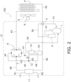
Fig. 2] Fig. 2 is a diagram of a refrigerant circuit of the refrigeration cycle apparatus of the first embodiment. - [
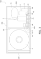
Fig. 3] Fig. 3 is a schematic front view of the refrigeration cycle apparatus of the first embodiment. - [
Fig. 4] Fig. 4 is a top view of the refrigeration cycle apparatus of the first embodiment. - [
Fig. 5] Fig. 5 is a plan of the arrangement of acompressor 1 on abase 21 of the first embodiment. - [
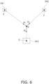
Fig. 6] Fig. 6 describes a method of calculating an arrangement centroid. - A perspective view of an appearance of a
refrigeration cycle apparatus 100 of a first embodiment and a refrigerant circuit are illustrated inFig. 1 andFig. 2 , respectively. Therefrigeration cycle apparatus 100 of the present embodiment is an apparatus that uses a heat pump and that heats and/or cools water. By using heated or cooled water, therefrigeration cycle apparatus 100 can be utilized as a water heater or a water cooler. Alternatively, by using heated or cooled water as a medium, therefrigeration cycle apparatus 100 may constitute an air conditioning apparatus that performs heating and cooling. - As illustrated in
Fig. 2 , the refrigerant circuit of therefrigeration cycle apparatus 100 of the present embodiment includes acompressor 1, anaccumulator 2, a four-way switching valve 3, anair heat exchanger 4, acheck valve 9, afirst expansion valve 7, asecond expansion valve 8, aneconomizer heat exchanger 10, and awater heat exchanger 11. With each device and ajunction 12 connected to each other bypipes 41 to 54, a refrigerant circulates in each device, and a vapor compression refrigeration cycle is performed. Therefrigeration cycle apparatus 100 further includes afan 5 that sends air to theair heat exchanger 4, and afan motor 6 that drives the fan. - When water is to be heated, the
refrigeration cycle apparatus 100 operates as follows. The refrigerant is compressed by thecompressor 1 and sent to thewater heat exchanger 11, which acts as a condenser. The refrigerant is decompressed by, mainly, thefirst expansion valve 7, vaporized by theair heat exchanger 4, which acts as an evaporator, and sent to thecompressor 1 again. Water enters thewater heat exchanger 11 through awater entrance pipe 61, is heated by the refrigerant, and discharged through awater exit pipe 62. Heating and cooling of the water are performed by changing the flow of the refrigerant by switching of the four-way switching valve 3. When the water is to be cooled, thewater heat exchanger 11 acts as a refrigerant evaporator. - An arrangement of devices in the refrigeration cycle apparatus will be described by using the front view in
Fig. 3 and the top view inFig. 4 . For ease of understanding, description of a refrigerant pipe, a control signal line, an electric power supply wire, and the like is omitted, as appropriate, inFig. 3 andFig. 4 . - As illustrated in
Figs. 1 ,3 , and4 , ahousing 20 is constituted by abottom member 20a, atop member 20b, afront member 20c, a right-side member 20d, arear member 20e, and a left-side member 20f. Thehousing 20 covers the outer side of devices constituting the refrigeration cycle. - As illustrated in
Figs. 3 and4 , a space in an inner portion of thehousing 20 is divided by apartition plate 25 into, roughly, a heat exchange chamber on the left side in which theair heat exchanger 4 and thefan 5 are disposed and a machine chamber on the right side in which devices, such as thecompressor 1, are disposed. - As illustrated in
Fig. 3 , in the machine chamber, four secondelastic members 24 are disposed on thebottom member 20a, and thebase 21 is disposed on the secondelastic members 24. The secondelastic member 24 is disposed at each of the corners of the base 21 inFig. 4 but may be constituted by one large piece or may be divided into two or more. A material of the secondelastic members 24 is rubber or urethane. - The
compressor 1 includes an elastic-member mount portion 22. Firstelastic members 23 are mounted on the elastic-member mount portion 22. Thecompressor 1 is supported on thebase 21 by three firstelastic members 23 and bolts (not illustrated). The firstelastic members 23 are anti-vibration rubber. - The
compressor 1 may be supported on thebase 21 by the first elastic members and bolts or may be supported on thebase 21 by only the first elastic members. - If being capable of supporting the
compressor 1, the firstelastic members 23 may be constituted by one piece or may be constituted by a plurality of first elastic members. A material of the firstelastic members 23 may be, other than rubber, urethane. The material and the spring constant may be different or the same between the firstelastic members 23 and the secondelastic members 24. - In other words, the
compressor 1 is disposed on a double anti-vibration structure via the firstelastic members 23, thebase 21, and the secondelastic members 24. Consequently, even when thecompressor 1 vibrates due to operation of therefrigeration cycle apparatus 100, transmission of the vibration and generation of noise are suppressed. - As illustrated in
Fig. 3 andFig. 4 , a firstelectric component 31 and a secondelectric component 32 are housed and fixed in an electric-component casing 30. The electric-component casing 30 is fixed to thebase 21. The firstelectric component 31 is a power device constituting an inverter that controls the compressor. The secondelectric component 32 controls thefirst expansion valve 7, thefan motor 6, thesecond expansion valve 8, and the four-way switching valve 3. - As illustrated in
Fig. 3 andFig. 4 , in addition to thecompressor 1 and the electric-component casing 30, theaccumulator 2, theeconomizer heat exchanger 10, thewater heat exchanger 11, and other refrigeration-cycle constituent components 15 are also disposed and fixed on thebase 21. The frame of the base 21 inFig. 2 indicates, of components constituting the refrigerant circuit, components disposed on thebase 21. The other refrigeration-cycle constituent components 15 inFig. 3 andFig. 4 include thefirst expansion valve 7, thesecond expansion valve 8, thecheck valve 9, and the four-way switching valve 3. The refrigeration-cycle constituent components 15 are fixed to thebase 21 by a pipe and other support members (not illustrated). - Before describing an arrangement position of the
compressor 1 of the present embodiment, an arrangement centroid will be described. - The arrangement centroid is a point that serves as a center (node) of vibration of the
base 21. In other words, the arrangement centroid is a point that does not move when the base vibrates. To be exact, it is thus required to perform measurement or calculation in a state in which a load is applied to thebase 21, that is, in a state in which all of the devices are placed on thebase 21. It is, however, required in a designing stage to determine a position of the compressor before placing those devices. Thus, in the present disclosure, the arrangement centroid of the second elastic members is defined as an arrangement centroid calculated as follows. The arrangement centroid of the secondelastic members 24 is a position determined such that, when a position vector having a starting point at an arrangement centroid of the position of the centroid of each secondelastic member 24 on thebase 21 is multiplied by a spring reaction (scalar quantity) of each secondelastic member 24 with respect to a unit load to thereby obtain vectors corresponding to the secondelastic members 24, the total of the vectors is zero. - Specifically, the arrangement centroid can be calculated as follows. Here, it is assumed, as an example, that three second
elastic members Fig. 6 , and thebase 21 is disposed thereon. It is assumed that the upper surface of thebase 21 is a flat surface. Tentatively, a position Q is determined on thebase 21. Projected positions of the centroids of the secondelastic members base 21 are represented by positions E, F, and G, respectively. First, a position vector of QE is obtained from the position Q, the position vector is multiplied by a spring reaction of the secondelastic member 241, which is the first one, with respect to a unit load, and a vector v1 having the magnitude and the direction of QE is drawn. - Next, it is assumed that the second
elastic member 242, which is the second one, has a spring constant, an area, and a thickness that are the same as those of the secondelastic member 241, which is the first one. At this time, the magnitude of v2 is a length obtained by multiplying v1 by a distance ratio QF/QE. With the position Q as a base point, a vector v2 having a magnitude of v2 is drawn in the direction of QF. Next, it is assumed that the secondelastic member 243, which is the third one, has a spring constant, an area, and a thickness that are different from those of the secondelastic member 241, which is the first one. The magnitude of v3 becomes a length obtained through a multiplication of v1 × (distance ratio QG/QE) × (area ratio) × (spring constant ratio) × (thickness ratio). With the position Q as a base point, a vector v3 having a magnitude of v3 is drawn in the direction of QG. - The vector total of the thus created vectors v1, v2, and v3 is calculated. When the vector total is zero or almost zero, the calculation is stopped, and the position Q is determined as an arrangement centroid. If zero is not obtained, the position Q is changed. Then, calculation is continued until the vector total becomes zero or almost zero, and a point where zero is obtained is determined as an arrangement centroid.
- The arrangement centroid of the first elastic members is determined in the same manner. Note that, in either of the cases, the position of the arrangement centroid is determined at a position projected on the base 21 in a top view.
- Next, in the first embodiment, an arrangement of the
compressor 1 on thebase 21 will be described. - In
Fig. 5 , an arrangement of the compressor 1 (including the elastic-member mount portion 22), firstelastic members base 21, and secondelastic members elastic members elastic members - In the first embodiment, the arrangement centroid of the second
elastic members 24 is calculated. In the first embodiment, the secondelastic members - The arrangement centroid of the first
elastic members 23 also can be calculated as with the arrangement centroid of the secondelastic members 24. In the first embodiment, as illustrated inFig. 5 , the projected positions X, Y, and Z of the centroids of the firstelastic members elastic members elastic members 23 on thebase 21 is the position S of the centroid of an equilateral triangle XYZ. - Next, in the first embodiment, the
compressor 1 has a cylindrical shape. The centroid of thecompressor 1 can be approximated by the center of the circle inFig. 5 . Therefore, the projected position of the centroid of thecompressor 1 on thebase 21 is the position P. In other words, in the present embodiment, the projected position P of the centroid of thecompressor 1 on thebase 21 and the projected position S of the arrangement centroid of the first elastic members on thebase 21 are coincident with each other. - In the present embodiment, a distance between the projected position P of the centroid of the
compressor 1 on thebase 21 and the projected position X of the centroid of the firstelastic member 23x closest to the position P on thebase 21 is PX = r1. In the present embodiment, regarding a distance between each of the other firstelastic members compressor 1, PY = PZ = PX = r1 is also established. - Similarly, in the present embodiment, a distance between the projected position S of the arrangement centroid of the first
elastic members 23 on thebase 21 and the projected position X of the centroid of the firstelastic member 23x closest to the position S on thebase 21 is SX = r2 = r1 = PX. In the present embodiment, regarding a distance between each of the other firstelastic members compressor 1, SY = SZ = SX = r2 is also established. - When, of distances between the positions A, B, C, and D, indicating the projected positions of the centroids of the second
elastic members base 21, and the projected position Q of the arrangement centroid of the second elastic members on thebase 21, a longest distance is represented by r3, AQ = r3. In the present embodiment, AQ = BQ = CQ = DQ = r3 is established. - It is assumed that PQ = D1 where PQ is a distance between the projected position P of the centroid of the
compressor 1 on thebase 21 and the projected position Q of the arrangement centroid of the secondelastic members 24 on thebase 21. - In the present embodiment, the
compressor 1 is disposed close to the arrangement centroid of the secondelastic members 24. Specifically, thecompressor 1 and the secondelastic members 24 are disposed such that, when a circle centered at the projected position P of the centroid of thecompressor 1 on the base 21 with a radius of 1.5 times r1 is drawn on thebase 21, the projected position Q of the arrangement centroid of the secondelastic members 24 on thebase 21 is present inside the circle. In the present embodiment, the position Q is present inside a circle centered at the position P with a radius of r1. Specifically, PQ = D1 = r1 × 0.38 is satisfied. - From the other point of view, arrangements of the first
elastic members 23 and the secondelastic members 24 satisfy the following conditions. In top view, a distance SQ between the projected position Q of the arrangement centroid of the secondelastic members 24 on thebase 21 and the projected position S of the arrangement centroid of the firstelastic members 23 on thebase 21 is 1.5 times r2 or less. In the present embodiment, SQ is one time r2 or less. More specifically, SQ = D1 = r2 × 0.38 is satisfied. - Arrangement positions of the
compressor 1 and the secondelastic members 24 can be defined as follows. When a circle centered at the position Q with a radius of 0.2 times r3 is drawn, the projected position P of the centroid of thecompressor 1 on thebase 21 is present inside the circle. In the first embodiment, PQ = D1 = r3 × 0.19 is satisfied. - Arrangement positions of the first
elastic members 23 and the secondelastic members 24 can be defined as follows. When a circle centered at the position Q with a radius of 0.2 times r3 is drawn, the projected position S of the centroid of the firstelastic members 23 on thebase 21 is present inside the circle. In the first embodiment, SQ = D1 = r3 × 0.19 is satisfied. - (4-1)
In therefrigeration cycle apparatus 100 of the present embodiment, thecompressor 1 is disposed on thebottom member 20a via the firstelastic members 23, thebase 21, and the secondelastic members 24. In other words, the double anti-vibration structure is employed to thereby address suppression of transmission of the vibration of thecompressor 1 and calmness. - In the present embodiment, conditions are provided for the arrangement position of the
compressor 1 on the base 21 in such a double anti-vibration structure. In other words, thecompressor 1 is disposed close to the arrangement centroid of the secondelastic members 24. More specifically, thecompressor 1 and the secondelastic members 24 are disposed such that, when a circle centered at the position P of the centroid of thecompressor 1 with a radius of 1.5 times r1 is drawn on thebase 21, the position Q of the arrangement centroid of the secondelastic members 24 is present inside the circle. Here, r1 is a distance between the projected position P of the centroid of thecompressor 1 on thebase 21 and the projected position X on thebase 21 of the centroid of one of the firstelastic members 23 which is closest to the position P. A merit of such an arrangement will be described below in detail. - In the double anti-vibration structure, when the base 21 vibrates, the
compressor 1 receives a larger centrifugal force as thecompressor 1 becomes farther from the arrangement centroid of thebase 21. When the centrifugal force increases, a shear force, which is a horizontal-direction component of the centrifugal force, increases. Generally, rigidity of the firstelastic members 23 in the horizontal direction is small. Therefore, when the shear force is large, the firstelastic members 23 are largely deformed. In particular, as a result of vibration displacement of the compressor increasing, a stress on a compressor connection pipe increases, and, in a worst case, a likelihood of the first elastic members being broken is generated. Moreover, since thecompressor 1 becomes farther from the point that serves as the center (node) of vibration of the base 21 as thecompressor 1 becomes farther from the arrangement centroid of thebase 21, the vibration displacement of the compressor resulting from vibration displacement of the base 21 also increases, which increases the stress on the compressor connection pipe. During transportation, in particular, there is a likelihood of the base 21 being largely shaken laterally. Thus, when vibration is large, as a measure for such a circumstance, an exclusive fixing member or specification design of special spring rigidity in the horizontal direction for the firstelastic members 23 may be required. - In contrast, in the configuration of the first embodiment, since the
compressor 1 is disposed close to the arrangement centroid of thebase 21, the centrifugal force decreases. The shear force in the horizontal direction on the first elastic members also decreases, and the stress on the compressor connection pipe can be also reduced. Further, vibration displacement of thecompressor 1 with respect to thehousing 20 can be also reduced, and thus, it is also possible to reduce the load on the compressor connection pipe. A special measure for vibration during transportation is also not required. - When the
compressor 1 is separated from the arrangement centroid of thebase 21, the centrifugal force increases, as described above, a moment to overturn the compressor also increases, and there is a likelihood of an excessive load being applied also to the firstelastic members 23. In contrast to this, in the present embodiment, due to thecompressor 1 being disposed close to the arrangement centroid of the secondelastic members 24, the moment to overturn the compressor can be reduced, and it is possible to prevent the firstelastic members 23 from being broken. - On the
bottom member 20a, recesses and projections may be provided for rigidity improvement. Although the secondelastic members 24 are disposed on thebottom member 20a, it is often impossible for the secondelastic members 24, due to these recesses and projections, to freely select the arrangement place. Thus, as with the present embodiment, when providing a reference in which the projected position Q of the arrangement centroid of the secondelastic members 24 on thebase 21 is present inside a circle centered at the position P with a radius of r1 × 1.5, it is possible to determine the arrangement of the secondelastic members 24 relatively easily. - (4-2)
More preferably, in therefrigeration cycle apparatus 100 of the present embodiment, thecompressor 1 and the secondelastic members 24 are disposed as follows. That is, the projected position Q of the arrangement centroid of the secondelastic members 24 on thebase 21 is present inside a circle centered at the projected position P of the centroid of thecompressor 1 on the base 21 with a radius of r1. - As a result of this arrangement, the centrifugal force on the
compressor 1 is further reduced, the shear force in the horizontal direction on the firstelastic members 23 is also further reduced, and the stress on the compressor connection pipe can be also further reduced. Further, vibration displacement of thecompressor 1 with respect to thehousing 20 can be also further reduced, and thus, it is also possible to further reduce the load on the compressor connection pipe. - Consequently, the first
elastic members 23 are disposed with respect to the arrangement centroid of the secondelastic members 24 so as to cancel the overturning moment by surrounding the arrangement centroid, which stabilizes the behavior of thecompressor 1 with respect to the vibration of thebase 21. - (4-3)
In another aspect of therefrigeration cycle apparatus 100 of the present embodiment, the firstelastic members 23 and the secondelastic members 24 are disposed so as to satisfy the following conditions. On thebase 21, a circle centered at the projected position S of the arrangement centroid of the first elastic members on the base with a radius of 1.5 times r2 is drawn. Here, r2 is a distance between the position S and the projected position on the base of the centroid of one of the first elastic members which is closest to the position S. The projected position Q of the arrangement centroid of the second elastic members on thebase 21 is determined so as to be present inside the circle. - By thus disposing the first
elastic members 23 and the secondelastic members 24, it is possible, similarly to that in (4-1), to reduce the centrifugal force applied to thecompressor 1, reduce also the shear force in the horizontal direction on the firstelastic members 23, and reduce the stress on the compressor connection pipe. - (4-4)
More preferably, in therefrigeration cycle apparatus 100 of the present embodiment, the firstelastic members 23 and the secondelastic members 24 are disposed as follows. That is, the projected position Q of the arrangement centroid of the secondelastic members 24 on thebase 21 is present in a circle centered at the projected position S of the arrangement centroid of the first elastic members on the base 21 with a radius of r2. - As a result of this arrangement, the centrifugal force on the
compressor 1 is further reduced, the shear force in the horizontal direction on the firstelastic members 23 is also further reduced, and the stress on the compressor connection pipe can be also further reduced. Further, vibration displacement of thecompressor 1 with respect to thehousing 20 can be also further reduced, and thus, it is also possible to further reduce the load on the compressor connection pipe. - Consequently, the first
elastic members 23 are disposed with respect to the arrangement centroid of the secondelastic members 24 so as to cancel the overturning moment by surrounding the arrangement centroid, which stabilizes the behavior of thecompressor 1 with respect to the vibration of thebase 21. - (4-5)
In another aspect of therefrigeration cycle apparatus 100 of the present embodiment, thecompressor 1 and the secondelastic members 24 are disposed so as to satisfy the following conditions. On thebase 21, a circle centered at the projected position Q of the arrangement centroid of the secondelastic members 24 on the base with a radius of 0.2 times r3 is drawn. - The projected position P of the centroid of the
compressor 1 on thebase 21 is determined to be present inside the circle. - By thus disposing the
compressor 1 and the secondelastic members 24, it is possible, similarly to that in (4-1), to reduce the centrifugal force applied to thecompressor 1, reduce the shear force applied to the firstelastic members 23, and reduce the stress on the compressor connection pipe. - (4-6)
In another aspect of therefrigeration cycle apparatus 100 of the present embodiment, the firstelastic members 23 and the secondelastic members 24 are disposed so as to satisfy the following conditions. On thebase 21, a circle centered at the projected position Q of the arrangement centroid of the second elastic members on the base with a radius of 0.2 times r3 is drawn. The projected position S of the arrangement centroid of the firstelastic members 23 on thebase 21 is determined to be present inside the circle. - By thus disposing the first
elastic members 23 and the secondelastic members 24, it is possible, similarly to that in (4-1), to reduce the centrifugal force applied to thecompressor 1, reduce the shear force applied to the firstelastic members 23, and reduce the stress on the compressor connection pipe. - Although embodiments of the present invention have been described above, it should be understood that various changes in forms and details are possible without deviating from the the scope of the present invention defined in the claims.
-
- 1
- compressor
- 2
- accumulator
- 3
- four-way switching valve
- 4
- air heat exchanger
- 5
- fan
- 6
- motor
- 7
- first expansion valve
- 8
- second expansion valve
- 9
- check valve
- 10
- economizer heat exchanger
- 11
- water heat exchanger
- 20
- housing
- 20a
- bottom member
- 21
- base
- 23
- first elastic member
- 24
- second elastic member
- 30
- electric-component casing
- 100
- refrigeration cycle apparatus
Claims (6)
- A refrigeration cycle apparatus comprising:a housing (20) including a bottom member (20a);second elastic members (24) disposed on the bottom member;a base (21) disposed on the bottom member via the second elastic members;first elastic members (23) disposed on the base; anda compressor (1) disposed on the base via the first elastic members and configured to compress a refrigerant,wherein, when a distance between a projected position P of a centroid of the compressor on the base and a projected position on the base of a centroid of one of the first elastic members which is closest to the position P is represented by r1,the compressor and the second elastic members are disposed such that, when a circle centered at the position P with a radius of 1.5 times r1 is drawn on the base, a projected position Q of an arrangement centroid of the second elastic members on the base is present inside the circle,whereinthe projected position P of the centroid of the compressor (1) on the base (21) and the projected position Q of the arrangement of the centroid of the second elastic members (24) form a distance PQ.
- The refrigeration cycle apparatus according to claim 1,
wherein the compressor and the second elastic members are disposed such that, when a circle centered at the position P with a radius of r1 is drawn on the base, the projected position Q of the arrangement centroid of the second elastic members on the base is present inside the circle. - A refrigeration cycle apparatus comprising:a housing (20) including a bottom member (20a);second elastic members (24) disposed on the bottom member;a base (21) disposed on the bottom member via the second elastic members;first elastic members (23) disposed on the base; anda compressor (1) disposed on the base via the first elastic members and configured to compress a refrigerant,wherein, when a distance between a projected position S of an arrangement centroid of the first elastic members on the base and a projected position on the base of a centroid of one of the first elastic members which is closest to the position S is represented by r2,the first elastic members and the second elastic members are disposed such that, when a circle centered at the position S with a radius of 1.5 times r2 is drawn on the base, a projected position Q of an arrangement centroid of the second elastic members on the base is present inside the circle,whereinthe projected position S of the centroid of the first elastic members (23) on the base (21) and the projected position Q of the arrangement of the centroid of the second elastic members (24) form a distance SQ.
- The refrigeration cycle apparatus according to claim 3,
wherein the first elastic members and the second elastic members are disposed such that, when a circle centered at the position S with a radius of r2 is drawn on the base, the projected position Q of the arrangement centroid of the second elastic members on the base is present inside the circle. - A refrigeration cycle apparatus comprising:a housing (20) including a bottom member (20a);second elastic members (24) disposed on the bottom member;a base (21) disposed on the bottom member via the second elastic member;first elastic members (23) disposed on the base; anda compressor (1) disposed on the base via the first elastic members and configured to compress a refrigerant,wherein, when a distance between a projected position Q of an arrangement centroid of the second elastic members on the base and a projected position on the base of a centroid of one of the second elastic members which is farthest from the position Q is represented by r3,the compressor and the second elastic members are disposed such that, when a circle centered at the position Q with a radius of 0.2 times r3 is drawn on the base, a projected position P of a centroid of the compressor on the base is present inside the circle,whereinthe projected position P of the centroid of the compressor (1) on the base (21) and the projected position Q of the arrangement of the centroid of the second elastic members (24) form a distance PQ.
- A refrigeration cycle apparatus comprising:a housing (20) including a bottom member (20a);second elastic members (24) disposed on the bottom member;a base (21) disposed on the bottom member via the second elastic members;first elastic members (23) disposed on the base; anda compressor (1) disposed on the base via the first elastic members and configured to compress a refrigerant,wherein, when a distance between a projected position Q of an arrangement centroid of the second elastic members on the base and a projected position on the base of a centroid of one of the second elastic members which is farthest from the position Q is represented by r3,the first elastic members and the second elastic members are disposed such that, when a circle centered at the position Q with a radius of 0.2 times r3 is drawn on the base, a projected position S of an arrangement centroid of the first elastic members on the base is present inside the circle,whereinthe projected position S of the centroid of the first elastic members (23) on the base (21) and the projected position Q of the arrangement of the centroid of the second elastic members (24) form a distance SQ.
Applications Claiming Priority (2)
| Application Number | Priority Date | Filing Date | Title |
|---|---|---|---|
| JP2018070230A JP6677267B2 (en) | 2018-03-30 | 2018-03-30 | Refrigeration cycle device |
| PCT/JP2019/012526 WO2019188993A1 (en) | 2018-03-30 | 2019-03-25 | Refrigeration cycle device |
Publications (3)
| Publication Number | Publication Date |
|---|---|
| EP3764002A1 EP3764002A1 (en) | 2021-01-13 |
| EP3764002A4 EP3764002A4 (en) | 2021-05-05 |
| EP3764002B1 true EP3764002B1 (en) | 2024-05-01 |
Family
ID=68060004
Family Applications (1)
| Application Number | Title | Priority Date | Filing Date |
|---|---|---|---|
| EP19775846.9A Active EP3764002B1 (en) | 2018-03-30 | 2019-03-25 | Refrigeration cycle device |
Country Status (6)
| Country | Link |
|---|---|
| US (1) | US11073325B2 (en) |
| EP (1) | EP3764002B1 (en) |
| JP (1) | JP6677267B2 (en) |
| CN (1) | CN111919065B (en) |
| CA (1) | CA3093804C (en) |
| WO (1) | WO2019188993A1 (en) |
Families Citing this family (3)
| Publication number | Priority date | Publication date | Assignee | Title |
|---|---|---|---|---|
| JP7044983B2 (en) * | 2020-03-31 | 2022-03-31 | ダイキン工業株式会社 | Refrigeration cycle device |
| JP7150775B2 (en) * | 2020-03-31 | 2022-10-11 | ダイキン工業株式会社 | refrigeration cycle equipment |
| US20230015855A1 (en) * | 2021-07-13 | 2023-01-19 | Goodman Manufacturing Company, L.P. | Heating, ventilation, and air conditioning system with tiered multi-level base pan |
Family Cites Families (21)
| Publication number | Priority date | Publication date | Assignee | Title |
|---|---|---|---|---|
| JPS60112306A (en) * | 1983-11-22 | 1985-06-18 | Nec Kansai Ltd | Electronic attanuator |
| JPS63199938A (en) * | 1987-02-12 | 1988-08-18 | Bridgestone Corp | Vibration-proof supporting device |
| JPH0510843U (en) * | 1991-07-22 | 1993-02-12 | 株式会社富士通ゼネラル | Anti-vibration support device for compressor |
| JP3293865B2 (en) | 1991-12-10 | 2002-06-17 | 三菱重工業株式会社 | Built-in double vibration isolator |
| US5308121A (en) | 1992-07-30 | 1994-05-03 | Gunn Robert T | Credit/service card with expanded surface area |
| US5306121A (en) * | 1993-04-23 | 1994-04-26 | Carrier Corporation | Compressor tiered mounting arrangement |
| JPH09166338A (en) * | 1995-12-14 | 1997-06-24 | Yamaha Motor Co Ltd | Heat pump apparatus |
| JPH10205454A (en) * | 1997-01-27 | 1998-08-04 | Daikin Ind Ltd | Compressor |
| US5839295A (en) * | 1997-02-13 | 1998-11-24 | Frontier Refrigeration And Air Conditioning Ltd. | Refrigeration/heat pump module |
| CN1166900C (en) * | 1997-12-30 | 2004-09-15 | 开利公司 | Compressor mounting systemf or an air conditioner |
| US6260373B1 (en) * | 2000-02-16 | 2001-07-17 | American Standard International Inc. | Heat exchanger with double vibration isolation |
| KR100380653B1 (en) * | 2000-09-05 | 2003-04-23 | 삼성전자주식회사 | Compressor assembly |
| JP2003232543A (en) | 2002-02-07 | 2003-08-22 | Mitsubishi Heavy Ind Ltd | Vibration control structure for gas heat pump type air conditioner |
| JP2005055106A (en) * | 2003-08-06 | 2005-03-03 | Matsushita Electric Ind Co Ltd | Compressor provided with accumulator |
| JP2005241197A (en) | 2004-02-27 | 2005-09-08 | Kimura Kohki Co Ltd | Heat pump type air conditioner |
| JP4660176B2 (en) * | 2004-12-07 | 2011-03-30 | 三洋電機株式会社 | Cooling system |
| JP5372550B2 (en) | 2009-02-20 | 2013-12-18 | 三洋電機株式会社 | Scroll compressor |
| JP2010243033A (en) * | 2009-04-03 | 2010-10-28 | Mitsubishi Electric Corp | Heat pump outdoor unit |
| TR201905507T4 (en) * | 2010-10-13 | 2019-05-21 | Toshiba Carrier Corp | Hermetically sealed rotary compressor and refrigeration loop device. |
| JP6373108B2 (en) * | 2014-07-23 | 2018-08-15 | 東芝キヤリア株式会社 | Refrigeration cycle equipment |
| CN206222539U (en) * | 2016-11-28 | 2017-06-06 | 广东欧科空调制冷有限公司 | The compressor vibration-proof structure of the outer machine of ceiling type air conditioner |
-
2018
- 2018-03-30 JP JP2018070230A patent/JP6677267B2/en active Active
-
2019
- 2019-03-25 US US17/043,460 patent/US11073325B2/en active Active
- 2019-03-25 CA CA3093804A patent/CA3093804C/en active Active
- 2019-03-25 EP EP19775846.9A patent/EP3764002B1/en active Active
- 2019-03-25 WO PCT/JP2019/012526 patent/WO2019188993A1/en unknown
- 2019-03-25 CN CN201980022764.1A patent/CN111919065B/en active Active
Also Published As
| Publication number | Publication date |
|---|---|
| JP6677267B2 (en) | 2020-04-08 |
| CA3093804A1 (en) | 2019-10-03 |
| WO2019188993A1 (en) | 2019-10-03 |
| US20210025643A1 (en) | 2021-01-28 |
| EP3764002A1 (en) | 2021-01-13 |
| EP3764002A4 (en) | 2021-05-05 |
| CA3093804C (en) | 2023-01-03 |
| US11073325B2 (en) | 2021-07-27 |
| JP2019178856A (en) | 2019-10-17 |
| CN111919065A (en) | 2020-11-10 |
| CN111919065B (en) | 2021-09-14 |
Similar Documents
| Publication | Publication Date | Title |
|---|---|---|
| EP3764002B1 (en) | Refrigeration cycle device | |
| US10710115B2 (en) | Linear vibration motor | |
| CN101060233B (en) | Cooling equipment | |
| JP6432830B2 (en) | Battery pack for driving electric vehicles | |
| WO2003087695A1 (en) | Self-excited vibration heat pipe and computer with the heat pipe | |
| JP6094497B2 (en) | Electric compressor and method for manufacturing electric compressor | |
| JP2015105792A (en) | Outdoor unit | |
| US7621143B2 (en) | Cooling systems | |
| JP2010243033A (en) | Heat pump outdoor unit | |
| EP3764003B1 (en) | Refrigeration cycle device | |
| KR102058953B1 (en) | Outdoor unit | |
| JP2009052837A (en) | Outdoor unit antivibration device of air conditioner | |
| JP7150775B2 (en) | refrigeration cycle equipment | |
| US11035579B2 (en) | Refrigeration cycle apparatus | |
| JP2005322757A (en) | Cooling device and electronic equipment | |
| JP2000022226A (en) | Cooling apparatus for low temperature container | |
| JPH1187131A (en) | Magnetic field fluctuation suppressing helium-free superconducting magnet device | |
| JP6637518B2 (en) | Integrated mechanical and electric motor | |
| JP7319510B2 (en) | Piping structure and air conditioner | |
| EP3686429B1 (en) | Transport refrigerating machine | |
| JP3400242B2 (en) | Temperature control equipment | |
| JP2017083029A (en) | Outdoor unit of refrigerator | |
| JP2020051698A (en) | Attachment structure of electric component and chilling unit | |
| JP2005077078A (en) | Cooling chamber | |
| JP2004136736A (en) | Heat exchanger for vehicle |
Legal Events
| Date | Code | Title | Description |
|---|---|---|---|
| STAA | Information on the status of an ep patent application or granted ep patent |
Free format text: STATUS: THE INTERNATIONAL PUBLICATION HAS BEEN MADE |
|
| PUAI | Public reference made under article 153(3) epc to a published international application that has entered the european phase |
Free format text: ORIGINAL CODE: 0009012 |
|
| STAA | Information on the status of an ep patent application or granted ep patent |
Free format text: STATUS: REQUEST FOR EXAMINATION WAS MADE |
|
| 17P | Request for examination filed |
Effective date: 20201007 |
|
| AK | Designated contracting states |
Kind code of ref document: A1 Designated state(s): AL AT BE BG CH CY CZ DE DK EE ES FI FR GB GR HR HU IE IS IT LI LT LU LV MC MK MT NL NO PL PT RO RS SE SI SK SM TR |
|
| AX | Request for extension of the european patent |
Extension state: BA ME |
|
| A4 | Supplementary search report drawn up and despatched |
Effective date: 20210401 |
|
| RIC1 | Information provided on ipc code assigned before grant |
Ipc: F24F 1/12 20110101AFI20210326BHEP Ipc: F16F 15/08 20060101ALI20210326BHEP Ipc: F25B 31/00 20060101ALI20210326BHEP |
|
| DAV | Request for validation of the european patent (deleted) | ||
| DAX | Request for extension of the european patent (deleted) | ||
| RAP3 | Party data changed (applicant data changed or rights of an application transferred) |
Owner name: DAIKIN INDUSTRIES, LTD. |
|
| STAA | Information on the status of an ep patent application or granted ep patent |
Free format text: STATUS: EXAMINATION IS IN PROGRESS |
|
| 17Q | First examination report despatched |
Effective date: 20230130 |
|
| P01 | Opt-out of the competence of the unified patent court (upc) registered |
Effective date: 20230525 |
|
| GRAP | Despatch of communication of intention to grant a patent |
Free format text: ORIGINAL CODE: EPIDOSNIGR1 |
|
| STAA | Information on the status of an ep patent application or granted ep patent |
Free format text: STATUS: GRANT OF PATENT IS INTENDED |
|
| INTG | Intention to grant announced |
Effective date: 20231122 |
|
| GRAS | Grant fee paid |
Free format text: ORIGINAL CODE: EPIDOSNIGR3 |
|
| GRAA | (expected) grant |
Free format text: ORIGINAL CODE: 0009210 |
|
| STAA | Information on the status of an ep patent application or granted ep patent |
Free format text: STATUS: THE PATENT HAS BEEN GRANTED |
|
| AK | Designated contracting states |
Kind code of ref document: B1 Designated state(s): AL AT BE BG CH CY CZ DE DK EE ES FI FR GB GR HR HU IE IS IT LI LT LU LV MC MK MT NL NO PL PT RO RS SE SI SK SM TR |
|
| REG | Reference to a national code |
Ref country code: GB Ref legal event code: FG4D |