EP3763639A1 - Système de transport ainsi que machine de traitement dotée d'un tel système de transport - Google Patents
Système de transport ainsi que machine de traitement dotée d'un tel système de transport Download PDFInfo
- Publication number
- EP3763639A1 EP3763639A1 EP20176002.2A EP20176002A EP3763639A1 EP 3763639 A1 EP3763639 A1 EP 3763639A1 EP 20176002 A EP20176002 A EP 20176002A EP 3763639 A1 EP3763639 A1 EP 3763639A1
- Authority
- EP
- European Patent Office
- Prior art keywords
- transport
- guide
- chain wheel
- transport pallet
- chain
- Prior art date
- Legal status (The legal status is an assumption and is not a legal conclusion. Google has not performed a legal analysis and makes no representation as to the accuracy of the status listed.)
- Granted
Links
- 238000011282 treatment Methods 0.000 title claims description 13
- 102100036683 Growth arrest-specific protein 1 Human genes 0.000 claims description 10
- 101001072723 Homo sapiens Growth arrest-specific protein 1 Proteins 0.000 claims description 10
- 238000004519 manufacturing process Methods 0.000 claims description 5
- 102100036685 Growth arrest-specific protein 2 Human genes 0.000 description 7
- 101001072710 Homo sapiens Growth arrest-specific protein 2 Proteins 0.000 description 7
- 230000000694 effects Effects 0.000 description 6
- 238000011161 development Methods 0.000 description 3
- 230000018109 developmental process Effects 0.000 description 3
- 230000000284 resting effect Effects 0.000 description 3
- 238000009434 installation Methods 0.000 description 2
- 230000000712 assembly Effects 0.000 description 1
- 238000000429 assembly Methods 0.000 description 1
- 239000004744 fabric Substances 0.000 description 1
- 238000007689 inspection Methods 0.000 description 1
- 238000003754 machining Methods 0.000 description 1
- 238000012986 modification Methods 0.000 description 1
- 230000004048 modification Effects 0.000 description 1
- 239000004753 textile Substances 0.000 description 1
Images


Classifications
-
- B—PERFORMING OPERATIONS; TRANSPORTING
- B65—CONVEYING; PACKING; STORING; HANDLING THIN OR FILAMENTARY MATERIAL
- B65G—TRANSPORT OR STORAGE DEVICES, e.g. CONVEYORS FOR LOADING OR TIPPING, SHOP CONVEYOR SYSTEMS OR PNEUMATIC TUBE CONVEYORS
- B65G21/00—Supporting or protective framework or housings for endless load-carriers or traction elements of belt or chain conveyors
- B65G21/20—Means incorporated in, or attached to, framework or housings for guiding load-carriers, traction elements or loads supported on moving surfaces
- B65G21/22—Rails or the like engaging sliding elements or rollers attached to load-carriers or traction elements
-
- B—PERFORMING OPERATIONS; TRANSPORTING
- B65—CONVEYING; PACKING; STORING; HANDLING THIN OR FILAMENTARY MATERIAL
- B65G—TRANSPORT OR STORAGE DEVICES, e.g. CONVEYORS FOR LOADING OR TIPPING, SHOP CONVEYOR SYSTEMS OR PNEUMATIC TUBE CONVEYORS
- B65G17/00—Conveyors having an endless traction element, e.g. a chain, transmitting movement to a continuous or substantially-continuous load-carrying surface or to a series of individual load-carriers; Endless-chain conveyors in which the chains form the load-carrying surface
- B65G17/22—Conveyors having an endless traction element, e.g. a chain, transmitting movement to a continuous or substantially-continuous load-carrying surface or to a series of individual load-carriers; Endless-chain conveyors in which the chains form the load-carrying surface with oppositely-moving parts of the conveyor located in a common plane and being formed by individual load carriers only
-
- B—PERFORMING OPERATIONS; TRANSPORTING
- B65—CONVEYING; PACKING; STORING; HANDLING THIN OR FILAMENTARY MATERIAL
- B65G—TRANSPORT OR STORAGE DEVICES, e.g. CONVEYORS FOR LOADING OR TIPPING, SHOP CONVEYOR SYSTEMS OR PNEUMATIC TUBE CONVEYORS
- B65G23/00—Driving gear for endless conveyors; Belt- or chain-tensioning arrangements
- B65G23/38—Driving gear for endless conveyors; Belt- or chain-tensioning arrangements for effecting intermittent movement of belts or chains
Definitions
- the invention relates to a transport system for transporting objects along a transport route and to a treatment machine.
- Transport systems with circulating transport elements which are formed by transport pallets connected to one another in a chain-like manner, are known in various designs and for various applications.
- Transport systems are also already known from the prior art in which the transport element is moved along a transport path, the path of which has both a linear and a radial component.
- a guide device on both sides of the transport pallets is provided for this at least along the linear movement of the transport element, which guides the transport pallets parallel to the movement path.
- An inspection and / or processing and / or treatment of objects or workpieces takes place, for example, along the transport path of the transport pallets of such a transport system.
- the treatment then takes place, for example, on the partial lengths of the loop extending between the chain wheel and the deflection or on the sections of a movement path there on which the transport pallets or base elements or the axes of the chain joints move between the transport pallets.
- the transport pallets have a certain length, which then also corresponds to the pitch or the pitch angle of the chain-like transport element and the sprocket, and that in particular with a greater length or with a larger pitch, for example with a pitch between 80 mm and 150 mm, the polygon effect known from chain drives is very noticeable, so that with a clocked drive of the sprocket, the chain-like transport element can be indexed by a single pitch of the transport element or pitch angle of the sprocket without any problems, but not advancing in steps greater than the pitch, so for example a forwarding with a clock that includes two, three or four pitch.
- a transport system which is intended in particular for use in treatment machines, preferably in assembly and / or production machines, and which provides transport pallet guides, the course of which has a polygon effect, in the area of the transport pallet inlet and the transport pallet outlet of the chain wheels and deflections avoiding compensation curve.
- work positions or work stations are formed on sections of the path of movement of the transport pallets between the chain wheels, at which the transport pallets with products, objects or workpieces arranged on them are moved clocked past.
- the compensation curves which are provided on the at least two chain wheels before the transport pallet inlet and after the transport pallet outlet, are each completely recorded within an angular range that extends between the transport pallet inlet and a plane that includes the axis of the chain wheel in question or between the plane between the transport pallet outlet and this plane including the axis of the chain wheel in question extends.
- This angular range is 45 °.
- the compensation curves are therefore each located completely within the angular range of the rotary movement of the relevant chain wheel, so that those sections of the path of movement of the transport pallets that are between the at least two chain wheels or the intersection points of the aforementioned Planes with the respective pitch circle of the chain wheel in question can be used over their entire length for the arrangement of work or treatment positions, etc. and for this purpose preferably run in a straight line.
- the course of the distance between the respective compensation curve and the pitch circle of the chain wheel has an S-shape.
- the distance with increasing angular distance initially shows a steep descent, then a flattened course and then again a steep increase, which then merges into the linear transport pallet guide at an angular distance corresponding to the pitch of the recesses of a chain wheel or the chain link length.
- This requires a dynamic movement or load reversal of the transport element guided on a compensation curve designed in this way.
- switching steps of a clocking that are carried out over several chain links i.e.
- the object of the invention is to show a transport system which avoids the disadvantages of the prior art and in particular enables improved synchronization while avoiding negative dynamic movement influences on the transport element during a switching step over several chain links.
- a transport element according to claim 1 is designed.
- a treatment machine is the subject of patent claim 16.
- the subclaims relate to particularly advantageous developments of the invention.
- the present invention relates to a transport system for transporting objects along a multiply deflected transport route, comprising at least one transport element, which consists of a plurality of chain links articulated to form a closed loop via chain joints and via at least one chain wheel in at least one transport direction can be driven circumferentially clocked, with the transport element being designed as a closed, multiple deflected loop with a free central area by means of the at least one chain wheel and at least two further deflections, the chain links being designed as transport pallets, with chain wheel engagement or driving areas being provided at a predetermined pitch angle on the at least one chain wheel, in which guide and storage devices formed on the chain joints of the transport pallets engage on at least one pitch circle when the chain wheel rotates, on which the transport pallets are guided between a transport pallet inlet and a transport pallet outlet, at least in sections, radially around the at least one chain wheel and / or the at least two deflections, with transport pallet guides between the at least one chain wheel and the
- a dynamic movement or load reversal on the transport element can particularly advantageously be avoided by compensating curves designed in this way.
- switching steps of a cycle that takes place over several chain links i.e. switching the chain-like transport element further with a movement cycle greater than the pitch
- there are no dynamic movement influences so there is no increased wear of the transport element, in particular on the driving and guide elements.
- the desired synchronism of the transport element is also positively influenced, which in turn leads to a smoother switchover of the transport system during a switching step compared to the prior art.
- a transport system in which the compensating curves designed according to the invention are provided has an even voltage over the entire transport element length, ie over the entire transport element, as well as before, during and after a clocked switching step.
- the transport element is designed as a transport chain
- the transport chain thus has a uniform chain tension over the entire chain length in every position and at every point in time during the clocked switching step.
- the multiple deflected loop of the transport element between the chain wheel and / or the three further deflections in plan view essentially forms a rectangle with a free central area MB.
- the transport system thus forms, in particular, a multiple loop of the transport element deflected in a square shape with a free center area MB. In the free central area, installation space is thus created in which machine tools interacting with the transport system can be arranged.
- the respective compensation curve is formed in relation to the corresponding direction of rotation of the chain wheel in the second half of the pitch angle of the chain wheel and the compensation curve is configured in relation to the corresponding direction of rotation of the chain wheel in the first half of the pitch angle of the chain wheel.
- the compensation curves on the at least one chain wheel each run completely within an angular range that extends between the transport pallet inlet and a plane enclosing the axis of the chain wheel in question, or between the transport pallet outlet and this the axis of the chain wheel enclosing plane extends, the angular range is a maximum of 22.5 ° degrees.
- each compensation curve is larger than half the pitch angle of the engagement or driving areas and half the chain link length of the transport element, and / or that, based on the transport direction, the transport pallet outlet of the chain wheel and / or the compensation curve following the corresponding deflection has a course such that a distance between this compensation curve and the pitch circle in the direction of rotation of the sprocket increases with increasing angular distance from the transport pallet outlet, namely according to a substantially sinusoidal course, the gradient of which at the beginning and at the The end of the regression curve is smaller than in a middle area.
- the compensation curve preceding the transport pallet inlet of the chain wheel and / or the corresponding deflection has a course such that the distance between this compensation curve and the pitch circle counter to the direction of rotation of the chain wheel increases with
- the angular distance from the transport pallet inlet increases, specifically in accordance with an essentially sinusoidal course, the gradient of which is smaller at the beginning and at the end of the compensation curve than in a central area.
- the end of the respective compensation curve is followed by a preferably straight first section of the movement path.
- the straight sections following one another in the transport direction between the chain wheel and / or one of the deflections at an angle less than 180 °, preferably at an angle less than or equal to 120 °, particularly advantageously in a Angle less than or equal to 90 ° are provided.
- the multiple deflected loop of the transport element between the chain wheel and / or the further deflections is essentially a rectangle with a free central area in plan view.
- the path of movement of the transport pallets in addition to the four straight sections, has four circular arc-shaped sections between a transport pallet inlet and a transport pallet outlet of the chain wheel and / or the deflections and the curved sections on which the compensating curves are formed and of which the sections are each provided between a transport pallet outlet of the sprocket and / or deflection and a transport pallet inlet of a straight section and the sections are each provided between a transport pallet outlet of a straight section and the transport pallet inlet of the sprocket and / or deflection.
- At least one further chain wheel designed as a deflection is provided, which can be motor-driven in a clocked manner.
- the transport pallets are guided at least in sections along the transport path on both sides by means of a first and second guide device, in which a chain joint has a joint axis running between the first and second guide device, which on a first free
- the end is guided with a first guide and bearing device in the first guide device and at a second free end with a second guide and bearing device in the second guide device
- the first and second guide and bearing device each having at least a first one and second roller bearings, which are guided between a first and second, opposite and parallel to the hinge axis running guide surface of the respective guide device, the first roller bearing in a first contact section of the first guide surface and the second roller bearing in a second contact section of the second guide surface and are guided preloaded with respect to one another, the first and second contact sections being offset from one another along the hinge axis and being opposite one another.
- the two free ends of the hinge axis in the first and second guide device are guided in two opposite guide planes oriented parallel to the transport direction.
- first and second roller bearings of the first guide and bearing device are rotatable about the joint axis and are provided directly adjacent to this in the region of the first free end.
- first and second roller bearings of the second guide and bearing device are rotatable about the joint axis and are provided directly adjacent to this in the region of the second free end.
- the first roller bearing of the first guide and bearing device on the first contact section of the first guide surface is guided in a prestressed manner against the second roller bearing in the first guide device in contact with the second contact section of the second guide surface and that The first roller bearing of the second guide and bearing device is guided in the second guide device in a prestressed manner, resting against the first contact section of the first guide surface, against the second roller bearing resting on the second contact section of the second guide surface.
- first and second roller bearings of the first guide and bearing device are preloaded with respect to the first and second roller bearings of the second guide and bearing device.
- the compensation curves are formed in one piece with the corresponding transport pallet guide.
- the compensation curves are designed in one piece with the deflections.
- Partial circle of the chain wheel within the meaning of the invention means that circular path around the axis of the chain wheel on which the chain wheel engagement or driving areas move, in which the driving and guide elements of the chain-like transport element engage and which are open, for example, on the circumference of the chain wheel Recesses are formed between sprocket teeth.
- Treatment machines within the meaning of the present invention are generally machines or devices for treating products or objects in a wide variety of ways, in particular manufacturing and / or assembly machines or manufacturing and / or assembly devices for machining and / or processing and / or assembling components or assemblies also in several successive work steps at one and / or at different work positions or stations.
- Treatment within the meaning of the invention means any treatment of products or objects in the broadest sense, in particular processing and / or processing and / or assembly, etc.
- Locked movement within the meaning of the invention means a movement in steps with a subsequent standstill phase, i.e. in movement cycles, each of which has a movement phase and a standstill phase.
- Transport pallet inlet of the chain wheel is that angular position of the circular path of movement or of the pitch circle of the driving areas of the chain wheel at which (angular position) the driving and guide elements of the chain-like transport element are completely received for the first time in a chain wheel engagement or driving area of the sprocket are or for the first time come into fully positive engagement with a sprocket engagement or driving area.
- Transport pallet outlet of the chain wheel is in the sense of the invention that point of the circular movement path of the chain wheel engagement or driving areas of the Sprocket on which the entrainment and guide elements of the chain-like transport element each move out of the sprocket engagement or entrainment areas.
- Polygon compensation within the meaning of the invention also means in particular a compensation or compensation for the changing transport speed or the changing transport path of the transport element caused by the polygon effect on the sprockets in such a way that the transport speed or the transport path of a clocked movement of the transport element at least Sections of the linear guidance of the transport system is constant or substantially constant, at which work positions or stations are provided.
- coordinate or spatial axes X, Y and Z running perpendicular to one another are specified in the figures, of which the X-axis and Y-axis define a horizontal or essentially horizontal XY plane and of which in the embodiment shown the Z-axis is oriented perpendicular to this XY plane.
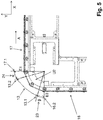
- the transport system 1 denotes a transport system for transporting objects along a transport route TS.
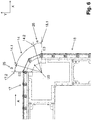
- the transport system 1 comprises at least one hinge-like or chain-like transport element 2 (chain strand) with a multiplicity of transport pallets 3, which are connected to one another in a chain-link-like and articulated manner via chain links 20, namely to the transport element 2, which forms a closed loop and which is connected via a chain wheel 4, for example and at least two more, in the horizontal direction, ie in the direction of the X-axis, or in the vertical direction, ie in the direction of the Y-axis, by means of deflections U1, U2, U3, in the present exemplary embodiment via three further deflections U1, U2, U3 is deflected several times, as shown in the Figures 1 and 2 is shown in more detail.
- the multiple deflected loop SL of the transport element 2 between the chain wheel 4 and the three further deflections U1, U2, U3 is formed in such a way that in the Figure 2
- the top view shown is essentially a rectangle with a free central area MB.
- the transport system 1 thus forms, in particular, a multiple loop SL of the transport element 2 that is deflected in a square shape and has a free central area MB.
- the at least two further deflections U1, U2, U3 can thereby be designed as deflection devices in the form of a deflection curve or deflection roller.
- one of the at least two further deflections U1, U2, U3 is designed as a further chain wheel 4, in particular as a clocked, motor-driven chain wheel.
- the transport system has at least one driven chain wheel 4.
- At least one chain wheel 4 is advantageously provided, which is designed to be driven directly, i.e. gearless, by an electric motor 6, preferably by a torque motor, in at least one transport direction A.
- the chain wheel 4 is mounted in a machine frame 7 with its axis 4.1 in the vertical direction or essentially in the vertical direction, i.e. oriented parallel to the Z axis.
- the multiple deflected loop SL formed by the transport element 2 is thus arranged in a horizontal or essentially horizontal plane, i.e. in the XY plane.
- the transport pallets 3 are each provided with a receptacle 3.11 for receiving objects (e.g. workpieces or other products) that are moved in transport direction A with the rotating transport element 2.
- the transport pallets 3 are each on both sides by means of the Machine frame 7 provided transport pallet guides 30, 31, in particular a first and second transport pallet guide 30, 31, out.
- the transport pallets 3 are guided on both sides between the chain wheel 4 and the first deflections U1 following in the transport direction A by means of the transport pallet guides 30, 31 provided on the machine frame 7.
- the transport pallets 3 are then deflected around the first deflection U1 before the transport pallets 3 are then guided again following in the transport direction A between the first and second deflection U1, U2 on both sides by means of the transport pallet guides 30, 31 provided on the machine frame 7. Analogous to this, the transport pallets 3 are again deflected around the second deflection U2 before the transport pallets 3 are then guided again in the transport direction A between the second and third deflection U2, U3 on both sides by means of the transport pallet guides 30, 31 provided on the machine frame 7 .
- transport pallets 3 are then again deflected around the third deflection U3, before the transport pallets 3 then again following in the transport direction A between the third deflection U3 and the chain wheel 4 are guided on both sides by means of the transport pallet guides 30, 31 provided on the machine frame 7.
- the linear and rectilinear transport pallet guides 30, 31 arranged on the machine frame 7 each extend at least between the chain wheel 4 and the correspondingly adjacent first and third deflection U1, U3, or between the first and second deflection U1, U2 and guides the transport element 2, in particular the individual transport pallets 3 of the transport element 2, at least in this transport section along the transport route TS - that is, in the transport section of the transport route TS in which the transport pallets 3 are out of engagement with the sprocket 4.
- the individual transport pallets 3 are thus guided at least in sections along the transport path TS on both sides by means of the first and second guide devices 30 and 31.
- the transport pallet guides 30, 31 following one another in transport direction A between the chain wheel 4 and / or one of the deflections U1, U2, U3 do not run parallel, but at an angle ⁇ smaller than 180 °, preferably at an angle ⁇ smaller or equal to 120 °, particularly advantageously at an angle ⁇ less than or equal to 90 °.
- the transport pallet guides 30, 31 provided between the chain wheel 4 and the first deflection U1 preferably form an angle ⁇ of approximately 90 ° with the transport pallet guides 30, 31 which follow adjacent in the transport direction A between the first deflection U1 and the second deflection U2.
- the transport pallet guides 30, 31 provided between the first deflection U1 and the second deflection U2 form an angle ⁇ of approximately 90 ° to the transport pallet guides 30, 31 which follow adjacent in the transport direction A between the second deflection U2 and the third deflection U3.
- the transport pallet guides 30, 31 provided between the second deflection U2 and the third deflection U3 form an angle ⁇ of approximately 90 ° to the transport pallet guides 30, 31 which follow adjacent in the transport direction A between the third deflection U3 and the sprocket 4.
- the multiple deflected loop SL of the transport element 2 thus essentially forms a rectangle with a free central area MB between the chain wheel 4 and / or the three further deflections U1, U2, U3 in plan view.
- the transport system 1 thus forms, in particular, a multiple loop SL of the transport element 2 that is deflected in a square shape and has a free central area MB. In the free central area MB, installation space is thus created in which machine tools interacting with the transport system can be arranged.
- the loop formed by the transport element 2 is in the variant of FIG Figures 1 and 2 arranged in a horizontal or substantially horizontal plane, ie in the XY plane. Alternatively, however, it is also possible to arrange the loop formed by the transport element 2 in a vertical or essentially vertical plane, that is to say in an XZ plane.
- the spatial alignment of the loop formed by the transport element 2 is not restricted to any of the exemplary embodiments shown. Rather, the transport element 2 can be arranged in any desired orientation in three-dimensional space.
- the transport pallets 3 form a web-like transport or holding surface on their respective upper sides 3.1, on which, for example, a receptacle 3.11, shown in FIG Figure 1 , is provided and specifically for the reception of objects (eg workpieces or other products) that are moved in the transport direction A with the rotating transport element 2.
- objects eg workpieces or other products
- the sprocket 4 is driven by the drive 6 for the Fig. 1 and 2
- the selected representation is driven clockwise according to the arrow B.
- the sprocket 4 is designed as an eight-part sprocket, which has eight sprocket engagement or driving areas or receptacles 8, which act as driving areas for the chain links of the transport element 2 and preferably at regular angular intervals, i.e. pitch angle TW on a circular path or pitch circle 8.1 around the Rotate axis 4.1 of the chain wheel 4.
- the pocket-like recesses 8 open to the circumference of the chain wheel 4 each form a "chain wheel tooth" between them and have a pitch angle TW which is equal to the chain link length KL of the chain links of the transport element 2, ie the length of each transport pallet 3 or the center distance between two in Transport direction A consecutive joint axes GAS.
- the engagement or driving areas 8 of the sprocket 4 engage, depending on the rotational position, in a first and second guide and bearing device 32, 33 formed on the respective joint axes GAS, which are preferably attached to the respective free ends GAS1, GAS2 of a joint axis GAS of the chain joint 20 of the respective Transport pallets 3 are provided.
- the first and second guide and bearing devices 32, 33 which are provided at the free ends of the respective joint axes GAS of the chain joint 4, engage positively in the engagement or driving areas 8 of the sprocket 4 depending on the rotational position, so that by means of the at least one driven chain wheel 4, a drive movement in the transport direction A can be transmitted to the transport element 2.
- the respective joint axis GAS of the corresponding chain joint 20 can be designed as a one-piece, in particular one-piece joint rod, which extends between its first and second free ends GAS1, GAS2 in such a way that the chain joint 20 has a joint axis running between the first and second guide devices 30, 31 GAS.
- the joint axis GAS forms a joint pin of the chain joint 20 between two adjacent transport pallets 3.
- the transport pallets 3 When the drive 6 is switched on, the transport pallets 3 thus move in the transport direction A on a path of movement, generally designated 10 in the figures, corresponding to the closed, multiply deflected loop SL of the transport element 2, which initially has four circular arc-shaped sections 11, 12, 13 and 14, of which the section 11 between the transport pallet inlet 11.1 and the transport pallet outlet 11.2 of the chain wheel 4, the section 12 between the transport pallet inlet 12.1 and the transport pallet outlet 12.2 of the first deflection U1, the section 13 between the transport pallet inlet 13.1 and the transport pallet outlet 13.2 of the second deflection U2, and the section 14 is formed between the transport pallet inlet 14.1 and the transport pallet outlet 14.2 of the third deflection U3.
- the movement path 10 further comprises four straight sections 15, 16, 17 and 18, which extend in the X direction or Y direction between the chain wheel 4 and / or the deflections U1, U2, U3.
- a transport pallet inlet 15.1 of section 15 and the transport pallet outlet 17.2 of section 17 are located in a horizontal YZ plane that includes axis 4.1 and is designated E2. There is a parallel to level E2 Transport pallet outlet 15.2 of section 15 and the transport pallet inlet 17.1 of section 17 in a plane E1.
- a transport pallet inlet 16.1 of section 16 and the transport pallet outlet 18.2 of section 18 are located in a horizontal YZ plane which includes axis 4.1 and is designated E4.
- a transport pallet outlet 16.2 of section 16 and the transport pallet inlet 18.1 of section 18 are located parallel to plane E4 in a plane E3.
- the plane E2 intersects the plane E4 perpendicularly in the axis 4.1.
- the individual transport pallets 3 are therefore guided on both sides by means of the first and second transport pallet guides 30 and 31 at least in the respective straight sections 15 to 18 along the transport path TS.
- the radial sections 11 to 14 are all of the same length and are oriented to the pitch angle TW of the sprocket 4 or are dimensioned according to this.
- the length of the radial sections 11 to 14 corresponds to the pitch angle TW of the chain wheel 4.
- the transport pallet inlets 11.1, 12.1, 13.1, 14.1, 15.1, 16.1, 17.1, 18.1 and the transport pallet outlets 11.2, 12.2, 13.2, 14.2, 15.2, 16.2 , 17.2, 18.2 are determined by the pitch angle TW of the chain wheel 4.
- Transport pallet inlets 11.1, 12.1, 13.1, 14.1, 15.1, 16.1, 17.1, 18.1 and the transport pallet outlets 11.2, 12.2, 13.2, 14.2, 15.2, 16.2, 17.2, 18.2 can thus be understood to mean that angular position of the rotary movement of the chain wheel 4 at which the respective transport pallet 3 grasped by the chain wheel 4 in a fully form-fitting manner or is released again from the form connection with the chain wheel 4.
- the transport pallet inlets 11.1, 12.1, 13.1, 14.1, 15.1, 16.1, 17.1, 18.1 are each in the direction of rotation B by 22.5 ° with respect to the plane enclosing the axis of the chain wheel 4 and the plane that intersects the straight sections 15, 17 orthogonally E1 and E2 offset in such a way that the transport pallet inlets 11.1, 12.1, 13.1, 14.1, 15.1, 16.1, 17.1, 18.1 each follow in the direction of rotation B on this plane E1 and E2.
- the transport pallet outlets 11.2, 12.2, 13.2, 14.2, 15.2, 16.2, 17.2, 18.2 are offset by 22.5 ° with respect to the plane E3 and E4 which includes the axis 4.1 and which intersects the straight sections 16, 18 orthogonally that the relevant transport pallet outlet is in direction of rotation B in front of level E3 or E4.
- the respective transport pallet inlet 11.1, 12.1, 13.1, 14.1, 15.1, 16.1, 17.1, 18.1 is around an angular range ⁇ , ⁇ of 22.5 degrees offset in the respective direction of rotation B of the sprocket 4, that is, by an angular range ⁇ , ⁇ which corresponds to half the pitch angle TW.
- the movement path 10 also includes sections 19-26, of which the section 19 is between the transport pallet outlet 18.2 and the transport pallet inlet 11.1, the section 20 between the transport pallet outlet 11.2 and the transport pallet inlet 15.1, the section 21 between the transport pallet outlet 15.2 and the transport pallet inlet 12.1 and the Section 22 between the transport pallet outlet 12.2 and the transport pallet inlet 16.1, the section 23 between the transport pallet outlet 16.2 and the transport pallet inlet 13.1, the section 24 between the transport pallet outlet 13.2 and the transport pallet inlet 17.1, the section 25 between the transport pallet outlet 17.2 and the transport pallet inlet 14.1 and the section 26 extend between the transport pallet outlet 14.2 and the transport pallet inlet 18.1.
- the sections 19-26 therefore each extend over the angular range ⁇ , ⁇ of 22.5 ° degrees.
- the sections 19-26 are designed, at least with regard to the horizontal or vertical guidance or the radial guidance (based on the axis 4.1) of the transport pallets 3 in the manner described in more detail below, so that when the chain-like transport element 2 rotates, the polygon effect is completely compensated for (Polygon adjustment) is achieved.
- a compensation curve 28, 28a is assigned to each of the sections 19-26, or a compensation curve 28, 28a is formed in each of the sections 19-26 in the manner described in more detail below.
- the respective compensation curve 28, 28a extends over the respective section 19-26, so that the corresponding compensation curve 28, 28a each extends over an angular range ⁇ , ⁇ which corresponds to half the pitch angle TW of the sprocket meshing or driving regions 8, i.e. over an angle ⁇ , ⁇ of 22.5 °.
- the sections 20, 22, 24 and 26 are basically identical in terms of the course of the transport pallet guide 30, 31 for the transport pallets 3 and each only extend as far as the level E3 or E4.
- the sections 19, 21, 23 and 25 are basically identical in terms of the course of the transport pallet guide 30, 31 for the transport pallets 3 and each only extend as far as the level E1 or E3.
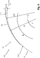
- the Figure 9 exemplarily on the basis of section 24 the course of the compensation curves 28 valid for the sections 20, 22, 24 and 26 and the Figure 10 as an example of section 25, the course of compensation curves 28a valid for sections 19, 21, 23 and 25.
- the respective joint axis GAS of a corresponding chain joint 20 at a first free end GAS1 with the first guide and storage device 32 in the first transport pallet guide 30 and at a second free end GAS2 with the second guide and storage device 33 in the second transport pallet guide 31 out, in particular in two opposite and parallel to the transport direction A and thus preferably perpendicular to the joint axis GAS oriented guide planes FE1, FE2.
- the first and second transport pallet guides 30, 31 in the variant of FIG Figure 8 thus a horizontal guide at least in the straight section 15 to 18 along the transport path TS for the respective joint axis GAS.
- first and second guide and bearing devices 32, 33 each include at least one first and second roller bearing 34 ... 37, which can be designed, for example, as a roller rotatably mounted about the joint axis GAS of the corresponding chain joint 20, and between a first and second guide surfaces 30.1, 30.2 and 31.1, 31.2 of the respective first and second transport pallet guides 30, 31, which lie opposite one another and run parallel to the joint axis GAS.
- first and second roller bearings 34, 35 of the first guide and bearing device 32 are between the opposing guide surfaces 30.1, 30.2 of the first transport pallet guide 30, which run parallel to the joint axis GAS, and the first and second roller bearings 36, 37 of the second guide and bearing device Bearing device 33 guided between the opposite guide surfaces 31.1, 31.2 of the second transport pallet guide 31, which run parallel to the joint axis GAS.
- first and second roller bearings 34 ... 37 of the respective first and second guide and bearing devices 32, 33 between the respective guide surfaces 30.1, 30.2 and 31.1, 31.2 of the corresponding first and second transport pallet guides 30, 31 are parallel to the transport direction A. guided and thus in particular perpendicular to the management levels FE1 and FE2.
- first roller bearing 34 of the first guide and bearing device 32 is provided in the area of the first free end GAS1 so that it can rotate about the joint axis GAS, while the second roller bearing 35 is on the side of the first one facing the second free end GAS2 Roller bearing 34 is also provided rotatably about the hinge axis GAS on this, namely the first roller bearing 34, preferably immediately adjacent to it, for example with a contact fit subsequently.
- the first roller bearing 34 of the first guide and bearing device 32 forms a first outer roller bearing 34 and the second roller bearing 35 forms a second inner roller bearing 35, which extends along the joint axis GAS by approximately the width of the first outer roller bearing 34 is provided offset in the direction of the second free end GAS2 on the joint axis GAS immediately adjacent to the first outer roller bearing 34.
- the first roller bearing 36 of the second guide and bearing device 33 is provided rotatable around the hinge axis GAS in the area of the second free end GAS2, while the second roller bearing 37 is also provided on the side of the first roller bearing 36 facing the first free end GAS1 provided rotatably about the hinge axis GAS, preferably immediately adjacent to the first roller bearing 36, for example connected in a contact-locking manner.
- the first roller bearing 36 of the second guide and bearing device 33 thus forms a first outer roller bearing 36 and the second roller bearing 37 forms a second inner roller bearing 37, which extends along the joint axis GAS by approximately the width of the first outer roller bearing 36 offset in the direction of the first free end GAS1 is provided on the joint axis GAS immediately adjacent to the first outer roller bearing 36.
- the respective first roller bearing 34, 36 of the first and second guide and bearing device 32, 33 are in a first contact section 30.11, 31.11 of the respective first guide surface 30.1, 31.1 and the second roller bearing 35, 37 in a respective second contact section 30.21, 31.21 of the respective second guide surface 30.2, 31.2 abutting and pretensioned to one another, the respective first and second contact sections 30.11 and 30.21 or 31.11 and 31.21 being offset from one another along the hinge axis GAS and provided opposite one another.
- the first roller bearing 34 of the first guide and bearing device 32 is guided in the first transport pallet guide 30 and the first roller bearing 36 in a pretensioned manner on the first contact section 30.11 of the first guide surface 30.1, resting against the second contact section 30.21 of the second guide surface 30.2 of the second guide and bearing device 33 on the first contact section 31.11 of the first guide surface 31.1 in a pretensioned manner against the second roller bearing 37 in the second transport pallet guide 31 in the second transport pallet guide 31 in contact with the second contact section 31.21 of the second guide surface 31.2.
- first roller bearing 34 of the first guide and bearing device 32 is advantageously in contact with the first contact section 30.11 of the first guide surface 30.1 and the second roller bearing 35 in contact with the second contact section 30.21 of the second guide surface 30.2 is guided in the first transport pallet guide 30 in a pretensioned manner compared to the one on the First contact section 31.11 of the first guide surface 31.1, the first roller bearing 36 of the second guide and bearing device 33 and the second roller bearing 37 of the second transport pallet guide 31, which is guided against the second contact section 31.21 of the second guide surface 31.2.
- prestressing forces directed perpendicularly to the hinge axis GAS act in the area of the first guide and storage device 32, respectively, from the first and second contact section 30.11, 30.21 of the first transport pallet guide 30 thus offset along the hinge axis GAS and opposite one another, i.e.
- the first transport pallet guide 30 forms a first guide space FR1 between the first and second guide surfaces 30.1, 30.2, which springs back into the first guide space FR1 in the area of the first and second contact surfaces 30.11, 30.21, i.e.
- first guide roller 34 of the first guide and bearing device 32 rests on the first guide surface 30.1 in the area of the first contact section 30.11 that jumps back into the first guide space FR1 and the second guide roller 35 rests on the second guide surface 30.2 in the area of the second contact section that jumps back into the first guide space FR1 30.21 is applied, while the second guide roller 35 of the first guide and bearing device 32 comes free of the first guide surface 30.1 on the section that does not spring back into the first guide space FR1, i.e. in particular does not contact and the first guide roller 34 comes free of the subsection of the second guide surface 30.2 that does not spring back into the first guide space FR1.
- the second transport pallet guide 31 also forms a second guide space FR2 between the first and second guide surfaces 31.1, 31.2, which springs back into the second guide space FR2 in the area of the first and second contact surfaces 31.11, 31.21, that is to say is stepped in this area, in such a way that that the first guide roller 36 of the second guide and bearing device 33 rests on the first guide surface 31.1 in the area of the first contact section 31.11 that springs back into the second guide space FR2 and the second guide roller 37 on the second guide surface 31.2 in the area of the second that springs back into the second guide space FR2 Contact section 31.21 is applied, while the second guide roller 37 of the second guide and bearing device 33 comes free of the first guide surface 31.1 on the section that does not spring back into the second guide space FR2, i.e. in particular does not contact and the first guide roller 36 does not move from the second en guide space FR2 recessed subsection of the second guide surface 31.2 comes free.
- the hinge axis GAS can be fixed firmly but detachably in a hinge section 20.1 of the respective transport pallet 3 via a holding means 40, for example a grub screw, and prevented from rotating, i.e. a rotation around the longitudinal extent of the hinge axis GAS.
- first roller bearings 34, 36 are only located on the first contact section, 30.11 , 31.11 of the respective first guide surface 30.1, 31.1 and the second roller bearings 35, 37 roll or roll only in contact with the second system section 30.21, 31.21 of the respective second guide surface 30.2, 31.2.
- the Figure 8 an embodiment of the transport pallets 3, in which two further rotatable roller bearings 50, 51 are arranged on the corresponding transport pallet 3 between two adjacent hinge axes GAS on the underside 3.2 opposite the top 3.1, which in the embodiment shown for the vertical guidance of the transport pallets 3 between the first and second transport pallet guides 30, 31 and a further guide rail 52 provided between the two roller bearings 50, 51 are guided.
- the guide rail 52 can be attached to the first and second transport pallet guides 30, 31, in particular to the underside of which, for example, forms a guide device base, arranged, in particular screwed.
- the two roller layers 40, 51 for this purpose lie in particular on the central guide rail 52 extending parallel to the transport direction A and roll or roll on this.
- Figure 7 shows a perspective view of an exemplary embodiment of two exposed and articulated transport pallets 3 of the transport system 1 according to the invention connected to one another via a chain hinge 20.
- the transport pallets 3 have an elastic connecting section 53 in their respective joint section 20.1 on their respective upper sides 3.1, which connects the respective joint section 20.1 of two adjacent transport pallets 3 spanned elastically.
- the connecting section 53 can be arranged, in particular riveted, on the respective upper sides 3.1 of two adjacent transport pallets 3 in an elastically prestressed manner.
- the connecting section 53 can be made from an elastic natural and / or artificial textile fabric.
- the first and second transport pallet guides 30, 31 are designed so that at least the first roller bearings 34, 36 of a corresponding joint axis GAS of a chain joint 20 move on a compensation curve 28 or are guided on the compensation curve 28, which corresponds to the Fig. 9 with increasing angular range ⁇ (in the direction of rotation B about the axis 4.1 of the chain wheel 4) from the transport pallet outlet 13.2 radially an increasing distance ⁇ .
- the distance ⁇ increases over the angular range ⁇ after half the pitch angle TW of one of the chain wheels 4 or 2, as seen in the direction of rotation B. half a chain length KL of a transport pallet 3 was passed through.
- the respective compensation curve 28 is therefore formed in the second half of the pitch angle TW, while the compensation curve 28a is formed in the first half of the pitch angle TW, as shown in FIG Figure 10 is shown in more detail.
- R denotes the radius of the pitch circle 8.1, ie the center distance that exists between the axis 4.1 and the joint axis GAS between two transport pallets 3 when this joint axis GAS is located on the sections 11 to 14 of the orbit 10.
- the radial distance between the compensation curve 28 and the axis 4.1 is designated by r24.
- the course of the compensation curves 28a at the sections 19, 21, 23 and 25 is mirror-symmetrical to the compensation curves 28 at the sections 20, 22, 24, 26.
- the compensation curves 28, 28a have the same relative course with respect to the generated distance ⁇ on the respective angular range ⁇ , ⁇ .
- the compensation curve 28 at the sections 20, 22, 24 and 26 is designed mirror-symmetrically to the compensation curve 24a of the sections 19, 21, 23 and 25, specifically in relation to a respective central plane, not shown.
- the course of the compensation curves 28a of the sections 19, 21, 23 and 25 is shown in FIG Figures 10 shown.
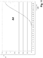
- the fundamental course of the distance ⁇ as a function of the angular range ⁇ or ⁇ , which is independent of the specific dimensions of the transport system 1, is derived from FIG Fig. 11 evident.
- the distance ⁇ initially has a flat inlet, then a steeper but straight rise compared to the inlet, which is then in the area of the outlet, i.e. before reaching the entire angular range ⁇ or ⁇ , flattens again and merges into the transport pallet guide 30, 31 of the section 15 to 18.
- the maximum value of the distance ⁇ is equal to the offset d.
- ⁇ depending on the angular distance ⁇ or ⁇ , has a sine-like, preferably essentially sinus-shaped profile, with a flat inlet in an angular range ⁇ or ⁇ from 0 ° degrees to approximately 8 ° degrees, followed by a Compared to the inlet, it has a steeper but straight rise in an angle range ⁇ or ⁇ between 8 ° degrees to about 19 ° degrees, which is then in the area of the outlet, i.e. before reaching the entire angle range ⁇ or ⁇ , in an angle range ⁇ or ⁇ between 19 ° degrees to 22.5 ° degrees and the transport pallet guide 30, 31 of the section 13 and 14 passes over.
- the essentially sinusoidal course of the difference ⁇ between the compensation curve 28 or 28a and the pitch circle 8.1 on which the sprocket engagement or driving areas 8 move, is independent of the special dimensions of the transport system but typical for the compensation curves 28 and 28a of the transport system according to the invention or for the course of the guides of the sections 19-26, which are each provided between the straight sections 15 to 18 and the chain wheel 4 and / or the deflectors U1, U2, U3 or the transport pallet inlets and outlets there .
- the compensation curves 28 and 28a are always designed so that the compensation curve in no way intersects the pitch circle 8.1, i.e. the distance ⁇ between the compensation curve 28, 28a and the pitch circle 8.1 is zero or greater than zero.
- the compensating curves 28, 28a can be arranged on the corresponding transport pallet guide 30, 31, in particular permanently connected to it.
- the compensating curves 28, 28a can be formed in one piece with the corresponding transport pallet guide 30, 31. It can also be provided that the compensation curves 28, 28a are formed in one piece with the deflections U1, U2, U3.
Landscapes
- Engineering & Computer Science (AREA)
- Mechanical Engineering (AREA)
- Chain Conveyers (AREA)
- Threshing Machine Elements (AREA)
Applications Claiming Priority (1)
| Application Number | Priority Date | Filing Date | Title |
|---|---|---|---|
| DE102019118663.3A DE102019118663A1 (de) | 2019-07-10 | 2019-07-10 | Transportsystem sowie Behandlungsmaschine mit einem solchen Transportsystem |
Publications (2)
| Publication Number | Publication Date |
|---|---|
| EP3763639A1 true EP3763639A1 (fr) | 2021-01-13 |
| EP3763639B1 EP3763639B1 (fr) | 2023-02-22 |
Family
ID=70802767
Family Applications (1)
| Application Number | Title | Priority Date | Filing Date |
|---|---|---|---|
| EP20176002.2A Active EP3763639B1 (fr) | 2019-07-10 | 2020-05-22 | Système de transport ainsi que machine de traitement dotée d'un tel système de transport |
Country Status (7)
| Country | Link |
|---|---|
| EP (1) | EP3763639B1 (fr) |
| DE (1) | DE102019118663A1 (fr) |
| DK (1) | DK3763639T3 (fr) |
| ES (1) | ES2940789T3 (fr) |
| FI (1) | FI3763639T3 (fr) |
| HU (1) | HUE061447T2 (fr) |
| PL (1) | PL3763639T3 (fr) |
Cited By (1)
| Publication number | Priority date | Publication date | Assignee | Title |
|---|---|---|---|---|
| CN113911700A (zh) * | 2021-08-31 | 2022-01-11 | 广东文灿压铸科技有限公司 | 一种轿车变速箱壳体的搬运系统 |
Families Citing this family (1)
| Publication number | Priority date | Publication date | Assignee | Title |
|---|---|---|---|---|
| DE102021107189A1 (de) | 2021-03-23 | 2022-09-29 | Taktomat Kurvengesteuerte Antriebssysteme Gmbh | Transportsystem |
Citations (8)
| Publication number | Priority date | Publication date | Assignee | Title |
|---|---|---|---|---|
| FR2546142A1 (fr) * | 1983-05-17 | 1984-11-23 | Metanic Sa | Dispositif d'entrainement de bande transporteuse, notamment pour four de traitement thermique |
| DE3542198A1 (de) * | 1985-11-29 | 1987-06-04 | Elastogran Masch Bau | Doppelplattenband zur kontinuierlichen herstellung von kaschierten schaumstoffbloecken |
| DE3990012C1 (de) * | 1988-01-07 | 2000-11-09 | Walter Sticht | Anlage zur Bearbeitung und/oder Montage von Bauteilen |
| DE102012104213A1 (de) | 2012-05-15 | 2013-11-21 | Taktomat Kurvengesteuerte Antriebssysteme Gmbh | Transportstrecke für Behandlungsmaschinen sowie Behandlungsmaschine |
| DE102013206961A1 (de) * | 2013-04-17 | 2014-10-23 | Bielomatik Leuze Gmbh + Co. Kg | Vorrichtung zum linearen Transport von flächigen Gegenständen |
| DE102015107113A1 (de) | 2015-01-20 | 2016-07-21 | Taktomat Kurvengesteuerte Antriebssysteme Gmbh | Transportsystem sowie Behandlungsmaschine mit einem solchen Transportsystem |
| WO2016140564A1 (fr) * | 2015-02-05 | 2016-09-09 | Rexnord Flattop Europe B.V. | Transporteur à chaîne à distance réglable entre les arbres |
| DE102016108765A1 (de) * | 2016-05-12 | 2017-11-16 | Taktomat Kurvengesteuerte Antriebssysteme Gmbh | Transportsystem |
Family Cites Families (3)
| Publication number | Priority date | Publication date | Assignee | Title |
|---|---|---|---|---|
| DE102011018942B4 (de) * | 2011-03-15 | 2018-10-18 | Taktomat Kurvengesteuerte Antriebssysteme Gmbh | Transportstrecke für Behandlungsmaschinen sowie Behandlungsmaschine |
| DE102011018943A1 (de) * | 2011-03-15 | 2012-09-20 | Taktomat Kurvengesteuerte Antriebssysteme Gmbh | Transportstrecke für Behandlungsmaschinen sowie Behandlungsmaschine |
| DE102018100409B4 (de) * | 2018-01-10 | 2021-10-21 | Taktomat Kurvengesteuerte Antriebssysteme Gmbh | Transportsystem sowie Behandlungsmaschine mit einem solchen Transportsystem |
-
2019
- 2019-07-10 DE DE102019118663.3A patent/DE102019118663A1/de not_active Ceased
-
2020
- 2020-05-22 FI FIEP20176002.2T patent/FI3763639T3/en active
- 2020-05-22 PL PL20176002.2T patent/PL3763639T3/pl unknown
- 2020-05-22 HU HUE20176002A patent/HUE061447T2/hu unknown
- 2020-05-22 ES ES20176002T patent/ES2940789T3/es active Active
- 2020-05-22 EP EP20176002.2A patent/EP3763639B1/fr active Active
- 2020-05-22 DK DK20176002.2T patent/DK3763639T3/da active
Patent Citations (8)
| Publication number | Priority date | Publication date | Assignee | Title |
|---|---|---|---|---|
| FR2546142A1 (fr) * | 1983-05-17 | 1984-11-23 | Metanic Sa | Dispositif d'entrainement de bande transporteuse, notamment pour four de traitement thermique |
| DE3542198A1 (de) * | 1985-11-29 | 1987-06-04 | Elastogran Masch Bau | Doppelplattenband zur kontinuierlichen herstellung von kaschierten schaumstoffbloecken |
| DE3990012C1 (de) * | 1988-01-07 | 2000-11-09 | Walter Sticht | Anlage zur Bearbeitung und/oder Montage von Bauteilen |
| DE102012104213A1 (de) | 2012-05-15 | 2013-11-21 | Taktomat Kurvengesteuerte Antriebssysteme Gmbh | Transportstrecke für Behandlungsmaschinen sowie Behandlungsmaschine |
| DE102013206961A1 (de) * | 2013-04-17 | 2014-10-23 | Bielomatik Leuze Gmbh + Co. Kg | Vorrichtung zum linearen Transport von flächigen Gegenständen |
| DE102015107113A1 (de) | 2015-01-20 | 2016-07-21 | Taktomat Kurvengesteuerte Antriebssysteme Gmbh | Transportsystem sowie Behandlungsmaschine mit einem solchen Transportsystem |
| WO2016140564A1 (fr) * | 2015-02-05 | 2016-09-09 | Rexnord Flattop Europe B.V. | Transporteur à chaîne à distance réglable entre les arbres |
| DE102016108765A1 (de) * | 2016-05-12 | 2017-11-16 | Taktomat Kurvengesteuerte Antriebssysteme Gmbh | Transportsystem |
Cited By (1)
| Publication number | Priority date | Publication date | Assignee | Title |
|---|---|---|---|---|
| CN113911700A (zh) * | 2021-08-31 | 2022-01-11 | 广东文灿压铸科技有限公司 | 一种轿车变速箱壳体的搬运系统 |
Also Published As
| Publication number | Publication date |
|---|---|
| FI3763639T3 (en) | 2023-04-03 |
| ES2940789T3 (es) | 2023-05-11 |
| DE102019118663A1 (de) | 2021-01-14 |
| DK3763639T3 (da) | 2023-03-27 |
| PL3763639T3 (pl) | 2023-07-10 |
| HUE061447T2 (hu) | 2023-07-28 |
| EP3763639B1 (fr) | 2023-02-22 |
Similar Documents
| Publication | Publication Date | Title |
|---|---|---|
| EP3954634B1 (fr) | Système de transport, ainsi que machine de traitement dotée d'un tel système de transport | |
| DE102018100409B4 (de) | Transportsystem sowie Behandlungsmaschine mit einem solchen Transportsystem | |
| EP0170773B1 (fr) | Engrenage à crémaillère pour la génération d'un mouvement relatif entre deux pièces de machine guidées l'une contre l'autre | |
| DE3990012C1 (de) | Anlage zur Bearbeitung und/oder Montage von Bauteilen | |
| DE102015107113B4 (de) | Transportsystem sowie Behandlungsmaschine mit einem solchen Transportsystem | |
| DE102012104213B4 (de) | Transportsystem für Behandlungsmaschinen sowie Behandlungsmaschine | |
| EP0340639A1 (fr) | Installation d'assemblage | |
| EP3763639A1 (fr) | Système de transport ainsi que machine de traitement dotée d'un tel système de transport | |
| DE102007032546A1 (de) | Kettenglied für eine umlaufende Transportkette einer Werkzeugmaschine, sowie Doppelendprofiler mit aus solchen Kettengliedern gebildeten Führungsketten | |
| DE4211658A1 (de) | Vorschubeinrichtung für Tafeln | |
| DE102011018942B4 (de) | Transportstrecke für Behandlungsmaschinen sowie Behandlungsmaschine | |
| DE102011018943A1 (de) | Transportstrecke für Behandlungsmaschinen sowie Behandlungsmaschine | |
| DE20319366U1 (de) | Durchlaufschleifmaschine zum Bearbeiten einer ebenen Werkstückoberfläche | |
| CH687369A5 (de) | Anlage zur Bearbeitung und/oder Montage von Bauteilen. | |
| EP0080515A1 (fr) | Système de guidage pour la translation d'un porte-outil | |
| DE3013410A1 (de) | Fuehrungssystem fuer lineare bewegungen | |
| DE102016108765B4 (de) | Transportsystem | |
| EP3721100B1 (fr) | Ensemble de liaison | |
| DE19532391A1 (de) | Antriebseinheit für ein endloses Fördermittel eines Fördersystem | |
| DE202019005870U1 (de) | Transportsystem sowie Behandlungsmaschine mit einem solchen Transportsystem | |
| DE102023113031B3 (de) | Transportsystem sowie Behandlungsmaschine mit einem solchen Transportsystem | |
| DE102023113019B3 (de) | Transportsystem sowie Behandlungsmaschine mit einem solchen Transportsystem | |
| DE102016010092B3 (de) | Drehtisch | |
| EP1980359A1 (fr) | Unité de réglage | |
| DE8912348U1 (de) | Schrittantriebsvorrichtung |
Legal Events
| Date | Code | Title | Description |
|---|---|---|---|
| PUAI | Public reference made under article 153(3) epc to a published international application that has entered the european phase |
Free format text: ORIGINAL CODE: 0009012 |
|
| STAA | Information on the status of an ep patent application or granted ep patent |
Free format text: STATUS: THE APPLICATION HAS BEEN PUBLISHED |
|
| AK | Designated contracting states |
Kind code of ref document: A1 Designated state(s): AL AT BE BG CH CY CZ DE DK EE ES FI FR GB GR HR HU IE IS IT LI LT LU LV MC MK MT NL NO PL PT RO RS SE SI SK SM TR |
|
| AX | Request for extension of the european patent |
Extension state: BA ME |
|
| STAA | Information on the status of an ep patent application or granted ep patent |
Free format text: STATUS: REQUEST FOR EXAMINATION WAS MADE |
|
| 17P | Request for examination filed |
Effective date: 20210617 |
|
| RBV | Designated contracting states (corrected) |
Designated state(s): AL AT BE BG CH CY CZ DE DK EE ES FI FR GB GR HR HU IE IS IT LI LT LU LV MC MK MT NL NO PL PT RO RS SE SI SK SM TR |
|
| GRAP | Despatch of communication of intention to grant a patent |
Free format text: ORIGINAL CODE: EPIDOSNIGR1 |
|
| STAA | Information on the status of an ep patent application or granted ep patent |
Free format text: STATUS: GRANT OF PATENT IS INTENDED |
|
| INTG | Intention to grant announced |
Effective date: 20221130 |
|
| GRAS | Grant fee paid |
Free format text: ORIGINAL CODE: EPIDOSNIGR3 |
|
| GRAA | (expected) grant |
Free format text: ORIGINAL CODE: 0009210 |
|
| STAA | Information on the status of an ep patent application or granted ep patent |
Free format text: STATUS: THE PATENT HAS BEEN GRANTED |
|
| AK | Designated contracting states |
Kind code of ref document: B1 Designated state(s): AL AT BE BG CH CY CZ DE DK EE ES FI FR GB GR HR HU IE IS IT LI LT LU LV MC MK MT NL NO PL PT RO RS SE SI SK SM TR |
|
| REG | Reference to a national code |
Ref country code: GB Ref legal event code: FG4D Free format text: NOT ENGLISH |
|
| REG | Reference to a national code |
Ref country code: CH Ref legal event code: EP |
|
| REG | Reference to a national code |
Ref country code: DE Ref legal event code: R096 Ref document number: 502020002554 Country of ref document: DE |
|
| REG | Reference to a national code |
Ref country code: AT Ref legal event code: REF Ref document number: 1549385 Country of ref document: AT Kind code of ref document: T Effective date: 20230315 Ref country code: IE Ref legal event code: FG4D Free format text: LANGUAGE OF EP DOCUMENT: GERMAN |
|
| REG | Reference to a national code |
Ref country code: DK Ref legal event code: T3 Effective date: 20230323 |
|
| REG | Reference to a national code |
Ref country code: NL Ref legal event code: FP |
|
| REG | Reference to a national code |
Ref country code: SE Ref legal event code: TRGR |
|
| REG | Reference to a national code |
Ref country code: ES Ref legal event code: FG2A Ref document number: 2940789 Country of ref document: ES Kind code of ref document: T3 Effective date: 20230511 |
|
| REG | Reference to a national code |
Ref country code: LT Ref legal event code: MG9D |
|
| P01 | Opt-out of the competence of the unified patent court (upc) registered |
Effective date: 20230530 |
|
| REG | Reference to a national code |
Ref country code: HU Ref legal event code: AG4A Ref document number: E061447 Country of ref document: HU |
|
| PG25 | Lapsed in a contracting state [announced via postgrant information from national office to epo] |
Ref country code: RS Free format text: LAPSE BECAUSE OF FAILURE TO SUBMIT A TRANSLATION OF THE DESCRIPTION OR TO PAY THE FEE WITHIN THE PRESCRIBED TIME-LIMIT Effective date: 20230222 Ref country code: PT Free format text: LAPSE BECAUSE OF FAILURE TO SUBMIT A TRANSLATION OF THE DESCRIPTION OR TO PAY THE FEE WITHIN THE PRESCRIBED TIME-LIMIT Effective date: 20230622 Ref country code: NO Free format text: LAPSE BECAUSE OF FAILURE TO SUBMIT A TRANSLATION OF THE DESCRIPTION OR TO PAY THE FEE WITHIN THE PRESCRIBED TIME-LIMIT Effective date: 20230522 Ref country code: LV Free format text: LAPSE BECAUSE OF FAILURE TO SUBMIT A TRANSLATION OF THE DESCRIPTION OR TO PAY THE FEE WITHIN THE PRESCRIBED TIME-LIMIT Effective date: 20230222 Ref country code: LT Free format text: LAPSE BECAUSE OF FAILURE TO SUBMIT A TRANSLATION OF THE DESCRIPTION OR TO PAY THE FEE WITHIN THE PRESCRIBED TIME-LIMIT Effective date: 20230222 Ref country code: HR Free format text: LAPSE BECAUSE OF FAILURE TO SUBMIT A TRANSLATION OF THE DESCRIPTION OR TO PAY THE FEE WITHIN THE PRESCRIBED TIME-LIMIT Effective date: 20230222 |
|
| PGFP | Annual fee paid to national office [announced via postgrant information from national office to epo] |
Ref country code: NL Payment date: 20230519 Year of fee payment: 4 Ref country code: DK Payment date: 20230524 Year of fee payment: 4 Ref country code: CZ Payment date: 20230515 Year of fee payment: 4 Ref country code: CH Payment date: 20230602 Year of fee payment: 4 |
|
| PG25 | Lapsed in a contracting state [announced via postgrant information from national office to epo] |
Ref country code: IS Free format text: LAPSE BECAUSE OF FAILURE TO SUBMIT A TRANSLATION OF THE DESCRIPTION OR TO PAY THE FEE WITHIN THE PRESCRIBED TIME-LIMIT Effective date: 20230622 Ref country code: GR Free format text: LAPSE BECAUSE OF FAILURE TO SUBMIT A TRANSLATION OF THE DESCRIPTION OR TO PAY THE FEE WITHIN THE PRESCRIBED TIME-LIMIT Effective date: 20230523 |
|
| PGFP | Annual fee paid to national office [announced via postgrant information from national office to epo] |
Ref country code: SE Payment date: 20230519 Year of fee payment: 4 Ref country code: PL Payment date: 20230512 Year of fee payment: 4 Ref country code: HU Payment date: 20230524 Year of fee payment: 4 Ref country code: FI Payment date: 20230523 Year of fee payment: 4 |
|
| PGFP | Annual fee paid to national office [announced via postgrant information from national office to epo] |
Ref country code: BE Payment date: 20230519 Year of fee payment: 4 |
|
| PG25 | Lapsed in a contracting state [announced via postgrant information from national office to epo] |
Ref country code: SM Free format text: LAPSE BECAUSE OF FAILURE TO SUBMIT A TRANSLATION OF THE DESCRIPTION OR TO PAY THE FEE WITHIN THE PRESCRIBED TIME-LIMIT Effective date: 20230222 Ref country code: RO Free format text: LAPSE BECAUSE OF FAILURE TO SUBMIT A TRANSLATION OF THE DESCRIPTION OR TO PAY THE FEE WITHIN THE PRESCRIBED TIME-LIMIT Effective date: 20230222 Ref country code: EE Free format text: LAPSE BECAUSE OF FAILURE TO SUBMIT A TRANSLATION OF THE DESCRIPTION OR TO PAY THE FEE WITHIN THE PRESCRIBED TIME-LIMIT Effective date: 20230222 |
|
| REG | Reference to a national code |
Ref country code: DE Ref legal event code: R097 Ref document number: 502020002554 Country of ref document: DE |
|
| PG25 | Lapsed in a contracting state [announced via postgrant information from national office to epo] |
Ref country code: SK Free format text: LAPSE BECAUSE OF FAILURE TO SUBMIT A TRANSLATION OF THE DESCRIPTION OR TO PAY THE FEE WITHIN THE PRESCRIBED TIME-LIMIT Effective date: 20230222 |
|
| PLBE | No opposition filed within time limit |
Free format text: ORIGINAL CODE: 0009261 |
|
| STAA | Information on the status of an ep patent application or granted ep patent |
Free format text: STATUS: NO OPPOSITION FILED WITHIN TIME LIMIT |
|
| PG25 | Lapsed in a contracting state [announced via postgrant information from national office to epo] |
Ref country code: MC Free format text: LAPSE BECAUSE OF FAILURE TO SUBMIT A TRANSLATION OF THE DESCRIPTION OR TO PAY THE FEE WITHIN THE PRESCRIBED TIME-LIMIT Effective date: 20230222 |
|
| 26N | No opposition filed |
Effective date: 20231123 |
|
| PG25 | Lapsed in a contracting state [announced via postgrant information from national office to epo] |
Ref country code: SI Free format text: LAPSE BECAUSE OF FAILURE TO SUBMIT A TRANSLATION OF THE DESCRIPTION OR TO PAY THE FEE WITHIN THE PRESCRIBED TIME-LIMIT Effective date: 20230222 Ref country code: MC Free format text: LAPSE BECAUSE OF FAILURE TO SUBMIT A TRANSLATION OF THE DESCRIPTION OR TO PAY THE FEE WITHIN THE PRESCRIBED TIME-LIMIT Effective date: 20230222 Ref country code: LU Free format text: LAPSE BECAUSE OF NON-PAYMENT OF DUE FEES Effective date: 20230522 |
|
| REG | Reference to a national code |
Ref country code: IE Ref legal event code: MM4A |
|
| PG25 | Lapsed in a contracting state [announced via postgrant information from national office to epo] |
Ref country code: IE Free format text: LAPSE BECAUSE OF NON-PAYMENT OF DUE FEES Effective date: 20230522 |
|
| PG25 | Lapsed in a contracting state [announced via postgrant information from national office to epo] |
Ref country code: IE Free format text: LAPSE BECAUSE OF NON-PAYMENT OF DUE FEES Effective date: 20230522 |
|
| PGFP | Annual fee paid to national office [announced via postgrant information from national office to epo] |
Ref country code: DE Payment date: 20240529 Year of fee payment: 5 |
|
| PGFP | Annual fee paid to national office [announced via postgrant information from national office to epo] |
Ref country code: ES Payment date: 20240627 Year of fee payment: 5 |
|
| PGFP | Annual fee paid to national office [announced via postgrant information from national office to epo] |
Ref country code: FR Payment date: 20240527 Year of fee payment: 5 |
|
| PGFP | Annual fee paid to national office [announced via postgrant information from national office to epo] |
Ref country code: IT Payment date: 20240524 Year of fee payment: 5 |