EP3763639A1 - Transport system and treatment machine with such a transport system - Google Patents
Transport system and treatment machine with such a transport system Download PDFInfo
- Publication number
- EP3763639A1 EP3763639A1 EP20176002.2A EP20176002A EP3763639A1 EP 3763639 A1 EP3763639 A1 EP 3763639A1 EP 20176002 A EP20176002 A EP 20176002A EP 3763639 A1 EP3763639 A1 EP 3763639A1
- Authority
- EP
- European Patent Office
- Prior art keywords
- transport
- guide
- chain wheel
- transport pallet
- chain
- Prior art date
- Legal status (The legal status is an assumption and is not a legal conclusion. Google has not performed a legal analysis and makes no representation as to the accuracy of the status listed.)
- Granted
Links
- 238000011282 treatment Methods 0.000 title claims description 13
- 102100036683 Growth arrest-specific protein 1 Human genes 0.000 claims description 10
- 101001072723 Homo sapiens Growth arrest-specific protein 1 Proteins 0.000 claims description 10
- 238000004519 manufacturing process Methods 0.000 claims description 5
- 102100036685 Growth arrest-specific protein 2 Human genes 0.000 description 7
- 101001072710 Homo sapiens Growth arrest-specific protein 2 Proteins 0.000 description 7
- 230000000694 effects Effects 0.000 description 6
- 238000011161 development Methods 0.000 description 3
- 230000018109 developmental process Effects 0.000 description 3
- 230000000284 resting effect Effects 0.000 description 3
- 238000009434 installation Methods 0.000 description 2
- 230000000712 assembly Effects 0.000 description 1
- 238000000429 assembly Methods 0.000 description 1
- 239000004744 fabric Substances 0.000 description 1
- 238000007689 inspection Methods 0.000 description 1
- 238000003754 machining Methods 0.000 description 1
- 238000012986 modification Methods 0.000 description 1
- 230000004048 modification Effects 0.000 description 1
- 239000004753 textile Substances 0.000 description 1
Images


Classifications
-
- B—PERFORMING OPERATIONS; TRANSPORTING
- B65—CONVEYING; PACKING; STORING; HANDLING THIN OR FILAMENTARY MATERIAL
- B65G—TRANSPORT OR STORAGE DEVICES, e.g. CONVEYORS FOR LOADING OR TIPPING, SHOP CONVEYOR SYSTEMS OR PNEUMATIC TUBE CONVEYORS
- B65G21/00—Supporting or protective framework or housings for endless load-carriers or traction elements of belt or chain conveyors
- B65G21/20—Means incorporated in, or attached to, framework or housings for guiding load-carriers, traction elements or loads supported on moving surfaces
- B65G21/22—Rails or the like engaging sliding elements or rollers attached to load-carriers or traction elements
-
- B—PERFORMING OPERATIONS; TRANSPORTING
- B65—CONVEYING; PACKING; STORING; HANDLING THIN OR FILAMENTARY MATERIAL
- B65G—TRANSPORT OR STORAGE DEVICES, e.g. CONVEYORS FOR LOADING OR TIPPING, SHOP CONVEYOR SYSTEMS OR PNEUMATIC TUBE CONVEYORS
- B65G17/00—Conveyors having an endless traction element, e.g. a chain, transmitting movement to a continuous or substantially-continuous load-carrying surface or to a series of individual load-carriers; Endless-chain conveyors in which the chains form the load-carrying surface
- B65G17/22—Conveyors having an endless traction element, e.g. a chain, transmitting movement to a continuous or substantially-continuous load-carrying surface or to a series of individual load-carriers; Endless-chain conveyors in which the chains form the load-carrying surface with oppositely-moving parts of the conveyor located in a common plane and being formed by individual load carriers only
-
- B—PERFORMING OPERATIONS; TRANSPORTING
- B65—CONVEYING; PACKING; STORING; HANDLING THIN OR FILAMENTARY MATERIAL
- B65G—TRANSPORT OR STORAGE DEVICES, e.g. CONVEYORS FOR LOADING OR TIPPING, SHOP CONVEYOR SYSTEMS OR PNEUMATIC TUBE CONVEYORS
- B65G23/00—Driving gear for endless conveyors; Belt- or chain-tensioning arrangements
- B65G23/38—Driving gear for endless conveyors; Belt- or chain-tensioning arrangements for effecting intermittent movement of belts or chains
Definitions
- the invention relates to a transport system for transporting objects along a transport route and to a treatment machine.
- Transport systems with circulating transport elements which are formed by transport pallets connected to one another in a chain-like manner, are known in various designs and for various applications.
- Transport systems are also already known from the prior art in which the transport element is moved along a transport path, the path of which has both a linear and a radial component.
- a guide device on both sides of the transport pallets is provided for this at least along the linear movement of the transport element, which guides the transport pallets parallel to the movement path.
- An inspection and / or processing and / or treatment of objects or workpieces takes place, for example, along the transport path of the transport pallets of such a transport system.
- the treatment then takes place, for example, on the partial lengths of the loop extending between the chain wheel and the deflection or on the sections of a movement path there on which the transport pallets or base elements or the axes of the chain joints move between the transport pallets.
- the transport pallets have a certain length, which then also corresponds to the pitch or the pitch angle of the chain-like transport element and the sprocket, and that in particular with a greater length or with a larger pitch, for example with a pitch between 80 mm and 150 mm, the polygon effect known from chain drives is very noticeable, so that with a clocked drive of the sprocket, the chain-like transport element can be indexed by a single pitch of the transport element or pitch angle of the sprocket without any problems, but not advancing in steps greater than the pitch, so for example a forwarding with a clock that includes two, three or four pitch.
- a transport system which is intended in particular for use in treatment machines, preferably in assembly and / or production machines, and which provides transport pallet guides, the course of which has a polygon effect, in the area of the transport pallet inlet and the transport pallet outlet of the chain wheels and deflections avoiding compensation curve.
- work positions or work stations are formed on sections of the path of movement of the transport pallets between the chain wheels, at which the transport pallets with products, objects or workpieces arranged on them are moved clocked past.
- the compensation curves which are provided on the at least two chain wheels before the transport pallet inlet and after the transport pallet outlet, are each completely recorded within an angular range that extends between the transport pallet inlet and a plane that includes the axis of the chain wheel in question or between the plane between the transport pallet outlet and this plane including the axis of the chain wheel in question extends.
- This angular range is 45 °.
- the compensation curves are therefore each located completely within the angular range of the rotary movement of the relevant chain wheel, so that those sections of the path of movement of the transport pallets that are between the at least two chain wheels or the intersection points of the aforementioned Planes with the respective pitch circle of the chain wheel in question can be used over their entire length for the arrangement of work or treatment positions, etc. and for this purpose preferably run in a straight line.
- the course of the distance between the respective compensation curve and the pitch circle of the chain wheel has an S-shape.
- the distance with increasing angular distance initially shows a steep descent, then a flattened course and then again a steep increase, which then merges into the linear transport pallet guide at an angular distance corresponding to the pitch of the recesses of a chain wheel or the chain link length.
- This requires a dynamic movement or load reversal of the transport element guided on a compensation curve designed in this way.
- switching steps of a clocking that are carried out over several chain links i.e.
- the object of the invention is to show a transport system which avoids the disadvantages of the prior art and in particular enables improved synchronization while avoiding negative dynamic movement influences on the transport element during a switching step over several chain links.
- a transport element according to claim 1 is designed.
- a treatment machine is the subject of patent claim 16.
- the subclaims relate to particularly advantageous developments of the invention.
- the present invention relates to a transport system for transporting objects along a multiply deflected transport route, comprising at least one transport element, which consists of a plurality of chain links articulated to form a closed loop via chain joints and via at least one chain wheel in at least one transport direction can be driven circumferentially clocked, with the transport element being designed as a closed, multiple deflected loop with a free central area by means of the at least one chain wheel and at least two further deflections, the chain links being designed as transport pallets, with chain wheel engagement or driving areas being provided at a predetermined pitch angle on the at least one chain wheel, in which guide and storage devices formed on the chain joints of the transport pallets engage on at least one pitch circle when the chain wheel rotates, on which the transport pallets are guided between a transport pallet inlet and a transport pallet outlet, at least in sections, radially around the at least one chain wheel and / or the at least two deflections, with transport pallet guides between the at least one chain wheel and the
- a dynamic movement or load reversal on the transport element can particularly advantageously be avoided by compensating curves designed in this way.
- switching steps of a cycle that takes place over several chain links i.e. switching the chain-like transport element further with a movement cycle greater than the pitch
- there are no dynamic movement influences so there is no increased wear of the transport element, in particular on the driving and guide elements.
- the desired synchronism of the transport element is also positively influenced, which in turn leads to a smoother switchover of the transport system during a switching step compared to the prior art.
- a transport system in which the compensating curves designed according to the invention are provided has an even voltage over the entire transport element length, ie over the entire transport element, as well as before, during and after a clocked switching step.
- the transport element is designed as a transport chain
- the transport chain thus has a uniform chain tension over the entire chain length in every position and at every point in time during the clocked switching step.
- the multiple deflected loop of the transport element between the chain wheel and / or the three further deflections in plan view essentially forms a rectangle with a free central area MB.
- the transport system thus forms, in particular, a multiple loop of the transport element deflected in a square shape with a free center area MB. In the free central area, installation space is thus created in which machine tools interacting with the transport system can be arranged.
- the respective compensation curve is formed in relation to the corresponding direction of rotation of the chain wheel in the second half of the pitch angle of the chain wheel and the compensation curve is configured in relation to the corresponding direction of rotation of the chain wheel in the first half of the pitch angle of the chain wheel.
- the compensation curves on the at least one chain wheel each run completely within an angular range that extends between the transport pallet inlet and a plane enclosing the axis of the chain wheel in question, or between the transport pallet outlet and this the axis of the chain wheel enclosing plane extends, the angular range is a maximum of 22.5 ° degrees.
- each compensation curve is larger than half the pitch angle of the engagement or driving areas and half the chain link length of the transport element, and / or that, based on the transport direction, the transport pallet outlet of the chain wheel and / or the compensation curve following the corresponding deflection has a course such that a distance between this compensation curve and the pitch circle in the direction of rotation of the sprocket increases with increasing angular distance from the transport pallet outlet, namely according to a substantially sinusoidal course, the gradient of which at the beginning and at the The end of the regression curve is smaller than in a middle area.
- the compensation curve preceding the transport pallet inlet of the chain wheel and / or the corresponding deflection has a course such that the distance between this compensation curve and the pitch circle counter to the direction of rotation of the chain wheel increases with
- the angular distance from the transport pallet inlet increases, specifically in accordance with an essentially sinusoidal course, the gradient of which is smaller at the beginning and at the end of the compensation curve than in a central area.
- the end of the respective compensation curve is followed by a preferably straight first section of the movement path.
- the straight sections following one another in the transport direction between the chain wheel and / or one of the deflections at an angle less than 180 °, preferably at an angle less than or equal to 120 °, particularly advantageously in a Angle less than or equal to 90 ° are provided.
- the multiple deflected loop of the transport element between the chain wheel and / or the further deflections is essentially a rectangle with a free central area in plan view.
- the path of movement of the transport pallets in addition to the four straight sections, has four circular arc-shaped sections between a transport pallet inlet and a transport pallet outlet of the chain wheel and / or the deflections and the curved sections on which the compensating curves are formed and of which the sections are each provided between a transport pallet outlet of the sprocket and / or deflection and a transport pallet inlet of a straight section and the sections are each provided between a transport pallet outlet of a straight section and the transport pallet inlet of the sprocket and / or deflection.
- At least one further chain wheel designed as a deflection is provided, which can be motor-driven in a clocked manner.
- the transport pallets are guided at least in sections along the transport path on both sides by means of a first and second guide device, in which a chain joint has a joint axis running between the first and second guide device, which on a first free
- the end is guided with a first guide and bearing device in the first guide device and at a second free end with a second guide and bearing device in the second guide device
- the first and second guide and bearing device each having at least a first one and second roller bearings, which are guided between a first and second, opposite and parallel to the hinge axis running guide surface of the respective guide device, the first roller bearing in a first contact section of the first guide surface and the second roller bearing in a second contact section of the second guide surface and are guided preloaded with respect to one another, the first and second contact sections being offset from one another along the hinge axis and being opposite one another.
- the two free ends of the hinge axis in the first and second guide device are guided in two opposite guide planes oriented parallel to the transport direction.
- first and second roller bearings of the first guide and bearing device are rotatable about the joint axis and are provided directly adjacent to this in the region of the first free end.
- first and second roller bearings of the second guide and bearing device are rotatable about the joint axis and are provided directly adjacent to this in the region of the second free end.
- the first roller bearing of the first guide and bearing device on the first contact section of the first guide surface is guided in a prestressed manner against the second roller bearing in the first guide device in contact with the second contact section of the second guide surface and that The first roller bearing of the second guide and bearing device is guided in the second guide device in a prestressed manner, resting against the first contact section of the first guide surface, against the second roller bearing resting on the second contact section of the second guide surface.
- first and second roller bearings of the first guide and bearing device are preloaded with respect to the first and second roller bearings of the second guide and bearing device.
- the compensation curves are formed in one piece with the corresponding transport pallet guide.
- the compensation curves are designed in one piece with the deflections.
- Partial circle of the chain wheel within the meaning of the invention means that circular path around the axis of the chain wheel on which the chain wheel engagement or driving areas move, in which the driving and guide elements of the chain-like transport element engage and which are open, for example, on the circumference of the chain wheel Recesses are formed between sprocket teeth.
- Treatment machines within the meaning of the present invention are generally machines or devices for treating products or objects in a wide variety of ways, in particular manufacturing and / or assembly machines or manufacturing and / or assembly devices for machining and / or processing and / or assembling components or assemblies also in several successive work steps at one and / or at different work positions or stations.
- Treatment within the meaning of the invention means any treatment of products or objects in the broadest sense, in particular processing and / or processing and / or assembly, etc.
- Locked movement within the meaning of the invention means a movement in steps with a subsequent standstill phase, i.e. in movement cycles, each of which has a movement phase and a standstill phase.
- Transport pallet inlet of the chain wheel is that angular position of the circular path of movement or of the pitch circle of the driving areas of the chain wheel at which (angular position) the driving and guide elements of the chain-like transport element are completely received for the first time in a chain wheel engagement or driving area of the sprocket are or for the first time come into fully positive engagement with a sprocket engagement or driving area.
- Transport pallet outlet of the chain wheel is in the sense of the invention that point of the circular movement path of the chain wheel engagement or driving areas of the Sprocket on which the entrainment and guide elements of the chain-like transport element each move out of the sprocket engagement or entrainment areas.
- Polygon compensation within the meaning of the invention also means in particular a compensation or compensation for the changing transport speed or the changing transport path of the transport element caused by the polygon effect on the sprockets in such a way that the transport speed or the transport path of a clocked movement of the transport element at least Sections of the linear guidance of the transport system is constant or substantially constant, at which work positions or stations are provided.
- coordinate or spatial axes X, Y and Z running perpendicular to one another are specified in the figures, of which the X-axis and Y-axis define a horizontal or essentially horizontal XY plane and of which in the embodiment shown the Z-axis is oriented perpendicular to this XY plane.
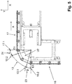
- the transport system 1 denotes a transport system for transporting objects along a transport route TS.
- the transport system 1 comprises at least one hinge-like or chain-like transport element 2 (chain strand) with a multiplicity of transport pallets 3, which are connected to one another in a chain-link-like and articulated manner via chain links 20, namely to the transport element 2, which forms a closed loop and which is connected via a chain wheel 4, for example and at least two more, in the horizontal direction, ie in the direction of the X-axis, or in the vertical direction, ie in the direction of the Y-axis, by means of deflections U1, U2, U3, in the present exemplary embodiment via three further deflections U1, U2, U3 is deflected several times, as shown in the Figures 1 and 2 is shown in more detail.
- the multiple deflected loop SL of the transport element 2 between the chain wheel 4 and the three further deflections U1, U2, U3 is formed in such a way that in the Figure 2
- the top view shown is essentially a rectangle with a free central area MB.
- the transport system 1 thus forms, in particular, a multiple loop SL of the transport element 2 that is deflected in a square shape and has a free central area MB.
- the at least two further deflections U1, U2, U3 can thereby be designed as deflection devices in the form of a deflection curve or deflection roller.
- one of the at least two further deflections U1, U2, U3 is designed as a further chain wheel 4, in particular as a clocked, motor-driven chain wheel.
- the transport system has at least one driven chain wheel 4.
- At least one chain wheel 4 is advantageously provided, which is designed to be driven directly, i.e. gearless, by an electric motor 6, preferably by a torque motor, in at least one transport direction A.
- the chain wheel 4 is mounted in a machine frame 7 with its axis 4.1 in the vertical direction or essentially in the vertical direction, i.e. oriented parallel to the Z axis.
- the multiple deflected loop SL formed by the transport element 2 is thus arranged in a horizontal or essentially horizontal plane, i.e. in the XY plane.
- the transport pallets 3 are each provided with a receptacle 3.11 for receiving objects (e.g. workpieces or other products) that are moved in transport direction A with the rotating transport element 2.
- the transport pallets 3 are each on both sides by means of the Machine frame 7 provided transport pallet guides 30, 31, in particular a first and second transport pallet guide 30, 31, out.
- the transport pallets 3 are guided on both sides between the chain wheel 4 and the first deflections U1 following in the transport direction A by means of the transport pallet guides 30, 31 provided on the machine frame 7.
- the transport pallets 3 are then deflected around the first deflection U1 before the transport pallets 3 are then guided again following in the transport direction A between the first and second deflection U1, U2 on both sides by means of the transport pallet guides 30, 31 provided on the machine frame 7. Analogous to this, the transport pallets 3 are again deflected around the second deflection U2 before the transport pallets 3 are then guided again in the transport direction A between the second and third deflection U2, U3 on both sides by means of the transport pallet guides 30, 31 provided on the machine frame 7 .
- transport pallets 3 are then again deflected around the third deflection U3, before the transport pallets 3 then again following in the transport direction A between the third deflection U3 and the chain wheel 4 are guided on both sides by means of the transport pallet guides 30, 31 provided on the machine frame 7.
- the linear and rectilinear transport pallet guides 30, 31 arranged on the machine frame 7 each extend at least between the chain wheel 4 and the correspondingly adjacent first and third deflection U1, U3, or between the first and second deflection U1, U2 and guides the transport element 2, in particular the individual transport pallets 3 of the transport element 2, at least in this transport section along the transport route TS - that is, in the transport section of the transport route TS in which the transport pallets 3 are out of engagement with the sprocket 4.
- the individual transport pallets 3 are thus guided at least in sections along the transport path TS on both sides by means of the first and second guide devices 30 and 31.
- the transport pallet guides 30, 31 following one another in transport direction A between the chain wheel 4 and / or one of the deflections U1, U2, U3 do not run parallel, but at an angle ⁇ smaller than 180 °, preferably at an angle ⁇ smaller or equal to 120 °, particularly advantageously at an angle ⁇ less than or equal to 90 °.
- the transport pallet guides 30, 31 provided between the chain wheel 4 and the first deflection U1 preferably form an angle ⁇ of approximately 90 ° with the transport pallet guides 30, 31 which follow adjacent in the transport direction A between the first deflection U1 and the second deflection U2.
- the transport pallet guides 30, 31 provided between the first deflection U1 and the second deflection U2 form an angle ⁇ of approximately 90 ° to the transport pallet guides 30, 31 which follow adjacent in the transport direction A between the second deflection U2 and the third deflection U3.
- the transport pallet guides 30, 31 provided between the second deflection U2 and the third deflection U3 form an angle ⁇ of approximately 90 ° to the transport pallet guides 30, 31 which follow adjacent in the transport direction A between the third deflection U3 and the sprocket 4.
- the multiple deflected loop SL of the transport element 2 thus essentially forms a rectangle with a free central area MB between the chain wheel 4 and / or the three further deflections U1, U2, U3 in plan view.
- the transport system 1 thus forms, in particular, a multiple loop SL of the transport element 2 that is deflected in a square shape and has a free central area MB. In the free central area MB, installation space is thus created in which machine tools interacting with the transport system can be arranged.
- the loop formed by the transport element 2 is in the variant of FIG Figures 1 and 2 arranged in a horizontal or substantially horizontal plane, ie in the XY plane. Alternatively, however, it is also possible to arrange the loop formed by the transport element 2 in a vertical or essentially vertical plane, that is to say in an XZ plane.
- the spatial alignment of the loop formed by the transport element 2 is not restricted to any of the exemplary embodiments shown. Rather, the transport element 2 can be arranged in any desired orientation in three-dimensional space.
- the transport pallets 3 form a web-like transport or holding surface on their respective upper sides 3.1, on which, for example, a receptacle 3.11, shown in FIG Figure 1 , is provided and specifically for the reception of objects (eg workpieces or other products) that are moved in the transport direction A with the rotating transport element 2.
- objects eg workpieces or other products
- the sprocket 4 is driven by the drive 6 for the Fig. 1 and 2
- the selected representation is driven clockwise according to the arrow B.
- the sprocket 4 is designed as an eight-part sprocket, which has eight sprocket engagement or driving areas or receptacles 8, which act as driving areas for the chain links of the transport element 2 and preferably at regular angular intervals, i.e. pitch angle TW on a circular path or pitch circle 8.1 around the Rotate axis 4.1 of the chain wheel 4.
- the pocket-like recesses 8 open to the circumference of the chain wheel 4 each form a "chain wheel tooth" between them and have a pitch angle TW which is equal to the chain link length KL of the chain links of the transport element 2, ie the length of each transport pallet 3 or the center distance between two in Transport direction A consecutive joint axes GAS.
- the engagement or driving areas 8 of the sprocket 4 engage, depending on the rotational position, in a first and second guide and bearing device 32, 33 formed on the respective joint axes GAS, which are preferably attached to the respective free ends GAS1, GAS2 of a joint axis GAS of the chain joint 20 of the respective Transport pallets 3 are provided.
- the first and second guide and bearing devices 32, 33 which are provided at the free ends of the respective joint axes GAS of the chain joint 4, engage positively in the engagement or driving areas 8 of the sprocket 4 depending on the rotational position, so that by means of the at least one driven chain wheel 4, a drive movement in the transport direction A can be transmitted to the transport element 2.
- the respective joint axis GAS of the corresponding chain joint 20 can be designed as a one-piece, in particular one-piece joint rod, which extends between its first and second free ends GAS1, GAS2 in such a way that the chain joint 20 has a joint axis running between the first and second guide devices 30, 31 GAS.
- the joint axis GAS forms a joint pin of the chain joint 20 between two adjacent transport pallets 3.
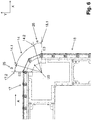
- the transport pallets 3 When the drive 6 is switched on, the transport pallets 3 thus move in the transport direction A on a path of movement, generally designated 10 in the figures, corresponding to the closed, multiply deflected loop SL of the transport element 2, which initially has four circular arc-shaped sections 11, 12, 13 and 14, of which the section 11 between the transport pallet inlet 11.1 and the transport pallet outlet 11.2 of the chain wheel 4, the section 12 between the transport pallet inlet 12.1 and the transport pallet outlet 12.2 of the first deflection U1, the section 13 between the transport pallet inlet 13.1 and the transport pallet outlet 13.2 of the second deflection U2, and the section 14 is formed between the transport pallet inlet 14.1 and the transport pallet outlet 14.2 of the third deflection U3.
- the movement path 10 further comprises four straight sections 15, 16, 17 and 18, which extend in the X direction or Y direction between the chain wheel 4 and / or the deflections U1, U2, U3.
- a transport pallet inlet 15.1 of section 15 and the transport pallet outlet 17.2 of section 17 are located in a horizontal YZ plane that includes axis 4.1 and is designated E2. There is a parallel to level E2 Transport pallet outlet 15.2 of section 15 and the transport pallet inlet 17.1 of section 17 in a plane E1.
- a transport pallet inlet 16.1 of section 16 and the transport pallet outlet 18.2 of section 18 are located in a horizontal YZ plane which includes axis 4.1 and is designated E4.
- a transport pallet outlet 16.2 of section 16 and the transport pallet inlet 18.1 of section 18 are located parallel to plane E4 in a plane E3.
- the plane E2 intersects the plane E4 perpendicularly in the axis 4.1.
- the individual transport pallets 3 are therefore guided on both sides by means of the first and second transport pallet guides 30 and 31 at least in the respective straight sections 15 to 18 along the transport path TS.
- the radial sections 11 to 14 are all of the same length and are oriented to the pitch angle TW of the sprocket 4 or are dimensioned according to this.
- the length of the radial sections 11 to 14 corresponds to the pitch angle TW of the chain wheel 4.
- the transport pallet inlets 11.1, 12.1, 13.1, 14.1, 15.1, 16.1, 17.1, 18.1 and the transport pallet outlets 11.2, 12.2, 13.2, 14.2, 15.2, 16.2 , 17.2, 18.2 are determined by the pitch angle TW of the chain wheel 4.
- Transport pallet inlets 11.1, 12.1, 13.1, 14.1, 15.1, 16.1, 17.1, 18.1 and the transport pallet outlets 11.2, 12.2, 13.2, 14.2, 15.2, 16.2, 17.2, 18.2 can thus be understood to mean that angular position of the rotary movement of the chain wheel 4 at which the respective transport pallet 3 grasped by the chain wheel 4 in a fully form-fitting manner or is released again from the form connection with the chain wheel 4.
- the transport pallet inlets 11.1, 12.1, 13.1, 14.1, 15.1, 16.1, 17.1, 18.1 are each in the direction of rotation B by 22.5 ° with respect to the plane enclosing the axis of the chain wheel 4 and the plane that intersects the straight sections 15, 17 orthogonally E1 and E2 offset in such a way that the transport pallet inlets 11.1, 12.1, 13.1, 14.1, 15.1, 16.1, 17.1, 18.1 each follow in the direction of rotation B on this plane E1 and E2.
- the transport pallet outlets 11.2, 12.2, 13.2, 14.2, 15.2, 16.2, 17.2, 18.2 are offset by 22.5 ° with respect to the plane E3 and E4 which includes the axis 4.1 and which intersects the straight sections 16, 18 orthogonally that the relevant transport pallet outlet is in direction of rotation B in front of level E3 or E4.
- the respective transport pallet inlet 11.1, 12.1, 13.1, 14.1, 15.1, 16.1, 17.1, 18.1 is around an angular range ⁇ , ⁇ of 22.5 degrees offset in the respective direction of rotation B of the sprocket 4, that is, by an angular range ⁇ , ⁇ which corresponds to half the pitch angle TW.
- the movement path 10 also includes sections 19-26, of which the section 19 is between the transport pallet outlet 18.2 and the transport pallet inlet 11.1, the section 20 between the transport pallet outlet 11.2 and the transport pallet inlet 15.1, the section 21 between the transport pallet outlet 15.2 and the transport pallet inlet 12.1 and the Section 22 between the transport pallet outlet 12.2 and the transport pallet inlet 16.1, the section 23 between the transport pallet outlet 16.2 and the transport pallet inlet 13.1, the section 24 between the transport pallet outlet 13.2 and the transport pallet inlet 17.1, the section 25 between the transport pallet outlet 17.2 and the transport pallet inlet 14.1 and the section 26 extend between the transport pallet outlet 14.2 and the transport pallet inlet 18.1.
- the sections 19-26 therefore each extend over the angular range ⁇ , ⁇ of 22.5 ° degrees.
- the sections 19-26 are designed, at least with regard to the horizontal or vertical guidance or the radial guidance (based on the axis 4.1) of the transport pallets 3 in the manner described in more detail below, so that when the chain-like transport element 2 rotates, the polygon effect is completely compensated for (Polygon adjustment) is achieved.
- a compensation curve 28, 28a is assigned to each of the sections 19-26, or a compensation curve 28, 28a is formed in each of the sections 19-26 in the manner described in more detail below.
- the respective compensation curve 28, 28a extends over the respective section 19-26, so that the corresponding compensation curve 28, 28a each extends over an angular range ⁇ , ⁇ which corresponds to half the pitch angle TW of the sprocket meshing or driving regions 8, i.e. over an angle ⁇ , ⁇ of 22.5 °.
- the sections 20, 22, 24 and 26 are basically identical in terms of the course of the transport pallet guide 30, 31 for the transport pallets 3 and each only extend as far as the level E3 or E4.
- the sections 19, 21, 23 and 25 are basically identical in terms of the course of the transport pallet guide 30, 31 for the transport pallets 3 and each only extend as far as the level E1 or E3.
- the Figure 9 exemplarily on the basis of section 24 the course of the compensation curves 28 valid for the sections 20, 22, 24 and 26 and the Figure 10 as an example of section 25, the course of compensation curves 28a valid for sections 19, 21, 23 and 25.
- the respective joint axis GAS of a corresponding chain joint 20 at a first free end GAS1 with the first guide and storage device 32 in the first transport pallet guide 30 and at a second free end GAS2 with the second guide and storage device 33 in the second transport pallet guide 31 out, in particular in two opposite and parallel to the transport direction A and thus preferably perpendicular to the joint axis GAS oriented guide planes FE1, FE2.
- the first and second transport pallet guides 30, 31 in the variant of FIG Figure 8 thus a horizontal guide at least in the straight section 15 to 18 along the transport path TS for the respective joint axis GAS.
- first and second guide and bearing devices 32, 33 each include at least one first and second roller bearing 34 ... 37, which can be designed, for example, as a roller rotatably mounted about the joint axis GAS of the corresponding chain joint 20, and between a first and second guide surfaces 30.1, 30.2 and 31.1, 31.2 of the respective first and second transport pallet guides 30, 31, which lie opposite one another and run parallel to the joint axis GAS.
- first and second roller bearings 34, 35 of the first guide and bearing device 32 are between the opposing guide surfaces 30.1, 30.2 of the first transport pallet guide 30, which run parallel to the joint axis GAS, and the first and second roller bearings 36, 37 of the second guide and bearing device Bearing device 33 guided between the opposite guide surfaces 31.1, 31.2 of the second transport pallet guide 31, which run parallel to the joint axis GAS.
- first and second roller bearings 34 ... 37 of the respective first and second guide and bearing devices 32, 33 between the respective guide surfaces 30.1, 30.2 and 31.1, 31.2 of the corresponding first and second transport pallet guides 30, 31 are parallel to the transport direction A. guided and thus in particular perpendicular to the management levels FE1 and FE2.
- first roller bearing 34 of the first guide and bearing device 32 is provided in the area of the first free end GAS1 so that it can rotate about the joint axis GAS, while the second roller bearing 35 is on the side of the first one facing the second free end GAS2 Roller bearing 34 is also provided rotatably about the hinge axis GAS on this, namely the first roller bearing 34, preferably immediately adjacent to it, for example with a contact fit subsequently.
- the first roller bearing 34 of the first guide and bearing device 32 forms a first outer roller bearing 34 and the second roller bearing 35 forms a second inner roller bearing 35, which extends along the joint axis GAS by approximately the width of the first outer roller bearing 34 is provided offset in the direction of the second free end GAS2 on the joint axis GAS immediately adjacent to the first outer roller bearing 34.
- the first roller bearing 36 of the second guide and bearing device 33 is provided rotatable around the hinge axis GAS in the area of the second free end GAS2, while the second roller bearing 37 is also provided on the side of the first roller bearing 36 facing the first free end GAS1 provided rotatably about the hinge axis GAS, preferably immediately adjacent to the first roller bearing 36, for example connected in a contact-locking manner.
- the first roller bearing 36 of the second guide and bearing device 33 thus forms a first outer roller bearing 36 and the second roller bearing 37 forms a second inner roller bearing 37, which extends along the joint axis GAS by approximately the width of the first outer roller bearing 36 offset in the direction of the first free end GAS1 is provided on the joint axis GAS immediately adjacent to the first outer roller bearing 36.
- the respective first roller bearing 34, 36 of the first and second guide and bearing device 32, 33 are in a first contact section 30.11, 31.11 of the respective first guide surface 30.1, 31.1 and the second roller bearing 35, 37 in a respective second contact section 30.21, 31.21 of the respective second guide surface 30.2, 31.2 abutting and pretensioned to one another, the respective first and second contact sections 30.11 and 30.21 or 31.11 and 31.21 being offset from one another along the hinge axis GAS and provided opposite one another.
- the first roller bearing 34 of the first guide and bearing device 32 is guided in the first transport pallet guide 30 and the first roller bearing 36 in a pretensioned manner on the first contact section 30.11 of the first guide surface 30.1, resting against the second contact section 30.21 of the second guide surface 30.2 of the second guide and bearing device 33 on the first contact section 31.11 of the first guide surface 31.1 in a pretensioned manner against the second roller bearing 37 in the second transport pallet guide 31 in the second transport pallet guide 31 in contact with the second contact section 31.21 of the second guide surface 31.2.
- first roller bearing 34 of the first guide and bearing device 32 is advantageously in contact with the first contact section 30.11 of the first guide surface 30.1 and the second roller bearing 35 in contact with the second contact section 30.21 of the second guide surface 30.2 is guided in the first transport pallet guide 30 in a pretensioned manner compared to the one on the First contact section 31.11 of the first guide surface 31.1, the first roller bearing 36 of the second guide and bearing device 33 and the second roller bearing 37 of the second transport pallet guide 31, which is guided against the second contact section 31.21 of the second guide surface 31.2.
- prestressing forces directed perpendicularly to the hinge axis GAS act in the area of the first guide and storage device 32, respectively, from the first and second contact section 30.11, 30.21 of the first transport pallet guide 30 thus offset along the hinge axis GAS and opposite one another, i.e.
- the first transport pallet guide 30 forms a first guide space FR1 between the first and second guide surfaces 30.1, 30.2, which springs back into the first guide space FR1 in the area of the first and second contact surfaces 30.11, 30.21, i.e.
- first guide roller 34 of the first guide and bearing device 32 rests on the first guide surface 30.1 in the area of the first contact section 30.11 that jumps back into the first guide space FR1 and the second guide roller 35 rests on the second guide surface 30.2 in the area of the second contact section that jumps back into the first guide space FR1 30.21 is applied, while the second guide roller 35 of the first guide and bearing device 32 comes free of the first guide surface 30.1 on the section that does not spring back into the first guide space FR1, i.e. in particular does not contact and the first guide roller 34 comes free of the subsection of the second guide surface 30.2 that does not spring back into the first guide space FR1.
- the second transport pallet guide 31 also forms a second guide space FR2 between the first and second guide surfaces 31.1, 31.2, which springs back into the second guide space FR2 in the area of the first and second contact surfaces 31.11, 31.21, that is to say is stepped in this area, in such a way that that the first guide roller 36 of the second guide and bearing device 33 rests on the first guide surface 31.1 in the area of the first contact section 31.11 that springs back into the second guide space FR2 and the second guide roller 37 on the second guide surface 31.2 in the area of the second that springs back into the second guide space FR2 Contact section 31.21 is applied, while the second guide roller 37 of the second guide and bearing device 33 comes free of the first guide surface 31.1 on the section that does not spring back into the second guide space FR2, i.e. in particular does not contact and the first guide roller 36 does not move from the second en guide space FR2 recessed subsection of the second guide surface 31.2 comes free.
- the hinge axis GAS can be fixed firmly but detachably in a hinge section 20.1 of the respective transport pallet 3 via a holding means 40, for example a grub screw, and prevented from rotating, i.e. a rotation around the longitudinal extent of the hinge axis GAS.
- first roller bearings 34, 36 are only located on the first contact section, 30.11 , 31.11 of the respective first guide surface 30.1, 31.1 and the second roller bearings 35, 37 roll or roll only in contact with the second system section 30.21, 31.21 of the respective second guide surface 30.2, 31.2.
- the Figure 8 an embodiment of the transport pallets 3, in which two further rotatable roller bearings 50, 51 are arranged on the corresponding transport pallet 3 between two adjacent hinge axes GAS on the underside 3.2 opposite the top 3.1, which in the embodiment shown for the vertical guidance of the transport pallets 3 between the first and second transport pallet guides 30, 31 and a further guide rail 52 provided between the two roller bearings 50, 51 are guided.
- the guide rail 52 can be attached to the first and second transport pallet guides 30, 31, in particular to the underside of which, for example, forms a guide device base, arranged, in particular screwed.
- the two roller layers 40, 51 for this purpose lie in particular on the central guide rail 52 extending parallel to the transport direction A and roll or roll on this.
- Figure 7 shows a perspective view of an exemplary embodiment of two exposed and articulated transport pallets 3 of the transport system 1 according to the invention connected to one another via a chain hinge 20.
- the transport pallets 3 have an elastic connecting section 53 in their respective joint section 20.1 on their respective upper sides 3.1, which connects the respective joint section 20.1 of two adjacent transport pallets 3 spanned elastically.
- the connecting section 53 can be arranged, in particular riveted, on the respective upper sides 3.1 of two adjacent transport pallets 3 in an elastically prestressed manner.
- the connecting section 53 can be made from an elastic natural and / or artificial textile fabric.
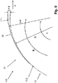
- the first and second transport pallet guides 30, 31 are designed so that at least the first roller bearings 34, 36 of a corresponding joint axis GAS of a chain joint 20 move on a compensation curve 28 or are guided on the compensation curve 28, which corresponds to the Fig. 9 with increasing angular range ⁇ (in the direction of rotation B about the axis 4.1 of the chain wheel 4) from the transport pallet outlet 13.2 radially an increasing distance ⁇ .
- the distance ⁇ increases over the angular range ⁇ after half the pitch angle TW of one of the chain wheels 4 or 2, as seen in the direction of rotation B. half a chain length KL of a transport pallet 3 was passed through.
- the respective compensation curve 28 is therefore formed in the second half of the pitch angle TW, while the compensation curve 28a is formed in the first half of the pitch angle TW, as shown in FIG Figure 10 is shown in more detail.
- R denotes the radius of the pitch circle 8.1, ie the center distance that exists between the axis 4.1 and the joint axis GAS between two transport pallets 3 when this joint axis GAS is located on the sections 11 to 14 of the orbit 10.
- the radial distance between the compensation curve 28 and the axis 4.1 is designated by r24.
- the course of the compensation curves 28a at the sections 19, 21, 23 and 25 is mirror-symmetrical to the compensation curves 28 at the sections 20, 22, 24, 26.
- the compensation curves 28, 28a have the same relative course with respect to the generated distance ⁇ on the respective angular range ⁇ , ⁇ .
- the compensation curve 28 at the sections 20, 22, 24 and 26 is designed mirror-symmetrically to the compensation curve 24a of the sections 19, 21, 23 and 25, specifically in relation to a respective central plane, not shown.
- the course of the compensation curves 28a of the sections 19, 21, 23 and 25 is shown in FIG Figures 10 shown.
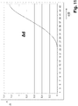
- the fundamental course of the distance ⁇ as a function of the angular range ⁇ or ⁇ , which is independent of the specific dimensions of the transport system 1, is derived from FIG Fig. 11 evident.
- the distance ⁇ initially has a flat inlet, then a steeper but straight rise compared to the inlet, which is then in the area of the outlet, i.e. before reaching the entire angular range ⁇ or ⁇ , flattens again and merges into the transport pallet guide 30, 31 of the section 15 to 18.
- the maximum value of the distance ⁇ is equal to the offset d.
- ⁇ depending on the angular distance ⁇ or ⁇ , has a sine-like, preferably essentially sinus-shaped profile, with a flat inlet in an angular range ⁇ or ⁇ from 0 ° degrees to approximately 8 ° degrees, followed by a Compared to the inlet, it has a steeper but straight rise in an angle range ⁇ or ⁇ between 8 ° degrees to about 19 ° degrees, which is then in the area of the outlet, i.e. before reaching the entire angle range ⁇ or ⁇ , in an angle range ⁇ or ⁇ between 19 ° degrees to 22.5 ° degrees and the transport pallet guide 30, 31 of the section 13 and 14 passes over.
- the essentially sinusoidal course of the difference ⁇ between the compensation curve 28 or 28a and the pitch circle 8.1 on which the sprocket engagement or driving areas 8 move, is independent of the special dimensions of the transport system but typical for the compensation curves 28 and 28a of the transport system according to the invention or for the course of the guides of the sections 19-26, which are each provided between the straight sections 15 to 18 and the chain wheel 4 and / or the deflectors U1, U2, U3 or the transport pallet inlets and outlets there .
- the compensation curves 28 and 28a are always designed so that the compensation curve in no way intersects the pitch circle 8.1, i.e. the distance ⁇ between the compensation curve 28, 28a and the pitch circle 8.1 is zero or greater than zero.
- the compensating curves 28, 28a can be arranged on the corresponding transport pallet guide 30, 31, in particular permanently connected to it.
- the compensating curves 28, 28a can be formed in one piece with the corresponding transport pallet guide 30, 31. It can also be provided that the compensation curves 28, 28a are formed in one piece with the deflections U1, U2, U3.
Abstract
Die Erfindung bezieht sich auf ein Transportsystem zur Beförderung von Gegenständen entlang einer Transportstrecke gemäß Oberbegriff Patentanspruch 1. Das erfindungsgemäße Transportsystem zeichnet sich dadurch aus, dass sich die Ausgleichskurven jeweils über einen Winkelbereich erstrecken, der dem halben Teilungswinkel der Kettenrad- Eingriff oder Mitnahmebereiche entspricht.The invention relates to a transport system for transporting objects along a transport route according to the preamble of patent claim 1. The transport system according to the invention is characterized in that the compensation curves each extend over an angular range that corresponds to half the pitch angle of the sprocket engagement or driving areas.
Description
Die Erfindung bezieht sich auf ein Transportsystem zur Beförderung von Gegenständen entlang einer Transportstrecke sowie auf eine Behandlungsmaschine.The invention relates to a transport system for transporting objects along a transport route and to a treatment machine.
Transportsysteme mit umlaufenden Transportelementen, die von kettenartig miteinander verbundenen Transportpaletten gebildet sind, sind in verschiedenen Ausführungen und für verschiedene Anwendungen bekannt.Transport systems with circulating transport elements, which are formed by transport pallets connected to one another in a chain-like manner, are known in various designs and for various applications.
Auch sind aus dem Stand der Technik bereits Transportsysteme bekannt, bei denen das Transportelement entlang einer Transportstrecke bewegt wird, deren Bewegungsbahn sowohl einen linearen und als auch einen radialen Anteil aufweist. In der Regel ist hierfür zumindest entlang der linearen Bewegung des Transportelementes eine beidseitige Führungseinrichtung der Transportpaletten vorgesehen, die die Transportpaletten parallel der Bewegungsbahn führt.Transport systems are also already known from the prior art in which the transport element is moved along a transport path, the path of which has both a linear and a radial component. As a rule, a guide device on both sides of the transport pallets is provided for this at least along the linear movement of the transport element, which guides the transport pallets parallel to the movement path.
Entlang der Transportstrecke der Transportpaletten eines derartigen Transportsystems erfolgt beispielsweise eine Inspektion und/oder Bearbeitung und/oder Behandlung von Gegenständen oder Werkstücken. Die Behandlung erfolgt dann beispielsweise auf den sich zwischen dem Kettenrad und der Umlenkung erstreckenden Teillängen der Schlaufe bzw. an den dortigen Abschnitten einer Bewegungsbahn, auf der sich die Transportpaletten oder Basiselementen bzw. die Achsen der Kettengelenke zwischen den Transportpaletten bewegen.An inspection and / or processing and / or treatment of objects or workpieces takes place, for example, along the transport path of the transport pallets of such a transport system. The treatment then takes place, for example, on the partial lengths of the loop extending between the chain wheel and the deflection or on the sections of a movement path there on which the transport pallets or base elements or the axes of the chain joints move between the transport pallets.
Nachteilig bei derartigen Transportsystemen ist, dass die Transportpaletten eine bestimmte Länge aufweisen, die dann auch dem Teilungsabstand bzw. dem Teilungswinkel des kettenartigen Transportelementes und des Kettenrades entspricht, und dass insbesondere bei einer größeren Länge bzw. bei einem größeren Teilungsabstand, beispielsweise bei einem Teilungsabstand zwischen 80 mm und 150 mm sich der von Kettenantrieben bekannte Polygoneffekt stark bemerkbar macht, so dass zwar bei einem getakteten Antrieb des Kettenrades grundsätzlich ein Weiterschalten des kettenartigen Transportelementes in jedem Bewegungstakt um einen einzigen Teilungsabstand des Transportelementes bzw. Teilungswinkel des Kettenrades problemlos möglich ist, nicht aber ein Weiterschalten in Schritten größer als der Teilungsabstand, also beispielsweise einer Weiterschaltung mit einer Taktung, die zwei, drei oder vier Teilungsabstände umfasst.The disadvantage of such transport systems is that the transport pallets have a certain length, which then also corresponds to the pitch or the pitch angle of the chain-like transport element and the sprocket, and that in particular with a greater length or with a larger pitch, for example with a pitch between 80 mm and 150 mm, the polygon effect known from chain drives is very noticeable, so that with a clocked drive of the sprocket, the chain-like transport element can be indexed by a single pitch of the transport element or pitch angle of the sprocket without any problems, but not advancing in steps greater than the pitch, so for example a forwarding with a clock that includes two, three or four pitch.
Insbesondere ist wegen des Polygoneffekts erfordert ein getaktetes Weiterschalten in Schritten größer als ein einziger Teilungsabstand mit der notwendigen Genauigkeit das Vorsehen von Ausgleichskurven.In particular, because of the polygon effect, clocked indexing in steps greater than a single pitch requires the provision of compensation curves with the necessary accuracy.
Beispielsweise ist aus der auf die Anmelderin zurückgehenden Druckschrift
Weiterhin ist aus der ebenfalls auf die Anmelderin zurückgehenden Druckschrift
Unabhängig von den speziellen Abmessungen des Transportsystems gemäß der Druckschrift
Aufgabe der Erfindung ist es, ein Transportsystem aufzuzeigen, welches die Nachteile im Stand der Technik vermeidet und insbesondere einen verbesserten Gleichlauf unter gleichzeitiger Vermeidung von negativen dynamischen Bewegungseinflüssen auf das Transportelement während eines Schaltschrittes über mehrere Kettenglieder ermöglicht. Zur Lösung dieser Aufgabe ist ein Transportelement entsprechend dem Patentanspruch 1 ausgebildet. Eine Behandlungsmaschine ist Gegenstand des Patentanspruchs 16. Die Unteransprüche betreffen dabei besonders vorteilhafte Weiterbildungen der Erfindung.The object of the invention is to show a transport system which avoids the disadvantages of the prior art and in particular enables improved synchronization while avoiding negative dynamic movement influences on the transport element during a switching step over several chain links. To solve this problem, a transport element according to
Gemäß einem ersten Aspekt betrifft die vorliegende Erfindung ein Transportsystem zur Beförderung von Gegenständen entlang einer mehrfach umgelenkten Transportstrecke, umfassend wenigstens ein Transportelement, welches aus einer Vielzahl von über Kettengelenke gelenkig miteinander zu einer geschlossenen Schleife verbundenen Kettengliedern besteht und über wenigstens ein Kettenrad in zumindest einer Transportrichtung umlaufend getaktet antreibbar ist, wobei das Transportelement mittels des wenigstens einen Kettenrads sowie zumindest zwei weiteren Umlenkungen als eine geschlossene, mehrfach umgelenkte Schleife mit einem freien Mittelbereich ausgebildet ist, wobei die Kettenglieder als Transportpaletten ausgebildet sind, wobei an dem wenigstens einen Kettenrad in einem vorgegebenen Teilungswinkel Kettenrad-Eingriff- oder Mitnahmebereiche vorgesehen sind, in die an den Kettengelenken der Transportpaletten ausgebildete Führungs- und Lagereinrichtungen bei sich umlaufenden Kettenrad auf jeweils zumindest einem Teilkreis eingreifen, auf dem die Transportpaletten zwischen einem Transportpaletteneinlauf und einem Transportpalettenauslauf zumindest abschnittsweise radial um das wenigstens eine Kettenrad und/oder die wenigstens zwei Umlenkungen geführt sind, wobei zwischen dem wenigstens einem Kettenrad und den entsprechend zugehörigen wenigstens zwei weiteren Umlenkungen jeweils Transportpalettenführungen zum linearen Führen der Mitnahme- und Führungselemente der Transportpaletten jeweils zwischen den mittels des wenigstens einen Kettenrades und der zugehörigen Umlenkung vorgesehen sind, wobei bezogen auf die Transportrichtung jeweils zwischen einem Transportpaletteneinlauf und der entsprechenden linearen Führung mittels der Transportpalettenführungen und zwischen einem Transportpalettenauslauf und der entsprechenden linearen Führung mittels der Transportpalettenführungen jeweils eine Ausgleichkurve vorgesehen ist, entlang der die Führungs- und Lagereinrichtungen der Transportpaletten für einen Polygonausgleich geführt sind, und wobei sich die Ausgleichskurven jeweils über einen Winkelbereich erstrecken, der dem halben Teilungswinkel der Kettenrad- Eingriff oder Mitnahmebereiche entspricht.According to a first aspect, the present invention relates to a transport system for transporting objects along a multiply deflected transport route, comprising at least one transport element, which consists of a plurality of chain links articulated to form a closed loop via chain joints and via at least one chain wheel in at least one transport direction can be driven circumferentially clocked, with the transport element being designed as a closed, multiple deflected loop with a free central area by means of the at least one chain wheel and at least two further deflections, the chain links being designed as transport pallets, with chain wheel engagement or driving areas being provided at a predetermined pitch angle on the at least one chain wheel, in which guide and storage devices formed on the chain joints of the transport pallets engage on at least one pitch circle when the chain wheel rotates, on which the transport pallets are guided between a transport pallet inlet and a transport pallet outlet, at least in sections, radially around the at least one chain wheel and / or the at least two deflections, with transport pallet guides between the at least one chain wheel and the correspondingly associated at least two further deflections for linear guidance of the entrainment and guide elements of the transport pallets are each provided between the means of the at least one chain wheel and the associated deflection, wherein, based on the transport direction, between ei nem transport pallet inlet and the corresponding linear guide by means of the transport pallet guides and between a transport pallet outlet and the corresponding linear guide by means of the transport pallet guides each have a compensation curve, along which the guide and storage facilities of the transport pallets are guided for polygon compensation, and the compensation curves each over extend an angular range which corresponds to half the pitch angle of the sprocket engagement or driving areas.
Besonders vorteilhaft kann durch solcherart ausgebildete Ausgleichskurven eine dynamische Bewegungs- bzw. Lastumkehr auf dem Transportelement vermieden werden. Insbesondere bei Schaltschritten einer Taktung, die über mehrere Kettenglieder, also einem Weiterschalten des kettenartigen Transportelementes mit einem Bewegungstakt größer als der Teilungsabstand, kommt es zu keinen dynamischen Bewegungseinflüsse damit zu keinem erhöhten Verschleiß des Transportelementes insbesondere an den Mitnahme- und Führungselementen. Auch der gewünschte Gleichlauf des Transportelementes wird dabei positiv beeinflusst, was wiederum zu einem im Vergleich zum Stand der Technik ruhigeren Umschalten des Transportsystems während eines Schaltschrittes führt. Weiterhin vorteilhalt weist ein Transportsystem, bei dem die erfindungsgemäß ausgebildeten Ausgleichskurven vorgesehen sind, über die gesamte Transportelementlänge, d. h. über das gesamte Transportelement, sowie vor, während und nach einem getakteten Schaltschritt eine gleichmäße Spannung auf. Ist das Transportelement dabei als Transportkette ausgebildet, so weist die Transportkette also damit in jeder Position und zu einem jedem Zeitpunkt während des getakteten Umschaltschrittes eine gleichmäßige Kettenspannung über die gesamte Kettenlänge auf. Ferner vorteilhaft bildet die mehrfach umlenkte Schleife des Transportelementes zwischen dem Kettenrad und/oder den drei weiteren Umlenkungen in Draufsicht im Wesentlichen ein Rechteck mit einem freien Mittenbereich MB aus. Das Transportsystem bildet damit insbesondere eine mehrfach, in Karreeform umgelenkte Schleife des Transportelementes mit einem freien Mittenbereich MB aus. In dem freien Mittenbereich ist damit Bauraum geschaffen, in dem mit dem Transportsystem zusammenwirkende Werkzeugmaschinen angeordnet werden können.A dynamic movement or load reversal on the transport element can particularly advantageously be avoided by compensating curves designed in this way. In particular, in the case of switching steps of a cycle that takes place over several chain links, i.e. switching the chain-like transport element further with a movement cycle greater than the pitch, there are no dynamic movement influences, so there is no increased wear of the transport element, in particular on the driving and guide elements. The desired synchronism of the transport element is also positively influenced, which in turn leads to a smoother switchover of the transport system during a switching step compared to the prior art. Furthermore, a transport system in which the compensating curves designed according to the invention are provided has an even voltage over the entire transport element length, ie over the entire transport element, as well as before, during and after a clocked switching step. If the transport element is designed as a transport chain, the transport chain thus has a uniform chain tension over the entire chain length in every position and at every point in time during the clocked switching step. Furthermore, the multiple deflected loop of the transport element between the chain wheel and / or the three further deflections in plan view essentially forms a rectangle with a free central area MB. The The transport system thus forms, in particular, a multiple loop of the transport element deflected in a square shape with a free center area MB. In the free central area, installation space is thus created in which machine tools interacting with the transport system can be arranged.
Gemäß einer vorteilhaften Ausführungsvariante kann dabei vorgesehen sein, dass ist die jeweilige Ausgleichkurve bezogen auf die entsprechende Drehrichtung des Kettenrades in der zweiten Hälfte des Teilungswinkels des Kettenrades und die Ausgleichkurve bezogen auf die entsprechende Drehrichtung des Kettenrades in der ersten Hälfte des Teilungswinkels des Kettenrades ausgebildet ist.According to an advantageous embodiment variant, it can be provided that the respective compensation curve is formed in relation to the corresponding direction of rotation of the chain wheel in the second half of the pitch angle of the chain wheel and the compensation curve is configured in relation to the corresponding direction of rotation of the chain wheel in the first half of the pitch angle of the chain wheel.
Gemäß einer weiteren vorteilhaften Ausführungsvariante kann dabei vorgesehen sein, dass die Ausgleichskurven an dem wenigstens einem Kettenrad jeweils vollständig innerhalb eines Winkelbereichs verlaufen, der sich zwischen dem Transportpaletteneinlauf und einer die Achse des betreffenden Kettenrades einschließenden Ebene bzw. der sich zwischen dem Transportpalettenauslauf und dieser die Achse des Kettenrades einschließenden Ebene erstreckt, wobei der Winkelbereich maximal 22,5° Grad beträgt.According to a further advantageous embodiment variant, it can be provided that the compensation curves on the at least one chain wheel each run completely within an angular range that extends between the transport pallet inlet and a plane enclosing the axis of the chain wheel in question, or between the transport pallet outlet and this the axis of the chain wheel enclosing plane extends, the angular range is a maximum of 22.5 ° degrees.
Gemäß einer nochmals weiteren vorteilhaften Ausführungsvariante kann dabei vorgesehen sein, dass die Gesamtlänge jeder Ausgleichskurve größer als der halbe Teilungswinkel der Eingriff- oder Mitnahmebereiche und die halbe Kettengliederlänge des Transportelementes ausgebildet ist, und/oder dass bezogen auf die Transportrichtung die auf den Transportpalettenauslauf des Kettenrades und/oder der entsprechenden Umlenkung folgende Ausgleichskurve einen derartigen Verlauf aufweist, dass ein Abstand zwischen dieser Ausgleichskurve und dem Teilkreis in Drehrichtung des Kettenrades mit zunehmendem Winkelabstand von dem Transportpalettenauslauf zunimmt, und zwar entsprechend einem im Wesentlichen sinus-förmigen Verlauf, dessen Steigung am Anfang und am Ende der Ausgleichskurve kleiner ist als in einem mittleren Bereich.According to yet another advantageous embodiment variant, it can be provided that the total length of each compensation curve is larger than half the pitch angle of the engagement or driving areas and half the chain link length of the transport element, and / or that, based on the transport direction, the transport pallet outlet of the chain wheel and / or the compensation curve following the corresponding deflection has a course such that a distance between this compensation curve and the pitch circle in the direction of rotation of the sprocket increases with increasing angular distance from the transport pallet outlet, namely according to a substantially sinusoidal course, the gradient of which at the beginning and at the The end of the regression curve is smaller than in a middle area.
Gemäß einer nochmals weiteren vorteilhaften Ausführungsvariante kann dabei vorgesehen sein, dass bezogen auf die Transportrichtung die dem Transportpaletteneinlauf des Kettenrades und/oder der entsprechenden Umlenkung vorausgehende Ausgleichskurve einen derartigen Verlauf aufweist, dass der Abstand zwischen dieser Ausgleichskurve und dem Teilkreis entgegen der Drehrichtung des Kettenrades mit zunehmendem Winkelabstand von dem Transportpaletteneinlauf zunimmt, und zwar entsprechend einem im Wesentlichen sinus-förmigen Verlauf, dessen Steigung am Anfang und am Ende der Ausgleichskurve kleiner ist als in einem mittleren Bereich.According to yet another advantageous embodiment variant, it can be provided that, in relation to the transport direction, the compensation curve preceding the transport pallet inlet of the chain wheel and / or the corresponding deflection has a course such that the distance between this compensation curve and the pitch circle counter to the direction of rotation of the chain wheel increases with The angular distance from the transport pallet inlet increases, specifically in accordance with an essentially sinusoidal course, the gradient of which is smaller at the beginning and at the end of the compensation curve than in a central area.
Gemäß einer nochmals weiteren vorteilhaften Ausführungsvariante kann dabei vorgesehen sein, dass sich an das Ende der jeweiligen Ausgleichskurve ein vorzugsweise geradliniger erster Abschnitt der Bewegungsbahn anschließt.According to yet another advantageous embodiment variant, it can be provided that the end of the respective compensation curve is followed by a preferably straight first section of the movement path.
Gemäß einer nochmals weiteren vorteilhaften Ausführungsvariante kann dabei vorgesehen sein, dass die in Transportrichtung jeweils zwischen dem Kettenrad und/oder einer der Umlenkungen aufeinanderfolgenden geradlinigen Abschnitte in einem Winkel kleiner als 180°, vorzugsweise in einem Winkel kleiner oder gleich 120°, besonders vorteilhaft in einem Winkel kleiner oder gleich 90°, vorgesehen sind.According to yet another advantageous embodiment variant, it can be provided that the straight sections following one another in the transport direction between the chain wheel and / or one of the deflections at an angle less than 180 °, preferably at an angle less than or equal to 120 °, particularly advantageously in a Angle less than or equal to 90 ° are provided.
Gemäß einer nochmals weiteren vorteilhaften Ausführungsvariante kann dabei vorgesehen sein, dass die mehrfach umlenkte Schleife des Transportelementes zwischen dem Kettenrad und/oder den weiteren Umlenkungen in Draufsicht im Wesentlichen ein Rechteck mit einem freien Mittenbereich ausgebildet ist.According to yet another advantageous embodiment variant, it can be provided that the multiple deflected loop of the transport element between the chain wheel and / or the further deflections is essentially a rectangle with a free central area in plan view.
Gemäß einer nochmals weiteren vorteilhaften Ausführungsvariante kann dabei vorgesehen sein, dass die Bewegungsbahn der Transportpaletten zusätzlich zu den vier geradlinigen Abschnitten vier kreisbogenförmige Abschnitte jeweils zwischen einem Transportpaletteneinlauf und einem Transportpalettenauslauf des Kettenrades und/oder der Umlenkungen sowie der gekrümmten Abschnitte aufweist, an denen die Ausgleichskurven gebildet sind und von denen die Abschnitte jeweils zwischen einem Transportpalettenauslauf des Kettenrades und/oder Umlenkung und einem Transportpaletteneinlauf eines geradlinigen Abschnitts und die Abschnitte jeweils zwischen einem Transportpalettenauslauf eines geradlinigen Abschnittes und dem Transportpaletteneinlauf des Kettenrades und/oder Umlenkung vorgesehen sind.According to yet another advantageous embodiment variant, it can be provided that the path of movement of the transport pallets, in addition to the four straight sections, has four circular arc-shaped sections between a transport pallet inlet and a transport pallet outlet of the chain wheel and / or the deflections and the curved sections on which the compensating curves are formed and of which the sections are each provided between a transport pallet outlet of the sprocket and / or deflection and a transport pallet inlet of a straight section and the sections are each provided between a transport pallet outlet of a straight section and the transport pallet inlet of the sprocket and / or deflection.
Gemäß einer nochmals weiteren vorteilhaften Ausführungsvariante kann dabei vorgesehen sein, dass wenigstens ein weiteres, als Umlenkung ausgebildetes Kettenrad vorgesehen ist, das getaktet motorisch antreibbar ist.According to yet another advantageous embodiment variant, it can be provided that at least one further chain wheel designed as a deflection is provided, which can be motor-driven in a clocked manner.
Gemäß einer nochmals weiteren vorteilhaften Ausführungsvariante kann dabei vorgesehen sein, dass die Transportpaletten zumindest abschnittsweise entlang der Transportstrecke beidseitig mittels einer ersten und zweiten Führungseinrichtung geführt sind, bei dem ein Kettengelenk jeweils eine zwischen der ersten und zweiten Führungseinrichtung verlaufende Gelenkachse aufweist, die an einem ersten freien Ende mit einer ersten Führungs- und Lagereinrichtung in der ersten Führungseinrichtung und an einem zweiten freien Ende mit einer zweiten Führungs- und Lagereinrichtung in der zweiten Führungseinrichtung geführt ist, wobei die erste und zweite Führungs- und Lagereinrichtung jeweils wenigstens ein erstes und zweites Rollenlager umfassen, die zwischen einer ersten und zweiten, einander gegenüberliegenden und parallel zur Gelenkachse verlaufenden Führungsfläche der jeweiligen Führungseinrichtung geführt sind, wobei das erste Rollerlager in einem ersten Anlageabschnitt der ersten Führungsfläche und das zweite Rollenlager in einem zweiten Anlageabschnitt der zweiten Führungsfläche anliegen und zueinander vorgespannt geführt sind, wobei der erste und zweite Anlageabschnitt entlang der Gelenkachse zueinander versetzt und einander gegenüberliegend sind.According to yet another advantageous embodiment variant, it can be provided that the transport pallets are guided at least in sections along the transport path on both sides by means of a first and second guide device, in which a chain joint has a joint axis running between the first and second guide device, which on a first free The end is guided with a first guide and bearing device in the first guide device and at a second free end with a second guide and bearing device in the second guide device, the first and second guide and bearing device each having at least a first one and second roller bearings, which are guided between a first and second, opposite and parallel to the hinge axis running guide surface of the respective guide device, the first roller bearing in a first contact section of the first guide surface and the second roller bearing in a second contact section of the second guide surface and are guided preloaded with respect to one another, the first and second contact sections being offset from one another along the hinge axis and being opposite one another.
Gemäß einer nochmals weiteren vorteilhaften Ausführungsvariante kann dabei vorgesehen sein, dass die beiden freien Enden der Gelenkachse in der ersten und zweiten Führungseinrichtung in zwei gegenüberliegend und parallel zur Transportrichtung orientierte Führungsebenen geführt sind.According to yet another advantageous embodiment variant, it can be provided that the two free ends of the hinge axis in the first and second guide device are guided in two opposite guide planes oriented parallel to the transport direction.
Gemäß einer nochmals weiteren vorteilhaften Ausführungsvariante kann dabei vorgesehen sein, dass das erste und zweite Rollenlager der ersten Führungs- und Lagereinrichtung um die Gelenkachse drehbar und unmittelbar benachbart an dieser im Bereich des ersten freien Endes vorgesehen sind.According to yet another advantageous embodiment variant, it can be provided that the first and second roller bearings of the first guide and bearing device are rotatable about the joint axis and are provided directly adjacent to this in the region of the first free end.
Gemäß einer nochmals weiteren vorteilhaften Ausführungsvariante kann dabei vorgesehen sein, dass das erste und zweite Rollenlager der zweiten Führungs- und Lagereinrichtung um die Gelenkachse drehbar und unmittelbar benachbart an dieser im Bereich des zweiten freien Endes vorgesehen sind.According to yet another advantageous embodiment variant, it can be provided that the first and second roller bearings of the second guide and bearing device are rotatable about the joint axis and are provided directly adjacent to this in the region of the second free end.
Gemäß einer nochmals weiteren vorteilhaften Ausführungsvariante kann dabei vorgesehen sein, dass das erste Rollenlager der ersten Führungs- und Lagereinrichtung an dem ersten Anlageabschnitt der ersten Führungsfläche anliegend gegen das an dem zweiten Anlageabschnitt der zweiten Führungsfläche anliegende zweite Rollenlager in der ersten Führungseinrichtung vorgespannt geführt ist und das erste Rollenlager der zweiten Führungs- und Lagereinrichtung an dem ersten Anlageabschnitt der ersten Führungsfläche anliegend gegen das an dem zweiten Anlageabschnitt der zweiten Führungsfläche anliegende zweite Rollenlager in der zweiten Führungseinrichtung vorgespannt geführt ist.According to yet another advantageous embodiment variant, it can be provided that the first roller bearing of the first guide and bearing device on the first contact section of the first guide surface is guided in a prestressed manner against the second roller bearing in the first guide device in contact with the second contact section of the second guide surface and that The first roller bearing of the second guide and bearing device is guided in the second guide device in a prestressed manner, resting against the first contact section of the first guide surface, against the second roller bearing resting on the second contact section of the second guide surface.
Gemäß einer nochmals weiteren vorteilhaften Ausführungsvariante kann dabei vorgesehen sein, dass das erste und zweite Rollenlager der ersten Führungs- und Lagereinrichtung vorgespannt gegenüber dem ersten und zweiten Rollenlager der zweiten Führungs- und Lagereinrichtung geführt sind.According to yet another advantageous embodiment variant, it can be provided that the first and second roller bearings of the first guide and bearing device are preloaded with respect to the first and second roller bearings of the second guide and bearing device.
Gemäß einer nochmals weiteren vorteilhaften Ausführungsvariante kann dabei vorgesehen sein, die Ausgleichskurven einstückig mit der entsprechenden Transportpalettenführung ausgebildet sind.According to yet another advantageous embodiment variant, it can be provided that the compensation curves are formed in one piece with the corresponding transport pallet guide.
Gemäß einer nochmals weiteren vorteilhaften Ausführungsvariante kann dabei vorgesehen sein, dass die Ausgleichskurven einstückig mit den Umlenkungen ausgebildet sind.According to yet another advantageous embodiment variant, it can be provided that the compensation curves are designed in one piece with the deflections.
"Teilkreis des Kettenrades" bedeutet im Sinne der Erfindung diejenige Kreisbahn um die Achse des Kettenrades, auf der sich die Kettenrad-Eingriff- oder Mitnahmebereiche bewegen, in die die Mitnahme- und Führungselemente des kettenartigen Transportelementes eingreifen und die beispielsweise von am Umfang des Kettenrades offenen Ausnehmungen zwischen Kettenradzähnen gebildet sind."Partial circle of the chain wheel" within the meaning of the invention means that circular path around the axis of the chain wheel on which the chain wheel engagement or driving areas move, in which the driving and guide elements of the chain-like transport element engage and which are open, for example, on the circumference of the chain wheel Recesses are formed between sprocket teeth.
"Behandlungsmaschinen" im Sinne der vorliegenden Erfindung sind allgemein Maschinen oder Vorrichtungen zum Behandeln von Produkten oder Gegenständen in unterschiedlichster Weise, insbesondere Fertigungs- und/oder Montagemaschinen oder Fertigungs- und/oder Montagevorrichtungen zum maschinellen Bearbeiten und/oder Verarbeiten und/oder Montieren von Bauteilen oder Baugruppen auch in mehreren zeitlich aufeinander folgenden Arbeitsschritten an jeweils einer und/oder an unterschiedlichen Arbeitspositionen oder - stationen."Treatment machines" within the meaning of the present invention are generally machines or devices for treating products or objects in a wide variety of ways, in particular manufacturing and / or assembly machines or manufacturing and / or assembly devices for machining and / or processing and / or assembling components or assemblies also in several successive work steps at one and / or at different work positions or stations.
"Behandlung" im Sinne der Erfindung bedeutet jegliche Behandlung von Produkten oder Gegenständen im weitesten Sinne, insbesondere Verarbeitung und/oder Bearbeitung und/oder Montage usw."Treatment" within the meaning of the invention means any treatment of products or objects in the broadest sense, in particular processing and / or processing and / or assembly, etc.
"Getaktete Bewegung" im Sinne der Erfindung bedeutet eine Bewegung in Schritten mit jeweils anschließender Stillstandsphase, d.h. in Bewegungstakten, von denen jeder eine Bewegungsphase und eine Stillstandsphase aufweist."Clocked movement" within the meaning of the invention means a movement in steps with a subsequent standstill phase, i.e. in movement cycles, each of which has a movement phase and a standstill phase.
"Transportpaletteneinlauf des Kettenrades" ist im Sinne der Erfindung diejenige Winkelstellung der kreisförmigen Bewegungsbahn oder des Teilkreises der Mitnahmebereiche des Kettenrades, an der (Winkelstellung) die Mitnahme- und Führungselemente des kettenartigen Transportelementes erstmals vollständig in jeweils einem Kettenrad-Eingriff- oder Mitnahmebereich des Kettenrades aufgenommen sind bzw. erstmals mit einem Kettenrad-Eingriff- oder Mitnahmebereich vollständig formschlüssig in Eingriff kommen."Transport pallet inlet of the chain wheel" is that angular position of the circular path of movement or of the pitch circle of the driving areas of the chain wheel at which (angular position) the driving and guide elements of the chain-like transport element are completely received for the first time in a chain wheel engagement or driving area of the sprocket are or for the first time come into fully positive engagement with a sprocket engagement or driving area.
"Transportpalettenauslauf des Kettenrades" ist im Sinne der Erfindung derjenige Punkt der kreisförmigen Bewegungsbahn der Kettenrad-Eingriff- oder Mitnahmebereiche des Kettenrades, an dem sich die Mitnahme- und Führungselemente des kettenartigen Transportelementes jeweils wieder aus den Kettenrad-Eingriff- oder Mitnahmebereichen herausbewegen."Transport pallet outlet of the chain wheel" is in the sense of the invention that point of the circular movement path of the chain wheel engagement or driving areas of the Sprocket on which the entrainment and guide elements of the chain-like transport element each move out of the sprocket engagement or entrainment areas.
"Polygonausgleich" bedeutet im Sinne der Erfindung insbesondere auch einen Ausgleich oder eine Kompensation der durch den Polygoneffekt an den Kettenrädern bedingten sich ändernden Transportgeschwindigkeit oder des sich ändernden Transportweges des Transportelementes in der Weise, dass die Transportgeschwindigkeit oder der Transportweg einer getakteten Bewegung des Transportelementes zumindest an Abschnitten der linearen Führung des Transportsystems konstant oder im Wesentlichen konstant ist, an denen auch Arbeitspositionen oder -stationen vorgesehen sind."Polygon compensation" within the meaning of the invention also means in particular a compensation or compensation for the changing transport speed or the changing transport path of the transport element caused by the polygon effect on the sprockets in such a way that the transport speed or the transport path of a clocked movement of the transport element at least Sections of the linear guidance of the transport system is constant or substantially constant, at which work positions or stations are provided.
Der Ausdruck "im Wesentlichen" bzw. "etwa" bedeutet im Sinne der Erfindung Abweichungen von jeweils exakten Werten um +/- 10%, bevorzugt um +/- 5% und/oder Abweichungen in Form von für die Funktion unbedeutenden Änderungen.The expression “essentially” or “approximately” means deviations from exact values by +/- 10%, preferably by +/- 5% and / or deviations in the form of changes that are insignificant for the function.
Weiterbildungen, Vorteile und Anwendungsmöglichkeiten der Erfindung ergeben sich auch aus der nachfolgenden Beschreibung von Ausführungsbeispielen und aus den Figuren. Dabei sind alle beschriebenen und/oder bildlich dargestellten Merkmale für sich oder in beliebiger Kombination grundsätzlich Gegenstand der Erfindung, unabhängig von ihrer Zusammenfassung in den Ansprüchen oder deren Rückbeziehung. Auch wird der Inhalt der Ansprüche zu einem Bestandteil der Beschreibung gemacht.Developments, advantages and possible applications of the invention also emerge from the following description of exemplary embodiments and from the figures. In this case, all of the features described and / or shown in the figures, individually or in any combination, are fundamentally the subject matter of the invention, regardless of how they are summarized in the claims or their reference. The content of the claims is also made part of the description.
Die Erfindung wird im Folgenden anhand der Figuren an einem Ausführungsbeispiel näher erläutert. Es zeigen:
- Fig. 1
- in vereinfachter perspektivischer Darstellung das Transportelement gemäß der Erfindung zur Verwendung bei einer Montage- und/oder Fertigungsmaschine;
- Fig. 2
- in sehr vereinfachter schematischer Darstellung und in Draufsicht das Transportelement der
Fig. 1 ; - Fig.
3bis 6 - in vereinfachter schematischer Darstellung und in Draufsicht die vier Eckbereiche des Transportsystems gemäß
Figur 1 ; - Fig. 7
- in perspektivischer Darstellung zwei gelenkig miteinander verbundene Transportpaletten des Transportsystems der
Fig. 1 ; - Fig. 8
- einen Vertikalschnitt des Transportsystems auf einer Teillänge zwischen den Kettenrädern des Transportsystems;
- Fig. 9
und 10 - jeweils den Verlauf von Ausgleichskurven am Ein- und Auslauf der Umlenkungen, und zwar im Vergleich zu einer Kreisbahn um die Achse des Kettenrades;
- Fig. 11
- in Abhängigkeit von einem Winkelabstand α bzw. β der Abstand Δ zwischen der jeweiligen Ausgleichskurve und einem Teilkreis des Kettenrades.
- Fig. 1
- in a simplified perspective view of the transport element according to the invention for use in an assembly and / or manufacturing machine;
- Fig. 2
- in a very simplified schematic representation and in plan view the transport element of
Fig. 1 ; - Figures 3 to 6
- in a simplified schematic representation and in plan view the four corner areas of the transport system according to FIG
Figure 1 ; - Fig. 7
- in a perspective view two articulated interconnected transport pallets of the transport system of
Fig. 1 ; - Fig. 8
- a vertical section of the transport system on a partial length between the sprockets of the transport system;
- Figures 9 and 10
- the course of compensation curves at the inlet and outlet of the deflections, in comparison to a circular path around the axis of the chain wheel;
- Fig. 11
- Depending on an angular distance α or β, the distance Δ between the respective compensation curve and a pitch circle of the chain wheel.
Für gleiche oder gleich wirkende Elemente der Erfindung werden in den Figuren identische Bezugszeichen verwendet. Ferner werden der Übersichtlichkeit halber nur Bezugszeichen in den einzelnen Figuren dargestellt, die für die Beschreibung der jeweiligen Figur erforderlich sind.Identical reference symbols are used in the figures for elements of the invention that are the same or have the same effect. Furthermore, for the sake of clarity, only reference symbols are shown in the individual figures that are necessary for the description of the respective figure.
Zudem sind zum besseren Verständnis in den Figuren jeweils senkrecht zueinander verlaufende Koordinaten- oder Raumachsen X, Y und Z angegeben, von denen bei der dargestellten Ausführungsform die X-Achse und Y-Achse eine horizontale oder im Wesentlichen horizontale XY-Ebene definieren und von denen die Z-Achse senkrecht zu dieser XY-Ebene orientiert ist.In addition, for better understanding, coordinate or spatial axes X, Y and Z running perpendicular to one another are specified in the figures, of which the X-axis and Y-axis define a horizontal or essentially horizontal XY plane and of which in the embodiment shown the Z-axis is oriented perpendicular to this XY plane.
In den Figuren ist mit 1 ein Transportsystem zur Beförderung von Gegenständen entlang einer Transportstrecke TS bezeichnet. Das Transportsystem 1 umfasst wenigstens ein scharnierband- oder kettenartiges Transportelement 2 (Kettenstrang) mit einer Vielzahl von Transportpaletten 3, die über Kettengelenke 20 kettengliederartig und gelenkig miteinander verbunden sind, und zwar zu dem eine geschlossene Schlaufe bildenden Transportelement 2, welches über beispielsweise ein Kettenrad 4 und wenigstens zwei weitere, in horizontaler Richtung, d.h. in Richtung der X-Achse, bzw. in vertikaler Richtung, d.h. in Richtung der Y-Achse, mittels Umlenkungen U1, U2, U3, im vorliegenden Ausführungsbeispiel über drei weitere Umlenkungen U1, U2, U3 mehrfach umgelenkt geführt ist, wie dies in den
Vorteilhaft ist wenigstens ein Kettenrad 4 vorgesehen, das unmittelbar, d.h. getriebelos durch einen Elektromotor 6, bevorzugt durch einen Torquemotor, in zumindest einer Transportrichtung A umlaufend antreibbar ausgebildet ist. Das Kettenrad 4 ist mit seiner Achse 4.1 in vertikaler Richtung oder im Wesentlichen in vertikaler Richtung, d.h. parallel zur Z-Achse orientiert in einem Maschinenrahmen 7 gelagert.At least one chain wheel 4 is advantageously provided, which is designed to be driven directly, i.e. gearless, by an
Die von dem Transportelement 2 gebildete mehrfach umgelenkte Schleife SL ist somit in einer horizontalen oder im Wesentlichen horizontalen Ebene, d.h. in der XY-Ebene angeordnet. Die Transportpaletten 3 sind jeweils mit einer Aufnahme 3.11 versehen, und zwar für die Aufnahme von Gegenständen (z.B. Werkstücke oder andere Produkte), die mit dem umlaufenden Transportelement 2 in Transportrichtung A bewegt werden.The multiple deflected loop SL formed by the
Außerhalb zumindest des Kettenrades 4, also in dem Transportabschnitt der Transportstrecke TS zwischen dem Kettenrad 4 und den Umlenkungen U1, U2, U3, in dem die Transportpaletten 3 nicht in Eingriff mit dem Kettenrad 4 stehen, sind die Transportpaletten 3 jeweils beidseitig mittels den an dem Maschinenrahmen 7 vorgesehenen Transportpalettenführungen 30, 31, insbesondere einer ersten und zweiten Transportpalettenführung 30, 31, geführt. Mehr im Detail sind dabei die Transportpaletten 3 zwischen dem Kettenrad 4 und der in Transportrichtung A nachfolgenden ersten Umlenkungen U1 beidseitig mittels den am Maschinenrahmen 7 vorgesehenen Transportpalettenführungen 30, 31 geführt. Anschließend werden die Transportpaletten 3 um die erste Umlenkung U1 umlenkt, bevor die Transportpaletten 3 dann wieder in Transportrichtung A folgend zwischen der ersten und der zweiten Umlenkung U1, U2 beidseitig mittels den am Maschinenrahmen 7 vorgesehenen Transportpalettenführungen 30, 31 geführt sind. Analog dazu findet dann wiederum eine Umlenkung der Transportpaletten 3 um die zweite Umlenkung U2 statt, bevor die Transportpaletten 3 dann wieder in Transportrichtung A folgend zwischen der zweiten und der dritten Umlenkung U2, U3 beidseitig mittels den am Maschinenrahmen 7 vorgesehenen Transportpalettenführungen 30, 31 geführt sind. Schließlich findet dann wiederum eine Umlenkung der Transportpaletten 3 um die dritte Umlenkung U3 statt, bevor die Transportpaletten 3 dann wieder in Transportrichtung A folgend zwischen der dritten Umlenkung U3 und dem Kettenrad 4 beidseitig mittels den am Maschinenrahmen 7 vorgesehenen Transportpalettenführungen 30, 31 geführt sind.Outside at least the chain wheel 4, i.e. in the transport section of the transport path TS between the chain wheel 4 and the deflections U1, U2, U3, in which the
In der Ausführungsvariante der
Dabei verlaufen die in Transportrichtung A jeweils zwischen dem Kettenrad 4 und/oder einer der Umlenkungen U1, U2, U3 aufeinanderfolgenden Transportpalettenführungen 30, 31 insbesondere nicht parallel, sondern in einem Winkel µ kleiner als 180°, vorzugsweise in einem Winkel µ kleiner oder gleich 120°, besonders vorteilhaft in einem Winkel µ kleiner oder gleich 90°.The transport pallet guides 30, 31 following one another in transport direction A between the chain wheel 4 and / or one of the deflections U1, U2, U3 do not run parallel, but at an angle μ smaller than 180 °, preferably at an angle μ smaller or equal to 120 °, particularly advantageously at an angle μ less than or equal to 90 °.
Vorzugsweise bilden die zwischen dem Kettenrad 4 und der ersten Umlenkung U1 vorgesehenen Transportpalettenführungen 30, 31 zu den in Transportrichtung A benachbart folgenden Transportpalettenführungen 30, 31 zwischen der ersten Umlenkung U1 und der zweiten Umlenkung U2 einen Winkel µ von näherungsweise 90° aus.The transport pallet guides 30, 31 provided between the chain wheel 4 and the first deflection U1 preferably form an angle μ of approximately 90 ° with the transport pallet guides 30, 31 which follow adjacent in the transport direction A between the first deflection U1 and the second deflection U2.
Ebenfalls vorzugsweise bilden die zwischen der ersten Umlenkung U1 und der zweiten Umlenkung U2 vorgesehenen Transportpalettenführungen 30, 31 zu den in Transportrichtung A benachbart folgenden Transportpalettenführungen 30, 31 zwischen der zweiten Umlenkung U2 und der dritten Umlenkung U3 einen Winkel µ von näherungsweise 90° aus.Likewise preferably, the transport pallet guides 30, 31 provided between the first deflection U1 and the second deflection U2 form an angle μ of approximately 90 ° to the transport pallet guides 30, 31 which follow adjacent in the transport direction A between the second deflection U2 and the third deflection U3.
Ebenfalls vorzugsweise bilden die zwischen der zweiten Umlenkung U2 und der dritten Umlenkung U3 vorgesehenen Transportpalettenführungen 30, 31 zu den in Transportrichtung A benachbart folgenden Transportpalettenführungen 30, 31 zwischen der dritten Umlenkung U3 und dem Kettenrad 4 einen Winkel µ von näherungsweise 90° aus.Likewise preferably, the transport pallet guides 30, 31 provided between the second deflection U2 and the third deflection U3 form an angle μ of approximately 90 ° to the transport pallet guides 30, 31 which follow adjacent in the transport direction A between the third deflection U3 and the sprocket 4.
Damit bildet die mehrfach umlenkte Schleife SL des Transportelementes 2 zwischen dem Kettenrad 4 und/oder den drei weiteren Umlenkungen U1, U2, U3 in Draufsicht im Wesentlichen ein Rechteck mit einem freien Mittenbereich MB aus. Das Transportsystem 1 bildet damit insbesondere eine mehrfach, in Karreeform umgelenkte Schleife SL des Transportelementes 2 mit einem freien Mittenbereich MB aus. In dem freien Mittenbereich MB ist damit Bauraum geschaffen, in dem mit dem Transportsystem zusammenwirkende Werkzeugmaschinen angeordnet werden können.The multiple deflected loop SL of the
Die von dem Transportelement 2 gebildete Schlaufe ist dabei in der Ausführungsvariante der
Die Transportpaletten 3 bilden an ihren jeweiligen Oberseiten 3.1 eine bahnartige Transport- oder Haltefläche aus, an der beispielsweise jeweils eine Aufnahme 3.11, gezeigt in
Bei der dargestellten Ausführungsform wird das Kettenrad 4 durch den Antrieb 6 bei der für die
Das Kettenrad 4 ist dabei als achtteiliges Kettenrad ausgebildet, das acht Kettenrad-Eingriff- oder Mitnahmebereiche oder Aufnahmen 8 aufweist, die als Mitnehmerbereiche für die Kettenglieder des Transportelementes 2 wirken und in vorzugsweise gleichmäßigen Winkelabständen, also Teilungswinkel TW auf einer Kreisbahn oder Teilungskreis 8.1 um die Achse 4.1 des Kettenrades 4 umlaufen. Die zum Umfang des Kettenrades 4 hin offenen taschenartigen Ausnehmungen 8 bilden zwischen sich jeweils einen "Kettenradzahn" und besitzen einen Teilungswinkel TW der gleich der Kettengliedlänge KL der Kettenglieder des Transportelementes 2 ist, d.h. gleich der Länge jeder Transportpalette 3 bzw. des Achsabstandes zwischen zwei in Transportrichtung A aufeinander folgenden Gelenkachsen GAS. Vorzugsweise stellt sich bei einem Kettenrad 4 mit acht Kettenrad- Eingriffs oder Mitnahmebereiche 8 zwischen entsprechend benachbart vorgesehenen Eingriffs- oder Mitnahmebereiche 8 ein Teilungswinkel TW von 45° Grad ein.The sprocket 4 is designed as an eight-part sprocket, which has eight sprocket engagement or driving areas or
Die Eingriff- oder Mitnahmebereiche 8 des Kettenrads 4 greifen dabei drehpositionsabhängig in eine an den jeweiligen Gelenkachsen GAS ausgebildete erste und zweite Führungs- und Lagereinrichtung 32, 33 ein, die vorzugsweise an den jeweiligen freien Enden GAS1, GAS2 einer Gelenkachse GAS des Kettengelenkes 20 der jeweiligen Transportpaletten 3 vorgesehenen sind. In anderen Worten greifen also die ersten und zweiten Führungs- und Lagereinrichtungen 32, 33, die an den freien Enden der jeweiligen Gelenkachsen GAS des Kettengelenkes 4 vorgesehen sind, drehpositionsabhängig formschlüssig in die Eingriff- oder Mitnahmebereiche 8 des Kettenrads 4 ein, so dass mittels des wenigstens einen angetrieben Kettenrades 4 eine Antriebsbewegung in Transportrichtung A auf das Transportelement 2 übertragbar ist. Dabei kann die jeweilige Gelenkachse GAS des entsprechenden Kettengelenkes 20 als einteilige insbesondere einstückige Gelenkstange ausgebildet sein, die sich zwischen ihrem ersten und zweiten freien Ende GAS1, GAS2 derart erstreckt, dass das Kettengelenk 20 jeweils eine zwischen der ersten und zweiten Führungseinrichtung 30, 31 verlaufende Gelenkachse GAS aufweist. Die Gelenkachse GAS bildet dabei einen Gelenkbolzen des Kettengelenkes 20 zwischen zwei benachbarten Transportpaletten 3 aus.The engagement or driving
Bei eingeschaltetem Antrieb 6 bewegen sich die Transportpaletten 3 somit in Transportrichtung A auf einer in den Figuren allgemein mit 10 bezeichneten, der geschlossenen, mehrfach umgelenkten Schleife SL des Transportelementes 2 entsprechenden Bewegungsbahn, die zunächst vier kreisbogenförmige Abschnitte 11, 12, 13 und 14 aufweist, von denen der Abschnitt 11 zwischen dem Transportpaletteneinlauf 11.1 und dem Transportpalettenauslauf 11.2 des Kettenrades 4, der Abschnitt 12 zwischen dem Transportpaletteneinlauf 12.1 und dem Transportpalettenauslauf 12.2 der ersten Umlenkung U1, der Abschnitt 13 zwischen dem Transportpaletteneinlauf 13.1 und dem Transportpalettenauslauf 13.2 der zweiten Umlenkung U2, und der Abschnitt 14 zwischen dem Transportpaletteneinlauf 14.1 und dem Transportpalettenauslauf 14.2 der dritten Umlenkung U3 gebildet ist.When the
Die Bewegungsbahn 10 umfasst weiterhin vier geradlinige Abschnitte 15, 16, 17 und 18, die sich in X-Richtung bzw. Y-Richtung zwischen dem Kettenrad 4 und/oder den Umlenkungen U1, U2, U3 erstrecken.The
Ein Transportpaletteneinlauf 15.1 des Abschnittes 15 sowie der Transportpalettenauslauf 17.2 des Abschnittes 17 befinden in einer die Achse 4.1 einschließenden horizontalen YZ-Ebene, die mit E2 bezeichnet ist. Parallel der Ebene E2 befindet sich ein Transportpalettenauslauf 15.2 des Abschnittes 15 und der Transportpaletteneinlauf 17.1 des Abschnittes 17 in einer die Ebene E1.A transport pallet inlet 15.1 of
Ein Transportpaletteneinlauf 16.1 des Abschnittes 16 sowie der Transportpalettenauslauf 18.2 des Abschnittes 18 befinden in einer die Achse 4.1 einschließenden horizontalen YZ-Ebene, die mit E4 bezeichnet ist. Parallel der Ebene E4 befindet sich ein Transportpalettenauslauf 16.2 des Abschnittes 16 und der Transportpaletteneinlauf 18.1 des Abschnittes 18 in einer die Ebene E3. Die Ebene E2 schneidet dabei die Ebene E4 lotrecht in der Achse 4.1.A transport pallet inlet 16.1 of
Die einzelnen Transportpaletten 3 sind mithin zumindest in dem jeweils geradlinigen Abschnitten 15 bis 18 entlang der Transportstrecke TS beidseitig mittels der ersten und zweiten Transportpalettenführung 30 und 31 geführt.The
Im dem vorliegenden Ausführungsbeispiel sind die radialen Abschnitte 11 bis 14 sämtlich gleich lang ausgebildet und dabei an dem Teilungswinkel TW des Kettenrades 4 orientiert bzw. nach diesem bemessen. Insbesondere entspricht dabei die Länge der radialen Abschnitte 11 bis 14 dem Teilungswinkel TW des Kettenrades 4. Auch die Transportpaletteneinläufe 11.1, 12.1, 13.1, 14.1, 15.1, 16.1, 17.1, 18.1 und die Transportpalettenausläufe 11.2, 12.2, 13.2, 14.2, 15.2, 16.2, 17.2, 18.2 sind durch den Teilungswinkel TW des Kettenrades 4 bestimmt. Unter Transportpaletteneinläufe 11.1, 12.1, 13.1, 14.1, 15.1, 16.1, 17.1, 18.1 und die Transportpalettenausläufe 11.2, 12.2, 13.2, 14.2, 15.2, 16.2, 17.2, 18.2 kann damit diejenige Winkelposition der Drehbewegung des Kettenrades 4 verstanden werden, an der die jeweilige Transportpalette 3 von dem Kettenrad 4 voll formschlüssig erfasst bzw. von dem Formschluss mit dem Kettenrad 4 wieder frei kommt. Bei der dargestellten Ausführungsform sind die Transportpaletteneinläufe 11.1, 12.1, 13.1, 14.1, 15.1, 16.1, 17.1, 18.1 jeweils in Drehrichtung B um 22,5° gegenüber der die Achse des Kettenrades 4 einschließenden sowie die jeweils geraden Abschnitt 15, 17 orthogonal schneidende Ebene E1 bzw. E2 versetzt, und zwar derart, dass die Transportpaletteneinläufe 11.1, 12.1, 13.1, 14.1, 15.1, 16.1, 17.1, 18.1 jeweils in Drehrichtung B auf diese Ebene E1 bzw. E2 folgen. Analog sind die Transportpalettenausläufe 11.2, 12.2, 13.2, 14.2, 15.2, 16.2, 17.2, 18.2 gegenüber der die Achse 4.1 einschließenden sowie die jeweils geraden Abschnitt 16, 18 orthogonal schneidende Ebene E3 bzw. E4 jeweils um 22,5° versetzt, allerdings derart, dass sich der betreffende Transportpalettenauslauf in Drehrichtung B vor der Ebene E3 bzw. E4 befindet.In the present exemplary embodiment, the
Bezogen auf den Teilungswinkel TW eines achteiligen Kettenrades 4von dann 45° Grad, liegt der jeweilige Transportpaletteneinlauf 11.1, 12.1, 13.1, 14.1, 15.1, 16.1, 17.1, 18.1 um einen Winkelbereich α, β von 22,5° Grad versetzt in jeweiliger Drehrichtung B des Kettenrades 4 also um einen Winkelbereich α, β, der dem halben Teilungswinkel TW entspricht.In relation to the pitch angle TW of an axle-part chain wheel 4 of 45 °, the respective transport pallet inlet 11.1, 12.1, 13.1, 14.1, 15.1, 16.1, 17.1, 18.1 is around an angular range α, β of 22.5 degrees offset in the respective direction of rotation B of the sprocket 4, that is, by an angular range α, β which corresponds to half the pitch angle TW.
Die Bewegungsbahn 10 umfasst weiterhin Abschnitte 19 - 26, von denen sich der Abschnitt 19 zwischen dem Transportpalettenauslauf 18.2 und dem Transportpaletteneinlauf 11.1, der Abschnitt 20 zwischen dem Transportpalettenauslauf 11.2 und dem Transportpaletteneinlauf 15.1, der Abschnitt 21 zwischen dem Transportpalettenauslauf 15.2 und dem Transportpaletteneinlauf 12.1 und der Abschnitt 22 zwischen dem Transportpalettenauslauf 12.2 und dem Transportpaletteneinlauf 16.1, der Abschnitt 23 zwischen dem Transportpalettenauslauf 16.2 und dem Transportpaletteneinlauf 13.1, der Abschnitt 24 zwischen dem Transportpalettenauslauf 13.2 und dem Transportpaletteneinlauf 17.1, der Abschnitt 25 zwischen dem Transportpalettenauslauf 17.2 und dem Transportpaletteneinlauf 14.1 und der Abschnitt 26 zwischen dem Transportpalettenauslauf 14.2 und dem Transportpaletteneinlauf 18.1 erstrecken. Mithin erstrecken sich die Abschnitte 19 -26 jeweils über den Winkelbereich α, β von 22,5° Grad.The
Die Abschnitte 19-26 sind zumindest hinsichtlich der horizontalen bzw. vertikalen Führung oder der radialen Führung (bezogen auf die Achse 4.1) der Transportpaletten 3 in der nachstehend noch näher beschriebenen Weise so gestaltet, dass beim Umlauf des kettenartigen Transportelementes 2 ein vollständiger Ausgleich des Polygoneffektes (Polygonausgleich) erreicht wird. Insbesondere ist jedem der Abschnitte 19 - 26 jeweils eine Ausgleichskurve 28, 28a zugeordnet, bzw. in jedem der Abschnitte 19 - 26 eine Ausgleichskurve 28, 28a in der nachstehend noch näher beschriebenen Art und Weise ausgebildet. Insbesondere erstreckt sich die jeweilige Ausgleichskurve 28, 28a über den jeweiligen Abschnitt 19 - 26, so dass sich die entsprechende Ausgleichskurve 28, 28a jeweils über einen Winkelbereich α, β erstreckt, der dem halben Teilungswinkel TW der Kettenrad- Eingriff oder Mitnahmebereiche 8 entspricht, also über einen Winkel α, β von 22,5°.The sections 19-26 are designed, at least with regard to the horizontal or vertical guidance or the radial guidance (based on the axis 4.1) of the
Die Abschnitte 20, 22, 24 und 26 sind hinsichtlich des Verlaufs der Transportpalettenführung 30, 31 für die Transportpaletten 3 grundsätzlich identisch ausgebildet und reichen jeweils nur bis an die Ebene E3 oder E4. Ebenso sind die Abschnitte 19, 21, 23 und 25 hinsichtlich des Verlaufs der Transportpalettenführung 30, 31 für die Transportpaletten 3 grundsätzlich identisch ausgebildet und reichen jeweils nur bis an die Ebene E1 oder E3. Dabei zeigt die
Wie insbesondere in der
Zudem umfassen die erste und zweite Führungs- und Lagereinrichtung 32, 33 hierfür jeweils wenigstens ein erstes und zweites Rollenlager 34...37, das beispielsweise als um die Gelenkachse GAS des entsprechenden Kettengelenks 20 drehbar gelagerte Laufrolle ausgebildet sein kann, und die zwischen einer ersten und zweiten, einander gegenüberliegenden und parallel zur Gelenkachse GAS verlaufenden Führungsfläche 30.1, 30.2 bzw. 31.1, 31.2 der jeweiligen ersten und zweiten Transportpalettenführung 30, 31 geführt sind.In addition, the first and second guide and
Insbesondere sind dabei das erste und zweite Rollenlager 34, 35 der ersten Führungs- und Lagereinrichtung 32 zwischen den einander gegenüberliegenden und parallel zur Gelenkachse GAS verlaufenden Führungsflächen 30.1, 30.2 der ersten Transportpalettenführung 30 und das erste und zweite Rollenlager 36, 37 der zweiten Führungs- und Lagereinrichtung 33 zwischen den einander gegenüberliegenden und parallel zur Gelenkachse GAS verlaufenden Führungsflächen 31.1, 31.2 der zweiten Transportpalettenführung 31 geführt. Somit ist das erste und zweite Rollenlager 34...37 der jeweiligen ersten und zweiten Führungs- und Lagereinrichtung 32, 33 zwischen den jeweiligen Führungsfläche 30.1, 30.2 bzw. 31.1, 31.2 der entsprechenden ersten bzw. zweiten Transportpalettenführung 30, 31 parallel der Transportrichtung A geführt und damit insbesondere lotrecht der Führungsebenen FE1 und FE2.In particular, the first and
Dabei ist insbesondere vorgesehen, dass das erste Rollenlager 34 der ersten Führungs- und Lagereinrichtung 32 im Bereich des ersten freien Endes GAS1 um die Gelenkachse GAS drehbar an dieser vorgesehen ist, während das zweite Rollenlager 35 auf der dem zweiten freien Ende GAS2 zugewandten Seite des ersten Rollenlagers 34 ebenfalls um die Gelenkachse GAS drehbar an dieser vorgesehen ist und zwar dem ersten Rollenlager 34 vorzugsweise unmittelbar benachbart anschließend, beispielweise kontaktschlüssig anschließend. Bezogen auf die Längserstreckung der Gelenkachse GAS bildet das erste Rollenlager 34 der ersten Führungs- und Lagereinrichtung 32 ein erstes äußeres Rollenlager 34 und das zweite Rollenlager 35 ein zweites inneres Rollenlager 35 aus, das entlang der Gelenkachse GAS um näherungsweise die Breite des ersten äußeren Rollenlagers 34 in Richtung des zweiten freien Endes GAS2 versetzt an der Gelenkachse GAS unmittelbar benachbart dem ersten äußeren Rollenlager 34 vorgesehen ist.It is provided in particular that the
Auf Grund des spiegelsymmetrischen Aufbaus ist das erste Rollenlager 36 der zweiten Führungs- und Lagereinrichtung 33 im Bereich des zweiten freien Endes GAS2 um die Gelenkachse GAS drehbar vorgesehen, während das zweite Rollenlager 37 auf der dem ersten freien Ende GAS1 zugewandten Seite des ersten Rollenlagers 36 ebenfalls um die Gelenkachse GAS drehbar vorgesehen und zwar dem ersten Rollenlager 36 vorzugsweise unmittelbar benachbart anschließend, beispielweise kontaktschlüssig anschließend. Bezogen auf die Längserstreckung der Gelenkachse GAS bildet damit das erste Rollenlager 36 der zweiten Führungs- und Lagereinrichtung 33 ein erstes äußeres Rollenlager 36 und das zweite Rollenlager 37 ein zweites inneres Rollenlager 37 aus, das entlang der Gelenkachse GAS um näherungsweise die Breite des ersten äußeren Rollenlagers 36 in Richtung des ersten freien Endes GAS1 versetzt an der Gelenkachse GAS unmittelbar benachbart dem ersten äußeren Rollenlager 36 vorgesehen ist.Due to the mirror-symmetrical structure, the
Dabei sind das jeweilige erste Rollerlager 34, 36 der ersten und zweiten Führungs- und Lagereinrichtung 32, 33 in einem ersten Anlageabschnitt 30.11, 31.11 der jeweiligen ersten Führungsfläche 30.1, 31.1 und das zweite Rollenlager 35, 37 in einem jeweiligen zweiten Anlageabschnitt 30.21, 31.21 der jeweiligen zweiten Führungsfläche 30.2, 31.2 anliegend und zueinander vorgespannt geführt, wobei der jeweilige erste und zweite Anlageabschnitt 30.11 und 30.21 bzw. 31.11 und 31.21 entlang der Gelenkachse GAS zueinander versetzt und einander gegenüberliegend vorgesehen sind.The respective
Vorteilhaft ist das erste Rollenlager 34 der ersten Führungs- und Lagereinrichtung 32 an dem ersten Anlageabschnitt 30.11 der ersten Führungsfläche 30.1 anliegend gegen das an dem zweiten Anlageabschnitt 30.21 der zweiten Führungsfläche 30.2 anliegende zweite Rollenlager 35 in der ersten Transportpalettenführung 30 vorgespannt geführt und das erste Rollenlager 36 der zweiten Führungs- und Lagereinrichtung 33 an dem ersten Anlageabschnitt 31.11 der ersten Führungsfläche 31.1 anliegend gegen das an dem zweiten Anlageabschnitt 31.21 der zweiten Führungsfläche 31.2 anliegende zweite Rollenlager 37 in der zweiten Transportpalettenführung 31 vorgespannt geführt.Advantageously, the
Ferner vorteilhaft ist das erste Rollenlager 34 der ersten Führungs- und Lagereinrichtung 32 an dem ersten Anlageabschnitt 30.11 der ersten Führungsfläche 30.1 anliegend und das an dem zweiten Anlageabschnitt 30.21 der zweiten Führungsfläche 30.2 anliegende zweite Rollenlager 35 in der ersten Transportpalettenführung 30 vorgespannt geführt gegenüber dem an dem ersten Anlageabschnitt 31.11 der ersten Führungsfläche 31.1 anliegenden ersten Rollenlager 36 der zweiten Führungs- und Lagereinrichtung 33 und dem an dem zweiten Anlageabschnitt 31.21 der zweiten Führungsfläche 31.2 anliegend geführten zweiten Rollenlager 37 der zweiten Transportpalettenführung 31.Furthermore, the
Durch die vorgespannte Führung der Gelenkachse GAS in der ersten und zweiten Transportpalettenführung 30, 31 wirken im Bereich der ersten Führungs- und Lagereinrichtung 32 jeweils von dem ersten bzw. zweiten Anlageabschnitt 30.11, 30.21 der ersten Transportpalettenführung 30 lotrecht auf die Gelenkachse GAS gerichtete Vorspannkräfte, die somit entlang der Gelenkachse GAS versetzt und gegenüberliegend, also aufeinander zu gerichtet sind und damit ein Verspannen der ersten Führungs- und Lagereinrichtung 32 entlang der Längserstreckung der Gelenkachse GAS in der ersten Führungseinrichtung 30 gegenüber der in der zweiten Transportpalettenführung 31 geführten zweiten Führungs- und Lagereinrichtung 33 sicherstellen, während im Bereich der zweiten Führungs- und Lagereinrichtung 33 jeweils von dem ersten bzw. zweiten Anlageabschnitt 31.11, 31.21 der zweiten Transportpalettenführung 31 lotrecht auf die Gelenkachse GAS gerichtete Vorspannkräfte, die somit entlang der Gelenkachse GAS versetzt und gegenüberliegend, also aufeinander zu gerichtet sind und damit ein Verspannen zweiten ersten Führungs- und Lagereinrichtung 33 entlang der Längserstreckung der Gelenkachse GAS in der zweiten Transportpalettenführung 31 gegenüber der in der ersten Transportpalettenführung 30 geführten ersten Führungs- und Lagereinrichtung 32 sicherstellen.As a result of the pretensioned guidance of the hinge axis GAS in the first and second transport pallet guides 30, 31, prestressing forces directed perpendicularly to the hinge axis GAS act in the area of the first guide and
Die erste Transportpalettenführung 30 bildet hierfür zwischen der ersten und zweiten Führungsfläche 30.1, 30.2 einen ersten Führungsraum FR1 aus, der im Bereich der ersten und zweiten Anlagefläche 30.11, 30.21 in den ersten Führungsraum FR1 zurückspringt, also in diesem Bereich gestuft ausgebildet ist, derart, dass die erste Führungsrolle 34 der ersten Führungs- und Lagereinrichtung 32 an der ersten Führungsfläche 30.1 im Bereich des in den ersten Führungsraum FR1 zurückspringenden ersten Anlageabschnitt 30.11 anliegt und die zweite Führungsrolle 35 an der zweiten Führungsfläche 30.2 im Bereich des in den ersten Führungsraum FR1 zurückspringenden zweiten Anlageabschnittes 30.21 anliegt, während die zweite Führungsrolle 35 der ersten Führungs- und Lagereinrichtung 32 an dem nicht in ersten den Führungsraum FR1 zurückspringenden Teilabschnitt von der ersten Führungsfläche 30.1 frei kommt, also insbesondere nicht anliegt und die erste Führungsrolle 34 von dem nicht in den ersten Führungsraum FR1 zurückspringenden Teilabschnitt der zweiten Führungsfläche 30.2 freikommt.For this purpose, the first transport pallet guide 30 forms a first guide space FR1 between the first and second guide surfaces 30.1, 30.2, which springs back into the first guide space FR1 in the area of the first and second contact surfaces 30.11, 30.21, i.e. is stepped in this area so that the
Zudem bildet auch die zweite Transportpalettenführung 31 zwischen der ersten und zweiten Führungsfläche 31.1, 31.2 einen zweiten Führungsraum FR2 aus, der im Bereich der ersten und zweiten Anlagefläche 31.11, 31.21 in den zweiten Führungsraum FR2 zurückspringt, also in diesem Bereich gestuft ausgebildet ist, derart, dass die erste Führungsrolle 36 der zweiten Führungs- und Lagereinrichtung 33 an der ersten Führungsfläche 31.1 im Bereich des in den zweiten Führungsraum FR2 zurückspringenden ersten Anlageabschnitt 31.11 anliegt und die zweite Führungsrolle 37 an der zweiten Führungsfläche 31.2 im Bereich des in den zweiten Führungsraum FR2 zurückspringenden zweiten Anlageabschnittes 31.21 anliegt, während die zweite Führungsrolle 37 der zweiten Führungs- und Lagereinrichtung 33 an dem nicht in zweiten den Führungsraum FR2 zurückspringenden Teilabschnitt von der ersten Führungsfläche 31.1 frei kommt, also insbesondere nicht anliegt und die erste Führungsrolle 36 von dem nicht in den zweiten Führungsraum FR2 zurückspringenden Teilabschnitt der zweiten Führungsfläche 31.2 freikommt.In addition, the second
Wird das Transportelement 2 in Transportrichtung A gefördert, so drehen sich die ersten und zweiten Rollenlager 34...37 hierdurch jeweils gegensinnig zueinander um die durch die Gelenkachse GAS gebildete Drehachse. Dabei kann die Gelenkachse GAS über ein Haltemittel 40, beispielsweise eine Madenschraube, fest aber lösbar in einem Gelenkabschnitt 20.1 der jeweiligen Transportpalette 3 fixiert sein und an einer Drehung, also einer Rotation um die Längserstreckung der Gelenkachse GAS, gehindert werden. Die gegensinnige Drehung der jeweiligen ersten Rollenlager 34, 36 zu den jeweiligen zweiten Rollenlager 35, 37 entsteht durch die jeweils gestufte Ausbildung der entsprechenden ersten und zweiten Führungsräume FR1, FR2, so dass sich die ersten Rollenlager 34, 36 nur an dem ersten Anlageabschnitt, 30.11, 31.11 der jeweiligen ersten Führungsfläche 30.1, 31.1 und die zweiten Rollenlager 35, 37 nur an dem zweiten Anlagenabschnitt 30.21, 31.21 der jeweiligen zweiten Führungsfläche 30.2, 31.2 anliegend abrollen bzw. abwälzen.If the
Dabei zeigt die
An den Abschnitten 20, 22, 24 und 26, die sowohl im Bereich des Kettenrades 4 als auch an den Umlenkungen U1, U2, U3 vorgesehen sind, ist in
Bezogen auf jeweils eine Ebene, die die Winkelhalbierende der Drehbewegung des Kettenrades 4 zwischen dem Transportpaletteneinlauf 11.1 und dem Transportpalettenauslauf 11.2 bzw. zwischen dem Transportpaletteneinlauf 12.1 und dem Transportpalettenauslauf 12.2 einschließt und die senkrecht zur XY-Ebene orientiert ist, ist der Verlauf der Ausgleichskurven 28a an den Abschnitten 19, 21, 23 und 25 spiegelsymmetrisch zu den Ausgleichskurven 28 an den Abschnitten 20, 22, 24, 26 ausgebildet. Insbesondere weisen die Ausgleichskurven 28, 28a jedoch denselben relativen Verlauf in Bezug auf den erzeugten Abstand Δ auf dem jeweiligen Winkelbereich α, β auf.In relation to a plane that defines the bisector of the rotational movement of the chain wheel 4 between the transport pallet inlet 11.1 and the transport pallet outlet 11.2 or between the transport pallet inlet 12.1 and the Includes transport pallet outlet 12.2 and which is oriented perpendicular to the XY plane, the course of the compensation curves 28a at the
Weiterhin ist bei der dargestellten Ausführungsform die Ausgleichskurve 28 an den Abschnitten 20, 22, 24 und 26 spiegelsymmetrisch zu der Ausgleichskurve 24a der Abschnitte 19, 21, 23 und 25 ausgeführt, und zwar bezogen auf eine nicht eingezeichnete jeweilige Mittelebene. Der Verlauf der Ausgleichskurven 28a der Abschnitte 19, 21, 23 und 25 ist in den
Der von speziellen Abmessungen des Transportsystems 1 unabhängige grundsätzliche Verlauf des Abstandes Δ in Abhängigkeit vom Winkelbereich α bzw. β ist aus der
Die
Der im Wesentlichen sinus-förmige Verlauf der Differenz Δ zwischen der Ausgleichskurve 28 bzw. 28a und dem Teilkreis 8.1, auf dem sich die Kettenrad-Eingriff- oder Mitnahmebereiche 8 bewegen, ist unabhängig von speziellen Abmessungen des Transportsystems aber typisch für die Ausgleichskurven 28 und 28a des erfindungsgemäßen Transportsystems bzw. für den Verlauf der Führungen der Abschnitte 19 - 26, die jeweils zwischen den geradlinigen Abschnitten 15 bis 18 und den Kettenrad 4 und/oder den Umlenkungen U1, U2, U3 bzw. den dortigen Transportpaletten-Einläufen und Ausläufen vorgesehen sind. Weiterhin sind die Ausgleichskurven 28 und 28a in jedem Fall so ausgebildet, dass die Ausgleichskurve keinesfalls den Teilkreis 8.1 schneidet, d.h. der Abstand Δ zwischen der Ausgleichskurve 28, 28a und dem Teilkreis 8.1 Null oder größer als Null ist.The essentially sinusoidal course of the difference Δ between the
Gemäß einer bevorzugten Ausführungsvariante können die Ausgleichskurven 28, 28a an der entsprechenden Transportpalettenführung 30, 31 angeordnet, insbesondere mit dieser fest verbunden, sein. Alternativ können die können die Ausgleichskurven 28, 28a einstückig mit der entsprechenden Transportpalettenführung 30, 31 ausgebildet sein. Dabei kann auch vorgesehen sein, dass die Ausgleichskurven 28, 28a einstückig mit den Umlenkungen U1, U2, U3 ausgebildet sind.According to a preferred embodiment variant, the compensating
Die Erfindung wurde voranstehend an Ausführungsbeispielen beschrieben. Es versteht sich, dass zahlreiche Änderungen sowie Abwandlungen möglich sind, ohne dass dadurch der der Erfindung zugrundeliegende Erfindungsgedanke verlassen wird.The invention was described above using exemplary embodiments. It goes without saying that numerous changes and modifications are possible without departing from the inventive concept on which the invention is based.
- 11
- TransportsystemTransport system
- 22
- Kettenartigen TransportelementChain-like transport element
- 33
- TransportpaletteTransport pallet
- 3.13.1
- OberseiteTop
- 3.113.11
- Aufnahmeadmission
- 3.23.2
- Unterseitebottom
- 44th
- KettenradSprocket
- 4.14.1
- Achse des KettenradesAxis of the sprocket
- 66th
- Antriebsrotor (Torquemotor)Drive rotor (torque motor)
- 77th
- MaschinengestelltMachine-driven
- 88th
- Kettenrad-Eingriff- oder Mitnahmebereich oder KettenradausnehmungSprocket engagement or driving area or sprocket recess
- 8.18.1
-
Teilkreis der Ausnehmungen 8Partial circle of the
recesses 8 - 99
- Produkt oder WerkstückProduct or workpiece
- 1010
-
Bewegungsbahn der Transportpaletten 3Movement path of the
transport pallets 3 - 11-2611-26
-
Abschnitte der Bewegungsbahn 10Sections of the
movement path 10
- 2020th
- KettengelenkChain joint
- 20.120.1
- GelenkabschnittJoint section
- 28, 28a28, 28a
- AusgleichskurveBest fit curve
- 3030th
- erste Transportpalettenführungfirst transport pallet guide
- 30.130.1
- erste Führungsflächefirst guide surface
- 30.1111/30
- erster Anlageabschnittfirst section
- 30.230.2
- zweite Führungsflächesecond guide surface
- 30.2130.21
- zweiter Anlageabschnittsecond plant section
- 3131
- zweite Transportpalettenführungsecond transport pallet guide
- 31.131.1
- erste Führungsflächefirst guide surface
- 31.1111/31
- erster Anlageabschnittfirst section
- 31.231.2
- zweite Führungsflächesecond guide surface
- 31.2131.21
- zweiter Anlageabschnittsecond plant section
- 3232
- erste Führungs- und Lagereinrichtungfirst guide and storage facility
- 3333
- zweite Führungs- und Lagereinrichtungsecond guide and storage facility
- 34...3734 ... 37
- RollenlagerRoller bearings
- 4040
- HaltemittelHolding means
- 5050
- RollenlagerRoller bearings
- 5151
- RollenlagerRoller bearings
- 5252
- FührungsschieneGuide rail
- AA.
-
Transportrichtung der Transportpaletten 3Transport direction of the
transport pallets 3 - BCBC
-
Drehrichtung der Kettenräder 4 und 5Direction of rotation of
sprockets 4 and 5 - E1-E4E1-E4
- Ebenelevel
- KLKL
- KettengliedlängeChain link length
- dd
- VersatzOffset
- RR.
- Radius des Teilkreises 8.1Radius of the pitch circle 8.1
- r24r24
-
radiale Abstand der Ausgleichskurve 24radial distance of the
compensation curve 24 - r24ar24a
- radiale Abstand der Ausgleichskurve 24aradial distance of the compensation curve 24a
- ΔΔ
-
Abstand zwischen Ausgleichskurve 24/24a und Teilkreis 8.1Distance between
compensation curve 24 / 24a and pitch circle 8.1 - GASGAS
- GelenkachseJoint axis
- GAS1GAS1
- erstes freies Endefirst free end
- GAS2GAS2
- zweites freies Endesecond free end
- FE1FE1
- erste Führungsebenefirst management level
- FE2FE2
- zweite Führungsebenesecond management level
- FR1FR1
- erster Führungsraumfirst leadership room
- FR2FR2
- zweiter Führungsraumsecond leadership room
- TSTS
- TransportstreckeTransport route
- TFTF
- TransportflächeTransport area
- MBMB
- MittenbereichMiddle area
- SLSL
- Schleifeloop
Claims (16)
dadurch gekennzeichnet,
dass das Transportsystem (1) nach einem der vorherigen Ansprüche ausgebildet ist.Treatment machine, for example an assembly and / or manufacturing machine, with a transport system (1) with transport pallets (3) for receiving products or objects (9), the transport pallets (3) moving, preferably clocked, on a self-contained movement path (10) are moved, and work stations are provided on the movement path (10),
characterized,
that the transport system (1) is designed according to one of the preceding claims.
Applications Claiming Priority (1)
| Application Number | Priority Date | Filing Date | Title |
|---|---|---|---|
| DE102019118663.3A DE102019118663A1 (en) | 2019-07-10 | 2019-07-10 | Transport system and treatment machine with such a transport system |
Publications (2)
| Publication Number | Publication Date |
|---|---|
| EP3763639A1 true EP3763639A1 (en) | 2021-01-13 |
| EP3763639B1 EP3763639B1 (en) | 2023-02-22 |
Family
ID=70802767
Family Applications (1)
| Application Number | Title | Priority Date | Filing Date |
|---|---|---|---|
| EP20176002.2A Active EP3763639B1 (en) | 2019-07-10 | 2020-05-22 | Transport system and treatment machine with such a transport system |
Country Status (7)
| Country | Link |
|---|---|
| EP (1) | EP3763639B1 (en) |
| DE (1) | DE102019118663A1 (en) |
| DK (1) | DK3763639T3 (en) |
| ES (1) | ES2940789T3 (en) |
| FI (1) | FI3763639T3 (en) |
| HU (1) | HUE061447T2 (en) |
| PL (1) | PL3763639T3 (en) |
Cited By (1)
| Publication number | Priority date | Publication date | Assignee | Title |
|---|---|---|---|---|
| CN113911700A (en) * | 2021-08-31 | 2022-01-11 | 广东文灿压铸科技有限公司 | Handling system of car gearbox shell |
Families Citing this family (1)
| Publication number | Priority date | Publication date | Assignee | Title |
|---|---|---|---|---|
| DE102021107189A1 (en) | 2021-03-23 | 2022-09-29 | Taktomat Kurvengesteuerte Antriebssysteme Gmbh | transport system |
Citations (8)
| Publication number | Priority date | Publication date | Assignee | Title |
|---|---|---|---|---|
| FR2546142A1 (en) * | 1983-05-17 | 1984-11-23 | Metanic Sa | Conveyor-belt drive device, particularly for a heat-treatment furnace |
| DE3542198A1 (en) * | 1985-11-29 | 1987-06-04 | Elastogran Masch Bau | Double plate belt for the continuous production of laminated foam blocks |
| DE3990012C1 (en) * | 1988-01-07 | 2000-11-09 | Walter Sticht | Installation for machining and/or assembling components |
| DE102012104213A1 (en) | 2012-05-15 | 2013-11-21 | Taktomat Kurvengesteuerte Antriebssysteme Gmbh | Transportation system for assembly/manufacturing machine to e.g. process products or objects, has motor designed as torque motor, where clocked movement is controlled and regulated regarding position of transportation element or palettes |
| DE102013206961A1 (en) * | 2013-04-17 | 2014-10-23 | Bielomatik Leuze Gmbh + Co. Kg | Device for the linear transport of flat objects |
| DE102015107113A1 (en) | 2015-01-20 | 2016-07-21 | Taktomat Kurvengesteuerte Antriebssysteme Gmbh | Transport system and treatment machine with such a transport system |
| WO2016140564A1 (en) * | 2015-02-05 | 2016-09-09 | Rexnord Flattop Europe B.V. | Chain conveyor with adjustable distance between shafts |
| DE102016108765A1 (en) * | 2016-05-12 | 2017-11-16 | Taktomat Kurvengesteuerte Antriebssysteme Gmbh | transport system |
Family Cites Families (3)
| Publication number | Priority date | Publication date | Assignee | Title |
|---|---|---|---|---|
| DE102011018942B4 (en) * | 2011-03-15 | 2018-10-18 | Taktomat Kurvengesteuerte Antriebssysteme Gmbh | Transport route for treatment machines and treatment machine |
| DE102011018943A1 (en) * | 2011-03-15 | 2012-09-20 | Taktomat Kurvengesteuerte Antriebssysteme Gmbh | Transport system for processing machine, has transport element whose rotational angle is adjusted with respect to rotational angle of output shaft of gearbox |
| DE102018100409B4 (en) * | 2018-01-10 | 2021-10-21 | Taktomat Kurvengesteuerte Antriebssysteme Gmbh | Transport system and treatment machine with such a transport system |
-
2019
- 2019-07-10 DE DE102019118663.3A patent/DE102019118663A1/en not_active Ceased
-
2020
- 2020-05-22 DK DK20176002.2T patent/DK3763639T3/en active
- 2020-05-22 PL PL20176002.2T patent/PL3763639T3/en unknown
- 2020-05-22 FI FIEP20176002.2T patent/FI3763639T3/en active
- 2020-05-22 HU HUE20176002A patent/HUE061447T2/en unknown
- 2020-05-22 EP EP20176002.2A patent/EP3763639B1/en active Active
- 2020-05-22 ES ES20176002T patent/ES2940789T3/en active Active
Patent Citations (8)
| Publication number | Priority date | Publication date | Assignee | Title |
|---|---|---|---|---|
| FR2546142A1 (en) * | 1983-05-17 | 1984-11-23 | Metanic Sa | Conveyor-belt drive device, particularly for a heat-treatment furnace |
| DE3542198A1 (en) * | 1985-11-29 | 1987-06-04 | Elastogran Masch Bau | Double plate belt for the continuous production of laminated foam blocks |
| DE3990012C1 (en) * | 1988-01-07 | 2000-11-09 | Walter Sticht | Installation for machining and/or assembling components |
| DE102012104213A1 (en) | 2012-05-15 | 2013-11-21 | Taktomat Kurvengesteuerte Antriebssysteme Gmbh | Transportation system for assembly/manufacturing machine to e.g. process products or objects, has motor designed as torque motor, where clocked movement is controlled and regulated regarding position of transportation element or palettes |
| DE102013206961A1 (en) * | 2013-04-17 | 2014-10-23 | Bielomatik Leuze Gmbh + Co. Kg | Device for the linear transport of flat objects |
| DE102015107113A1 (en) | 2015-01-20 | 2016-07-21 | Taktomat Kurvengesteuerte Antriebssysteme Gmbh | Transport system and treatment machine with such a transport system |
| WO2016140564A1 (en) * | 2015-02-05 | 2016-09-09 | Rexnord Flattop Europe B.V. | Chain conveyor with adjustable distance between shafts |
| DE102016108765A1 (en) * | 2016-05-12 | 2017-11-16 | Taktomat Kurvengesteuerte Antriebssysteme Gmbh | transport system |
Cited By (1)
| Publication number | Priority date | Publication date | Assignee | Title |
|---|---|---|---|---|
| CN113911700A (en) * | 2021-08-31 | 2022-01-11 | 广东文灿压铸科技有限公司 | Handling system of car gearbox shell |
Also Published As
| Publication number | Publication date |
|---|---|
| DE102019118663A1 (en) | 2021-01-14 |
| ES2940789T3 (en) | 2023-05-11 |
| DK3763639T3 (en) | 2023-03-27 |
| EP3763639B1 (en) | 2023-02-22 |
| FI3763639T3 (en) | 2023-04-03 |
| PL3763639T3 (en) | 2023-07-10 |
| HUE061447T2 (en) | 2023-07-28 |
Similar Documents
| Publication | Publication Date | Title |
|---|---|---|
| DE102018100409B4 (en) | Transport system and treatment machine with such a transport system | |
| EP0170773B1 (en) | Rack and pinion drive for the generation of a relative motion between two machine parts guided relative to one another | |
| DE3990012C1 (en) | Installation for machining and/or assembling components | |
| DE3629367C2 (en) | ||
| DE102015107113B4 (en) | Transport system and treatment machine with such a transport system | |
| EP1878674B1 (en) | Chain link for the conveyor chain of a machine tool and a double end profiler with chains having such chain links | |
| EP0340639A1 (en) | Assembling plant | |
| EP3954634B1 (en) | Transport system and treatment machine with such a transport system | |
| DE102012104213B4 (en) | Transport system for treatment machines and treatment machine | |
| EP3763639A1 (en) | Transport system and treatment machine with such a transport system | |
| DE4211658A1 (en) | Feed device for boards | |
| DE102011018943A1 (en) | Transport system for processing machine, has transport element whose rotational angle is adjusted with respect to rotational angle of output shaft of gearbox | |
| DE20319366U1 (en) | Continuous grinding machine for processing a flat workpiece surface | |
| DE102011018942B4 (en) | Transport route for treatment machines and treatment machine | |
| DE19608844B4 (en) | robot | |
| DE3013410A1 (en) | Tool carrier with two parallel rails - has three radially disposed rollers in star pattern in movable support | |
| DE102016108765B4 (en) | Transportation system | |
| EP3721100B1 (en) | Connection assembly | |
| DE202019005870U1 (en) | Transport system and treatment machine with such a transport system | |
| DE202017004877U1 (en) | Parallel gripper with biaxial support structure | |
| DE19532391A1 (en) | Conveyor drive head with return end | |
| DE102016010092B3 (en) | turntable | |
| EP1980359A1 (en) | Adjustment unit | |
| EP0623533A1 (en) | Method and conveyor device for conveying workpiece-carriers | |
| EP0615405B1 (en) | Machining and assembling system for small objects |
Legal Events
| Date | Code | Title | Description |
|---|---|---|---|
| PUAI | Public reference made under article 153(3) epc to a published international application that has entered the european phase |
Free format text: ORIGINAL CODE: 0009012 |
|
| STAA | Information on the status of an ep patent application or granted ep patent |
Free format text: STATUS: THE APPLICATION HAS BEEN PUBLISHED |
|
| AK | Designated contracting states |
Kind code of ref document: A1 Designated state(s): AL AT BE BG CH CY CZ DE DK EE ES FI FR GB GR HR HU IE IS IT LI LT LU LV MC MK MT NL NO PL PT RO RS SE SI SK SM TR |
|
| AX | Request for extension of the european patent |
Extension state: BA ME |
|
| STAA | Information on the status of an ep patent application or granted ep patent |
Free format text: STATUS: REQUEST FOR EXAMINATION WAS MADE |
|
| 17P | Request for examination filed |
Effective date: 20210617 |
|
| RBV | Designated contracting states (corrected) |
Designated state(s): AL AT BE BG CH CY CZ DE DK EE ES FI FR GB GR HR HU IE IS IT LI LT LU LV MC MK MT NL NO PL PT RO RS SE SI SK SM TR |
|
| GRAP | Despatch of communication of intention to grant a patent |
Free format text: ORIGINAL CODE: EPIDOSNIGR1 |
|
| STAA | Information on the status of an ep patent application or granted ep patent |
Free format text: STATUS: GRANT OF PATENT IS INTENDED |
|
| INTG | Intention to grant announced |
Effective date: 20221130 |
|
| GRAS | Grant fee paid |
Free format text: ORIGINAL CODE: EPIDOSNIGR3 |
|
| GRAA | (expected) grant |
Free format text: ORIGINAL CODE: 0009210 |
|
| STAA | Information on the status of an ep patent application or granted ep patent |
Free format text: STATUS: THE PATENT HAS BEEN GRANTED |
|
| AK | Designated contracting states |
Kind code of ref document: B1 Designated state(s): AL AT BE BG CH CY CZ DE DK EE ES FI FR GB GR HR HU IE IS IT LI LT LU LV MC MK MT NL NO PL PT RO RS SE SI SK SM TR |
|
| REG | Reference to a national code |
Ref country code: GB Ref legal event code: FG4D Free format text: NOT ENGLISH |
|
| REG | Reference to a national code |
Ref country code: CH Ref legal event code: EP |
|
| REG | Reference to a national code |
Ref country code: DE Ref legal event code: R096 Ref document number: 502020002554 Country of ref document: DE |
|
| REG | Reference to a national code |
Ref country code: AT Ref legal event code: REF Ref document number: 1549385 Country of ref document: AT Kind code of ref document: T Effective date: 20230315 Ref country code: IE Ref legal event code: FG4D Free format text: LANGUAGE OF EP DOCUMENT: GERMAN |
|
| REG | Reference to a national code |
Ref country code: DK Ref legal event code: T3 Effective date: 20230323 |
|
| REG | Reference to a national code |
Ref country code: NL Ref legal event code: FP |
|
| REG | Reference to a national code |
Ref country code: SE Ref legal event code: TRGR |
|
| REG | Reference to a national code |
Ref country code: ES Ref legal event code: FG2A Ref document number: 2940789 Country of ref document: ES Kind code of ref document: T3 Effective date: 20230511 |
|
| REG | Reference to a national code |
Ref country code: LT Ref legal event code: MG9D |
|
| P01 | Opt-out of the competence of the unified patent court (upc) registered |
Effective date: 20230530 |
|
| REG | Reference to a national code |
Ref country code: HU Ref legal event code: AG4A Ref document number: E061447 Country of ref document: HU |
|
| PG25 | Lapsed in a contracting state [announced via postgrant information from national office to epo] |
Ref country code: RS Free format text: LAPSE BECAUSE OF FAILURE TO SUBMIT A TRANSLATION OF THE DESCRIPTION OR TO PAY THE FEE WITHIN THE PRESCRIBED TIME-LIMIT Effective date: 20230222 Ref country code: PT Free format text: LAPSE BECAUSE OF FAILURE TO SUBMIT A TRANSLATION OF THE DESCRIPTION OR TO PAY THE FEE WITHIN THE PRESCRIBED TIME-LIMIT Effective date: 20230622 Ref country code: NO Free format text: LAPSE BECAUSE OF FAILURE TO SUBMIT A TRANSLATION OF THE DESCRIPTION OR TO PAY THE FEE WITHIN THE PRESCRIBED TIME-LIMIT Effective date: 20230522 Ref country code: LV Free format text: LAPSE BECAUSE OF FAILURE TO SUBMIT A TRANSLATION OF THE DESCRIPTION OR TO PAY THE FEE WITHIN THE PRESCRIBED TIME-LIMIT Effective date: 20230222 Ref country code: LT Free format text: LAPSE BECAUSE OF FAILURE TO SUBMIT A TRANSLATION OF THE DESCRIPTION OR TO PAY THE FEE WITHIN THE PRESCRIBED TIME-LIMIT Effective date: 20230222 Ref country code: HR Free format text: LAPSE BECAUSE OF FAILURE TO SUBMIT A TRANSLATION OF THE DESCRIPTION OR TO PAY THE FEE WITHIN THE PRESCRIBED TIME-LIMIT Effective date: 20230222 |
|
| PGFP | Annual fee paid to national office [announced via postgrant information from national office to epo] |
Ref country code: NL Payment date: 20230519 Year of fee payment: 4 Ref country code: IT Payment date: 20230531 Year of fee payment: 4 Ref country code: FR Payment date: 20230526 Year of fee payment: 4 Ref country code: DK Payment date: 20230524 Year of fee payment: 4 Ref country code: DE Payment date: 20230530 Year of fee payment: 4 Ref country code: CZ Payment date: 20230515 Year of fee payment: 4 Ref country code: CH Payment date: 20230602 Year of fee payment: 4 |
|
| PG25 | Lapsed in a contracting state [announced via postgrant information from national office to epo] |
Ref country code: IS Free format text: LAPSE BECAUSE OF FAILURE TO SUBMIT A TRANSLATION OF THE DESCRIPTION OR TO PAY THE FEE WITHIN THE PRESCRIBED TIME-LIMIT Effective date: 20230622 Ref country code: GR Free format text: LAPSE BECAUSE OF FAILURE TO SUBMIT A TRANSLATION OF THE DESCRIPTION OR TO PAY THE FEE WITHIN THE PRESCRIBED TIME-LIMIT Effective date: 20230523 |
|
| PGFP | Annual fee paid to national office [announced via postgrant information from national office to epo] |
Ref country code: SE Payment date: 20230519 Year of fee payment: 4 Ref country code: PL Payment date: 20230512 Year of fee payment: 4 Ref country code: HU Payment date: 20230524 Year of fee payment: 4 Ref country code: FI Payment date: 20230523 Year of fee payment: 4 |
|
| PGFP | Annual fee paid to national office [announced via postgrant information from national office to epo] |
Ref country code: BE Payment date: 20230519 Year of fee payment: 4 |
|
| PG25 | Lapsed in a contracting state [announced via postgrant information from national office to epo] |
Ref country code: SM Free format text: LAPSE BECAUSE OF FAILURE TO SUBMIT A TRANSLATION OF THE DESCRIPTION OR TO PAY THE FEE WITHIN THE PRESCRIBED TIME-LIMIT Effective date: 20230222 Ref country code: RO Free format text: LAPSE BECAUSE OF FAILURE TO SUBMIT A TRANSLATION OF THE DESCRIPTION OR TO PAY THE FEE WITHIN THE PRESCRIBED TIME-LIMIT Effective date: 20230222 Ref country code: EE Free format text: LAPSE BECAUSE OF FAILURE TO SUBMIT A TRANSLATION OF THE DESCRIPTION OR TO PAY THE FEE WITHIN THE PRESCRIBED TIME-LIMIT Effective date: 20230222 |
|
| PGFP | Annual fee paid to national office [announced via postgrant information from national office to epo] |
Ref country code: ES Payment date: 20230726 Year of fee payment: 4 |
|
| REG | Reference to a national code |
Ref country code: DE Ref legal event code: R097 Ref document number: 502020002554 Country of ref document: DE |
|
| PG25 | Lapsed in a contracting state [announced via postgrant information from national office to epo] |
Ref country code: SK Free format text: LAPSE BECAUSE OF FAILURE TO SUBMIT A TRANSLATION OF THE DESCRIPTION OR TO PAY THE FEE WITHIN THE PRESCRIBED TIME-LIMIT Effective date: 20230222 |
|
| PLBE | No opposition filed within time limit |
Free format text: ORIGINAL CODE: 0009261 |
|
| STAA | Information on the status of an ep patent application or granted ep patent |
Free format text: STATUS: NO OPPOSITION FILED WITHIN TIME LIMIT |
|
| PG25 | Lapsed in a contracting state [announced via postgrant information from national office to epo] |
Ref country code: MC Free format text: LAPSE BECAUSE OF FAILURE TO SUBMIT A TRANSLATION OF THE DESCRIPTION OR TO PAY THE FEE WITHIN THE PRESCRIBED TIME-LIMIT Effective date: 20230222 |
|
| 26N | No opposition filed |
Effective date: 20231123 |
|
| PG25 | Lapsed in a contracting state [announced via postgrant information from national office to epo] |
Ref country code: SI Free format text: LAPSE BECAUSE OF FAILURE TO SUBMIT A TRANSLATION OF THE DESCRIPTION OR TO PAY THE FEE WITHIN THE PRESCRIBED TIME-LIMIT Effective date: 20230222 Ref country code: MC Free format text: LAPSE BECAUSE OF FAILURE TO SUBMIT A TRANSLATION OF THE DESCRIPTION OR TO PAY THE FEE WITHIN THE PRESCRIBED TIME-LIMIT Effective date: 20230222 Ref country code: LU Free format text: LAPSE BECAUSE OF NON-PAYMENT OF DUE FEES Effective date: 20230522 |
|
| REG | Reference to a national code |
Ref country code: IE Ref legal event code: MM4A |