EP3763556A1 - Verfahren zur regelung eines volumenstroms - Google Patents
Verfahren zur regelung eines volumenstroms Download PDFInfo
- Publication number
- EP3763556A1 EP3763556A1 EP20179557.2A EP20179557A EP3763556A1 EP 3763556 A1 EP3763556 A1 EP 3763556A1 EP 20179557 A EP20179557 A EP 20179557A EP 3763556 A1 EP3763556 A1 EP 3763556A1
- Authority
- EP
- European Patent Office
- Prior art keywords
- cooling circuit
- coolant
- pump
- volume flow
- component
- Prior art date
- Legal status (The legal status is an assumption and is not a legal conclusion. Google has not performed a legal analysis and makes no representation as to the accuracy of the status listed.)
- Granted
Links
Images
Classifications
-
- F—MECHANICAL ENGINEERING; LIGHTING; HEATING; WEAPONS; BLASTING
- F01—MACHINES OR ENGINES IN GENERAL; ENGINE PLANTS IN GENERAL; STEAM ENGINES
- F01P—COOLING OF MACHINES OR ENGINES IN GENERAL; COOLING OF INTERNAL-COMBUSTION ENGINES
- F01P7/00—Controlling of coolant flow
- F01P7/14—Controlling of coolant flow the coolant being liquid
- F01P7/16—Controlling of coolant flow the coolant being liquid by thermostatic control
- F01P7/164—Controlling of coolant flow the coolant being liquid by thermostatic control by varying pump speed
-
- F—MECHANICAL ENGINEERING; LIGHTING; HEATING; WEAPONS; BLASTING
- F25—REFRIGERATION OR COOLING; COMBINED HEATING AND REFRIGERATION SYSTEMS; HEAT PUMP SYSTEMS; MANUFACTURE OR STORAGE OF ICE; LIQUEFACTION SOLIDIFICATION OF GASES
- F25B—REFRIGERATION MACHINES, PLANTS OR SYSTEMS; COMBINED HEATING AND REFRIGERATION SYSTEMS; HEAT PUMP SYSTEMS
- F25B49/00—Arrangement or mounting of control or safety devices
-
- B—PERFORMING OPERATIONS; TRANSPORTING
- B60—VEHICLES IN GENERAL
- B60K—ARRANGEMENT OR MOUNTING OF PROPULSION UNITS OR OF TRANSMISSIONS IN VEHICLES; ARRANGEMENT OR MOUNTING OF PLURAL DIVERSE PRIME-MOVERS IN VEHICLES; AUXILIARY DRIVES FOR VEHICLES; INSTRUMENTATION OR DASHBOARDS FOR VEHICLES; ARRANGEMENTS IN CONNECTION WITH COOLING, AIR INTAKE, GAS EXHAUST OR FUEL SUPPLY OF PROPULSION UNITS IN VEHICLES
- B60K11/00—Arrangement in connection with cooling of propulsion units
- B60K11/02—Arrangement in connection with cooling of propulsion units with liquid cooling
-
- B—PERFORMING OPERATIONS; TRANSPORTING
- B60—VEHICLES IN GENERAL
- B60L—PROPULSION OF ELECTRICALLY-PROPELLED VEHICLES; SUPPLYING ELECTRIC POWER FOR AUXILIARY EQUIPMENT OF ELECTRICALLY-PROPELLED VEHICLES; ELECTRODYNAMIC BRAKE SYSTEMS FOR VEHICLES IN GENERAL; MAGNETIC SUSPENSION OR LEVITATION FOR VEHICLES; MONITORING OPERATING VARIABLES OF ELECTRICALLY-PROPELLED VEHICLES; ELECTRIC SAFETY DEVICES FOR ELECTRICALLY-PROPELLED VEHICLES
- B60L58/00—Methods or circuit arrangements for monitoring or controlling batteries or fuel cells, specially adapted for electric vehicles
- B60L58/10—Methods or circuit arrangements for monitoring or controlling batteries or fuel cells, specially adapted for electric vehicles for monitoring or controlling batteries
- B60L58/24—Methods or circuit arrangements for monitoring or controlling batteries or fuel cells, specially adapted for electric vehicles for monitoring or controlling batteries for controlling the temperature of batteries
- B60L58/26—Methods or circuit arrangements for monitoring or controlling batteries or fuel cells, specially adapted for electric vehicles for monitoring or controlling batteries for controlling the temperature of batteries by cooling
-
- F—MECHANICAL ENGINEERING; LIGHTING; HEATING; WEAPONS; BLASTING
- F04—POSITIVE - DISPLACEMENT MACHINES FOR LIQUIDS; PUMPS FOR LIQUIDS OR ELASTIC FLUIDS
- F04D—NON-POSITIVE-DISPLACEMENT PUMPS
- F04D15/00—Control, e.g. regulation, of pumps, pumping installations or systems
- F04D15/0066—Control, e.g. regulation, of pumps, pumping installations or systems by changing the speed, e.g. of the driving engine
-
- F—MECHANICAL ENGINEERING; LIGHTING; HEATING; WEAPONS; BLASTING
- F04—POSITIVE - DISPLACEMENT MACHINES FOR LIQUIDS; PUMPS FOR LIQUIDS OR ELASTIC FLUIDS
- F04D—NON-POSITIVE-DISPLACEMENT PUMPS
- F04D15/00—Control, e.g. regulation, of pumps, pumping installations or systems
- F04D15/0088—Testing machines
-
- H—ELECTRICITY
- H01—ELECTRIC ELEMENTS
- H01M—PROCESSES OR MEANS, e.g. BATTERIES, FOR THE DIRECT CONVERSION OF CHEMICAL ENERGY INTO ELECTRICAL ENERGY
- H01M10/00—Secondary cells; Manufacture thereof
- H01M10/60—Heating or cooling; Temperature control
- H01M10/61—Types of temperature control
- H01M10/615—Heating or keeping warm
-
- H—ELECTRICITY
- H01—ELECTRIC ELEMENTS
- H01M—PROCESSES OR MEANS, e.g. BATTERIES, FOR THE DIRECT CONVERSION OF CHEMICAL ENERGY INTO ELECTRICAL ENERGY
- H01M10/00—Secondary cells; Manufacture thereof
- H01M10/60—Heating or cooling; Temperature control
- H01M10/62—Heating or cooling; Temperature control specially adapted for specific applications
- H01M10/625—Vehicles
-
- H—ELECTRICITY
- H01—ELECTRIC ELEMENTS
- H01M—PROCESSES OR MEANS, e.g. BATTERIES, FOR THE DIRECT CONVERSION OF CHEMICAL ENERGY INTO ELECTRICAL ENERGY
- H01M10/00—Secondary cells; Manufacture thereof
- H01M10/60—Heating or cooling; Temperature control
- H01M10/63—Control systems
-
- H—ELECTRICITY
- H01—ELECTRIC ELEMENTS
- H01M—PROCESSES OR MEANS, e.g. BATTERIES, FOR THE DIRECT CONVERSION OF CHEMICAL ENERGY INTO ELECTRICAL ENERGY
- H01M10/00—Secondary cells; Manufacture thereof
- H01M10/60—Heating or cooling; Temperature control
- H01M10/65—Means for temperature control structurally associated with the cells
- H01M10/656—Means for temperature control structurally associated with the cells characterised by the type of heat-exchange fluid
- H01M10/6567—Liquids
- H01M10/6568—Liquids characterised by flow circuits, e.g. loops, located externally to the cells or cell casings
-
- H—ELECTRICITY
- H01—ELECTRIC ELEMENTS
- H01M—PROCESSES OR MEANS, e.g. BATTERIES, FOR THE DIRECT CONVERSION OF CHEMICAL ENERGY INTO ELECTRICAL ENERGY
- H01M10/00—Secondary cells; Manufacture thereof
- H01M10/60—Heating or cooling; Temperature control
- H01M10/66—Heat-exchange relationships between the cells and other systems, e.g. central heating systems or fuel cells
- H01M10/667—Heat-exchange relationships between the cells and other systems, e.g. central heating systems or fuel cells the system being an electronic component, e.g. a CPU, an inverter or a capacitor
-
- B—PERFORMING OPERATIONS; TRANSPORTING
- B60—VEHICLES IN GENERAL
- B60K—ARRANGEMENT OR MOUNTING OF PROPULSION UNITS OR OF TRANSMISSIONS IN VEHICLES; ARRANGEMENT OR MOUNTING OF PLURAL DIVERSE PRIME-MOVERS IN VEHICLES; AUXILIARY DRIVES FOR VEHICLES; INSTRUMENTATION OR DASHBOARDS FOR VEHICLES; ARRANGEMENTS IN CONNECTION WITH COOLING, AIR INTAKE, GAS EXHAUST OR FUEL SUPPLY OF PROPULSION UNITS IN VEHICLES
- B60K1/00—Arrangement or mounting of electrical propulsion units
- B60K2001/003—Arrangement or mounting of electrical propulsion units with means for cooling the electrical propulsion units
- B60K2001/005—Arrangement or mounting of electrical propulsion units with means for cooling the electrical propulsion units the electric storage means
-
- B—PERFORMING OPERATIONS; TRANSPORTING
- B60—VEHICLES IN GENERAL
- B60K—ARRANGEMENT OR MOUNTING OF PROPULSION UNITS OR OF TRANSMISSIONS IN VEHICLES; ARRANGEMENT OR MOUNTING OF PLURAL DIVERSE PRIME-MOVERS IN VEHICLES; AUXILIARY DRIVES FOR VEHICLES; INSTRUMENTATION OR DASHBOARDS FOR VEHICLES; ARRANGEMENTS IN CONNECTION WITH COOLING, AIR INTAKE, GAS EXHAUST OR FUEL SUPPLY OF PROPULSION UNITS IN VEHICLES
- B60K1/00—Arrangement or mounting of electrical propulsion units
- B60K2001/003—Arrangement or mounting of electrical propulsion units with means for cooling the electrical propulsion units
- B60K2001/006—Arrangement or mounting of electrical propulsion units with means for cooling the electrical propulsion units the electric motors
-
- F—MECHANICAL ENGINEERING; LIGHTING; HEATING; WEAPONS; BLASTING
- F01—MACHINES OR ENGINES IN GENERAL; ENGINE PLANTS IN GENERAL; STEAM ENGINES
- F01P—COOLING OF MACHINES OR ENGINES IN GENERAL; COOLING OF INTERNAL-COMBUSTION ENGINES
- F01P5/00—Pumping cooling-air or liquid coolants
- F01P5/10—Pumping liquid coolant; Arrangements of coolant pumps
- F01P2005/105—Using two or more pumps
-
- F—MECHANICAL ENGINEERING; LIGHTING; HEATING; WEAPONS; BLASTING
- F01—MACHINES OR ENGINES IN GENERAL; ENGINE PLANTS IN GENERAL; STEAM ENGINES
- F01P—COOLING OF MACHINES OR ENGINES IN GENERAL; COOLING OF INTERNAL-COMBUSTION ENGINES
- F01P5/00—Pumping cooling-air or liquid coolants
- F01P5/10—Pumping liquid coolant; Arrangements of coolant pumps
- F01P5/12—Pump-driving arrangements
- F01P2005/125—Driving auxiliary pumps electrically
-
- F—MECHANICAL ENGINEERING; LIGHTING; HEATING; WEAPONS; BLASTING
- F01—MACHINES OR ENGINES IN GENERAL; ENGINE PLANTS IN GENERAL; STEAM ENGINES
- F01P—COOLING OF MACHINES OR ENGINES IN GENERAL; COOLING OF INTERNAL-COMBUSTION ENGINES
- F01P2025/00—Measuring
- F01P2025/04—Pressure
- F01P2025/06—Pressure for determining flow
-
- F—MECHANICAL ENGINEERING; LIGHTING; HEATING; WEAPONS; BLASTING
- F01—MACHINES OR ENGINES IN GENERAL; ENGINE PLANTS IN GENERAL; STEAM ENGINES
- F01P—COOLING OF MACHINES OR ENGINES IN GENERAL; COOLING OF INTERNAL-COMBUSTION ENGINES
- F01P2025/00—Measuring
- F01P2025/08—Temperature
-
- F—MECHANICAL ENGINEERING; LIGHTING; HEATING; WEAPONS; BLASTING
- F05—INDEXING SCHEMES RELATING TO ENGINES OR PUMPS IN VARIOUS SUBCLASSES OF CLASSES F01-F04
- F05D—INDEXING SCHEME FOR ASPECTS RELATING TO NON-POSITIVE-DISPLACEMENT MACHINES OR ENGINES, GAS-TURBINES OR JET-PROPULSION PLANTS
- F05D2270/00—Control
- F05D2270/30—Control parameters, e.g. input parameters
- F05D2270/301—Pressure
- F05D2270/3015—Pressure differential pressure
-
- F—MECHANICAL ENGINEERING; LIGHTING; HEATING; WEAPONS; BLASTING
- F05—INDEXING SCHEMES RELATING TO ENGINES OR PUMPS IN VARIOUS SUBCLASSES OF CLASSES F01-F04
- F05D—INDEXING SCHEME FOR ASPECTS RELATING TO NON-POSITIVE-DISPLACEMENT MACHINES OR ENGINES, GAS-TURBINES OR JET-PROPULSION PLANTS
- F05D2270/00—Control
- F05D2270/30—Control parameters, e.g. input parameters
- F05D2270/303—Temperature
-
- Y—GENERAL TAGGING OF NEW TECHNOLOGICAL DEVELOPMENTS; GENERAL TAGGING OF CROSS-SECTIONAL TECHNOLOGIES SPANNING OVER SEVERAL SECTIONS OF THE IPC; TECHNICAL SUBJECTS COVERED BY FORMER USPC CROSS-REFERENCE ART COLLECTIONS [XRACs] AND DIGESTS
- Y02—TECHNOLOGIES OR APPLICATIONS FOR MITIGATION OR ADAPTATION AGAINST CLIMATE CHANGE
- Y02E—REDUCTION OF GREENHOUSE GAS [GHG] EMISSIONS, RELATED TO ENERGY GENERATION, TRANSMISSION OR DISTRIBUTION
- Y02E60/00—Enabling technologies; Technologies with a potential or indirect contribution to GHG emissions mitigation
- Y02E60/10—Energy storage using batteries
-
- Y—GENERAL TAGGING OF NEW TECHNOLOGICAL DEVELOPMENTS; GENERAL TAGGING OF CROSS-SECTIONAL TECHNOLOGIES SPANNING OVER SEVERAL SECTIONS OF THE IPC; TECHNICAL SUBJECTS COVERED BY FORMER USPC CROSS-REFERENCE ART COLLECTIONS [XRACs] AND DIGESTS
- Y02—TECHNOLOGIES OR APPLICATIONS FOR MITIGATION OR ADAPTATION AGAINST CLIMATE CHANGE
- Y02T—CLIMATE CHANGE MITIGATION TECHNOLOGIES RELATED TO TRANSPORTATION
- Y02T10/00—Road transport of goods or passengers
- Y02T10/60—Other road transportation technologies with climate change mitigation effect
- Y02T10/70—Energy storage systems for electromobility, e.g. batteries
Definitions
- the invention relates to a method for regulating a volume flow in a cooling circuit, in particular in a cooling circuit of an electricity storage device, which is preferably used in a motor vehicle for storing electrical energy.
- the motor vehicle has an electrical machine for driving the motor vehicle, wherein the electrical machine can be driven by the electrical energy stored in the power storage device.
- the regulation of a volume flow takes place regularly via a pump that is controlled by means of characteristic maps.
- a separate characteristic map is to be provided for each cooling circuit and in particular for each deviating version of the cooling circuit. Even the slightest changes to the cooling circuit must be taken into account by adapting the map.
- volume flow must be set within narrow limits. In doing so, neither a certain minimum volume flow must be fallen below nor a maximum volume flow exceeded.
- a liquid-cooled engine which has a plurality of cooling circuits connected in parallel and supplied with coolant by a common pump.
- the differential pressures of the cooling circuits are designed to be coordinated with one another, so that each cooling circuit has the same differential pressure and is thus subjected to the same mass flow of coolant.
- the mass flow conveyed by the pump is constant and matched to the cooling circuits.
- a method for automatically determining a heat load on a cooling circuit by electronic components is known.
- a volume flow conveyed by a pump is divided into several cooling circuits connected in parallel.
- Each cooling circuit can be regulated with regard to the volume flow through it via a control valve.
- the regulation takes place depending on the heat load of the Cooling circuit, the heat load being recorded by temperature sensors.
- the volume flow passed through the valve can be determined from the pressure loss recorded at each control valve.
- a refrigerant handling system wherein a refrigerant flow rate between an evaporator and a compressor is regulated by a valve arranged upstream of the evaporator, so that overheating of the refrigerant in the evaporator is prevented.
- the object of the present invention is to at least partially solve the problems cited with reference to the prior art.
- a method is to be proposed by means of which a precise regulation of a volume flow through a cooling circuit is made possible, whereby a simple adaptation to a differently designed cooling circuit should be possible, that is to say no separate characteristic field needs to be created for each cooling circuit or each change in the cooling circuit .
- the method makes use of the relationship that a volume flow changes proportionally to a differential pressure within the cooling circuit.
- the differential pressure is determined in particular on a section of the cooling circuit that does not change with regard to its geometric dimensions.
- the at least one component, if necessary several components, is preferably arranged in the section.
- the component is e.g. B. a heat exchanger that is used in particular to control the temperature of a component (e.g. power electronics, a power storage device, an electrical machine, a converter, but possibly also an exhaust gas treatment device, an operating medium, e.g. oil or water; etc.) a motor vehicle is used.
- a component e.g. power electronics, a power storage device, an electrical machine, a converter, but possibly also an exhaust gas treatment device, an operating medium, e.g. oil or water; etc.
- a motor vehicle is used.
- the volume flow delivered by the first pump can be determined by querying the characteristics map.
- the first pump can then be controlled with knowledge of the volume flow currently being delivered.
- the first pump can thus be regulated with regard to component requirements. Is z. If, for example, a specific cooling capacity is requested by a component, the first pump can generate and provide this cooling capacity with the required accuracy knowing the current volume flow being conveyed, i.e. it can be adjusted to a different volume flow if necessary.
- the differential pressure can, for. B. determined by measuring a first pressure (immediately) upstream of the component and a second pressure (immediately) downstream of the component. The difference between the first pressure and the (smaller) second pressure forms the pressure difference.
- a current temperature of the coolant is additionally determined in step b) and taken into account in steps c) and d).
- the temperature can be determined at the same time as the pressure difference is determined. If necessary, however, a time-offset determined value for the temperature can also be used (if the temperature is only determined cyclically, for example).
- step c only one map is taken into account in step c), the map being (only) three-dimensional and having the differential pressure as the first dimension, the temperature as the second dimension and the volume flow correlating to the differential pressure and the temperature as the third dimension.
- the volume flow currently conveyed by the first pump can be determined from the characteristics map for a currently present temperature and a currently present differential pressure and the first pump can be regulated accordingly.
- the volume flow conveyed by the first pump is changed as a function of a requested cooling capacity of the at least one component (possibly of one or more other components or of each of the components arranged in the cooling circuit).
- the requested cooling capacity can e.g. B. can be determined by determining or estimating or modeling the temperature or a temperature profile of the respective component.
- the cooling circuit has at least a first partial cooling circuit and a second partial cooling circuit, through which the coolant flows individually or jointly and in a series connection (the coolant flows through the first partial cooling circuit first and only then the second partial cooling circuit) or in a parallel connection (the coolant only flows through the first or second partial cooling circuit, possibly both at the same time - by dividing a volume flow) are arranged.
- the control of the first pump takes place on the basis of one map.
- the coolant is circulated through the cooling circuit.
- the coolant can flow through the first partial cooling circuit and / or through the second partial cooling circuit.
- a partial cooling circuit can, for. B. comprise a bypass through which a coolant is only delivered as needed.
- a partial cooling circuit can be assigned a specific function, e.g. B. to realize a fast heating or cooling of only a certain component or a low heat dissipation on components that do not require cooling or heating.
- a cooling circuit is also proposed, at least having a first pump for conveying a coolant and at least one component through which the coolant flows, as well as a control device for regulating the first pump.
- the control unit is designed to be suitable for carrying out the method described.
- the cooling circuit has at least a first partial cooling circuit and a second partial cooling circuit, through which the coolant flows individually or jointly and which are arranged in a series connection or in a parallel connection.
- each partial cooling circuit is assigned at least one valve (possibly also two partial cooling circuits, including a common valve), so that the partial cooling circuit can be integrated into the cooling circuit or excluded (or can be acted upon or not acted upon with a volume flow of the coolant) via the valve.
- a volume flow through a partial cooling circuit can be regulated by a controllable valve in which the valve is also partially opened or closed.
- the cooling circuit is assigned to an electrically operated drive train of a motor vehicle or connected to a drive train of a motor vehicle for temperature control of components of the drive train.
- a motor vehicle is also proposed, at least having at least one electrical component for driving the motor vehicle, a power store, at least one cooling circuit for temperature control of the electrical component and the power store and a control device at least for operating the at least one cooling circuit.
- the control unit is designed to be suitable for carrying out the method described.
- different functions can be implemented via the different interconnection of the partial cooling circuits of a cooling circuit.
- individual components can e.g. B. be heated in a closed partial cooling circuit (with its own - second - pump).
- z. B. after setting or ending a (driving) operation of the motor vehicle further waste heat of the at least one (electrical) component (and possibly further components of the motor vehicle) are stored in the partial cooling circuit and used to heat a selected component.
- an in the cooling circuit, or in the partial cooling circuit, arranged power storage can be tempered with the residual heat. So that the thermal energy of the vehicle can be used and z. B. be transferred to the power storage.
- the heat stored in this way in the power store can be used again, in particular, for restarting the motor vehicle, the need for preheating the power store being able to be reduced.
- certain components can be specifically supplied with coolant and cooled, while other components are only supplied with a cooling capacity or the volume flow of the coolant at a later point in time.
- the at least one (electrical) component comprises e.g. B. a power electronics, an electrical machine, a power storage (an accumulator) or a converter, z. B. a DC converter.
- the cooling circuit can have a second pump.
- this second pump is arranged in a switchable partial cooling circuit.
- a coolant can be delivered exclusively by the second pump, at least at times.
- the partial cooling circuit with the second pump can be fluidly separated from the first pump so that the coolant is only conveyed through the partial cooling circuit and only through the second pump. It is also possible to operate both pumps to deliver the coolant at the same time.
- the second pump can also be regulated on the basis of a volume flow determined via a pressure difference and possibly also via a temperature.
- the described method for regulating a volume flow can also be carried out by a computer or with a processor of the control device.
- a system for data processing which comprises a processor which is adapted / configured in such a way that it executes the method or part of the steps of the proposed method.
- a computer-readable storage medium can be provided which comprises instructions which, when executed by a computer / processor, cause the latter to execute the method or at least some of the steps of the proposed method.
- first primarily (only) serve to distinguish between several similar objects, sizes or processes, i.e. in particular no dependency and / or sequence of these objects, Specify sizes or processes for each other. Should a dependency and / or sequence be required, this is explicitly stated here or it is obvious to the person skilled in the art when studying the specifically described embodiment.
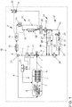
- Fig. 1 shows a motor vehicle 15 with a cooling circuit 2.
- the motor vehicle 15 has several components 5, 17, 16, 18, 19, 20, 21, 22, 25 for driving the motor vehicle 15.
- the first electrical component 5 is, for. B. a heat exchanger for a charger of a power storage device 16.
- the motor vehicle 15 further comprises a heat exchanger for an inductive circuit board (second component 17), a heat exchanger for power electronics (third component 18), a heat exchanger for an electrical machine (fourth component 19) , a DC-DC converter (fifth component 25), a cooler (sixth component 26), an HV heater (seventh component 27) and a cooler (eighth component 32).
- the cooling circuit 2 comprises a plurality of partial cooling circuits 10, 11, 28, 29, 30, 31 and a control device 7 for operating the cooling circuit 2.
- the (first) component 5, the second component 17, the third component 18 and the fourth component 19 are arranged in the cooling circuit 2.
- a first valve 14 is arranged downstream of the fourth component, via which a volume flow 1 can be conducted into the first partial cooling circuit 10 and / or into the second partial cooling circuit 11.
- the first partial cooling circuit 10 and the second partial cooling circuit 11 are arranged in a parallel circuit 13 to one another.
- a cooler is arranged as the eighth component 32, which can be bypassed via the second partial cooling circuit 11, which is designed as a bypass.
- a converter is arranged as a fifth component 25 downstream of a convergence of these partial cooling circuits 10, 11.
- the cooling circuit 2 has an expansion tank 22 for supplying the cooling circuit 2 with the coolant 4.
- a second valve 23 is arranged downstream of the converter, via which a third partial cooling circuit 28 (as a bypass to bypass the power accumulator 16) and / or at least one sixth partial cooling circuit 31 can be supplied with the volume flow 1.
- the third partial cooling circuit 28 leads the volume flow 1 back to the first pump 3.
- the sixth partial cooling circuit 31 has a second pump 20 and the power storage device 16. Sensors 21, which are provided for monitoring a temperature 9 and for determining any cooling power that may be required, are arranged upstream and downstream of the power store 16. Via the second pump 20, for. B. another volume flow 1, by actuating a third valve 24 also independently of the volume flow 1 delivered by the first pump 3, through the sixth partial cooling circuit 31 and then either through the fifth partial cooling circuit 29 or the fourth partial cooling circuit 29.
- the sixth partial cooling circuit 31 is arranged in a series circuit 12 at least with the fifth partial cooling circuit 30.
- step a) of the method the first pump 3 is operated and the coolant 4 is conveyed with a volume flow 1 through the cooling circuit 2.
- step b) a differential pressure 6 of the coolant 4 applied to the (first) component 5 is measured (see FIG Arrows proceeding from the cooling circuit 2 directly upstream and downstream of the first component, via the sensor 21 to the control unit 7).
- step c) a volume flow 1 correlating to the measured differential pressure 6 is determined using a characteristic map 8 stored in the control unit 7.
- step d) the first pump 3 is regulated by the control unit 7 using the volume flow determined via the measured differential pressure 6 1 (see arrows starting from control unit 7 towards first pump 3).
- the volume flow 1 delivered by the first pump 3 can be determined via the measured differential pressure 6 by querying the characteristics map 8. Knowing the currently funded Volume flow 1 can then be controlled by the first pump 3.
- the first pump 3 can thus also be regulated with regard to requirements from components (here, for example, the power storage device 16, which is monitored by sensors 21). If a certain cooling capacity is requested by a component or recognized as necessary on the basis of the sensors 21, the first pump 3 can generate and provide this cooling capacity with the required accuracy knowing the volume flow 1 currently being pumped, i.e. possibly in response to a different volume flow 1 can be set.
- step b) a current temperature 9 of the coolant 4 is additionally determined and taken into account in steps c) and d) (see arrows starting from the sensor 21 to the control unit 7 and from the control unit 7 to the first pump 3).
- step c) only one map 8 is taken into account, the map 8 being three-dimensional and having the differential pressure 6 as the first dimension, the temperature 9 as the second dimension and the volume flow 1 correlating to the differential pressure 6 and the temperature 9 as the third dimension.
- the volume flow 1 currently delivered by the first pump 3 can be determined from the characteristic map 8 and the first pump 3 can be regulated accordingly.
Landscapes
- Engineering & Computer Science (AREA)
- Chemical & Material Sciences (AREA)
- Mechanical Engineering (AREA)
- Manufacturing & Machinery (AREA)
- General Chemical & Material Sciences (AREA)
- Electrochemistry (AREA)
- Chemical Kinetics & Catalysis (AREA)
- General Engineering & Computer Science (AREA)
- Transportation (AREA)
- Combustion & Propulsion (AREA)
- Power Engineering (AREA)
- Sustainable Energy (AREA)
- Sustainable Development (AREA)
- Life Sciences & Earth Sciences (AREA)
- Physics & Mathematics (AREA)
- Thermal Sciences (AREA)
- Automation & Control Theory (AREA)
- Electric Propulsion And Braking For Vehicles (AREA)
Abstract
a) Betreiben der ersten Pumpe (3) und Fördern des Kühlmittels (4) durch den Kühlkreislauf (2);
b) Messen eines an der Komponente (5) anliegenden Differenzdrucks (6) des Kühlmittels (4);
c) Ermitteln eines zu dem gemessenen Differenzdruck (6) korrelierenden Volumenstroms (1) anhand eines in einem Steuergerät (7) hinterlegten Kennfelds (8) und
d) Regelung der ersten Pumpe (3) durch das Steuergerät (7) anhand des über den gemessenen Differenzdruck (6) ermittelten Volumenstroms (1).
Description
- Die Erfindung betrifft ein Verfahren zur Regelung eines Volumenstroms in einem Kühlkreislauf, insbesondere in einem Kühlkreislauf eines Stromspeichers, der bevorzugt in einem Kraftfahrzeug zum Speichern von elektrischer Energie eingesetzt wird. Insbesondere weist das Kraftfahrzeug eine elektrische Maschine zum Antrieb des Kraftfahrzeuges auf, wobei die elektrische Maschine durch die in dem Stromspeicher gespeicherte elektrische Energie antreibbar ist.
- Die Regelung eines Volumenstroms erfolgt regelmäßig über eine Pumpe, die anhand von Kennfeldern gesteuert wird. Dabei ist für jeden Kühlkreislauf und insbesondere für jede abweichende Ausführung des Kühlkreislaufs ein eigenes Kennfeld bereitzustellen. Auch geringste Änderungen des Kühlkreislaufs müssen durch Anpassungen des Kennfelds berücksichtigt werden.
- Gerade bei Kühlkreisläufen von modernen Kraftfahrzeugen muss der Volumenstrom in engen Grenzen eingestellt werden. Dabei darf weder ein bestimmter minimaler Volumenstrom unterschritten noch ein maximaler Volumenstrom überschritten werden.
- Aus der
US 6,457,442 B1 ist ein flüssigkeitsgekühlter Motor bekannt, der mehrere zueinander parallelgeschaltete Kühlkreisläufe aufweist, die von einer gemeinsamen Pumpe mit Kühlmittel versorgt werden. Die Differenzdrücke der Kühlkreisläufe werden aufeinander abgestimmt ausgeführt, so dass jeder Kühlkreislauf denselben Differenzdruck aufweist und damit mit demselben Massenstrom an Kühlmittel beaufschlagt wird. Der durch die Pumpe geförderte Massenstrom ist konstant und auf die Kühlkreisläufe abgestimmt. - Aus der
US 9,148,983 B2 - Aus der
DE 42 00 316 A1 ist ein Kältemittelhandhabungssystem bekannt, wobei ein Kältemitteldurchsatz zwischen einem Verdampfer und einem Kompressor durch ein stromaufwärts des Verdampfers angeordnetes Ventil reguliert wird, so dass eine Überhitzung des Kältemittels in dem Verdampfer verhindert wird. - Aufgabe der vorliegenden Erfindung ist es, die mit Bezug auf den Stand der Technik angeführten Probleme zumindest teilweise zu lösen. Insbesondere soll ein Verfahren vorgeschlagen werden, durch das eine genaue Regelung eines Volumenstroms durch einen Kühlkreislauf ermöglicht wird, wobei eine einfache Anpassung an einen anders ausgeführten Kühlkreislauf möglich sein soll, also gerade kein eigenes Kennfeld für jeden Kühlkreislauf bzw. jede Änderung des Kühlkreislaufs zu erstellen ist.
- Zur Lösung dieser Aufgaben trägt ein Verfahren mit den Merkmalen gemäß Patentanspruch 1 bei. Vorteilhafte Weiterbildungen sind Gegenstand der abhängigen Patentansprüche. Die in den Patentansprüchen einzeln aufgeführten Merkmale sind in technologisch sinnvoller Weise miteinander kombinierbar und können durch erläuternde Sachverhalte aus der Beschreibung und/oder Details aus der Figur ergänzt werden, wobei weitere Ausführungsvarianten der Erfindung aufgezeigt werden.
- Es wird ein Verfahren zur Regelung eines Volumenstroms in einem Kühlkreislauf vorgeschlagen, wobei der Kühlkreislauf zumindest eine erste Pumpe zur Förderung eines Kühlmittels und mindestens eine von dem Kühlmittel (z. B. ein Gas oder eine Flüssigkeit; bevorzugt aufweisend Wasser oder Öl) beaufschlagte (also z. B. durchströmte) Komponente aufweist. Das Verfahren weist zumindest die folgenden Schritte auf:
- a) Betreiben der ersten Pumpe und Fördern des Kühlmittels durch den Kühlkreislauf;
- b) Messen eines an der Komponente anliegenden Differenzdrucks des Kühlmittels;
- c) Ermitteln eines zu dem gemessenen Differenzdruck korrelierenden Volumenstroms anhand eines in einem Steuergerät hinterlegten Kennfelds und
- d) Regelung der ersten Pumpe durch das Steuergerät anhand des über den gemessenen Differenzdruck ermittelten Volumenstroms.
- Die obige (nicht abschließende) Einteilung der Verfahrensschritte in a) bis d) soll vorrangig nur zur Unterscheidung dienen und keine Reihenfolge und/oder Abhängigkeit erzwingen. Auch die Häufigkeit der Verfahrensschritte z. B. während der Einrichtung und/oder des Betriebes des Systems kann variieren. Ebenso ist möglich, dass Verfahrensschritte einander zumindest teilweise zeitlich überlagern. Insbesondere finden die Verfahrensschritte b) bis d) während Schritt a) statt. Insbesondere werden die Schritte a) bis d) in der angeführten Reihenfolge durchgeführt.
- Insbesondere wird durch das Verfahren der Zusammenhang ausgenutzt, dass sich ein Volumenstrom proportional zu einem Differenzdruck innerhalb des Kühlkreislaufs verändert. Der Differenzdruck wird insbesondere an einem sich hinsichtlich seiner geometrischen Maße nicht verändernden Abschnitt des Kühlkreislaufs ermittelt. Bevorzugt ist in dem Abschnitt die mindestens eine Komponente, ggf. mehrere Komponenten, angeordnet.
- Die Komponente ist z. B. ein Wärmetauscher, der insbesondere zur Temperierung einer Komponente (z. B. eine Leistungselektronik, ein Stromspeicher, eine elektrische Maschine, ein Wandler, ggf. aber auch eine Abgasbehandlungseinrichtung, ein Betriebsmittel, z. B. Öl oder Wasser; etc.) eines Kraftfahrzeuges eingesetzt ist.
- Über den gemessenen Differenzdruck kann insbesondere der durch die erste Pumpe geförderte Volumenstrom unter Abfrage des Kennfelds bestimmt werden. In Kenntnis des aktuell geförderten Volumenstroms kann dann die erste Pumpe geregelt werden.
- Insbesondere kann so die erste Pumpe im Hinblick auf Anforderungen von Komponenten geregelt werden. Wird z. B. eine bestimmte Kühlleistung durch eine Komponente angefordert, kann die erste Pumpe diese Kühlleistung in Kenntnis des aktuell geförderten Volumenstroms in der geforderten Genauigkeit erzeugen und bereitstellen, also ggf. auf einen anderen Volumenstrom hin eingestellt werden.
- Der Differenzdruck kann z. B. durch die Messung eines ersten Drucks (unmittelbar) stromaufwärts der Komponente und eines zweiten Drucks (unmittelbar) stromabwärts der Komponente ermittelt werden. Die Differenz zwischen dem ersten Druck und dem (kleineren) zweiten Druck bildet die Druckdifferenz.
- Insbesondere wird dabei in Schritt b) zusätzlich eine aktuelle Temperatur des Kühlmittels bestimmt und in den Schritten c) und d) berücksichtigt. Die Ermittlung der Temperatur kann zeitgleich zur Ermittlung der Druckdifferenz erfolgen. Ggf. kann aber auch ein zeitlich versetzt ermittelter Wert für die Temperatur verwendet werden (falls die Temperatur z. B. nur zyklisch ermittelt wird).
- Insbesondere wird damit der Zusammenhang berücksichtigt, dass sich der Volumenstrom zusätzlich zum Differenzdruck auch proportional zur Temperatur verändert.
- Insbesondere wird in Schritt c) nur das eine Kennfeld berücksichtigt, wobei das Kennfeld (nur) dreidimensional ist und als erste Dimension den Differenzdruck, als zweite Dimension die Temperatur und als dritte Dimension den zu dem Differenzdruck und der Temperatur korrelierenden Volumenstrom aufweist.
- Insbesondere kann also aus dem Kennfeld für eine aktuell vorliegende Temperatur und einen aktuell vorliegenden Differenzdruck der aktuell durch die erste Pumpe geförderte Volumenstrom ermittelt und die erste Pumpe entsprechend geregelt werden.
- Insbesondere wird der durch die erste Pumpe geförderte Volumenstrom in Abhängigkeit von einer angeforderten Kühlleistung der mindestens einen Komponente (ggf. von einer oder mehreren anderen oder von jeder der in dem Kühlkreislauf angeordneten Komponenten) verändert.
- Die angeforderte Kühlleistung kann z. B. durch eine Ermittlung oder Abschätzung bzw. Modellierung der Temperatur bzw. eines Temperaturverlaufs der jeweiligen Komponente bestimmt werden.
- Insbesondere weist der Kühlkreislauf mindestens einen ersten Teilkühlkreislauf und einen zweiten Teilkühlkreislauf auf, die einzeln oder gemeinsam von dem Kühlmittel durchströmt und in einer Reihenschaltung (das Kühlmittel durchströmt also z. B. zunächst den ersten Teilkühlkreislauf und erst danach den zweiten Teilkühlkreislauf) oder in einer Parallelschaltung (das Kühlmittel durchströmt nur den ersten oder den zweiten Teilkühlkreislauf, ggf. - durch Aufteilung eines Volumenstroms - beide gleichzeitig) zueinander angeordnet sind. Die Regelung der ersten Pumpe erfolgt anhand des einen Kennfelds.
- Das Kühlmittel wird insbesondere durch den Kühlkreislauf im Kreis gefördert. Dabei kann das Kühlmittel durch den ersten Teilkühlkreislauf und/oder durch den zweiten Teilkühlkreislauf strömen. Ein Teilkühlkreislauf kann z. B. einen Bypass umfassen, durch den ein Kühlmittel nur bedarfsweise gefördert wird. Weiter kann ein Teilkühlkreislauf einer bestimmten Funktion zugeordnet sein, z. B. um ein schnelles Aufheizen oder Abkühlen nur einer bestimmten Komponente oder eine geringe Wärmeableitung an Komponenten, die gerade keine Kühlung oder Erwärmung erfordern, zu realisieren.
- Es wird weiter ein Kühlkreislauf vorgeschlagen, zumindest aufweisend eine erste Pumpe zur Förderung eines Kühlmittels und mindestens eine von dem Kühlmittel durchströmte Komponente sowie ein Steuergerät zur Regelung der ersten Pumpe. Das Steuergerät ist zur Durchführung des beschriebenen Verfahrens geeignet ausgeführt.
- Insbesondere weist der Kühlkreislauf mindestens einen ersten Teilkühlkreislauf und einen zweiten Teilkühlkreislauf auf, die einzeln oder gemeinsam von dem Kühlmittel durchströmt und in einer Reihenschaltung oder in einer Parallelschaltung zueinander angeordnet sind.
- Insbesondere ist die Beaufschlagung der Teilkühlkreisläufe mit dem Kühlmittel über mindestens ein Ventil regelbar. Insbesondere ist jedem Teilkühlkreislauf zumindest ein Ventil (ggf. auch zwei Teilkühlkreisläufen auch ein gemeinsames Ventil) zugeordnet, so dass über das Ventil der Teilkühlkreislauf in den Kühlkreislauf einbindbar oder ausschließbar (bzw. mit einem Volumenstrom des Kühlmittels beaufschlagbar oder eben nicht beaufschlagbar) ist. Insbesondere kann ein Volumenstrom durch einen Teilkühlkreislauf durch ein regelbares Ventil geregelt werden, in dem das Ventil auch teilweise geöffnet bzw. geschlossen wird.
- Insbesondere ist der Kühlkreislauf einem elektrisch betriebenen Antriebsstrang eines Kraftfahrzeugs zugeordnet bzw. mit einem Antriebsstrang eines Kraftfahrzeuges zur Temperierung von Komponenten des Antriebsstrangs verbunden.
- Es wird weiter ein Kraftfahrzeug vorgeschlagen, zumindest aufweisend zumindest eine elektrische Komponente zum Antrieb des Kraftfahrzeuges, einen Stromspeicher, mindestens einen Kühlkreislauf zum Temperieren der elektrischen Komponente und des Stromspeichers und ein Steuergerät zumindest zum Betreiben des mindestens einen Kühlkreislaufs. Das Steuergerät ist zur Durchführung des beschriebenen Verfahrens geeignet ausgeführt.
- Die Ausführungen zu dem Verfahren und dem Kühlkreislauf gelten gleichermaßen für das Kraftfahrzeug und umgekehrt.
- Über die unterschiedliche Verschaltung der Teilkühlkreisläufe eines Kühlkreislaufs können insbesondere unterschiedliche Funktionen realisiert werden. So können einzelne Komponenten z. B. in einem geschlossen ausgeführten Teilkühlkreislauf (mit eigener - zweiter - Pumpe) erwärmt werden. Dafür kann z. B. nach Einstellen bzw. Beenden eines (Fahr-)Betriebs des Kraftfahrzeuges weiter vorliegende Abwärme der mindestens einen (elektrischen) Komponente (und ggf. weiterer Komponenten des Kraftfahrzeuges) in dem Teilkühlkreislauf gespeichert werden und zum Erwärmen einer ausgewählten Komponente verwendet werden. Insbesondere kann so z. B. ein in dem Kühlkreislauf, bzw. in dem Teilkühlkreislauf, angeordneter Stromspeicher mit der Restwärme temperiert werden. Damit kann die Wärmeenergie des Kraftfahrzeuges genutzt und z. B. in den Stromspeicher übertragen werden. Die so in dem Stromspeicher gespeicherte Wärme kann insbesondere für Neustarts des Kraftfahrzeuges wieder genutzt werden, wobei der Bedarf hinsichtlich einer Vorheizung des Stromspeichers reduziert werden kann.
- Weiter können bestimmte Komponenten nach Start der ersten Pumpe gezielt mit Kühlmittel beaufschlagt und gekühlt werden, während andere Komponenten erst zu einem späteren Zeitpunkt mit einer Kühlleistung bzw. dem Volumenstrom des Kühlmittels beaufschlagt werden.
- Die mindestens eine (elektrische) Komponente umfasst z. B. eine Leistungselektronik, eine elektrische Maschine, einen Stromspeicher (einen Akkumulator) oder einen Wandler, z. B. einen Gleichstromwandler.
- Insbesondere werden unterschiedliche (elektrische) Komponenten durch voneinander unterschiedliche Teilkühlkreisläufe temperiert.
- Der Kühlkreislauf kann eine zweite Pumpe aufweisen. Insbesondere ist diese zweite Pumpe in einem zuschaltbaren Teilkühlkreislauf angeordnet. Insbesondere kann zumindest zeitweise ein Kühlmittel ausschließlich durch die zweite Pumpe gefördert werden. Insbesondere kann dazu der Teilkühlkreislauf mit der zweiten Pumpe fluidtechnisch von der ersten Pumpe getrennt werden, so dass das Kühlmittel nur durch den Teilkühlkreislauf und dabei nur durch die zweite Pumpe gefördert wird. Es ist auch möglich, beide Pumpen zur Förderung des Kühlmittels gleichzeitig zu betreiben.
- Auch die zweite Pumpe kann wie die erste Pumpe anhand eines über eine Druckdifferenz und ggf. zusätzlich über eine Temperatur ermittelten Volumenstroms geregelt werden.
- Das beschriebene Verfahren zur Regelung eines Volumenstroms kann auch von einem Computer bzw. mit einem Prozessor des Steuergeräts ausgeführt werden.
- Es wird demnach auch ein System zur Datenverarbeitung vorgeschlagen, das einen Prozessor umfasst, der so angepasst/konfiguriert ist, dass er das Verfahren bzw. einen Teil der Schritte des vorgeschlagenen Verfahrens ausführt.
- Es kann ein computerlesbares Speichermedium vorgesehen sein, das Befehle umfasst, die bei der Ausführung durch einen Computer/Prozessor diesen veranlassen, das Verfahren bzw. mindestens einen Teil der Schritte des vorgeschlagenen Verfahrens auszuführen.
- Die Ausführungen zu dem Verfahren sind insbesondere auf den Kühlkreislauf, das Kraftfahrzeug, das System, das Speichermedium oder das computerimplementierte Verfahren übertragbar und umgekehrt.
- Vorsorglich sei angemerkt, dass die hier verwendeten Zahlwörter ("erste", "zweite", ...) vorrangig (nur) zur Unterscheidung von mehreren gleichartigen Gegenständen, Größen oder Prozessen dienen, also insbesondere keine Abhängigkeit und/oder Reihenfolge dieser Gegenstände, Größen oder Prozesse zueinander zwingend vorgeben. Sollte eine Abhängigkeit und/oder Reihenfolge erforderlich sein, ist dies hier explizit angegeben oder es ergibt sich offensichtlich für den Fachmann beim Studium der konkret beschriebenen Ausgestaltung.
- Die Erfindung sowie das technische Umfeld werden nachfolgend anhand der beiliegenden Figur näher erläutert. Es ist darauf hinzuweisen, dass die Erfindung durch die angeführten Ausführungsbeispiele nicht beschränkt werden soll. Insbesondere ist es, soweit nicht explizit anders dargestellt, auch möglich, Teilaspekte der in der Figur erläuterten Sachverhalte zu extrahieren und mit anderen Bestandteilen und Erkenntnissen aus der vorliegenden Beschreibung zu kombinieren. Insbesondere ist darauf hinzuweisen, dass die Figur und insbesondere die dargestellten Größenverhältnisse nur schematisch sind.
Fig. 1 zeigt ein Kraftfahrzeug 15 mit einem Kühlkreislauf 2. - Das Kraftfahrzeug 15 weist mehrere Komponenten 5, 17, 16, 18, 19, 20, 21, 22, 25 zum Antrieb des Kraftfahrzeuges 15 auf. Die erste elektrische Komponente 5 ist z. B. ein Wärmetauscher für ein Ladegerät eines Stromspeichers 16. Das Kraftfahrzeug 15 umfasst weiter einen Wärmetauscher für eine induktive Leiterplatte (zweite Komponente 17), einen Wärmetauscher für eine Leistungselektronik (dritte Komponente 18), einen Wärmetauscher für eine elektrische Maschine (vierte Komponente 19), einen DC-DC-Wandler (fünfte Komponente 25), einen Kühler (sechste Komponente 26), einen HV-Heizer (siebte Komponente 27) und einen Kühler (achte Komponente 32). Der Kühlkreislauf 2 umfasst mehrere Teilkühlkreisläufe 10, 11, 28, 29, 30, 31 und ein Steuergerät 7 zum Betreiben des Kühlkreislaufs 2.
- Die (erste) Komponente 5, die zweite Komponente 17, die dritte Komponente 18 und die vierte Komponente 19 sind in dem Kühlkreislauf 2 angeordnet. Stromabwärts der vierten Komponente ist ein erstes Ventil 14 angeordnet, über das ein Volumenstrom 1 in den ersten Teilkühlkreislauf 10 und oder in den zweiten Teilkühlkreislauf 11 leitbar ist. Der erste Teilkühlkreislauf 10 und der zweite Teilkühlkreislauf 11 sind in einer Parallelschaltung 13 zueinander angeordnet. In dem ersten Teilkühlkreislauf 10 ist ein Kühler als achte Komponente 32 angeordnet, der über den als Bypass ausgeführten zweiten Teilkühlkreislauf 11 umgangen werden kann.
- Stromabwärts einer Zusammenführung dieser Teilkühlkreisläufe 10, 11 ist ein Wandler als fünfte Komponente 25 angeordnet. Der Kühlkreislauf 2 weist einen Ausgleichsbehälter 22 zur Versorgung des Kühlkreislaufs 2 mit dem Kühlmittel 4 auf.
- Stromabwärts des Wandlers ist ein zweites Ventil 23 angeordnet, über das ein dritter Teilkühlkreislauf 28 (als Bypass zur Umgehung des Stromspeichers 16) und/oder zumindest ein sechster Teilkühlkreislauf 31 mit dem Volumenstrom 1 beaufschlagbar ist.
- Der dritte Teilkühlkreislauf 28 führt den Volumenstrom 1 zurück zur ersten Pumpe 3. Der sechste Teilkühlkreislauf 31 weist eine zweite Pumpe 20 sowie den Stromspeicher 16 auf. Stromaufwärts und stromabwärts des Stromspeichers 16 sind Sensoren 21 angeordnet, die zur Überwachung einer Temperatur 9 und zur Ermittlung einer ggf. benötigten Kühlleistung vorgesehen sind. Über die zweite Pumpe 20 kann z. B. ein weiterer Volumenstrom 1, durch Betätigung eines dritten Ventils 24 auch unabhängig von dem durch die erste Pumpe 3 geförderten Volumenstrom 1, durch den sechsten Teilkühlkreislauf 31 und dann entweder durch den fünften Teilkühlkreislauf 29 oder den vierten Teilkühlkreislauf 29 gefördert werden.
- Der sechste Teilkühlkreislauf 31 ist in einer Reihenschaltung 12 zumindest zu dem fünften Teilkühlkreislauf 30 angeordnet.
- Gemäß Schritt a) des Verfahrens erfolgt ein Betreiben der ersten Pumpe 3 und Fördern des Kühlmittels 4 mit einem Volumenstrom 1 durch den Kühlkreislauf 2. Gemäß Schritt b) erfolgt ein Messen eines an der (ersten) Komponente 5 anliegenden Differenzdrucks 6 des Kühlmittels 4 (siehe Pfeile ausgehend von dem Kühlkreislauf 2 unmittelbar stromaufwärts und stromabwärts der ersten Komponente, über den Sensor 21 hin zum Steuergerät 7). Gemäß Schritt c) erfolgt ein Ermitteln eines zu dem gemessenen Differenzdruck 6 korrelierenden Volumenstroms 1 anhand eines in dem Steuergerät 7 hinterlegten Kennfelds 8. Gemäß Schritt d) erfolgt eine Regelung der ersten Pumpe 3 durch das Steuergerät 7 anhand des über den gemessenen Differenzdruck 6 ermittelten Volumenstroms 1 (siehe Pfeile ausgehend vom Steuergerät 7 hin zur ersten Pumpe 3).
- Über den gemessenen Differenzdruck 6 kann der durch die erste Pumpe 3 geförderte Volumenstrom 1 unter Abfrage des Kennfelds 8 bestimmt werden. In Kenntnis des aktuell geförderten Volumenstroms 1 kann dann die erste Pumpe 3 geregelt werden. Die erste Pumpe 3 kann so auch im Hinblick auf Anforderungen von Komponenten (hier z. B. des Stromspeichers 16, der über Sensoren 21 überwacht wird) geregelt werden. Wird also eine bestimmte Kühlleistung durch eine Komponente angefordert bzw. aufgrund der Sensoren 21 als erforderlich erkannt, kann die erste Pumpe 3 diese Kühlleistung in Kenntnis des aktuell geförderten Volumenstroms 1 in der geforderten Genauigkeit erzeugen und bereitstellen, also ggf. auf einen anderen Volumenstrom 1 hin eingestellt werden.
- In Schritt b) wird zusätzlich eine aktuelle Temperatur 9 des Kühlmittels 4 bestimmt und in den Schritten c) und d) berücksichtigt (siehe Pfeile ausgehend von dem Sensor 21 hin zum Steuergerät 7 und vom Steuergerät 7 hin zur ersten Pumpe 3).
- In Schritt c) wird nur das eine Kennfeld 8 berücksichtigt, wobei das Kennfeld 8 dreidimensional ist und als erste Dimension den Differenzdruck 6, als zweite Dimension die Temperatur 9 und als dritte Dimension den zu dem Differenzdruck 6 und der Temperatur 9 korrelierenden Volumenstrom 1 aufweist. Aus dem Kennfeld 8 kann also für eine aktuell vorliegende Temperatur 9 und einen aktuell vorliegenden Differenzdruck 6 der aktuell durch die erste Pumpe 3 geförderte Volumenstrom 1 ermittelt und die erste Pumpe 3 entsprechend geregelt werden.
-
- 1
- Volumenstrom
- 2
- Kühlkreislauf
- 3
- erste Pumpe
- 4
- Kühlmittel
- 5
- (erste) Komponente
- 6
- Differenzdruck
- 7
- Steuergerät
- 8
- Kennfeld
- 9
- Temperatur
- 10
- erster Teilkühlkreislauf
- 11
- zweiter Teilkühlkreislauf
- 12
- Reihenschaltung
- 13
- Parallelschaltung
- 14
- erstes Ventil
- 15
- Kraftfahrzeug
- 16
- Stromspeicher
- 17
- zweite Komponente
- 18
- dritte Komponente
- 19
- vierte Komponente
- 20
- zweite Pumpe
- 21
- Sensor
- 22
- Ausgleichbehälter
- 23
- zweites Ventil
- 24
- drittes Ventil
- 25
- fünfte Komponente
- 26
- sechste Komponente
- 27
- siebte Komponente
- 28
- dritter Teilkühlkreislauf
- 29
- vierter Teilkühlkreislauf
- 30
- fünfter Teilkühlkreislauf
- 31
- sechster Teilkühlkreislauf
- 32
- achte Komponente
Claims (10)
- Verfahren zur Regelung eines Volumenstroms (1) in einem Kühlkreislauf (2), wobei der Kühlkreislauf (2) zumindest eine erste Pumpe (3) zur Förderung eines Kühlmittels (4) und mindestens eine von dem Kühlmittel (4) beaufschlagte Komponente (5) aufweist, wobei das Verfahren zumindest die folgenden Schritte aufweist:a) Betreiben der ersten Pumpe (3) und Fördern des Kühlmittels (4) durch den Kühlkreislauf (2);b) Messen eines an der Komponente (5) anliegenden Differenzdrucks (6) des Kühlmittels (4);c) Ermitteln eines zu dem gemessenen Differenzdruck (6) korrelierenden Volumenstroms (1) anhand eines in einem Steuergerät (7) hinterlegten Kennfelds (8) undd) Regelung der ersten Pumpe (3) durch das Steuergerät (7) anhand des über den gemessenen Differenzdruck (6) ermittelten Volumenstroms (1).
- Verfahren nach Patentanspruch 1, wobei in Schritt b) zusätzlich eine aktuelle Temperatur (9) des Kühlmittels (4) bestimmt und in den Schritten c) und d) berücksichtigt wird.
- Verfahren nach Patentanspruch 2, wobei in Schritt c) nur das eine Kennfeld (8) berücksichtigt wird, wobei das Kennfeld (8) dreidimensional ist und als erste Dimension den Differenzdruck (6), als zweite Dimension die Temperatur (9) und als dritte Dimension den zu dem Differenzdruck (6) und der Temperatur (9) korrelierenden Volumenstrom (1) aufweist.
- Verfahren nach einem der vorhergehenden Patentansprüche, wobei der durch die erste Pumpe (3) geförderte Volumenstrom (1) in Abhängigkeit von einer angeforderten Kühlleistung der mindestens einen Komponente (5) verändert wird.
- Verfahren nach einem der vorhergehenden Patentansprüche, wobei der Kühlkreislauf (2) mindestens einen ersten Teilkühlkreislauf (10) und einen zweiten Teilkühlkreislauf (11) aufweist, die einzeln oder gemeinsam von dem Kühlmittel (4) durchströmt und in einer Reihenschaltung (12) oder in einer Parallelschaltung (13) zueinander angeordnet sind; wobei die Regelung der ersten Pumpe (3) anhand des einen Kennfelds (8) erfolgt.
- Kühlkreislauf (2), zumindest aufweisend eine erste Pumpe (3) zur Förderung eines Kühlmittels (4) und mindestens eine von dem Kühlmittel (4) durchströmte Komponente (5) sowie ein Steuergerät (7) zur Regelung der ersten Pumpe (3), wobei das Steuergerät (7) zur Durchführung des Verfahrens nach einem der vorhergehenden Patentansprüche geeignet ausgeführt ist.
- Kühlkreislauf (2) nach Patentanspruch 6, wobei der Kühlkreislauf (2) mindestens einen ersten Teilkühlkreislauf (10) und einen zweiten Teilkühlkreislauf (11) aufweist, die einzeln oder gemeinsam von dem Kühlmittel (4) durchströmt und in einer Reihenschaltung (12) oder in einer Parallelschaltung (13) zueinander angeordnet sind.
- Kühlkreislauf (2) nach einem der vorhergehenden Patentansprüche 6 und 7, wobei die Beaufschlagung der Teilkühlkreisläufe (12, 13) mit dem Kühlmittel über mindestens ein Ventil (14) regelbar ist.
- Kühlkreislauf (2) nach einem der vorhergehenden Patentansprüche 6 bis 8, wobei der Kühlkreislauf (2) einem elektrisch betriebenen Antriebsstrang (14) eines Kraftfahrzeugs (15) zugeordnet ist.
- Kraftfahrzeug (15), zumindest aufweisend zumindest eine elektrische Komponente (5) zum Antrieb des Kraftfahrzeuges (15), einen Stromspeicher (16), mindestens einen Kühlkreislauf (2) zum Temperieren der elektrischen Komponente (5) und des Stromspeichers (16) und ein Steuergerät (7) zumindest zum Betreiben des mindestens einen Kühlkreislaufs (2); wobei das Steuergerät (7) zur Durchführung des Verfahrens nach einem der vorhergehenden Patentansprüche 1 bis 5 geeignet ausgeführt ist.
Applications Claiming Priority (1)
| Application Number | Priority Date | Filing Date | Title |
|---|---|---|---|
| DE102019210030.9A DE102019210030A1 (de) | 2019-07-08 | 2019-07-08 | Verfahren zur Regelung eines Volumenstroms |
Publications (2)
| Publication Number | Publication Date |
|---|---|
| EP3763556A1 true EP3763556A1 (de) | 2021-01-13 |
| EP3763556B1 EP3763556B1 (de) | 2023-04-19 |
Family
ID=71092449
Family Applications (1)
| Application Number | Title | Priority Date | Filing Date |
|---|---|---|---|
| EP20179557.2A Active EP3763556B1 (de) | 2019-07-08 | 2020-06-11 | Verfahren zur regelung eines volumenstroms |
Country Status (3)
| Country | Link |
|---|---|
| EP (1) | EP3763556B1 (de) |
| CN (1) | CN112197470A (de) |
| DE (1) | DE102019210030A1 (de) |
Cited By (3)
| Publication number | Priority date | Publication date | Assignee | Title |
|---|---|---|---|---|
| FR3124118A1 (fr) * | 2021-06-21 | 2022-12-23 | Psa Automobiles Sa | Systeme de gestion thermique d’elements d’un vehicule |
| CN116691427A (zh) * | 2022-02-25 | 2023-09-05 | 华晨宝马汽车有限公司 | 用于对车辆电池进行管理的方法、装置、系统、存储介质和程序产品 |
| DE102022121618A1 (de) * | 2022-08-26 | 2024-02-29 | Dr. Ing. H.C. F. Porsche Aktiengesellschaft | Thermokreislauf für ein Thermomanagementsystem eines elektrifizierten Fahrzeugs |
Families Citing this family (3)
| Publication number | Priority date | Publication date | Assignee | Title |
|---|---|---|---|---|
| DE102021126559A1 (de) | 2021-10-13 | 2023-04-13 | Volkswagen Aktiengesellschaft | Vorrichtung zur Messung einer Druckdifferenz |
| DE102022210957A1 (de) * | 2022-10-17 | 2024-04-18 | Vitesco Technologies GmbH | Temperiereinrichtung für ein Kraftfahrzeug |
| DE102024203037A1 (de) * | 2024-04-03 | 2025-10-09 | Volkswagen Aktiengesellschaft | System und Verfahren zur Temperierung einer elektrischen Traktionsbatterie |
Citations (6)
| Publication number | Priority date | Publication date | Assignee | Title |
|---|---|---|---|---|
| DE4200316A1 (de) | 1991-01-15 | 1992-07-16 | Spx Corp | Kaeltemittelhandhabungssystem mit fluessigem kaeltemittel, auch von unterschiedlichen arten |
| US5946926A (en) * | 1998-04-07 | 1999-09-07 | Hartman; Thomas B. | Variable flow chilled fluid cooling system |
| US6457442B1 (en) | 1999-11-17 | 2002-10-01 | Deutz Akiengesellschaft | Liquid-cooled internal combustion engine |
| US20110297364A1 (en) * | 2010-06-05 | 2011-12-08 | Gerhard Loeffler | Method of automatic hydraulic equalization in a fluid-flow system |
| US9148983B2 (en) | 2012-11-08 | 2015-09-29 | International Business Machines Corporation | Separate control of coolant flow through coolant circuits |
| EP3379132A1 (de) * | 2017-03-24 | 2018-09-26 | Toyota Jidosha Kabushiki Kaisha | Kühlvorrichtung für einen verbrennungsmotor |
Family Cites Families (4)
| Publication number | Priority date | Publication date | Assignee | Title |
|---|---|---|---|---|
| US5353646A (en) * | 1994-01-10 | 1994-10-11 | Atlantic Richfield Company | Multiphase fluid flow measurement |
| US20070028632A1 (en) * | 2005-08-03 | 2007-02-08 | Mingsheng Liu | Chiller control system and method |
| DE102016112093B4 (de) * | 2016-07-01 | 2020-08-27 | Dspace Digital Signal Processing And Control Engineering Gmbh | Verfahren zur Regelung eines Volumenstroms und Prüfstand zur Simulation eines Flüssigkeitskreislaufs |
| DE102017120615A1 (de) * | 2017-09-07 | 2019-03-07 | Volkswagen Aktiengesellschaft | Kraftfahrzeug mit einem Kühlsystem |
-
2019
- 2019-07-08 DE DE102019210030.9A patent/DE102019210030A1/de active Pending
-
2020
- 2020-06-11 EP EP20179557.2A patent/EP3763556B1/de active Active
- 2020-07-07 CN CN202010644776.2A patent/CN112197470A/zh active Pending
Patent Citations (6)
| Publication number | Priority date | Publication date | Assignee | Title |
|---|---|---|---|---|
| DE4200316A1 (de) | 1991-01-15 | 1992-07-16 | Spx Corp | Kaeltemittelhandhabungssystem mit fluessigem kaeltemittel, auch von unterschiedlichen arten |
| US5946926A (en) * | 1998-04-07 | 1999-09-07 | Hartman; Thomas B. | Variable flow chilled fluid cooling system |
| US6457442B1 (en) | 1999-11-17 | 2002-10-01 | Deutz Akiengesellschaft | Liquid-cooled internal combustion engine |
| US20110297364A1 (en) * | 2010-06-05 | 2011-12-08 | Gerhard Loeffler | Method of automatic hydraulic equalization in a fluid-flow system |
| US9148983B2 (en) | 2012-11-08 | 2015-09-29 | International Business Machines Corporation | Separate control of coolant flow through coolant circuits |
| EP3379132A1 (de) * | 2017-03-24 | 2018-09-26 | Toyota Jidosha Kabushiki Kaisha | Kühlvorrichtung für einen verbrennungsmotor |
Cited By (4)
| Publication number | Priority date | Publication date | Assignee | Title |
|---|---|---|---|---|
| FR3124118A1 (fr) * | 2021-06-21 | 2022-12-23 | Psa Automobiles Sa | Systeme de gestion thermique d’elements d’un vehicule |
| WO2022269144A1 (fr) * | 2021-06-21 | 2022-12-29 | Psa Automobiles Sa | Systeme de gestion thermique d'elements d'un vehicule |
| CN116691427A (zh) * | 2022-02-25 | 2023-09-05 | 华晨宝马汽车有限公司 | 用于对车辆电池进行管理的方法、装置、系统、存储介质和程序产品 |
| DE102022121618A1 (de) * | 2022-08-26 | 2024-02-29 | Dr. Ing. H.C. F. Porsche Aktiengesellschaft | Thermokreislauf für ein Thermomanagementsystem eines elektrifizierten Fahrzeugs |
Also Published As
| Publication number | Publication date |
|---|---|
| CN112197470A (zh) | 2021-01-08 |
| DE102019210030A1 (de) | 2021-01-14 |
| EP3763556B1 (de) | 2023-04-19 |
Similar Documents
| Publication | Publication Date | Title |
|---|---|---|
| EP3763556A1 (de) | Verfahren zur regelung eines volumenstroms | |
| EP2964480B1 (de) | Verfahren zum überlast-betrieb eines halbleiterschalters eines elektrifizierten kraftfahrzeugs und mittel zu dessen implementierung | |
| DE102014100215B4 (de) | Verfahren zum Steuern einer Wärmepumpe mit thermischem Speicher | |
| EP1904764B1 (de) | Verfahren zur beeinflussung der temperatur eines elektromechanischen bauteils und vorrichtung zur durchführung des verfahrens | |
| DE102013006155B4 (de) | Verfahren zum Heizen eines Fahrzeuginnenraums eines eine Brennkraftmaschine aufweisenden Fahrzeugs | |
| DE102012224453A1 (de) | Verfahren und System zum Steuern des Ladens eines Hybridfahrzeugs | |
| DE102018127409A1 (de) | Strategie/verfahren zur regelung eines gleichungsbasierten kühlsystems | |
| DE102018127788A1 (de) | Gleichungsbasiertes Zustandsschätzglied für Kühlsystemsteuergerät | |
| DE102018127497A1 (de) | dT/dt-BASIERTE KÜHLSYSTEMREGELUNG | |
| DE102020125775A1 (de) | Wärmepumpensystem und verfahren zum betreiben dieses systems | |
| DE102019210029A1 (de) | Kühlkreislauf | |
| DE102021104238A1 (de) | Verfahren zur Ansteuerung einer Hydraulikvorrichtung | |
| EP3105078B1 (de) | Verfahren zur kühlung einer komponente eines kraftfahrzeugs, kühleinrichtung und kraftfahrzeug | |
| DE102020125625A1 (de) | Wärmepumpensystem und verfahren zum betreiben des systems | |
| DE102023130530A1 (de) | Wärmemanagementsystem und steuerungsverfahren für ein wär-memanagementsystem | |
| DE102012208009A1 (de) | Verfahren zum Kühlen eines Range-Extender-Verbrennungsmotors und eine Vorrichtung zum Kühlen eines Range-Extender-Verbrennungsmotors | |
| DE112016005190T5 (de) | Elektrischer Kompressor | |
| WO2013004224A1 (de) | Fahrzeugtemperierungsvorrichtung | |
| DE102019110797A1 (de) | Verfahren zur Ansteuerung eines Elektromotors mit einer parameterangepassten Ansteuerung | |
| DE102016002518A1 (de) | Verfahren zum Betreiben eines Kraftfahrzeugs | |
| DE102021209569A1 (de) | Elektronische Steuereinheit, Hydrauliksystem und Verfahren zur Steuerung eines Hydrauliksvstems | |
| EP2011706A2 (de) | Verfahren zur Regelung eines Retarders eines Kraftfahrzeugs | |
| DE102022116936A1 (de) | Bedarfsgerechte Kühlung eines BEV | |
| DE102018218065A1 (de) | Abwärmenutzungseinrichtung, insbesondere für eine Brennkraftmaschine eines Kraftfahrzeugs | |
| DE102008002152A1 (de) | Verfahren zum Betreiben einer Antriebseinheit und Antriebseinheit |
Legal Events
| Date | Code | Title | Description |
|---|---|---|---|
| PUAI | Public reference made under article 153(3) epc to a published international application that has entered the european phase |
Free format text: ORIGINAL CODE: 0009012 |
|
| STAA | Information on the status of an ep patent application or granted ep patent |
Free format text: STATUS: THE APPLICATION HAS BEEN PUBLISHED |
|
| AK | Designated contracting states |
Kind code of ref document: A1 Designated state(s): AL AT BE BG CH CY CZ DE DK EE ES FI FR GB GR HR HU IE IS IT LI LT LU LV MC MK MT NL NO PL PT RO RS SE SI SK SM TR |
|
| AX | Request for extension of the european patent |
Extension state: BA ME |
|
| STAA | Information on the status of an ep patent application or granted ep patent |
Free format text: STATUS: REQUEST FOR EXAMINATION WAS MADE |
|
| 17P | Request for examination filed |
Effective date: 20210713 |
|
| RBV | Designated contracting states (corrected) |
Designated state(s): AL AT BE BG CH CY CZ DE DK EE ES FI FR GB GR HR HU IE IS IT LI LT LU LV MC MK MT NL NO PL PT RO RS SE SI SK SM TR |
|
| GRAP | Despatch of communication of intention to grant a patent |
Free format text: ORIGINAL CODE: EPIDOSNIGR1 |
|
| STAA | Information on the status of an ep patent application or granted ep patent |
Free format text: STATUS: GRANT OF PATENT IS INTENDED |
|
| INTG | Intention to grant announced |
Effective date: 20230127 |
|
| GRAS | Grant fee paid |
Free format text: ORIGINAL CODE: EPIDOSNIGR3 |
|
| GRAA | (expected) grant |
Free format text: ORIGINAL CODE: 0009210 |
|
| STAA | Information on the status of an ep patent application or granted ep patent |
Free format text: STATUS: THE PATENT HAS BEEN GRANTED |
|
| AK | Designated contracting states |
Kind code of ref document: B1 Designated state(s): AL AT BE BG CH CY CZ DE DK EE ES FI FR GB GR HR HU IE IS IT LI LT LU LV MC MK MT NL NO PL PT RO RS SE SI SK SM TR |
|
| REG | Reference to a national code |
Ref country code: GB Ref legal event code: FG4D Free format text: NOT ENGLISH |
|
| REG | Reference to a national code |
Ref country code: CH Ref legal event code: EP |
|
| REG | Reference to a national code |
Ref country code: DE Ref legal event code: R096 Ref document number: 502020003010 Country of ref document: DE |
|
| REG | Reference to a national code |
Ref country code: IE Ref legal event code: FG4D Free format text: LANGUAGE OF EP DOCUMENT: GERMAN |
|
| REG | Reference to a national code |
Ref country code: AT Ref legal event code: REF Ref document number: 1560946 Country of ref document: AT Kind code of ref document: T Effective date: 20230515 |
|
| P01 | Opt-out of the competence of the unified patent court (upc) registered |
Effective date: 20230524 |
|
| REG | Reference to a national code |
Ref country code: LT Ref legal event code: MG9D |
|
| REG | Reference to a national code |
Ref country code: NL Ref legal event code: MP Effective date: 20230419 |
|
| PG25 | Lapsed in a contracting state [announced via postgrant information from national office to epo] |
Ref country code: NL Free format text: LAPSE BECAUSE OF FAILURE TO SUBMIT A TRANSLATION OF THE DESCRIPTION OR TO PAY THE FEE WITHIN THE PRESCRIBED TIME-LIMIT Effective date: 20230419 |
|
| PG25 | Lapsed in a contracting state [announced via postgrant information from national office to epo] |
Ref country code: SE Free format text: LAPSE BECAUSE OF FAILURE TO SUBMIT A TRANSLATION OF THE DESCRIPTION OR TO PAY THE FEE WITHIN THE PRESCRIBED TIME-LIMIT Effective date: 20230419 Ref country code: PT Free format text: LAPSE BECAUSE OF FAILURE TO SUBMIT A TRANSLATION OF THE DESCRIPTION OR TO PAY THE FEE WITHIN THE PRESCRIBED TIME-LIMIT Effective date: 20230821 Ref country code: NO Free format text: LAPSE BECAUSE OF FAILURE TO SUBMIT A TRANSLATION OF THE DESCRIPTION OR TO PAY THE FEE WITHIN THE PRESCRIBED TIME-LIMIT Effective date: 20230719 Ref country code: ES Free format text: LAPSE BECAUSE OF FAILURE TO SUBMIT A TRANSLATION OF THE DESCRIPTION OR TO PAY THE FEE WITHIN THE PRESCRIBED TIME-LIMIT Effective date: 20230419 |
|
| PG25 | Lapsed in a contracting state [announced via postgrant information from national office to epo] |
Ref country code: RS Free format text: LAPSE BECAUSE OF FAILURE TO SUBMIT A TRANSLATION OF THE DESCRIPTION OR TO PAY THE FEE WITHIN THE PRESCRIBED TIME-LIMIT Effective date: 20230419 Ref country code: PL Free format text: LAPSE BECAUSE OF FAILURE TO SUBMIT A TRANSLATION OF THE DESCRIPTION OR TO PAY THE FEE WITHIN THE PRESCRIBED TIME-LIMIT Effective date: 20230419 Ref country code: LV Free format text: LAPSE BECAUSE OF FAILURE TO SUBMIT A TRANSLATION OF THE DESCRIPTION OR TO PAY THE FEE WITHIN THE PRESCRIBED TIME-LIMIT Effective date: 20230419 Ref country code: LT Free format text: LAPSE BECAUSE OF FAILURE TO SUBMIT A TRANSLATION OF THE DESCRIPTION OR TO PAY THE FEE WITHIN THE PRESCRIBED TIME-LIMIT Effective date: 20230419 Ref country code: IS Free format text: LAPSE BECAUSE OF FAILURE TO SUBMIT A TRANSLATION OF THE DESCRIPTION OR TO PAY THE FEE WITHIN THE PRESCRIBED TIME-LIMIT Effective date: 20230819 Ref country code: HR Free format text: LAPSE BECAUSE OF FAILURE TO SUBMIT A TRANSLATION OF THE DESCRIPTION OR TO PAY THE FEE WITHIN THE PRESCRIBED TIME-LIMIT Effective date: 20230419 Ref country code: GR Free format text: LAPSE BECAUSE OF FAILURE TO SUBMIT A TRANSLATION OF THE DESCRIPTION OR TO PAY THE FEE WITHIN THE PRESCRIBED TIME-LIMIT Effective date: 20230720 Ref country code: AL Free format text: LAPSE BECAUSE OF FAILURE TO SUBMIT A TRANSLATION OF THE DESCRIPTION OR TO PAY THE FEE WITHIN THE PRESCRIBED TIME-LIMIT Effective date: 20230419 |
|
| PG25 | Lapsed in a contracting state [announced via postgrant information from national office to epo] |
Ref country code: FI Free format text: LAPSE BECAUSE OF FAILURE TO SUBMIT A TRANSLATION OF THE DESCRIPTION OR TO PAY THE FEE WITHIN THE PRESCRIBED TIME-LIMIT Effective date: 20230419 |
|
| PG25 | Lapsed in a contracting state [announced via postgrant information from national office to epo] |
Ref country code: SK Free format text: LAPSE BECAUSE OF FAILURE TO SUBMIT A TRANSLATION OF THE DESCRIPTION OR TO PAY THE FEE WITHIN THE PRESCRIBED TIME-LIMIT Effective date: 20230419 |
|
| PG25 | Lapsed in a contracting state [announced via postgrant information from national office to epo] |
Ref country code: MC Free format text: LAPSE BECAUSE OF FAILURE TO SUBMIT A TRANSLATION OF THE DESCRIPTION OR TO PAY THE FEE WITHIN THE PRESCRIBED TIME-LIMIT Effective date: 20230419 |
|
| REG | Reference to a national code |
Ref country code: DE Ref legal event code: R097 Ref document number: 502020003010 Country of ref document: DE |
|
| PG25 | Lapsed in a contracting state [announced via postgrant information from national office to epo] |
Ref country code: SM Free format text: LAPSE BECAUSE OF FAILURE TO SUBMIT A TRANSLATION OF THE DESCRIPTION OR TO PAY THE FEE WITHIN THE PRESCRIBED TIME-LIMIT Effective date: 20230419 Ref country code: SK Free format text: LAPSE BECAUSE OF FAILURE TO SUBMIT A TRANSLATION OF THE DESCRIPTION OR TO PAY THE FEE WITHIN THE PRESCRIBED TIME-LIMIT Effective date: 20230419 Ref country code: RO Free format text: LAPSE BECAUSE OF FAILURE TO SUBMIT A TRANSLATION OF THE DESCRIPTION OR TO PAY THE FEE WITHIN THE PRESCRIBED TIME-LIMIT Effective date: 20230419 Ref country code: MC Free format text: LAPSE BECAUSE OF FAILURE TO SUBMIT A TRANSLATION OF THE DESCRIPTION OR TO PAY THE FEE WITHIN THE PRESCRIBED TIME-LIMIT Effective date: 20230419 Ref country code: EE Free format text: LAPSE BECAUSE OF FAILURE TO SUBMIT A TRANSLATION OF THE DESCRIPTION OR TO PAY THE FEE WITHIN THE PRESCRIBED TIME-LIMIT Effective date: 20230419 Ref country code: DK Free format text: LAPSE BECAUSE OF FAILURE TO SUBMIT A TRANSLATION OF THE DESCRIPTION OR TO PAY THE FEE WITHIN THE PRESCRIBED TIME-LIMIT Effective date: 20230419 Ref country code: CZ Free format text: LAPSE BECAUSE OF FAILURE TO SUBMIT A TRANSLATION OF THE DESCRIPTION OR TO PAY THE FEE WITHIN THE PRESCRIBED TIME-LIMIT Effective date: 20230419 |
|
| REG | Reference to a national code |
Ref country code: CH Ref legal event code: PL |
|
| PLBE | No opposition filed within time limit |
Free format text: ORIGINAL CODE: 0009261 |
|
| STAA | Information on the status of an ep patent application or granted ep patent |
Free format text: STATUS: NO OPPOSITION FILED WITHIN TIME LIMIT |
|
| REG | Reference to a national code |
Ref country code: BE Ref legal event code: MM Effective date: 20230630 |
|
| PG25 | Lapsed in a contracting state [announced via postgrant information from national office to epo] |
Ref country code: LU Free format text: LAPSE BECAUSE OF NON-PAYMENT OF DUE FEES Effective date: 20230611 |
|
| 26N | No opposition filed |
Effective date: 20240122 |
|
| REG | Reference to a national code |
Ref country code: IE Ref legal event code: MM4A |
|
| PG25 | Lapsed in a contracting state [announced via postgrant information from national office to epo] |
Ref country code: LU Free format text: LAPSE BECAUSE OF NON-PAYMENT OF DUE FEES Effective date: 20230611 |
|
| PG25 | Lapsed in a contracting state [announced via postgrant information from national office to epo] |
Ref country code: IE Free format text: LAPSE BECAUSE OF NON-PAYMENT OF DUE FEES Effective date: 20230611 |
|
| PG25 | Lapsed in a contracting state [announced via postgrant information from national office to epo] |
Ref country code: IE Free format text: LAPSE BECAUSE OF NON-PAYMENT OF DUE FEES Effective date: 20230611 Ref country code: CH Free format text: LAPSE BECAUSE OF NON-PAYMENT OF DUE FEES Effective date: 20230630 |
|
| PG25 | Lapsed in a contracting state [announced via postgrant information from national office to epo] |
Ref country code: SI Free format text: LAPSE BECAUSE OF FAILURE TO SUBMIT A TRANSLATION OF THE DESCRIPTION OR TO PAY THE FEE WITHIN THE PRESCRIBED TIME-LIMIT Effective date: 20230419 |
|
| PG25 | Lapsed in a contracting state [announced via postgrant information from national office to epo] |
Ref country code: SI Free format text: LAPSE BECAUSE OF FAILURE TO SUBMIT A TRANSLATION OF THE DESCRIPTION OR TO PAY THE FEE WITHIN THE PRESCRIBED TIME-LIMIT Effective date: 20230419 Ref country code: IT Free format text: LAPSE BECAUSE OF FAILURE TO SUBMIT A TRANSLATION OF THE DESCRIPTION OR TO PAY THE FEE WITHIN THE PRESCRIBED TIME-LIMIT Effective date: 20230419 Ref country code: BE Free format text: LAPSE BECAUSE OF NON-PAYMENT OF DUE FEES Effective date: 20230630 |
|
| PG25 | Lapsed in a contracting state [announced via postgrant information from national office to epo] |
Ref country code: BG Free format text: LAPSE BECAUSE OF FAILURE TO SUBMIT A TRANSLATION OF THE DESCRIPTION OR TO PAY THE FEE WITHIN THE PRESCRIBED TIME-LIMIT Effective date: 20230419 |
|
| PG25 | Lapsed in a contracting state [announced via postgrant information from national office to epo] |
Ref country code: BG Free format text: LAPSE BECAUSE OF FAILURE TO SUBMIT A TRANSLATION OF THE DESCRIPTION OR TO PAY THE FEE WITHIN THE PRESCRIBED TIME-LIMIT Effective date: 20230419 |
|
| PGFP | Annual fee paid to national office [announced via postgrant information from national office to epo] |
Ref country code: DE Payment date: 20250630 Year of fee payment: 6 |
|
| PGFP | Annual fee paid to national office [announced via postgrant information from national office to epo] |
Ref country code: GB Payment date: 20250617 Year of fee payment: 6 |
|
| PGFP | Annual fee paid to national office [announced via postgrant information from national office to epo] |
Ref country code: FR Payment date: 20250624 Year of fee payment: 6 |
|
| PGFP | Annual fee paid to national office [announced via postgrant information from national office to epo] |
Ref country code: AT Payment date: 20250721 Year of fee payment: 5 |
|
| PG25 | Lapsed in a contracting state [announced via postgrant information from national office to epo] |
Ref country code: CY Free format text: LAPSE BECAUSE OF FAILURE TO SUBMIT A TRANSLATION OF THE DESCRIPTION OR TO PAY THE FEE WITHIN THE PRESCRIBED TIME-LIMIT; INVALID AB INITIO Effective date: 20200611 |
|
| PG25 | Lapsed in a contracting state [announced via postgrant information from national office to epo] |
Ref country code: HU Free format text: LAPSE BECAUSE OF FAILURE TO SUBMIT A TRANSLATION OF THE DESCRIPTION OR TO PAY THE FEE WITHIN THE PRESCRIBED TIME-LIMIT; INVALID AB INITIO Effective date: 20200611 |
|
| PG25 | Lapsed in a contracting state [announced via postgrant information from national office to epo] |
Ref country code: TR Free format text: LAPSE BECAUSE OF FAILURE TO SUBMIT A TRANSLATION OF THE DESCRIPTION OR TO PAY THE FEE WITHIN THE PRESCRIBED TIME-LIMIT Effective date: 20230419 |