EP3763536B1 - Ink pad container - Google Patents
Ink pad container Download PDFInfo
- Publication number
- EP3763536B1 EP3763536B1 EP19200721.9A EP19200721A EP3763536B1 EP 3763536 B1 EP3763536 B1 EP 3763536B1 EP 19200721 A EP19200721 A EP 19200721A EP 3763536 B1 EP3763536 B1 EP 3763536B1
- Authority
- EP
- European Patent Office
- Prior art keywords
- stopper
- ink pad
- pad container
- fixing seat
- stamp
- Prior art date
- Legal status (The legal status is an assumption and is not a legal conclusion. Google has not performed a legal analysis and makes no representation as to the accuracy of the status listed.)
- Active
Links
- 230000037431 insertion Effects 0.000 description 38
- 238000003780 insertion Methods 0.000 description 38
- 210000003811 finger Anatomy 0.000 description 3
- 238000011084 recovery Methods 0.000 description 2
- 210000003813 thumb Anatomy 0.000 description 1
Images


Classifications
-
- B—PERFORMING OPERATIONS; TRANSPORTING
- B41—PRINTING; LINING MACHINES; TYPEWRITERS; STAMPS
- B41K—STAMPS; STAMPING OR NUMBERING APPARATUS OR DEVICES
- B41K1/00—Portable hand-operated devices without means for supporting or locating the articles to be stamped, i.e. hand stamps; Inking devices or other accessories therefor
- B41K1/36—Details
- B41K1/38—Inking devices; Stamping surfaces
- B41K1/54—Inking pads
-
- B—PERFORMING OPERATIONS; TRANSPORTING
- B41—PRINTING; LINING MACHINES; TYPEWRITERS; STAMPS
- B41K—STAMPS; STAMPING OR NUMBERING APPARATUS OR DEVICES
- B41K1/00—Portable hand-operated devices without means for supporting or locating the articles to be stamped, i.e. hand stamps; Inking devices or other accessories therefor
- B41K1/36—Details
- B41K1/38—Inking devices; Stamping surfaces
- B41K1/40—Inking devices operated by stamping movement
- B41K1/42—Inking devices operated by stamping movement with pads or rollers movable for inking
Definitions
- the present invention relates to an ink pad container, and more particularly to an ink pad container that can be easily forced to detach from a stamp and moves steadily.
- the conventional stamp has a fixing seat, a moving seat, a recovery member, a printing member, and the ink pad container.
- the fixing seat has a space formed in the fixing seat, an inner front opening formed in a front surface of the fixing seat, and two inner side openings respectively formed in two side surfaces of the fixing seat.
- the inner front opening and the two inner side openings all communicate with the space.
- the inner front opening directly communicates with the two inner side openings.
- the moving seat is disposed on the fixing seat and has an outer front opening and two outer side openings.
- the outer front opening of the moving seat is formed in a front surface of the moving seat and communicates with the inner front opening of the fixing seat.
- the two outer side openings are respectively formed in two side surfaces of the moving seat, both directly communicate with the outer front opening, and respectively communicate with the inner side openings of the fixing seat.
- the recovery member is disposed between the fixing seat and the moving seat.
- the printing member is located in the space of the fixing seat and is controlled by the moving seat.
- the ink pad container is inserted into the space of the fixing seat.
- the ink pad container has a body and two clipping elements. The two clipping elements are respectively disposed on two side surfaces of the body adjacent to a front surface of the body, are respectively located in the two inner side openings of the fixing seat, and are respectively exposed out of the outer side openings of the moving seat.
- the two clipping elements are simultaneously clipped and forced by the user to form two-point forcing.
- the forces applied on the two clipping elements are difficult to keep equal.
- the ink pad container may be rotated and stuck in the fixing seat. Therefore, the replacement of the ink pad container is inconvenient and unstable.
- the two clipping elements of the ink pad container are disposed on the two side surfaces of the body.
- the fixing seat has the two inner side openings and the moving seat has the two outer side openings in accordance with the two clipping elements. Therefore, the ink pad container cannot be applied to the moving seat without the two outer side openings and the fixing seat without the two inner side openings, so the applicability of the ink pad container is not good.
- other conventional ink pad containers are disclosed in EP 2 505 372 A1 , WO 2012/159728 A2 , EP 3 241 685 A1 , and WO 2016/197171 A2
- the present invention provides an ink pad container to mitigate or obviate the aforementioned problems.
- the objective of the invention is to provide an ink pad container that can solve the shortcoming that the forces applied on the two clipping elements of the conventional ink pad container are difficult to keep equal, the replacement of the conventional ink pad container is inconvenient and unstable, and the applicability of the conventional ink pad container is not good.
- the ink pad container is detachably disposed on a fixing seat of a stamp and has a body.
- the body has a chamber formed in the body, a bottom surface, two opposite side surfaces, a front surface, an opening formed in the bottom surface of the body and communicating with the chamber, two positioning portions formed in the two opposite side surfaces of the body respectively, a front recess formed in the front surface of the body, a front stopper formed across the front recess of the body, and a front guiding groove formed between the front stopper and the front recess.
- the body has a rear surface, a rear recess formed in the rear surface of the body, a rear stopper formed across the rear recess of the body opposite to the front stopper, and a rear guiding groove formed between the rear stopper and the rear recess.
- the ink pad container is applied to a first embodiment of the stamp.
- the fixing seat of the stamp has a front insertion opening.
- the front insertion opening is formed in a front surface of the fixing seat and is exposed out of the stamp.
- the ink pad container is inserted into the fixing seat via the front insertion opening of the fixing seat.
- the front stopper of the body is exposed out of the front insertion opening of the fixing seat.
- a nail of a user is inserted into the front guiding groove and abuts an inner edge of the front stopper for forcing to pull out the body.
- the ink pad container is applied to a third embodiment of the stamp.
- the fixing seat of the stamp has the front insertion opening formed in a front surface of the fixing seat and a rear insertion opening formed in a rear surface of the fixing seat.
- the front insertion opening and the rear insertion opening are both exposed out of the stamp.
- the rear insertion opening is covered by a moving seat of the stamp.
- the user can push the outer surface of the rear stopper of the body by a pushing device disposed on the moving seat, so that the body can be protruded out of the front insertion opening slightly, and then the nail of the user can be inserted into the front guiding groove and abut the inner edge of the front stopper for forcing to pull out the body.
- the nail of the user can be inserted into the front guiding groove and abut the inner edge of the front stopper for forcing to pull out the body without forcing on the outer surface of the rear stopper.
- the body 10B, 10C, 10D, 10E, 10F has a rear surface, a rear recess 15, a rear stopper 16, and a rear guiding groove 17.
- the rear recess 15 is formed in the rear surface of the body 10B, 10C, 10D, 10E, 10F.
- the rear stopper 16 is formed across the rear recess 15 of the body 10B, 10C, 10D, 10E, 10F opposite to the front stopper 13.
- the rear guiding groove 17 is formed between the rear stopper 16 and the rear recess 15.
- the rear stopper 16 is located at a middle of the rear surface of the body 10B, 10C, 10D, 10E, 10F, or two ends of the rear stopper 16 are respectively adjacent to the two opposite side surfaces of the body 10B, 10C, 10D, 10E, 10F.
- the rear stopper 16 is adjacent to a top surface or the bottom surface of the body 10B, 10C, 10D, 10E, 10F.
- the front stopper 13 has a first guiding surface 132 formed on an inner surface of the front stopper 13.
- the first guiding surface 132 is inclined outwardly with respect to the body 10A.
- the rear stopper 16 has a second guiding surface 162 formed on an inner surface of the rear stopper 16.
- the second guiding surface 162 is inclined outwardly with respect to the body 10A.
- the inner surface of the front stopper 13 is flat.
- the front stopper 13 has a first concave surface 133 formed on the inner surface of the front stopper 13 opposite the first convex surface 131.
- the rear stopper 16 has a second concave surface 163 formed on an inner surface of the rear stopper 16 opposite the second convex surface 161.
- the ink pad container is applied to a first embodiment of the stamp 20.
- the fixing seat 21 of the stamp 20 has a front insertion opening 211.
- the front insertion opening 211 is formed in a front surface of the fixing seat 21 and is exposed out of the stamp 20.
- the ink pad container is inserted into the fixing seat 21 via the front insertion opening 211 of the fixing seat 21 and is positioned in the fixing seat 21 by the positioning portions 11 of the body 10A.
- the front stopper 13 of the body 10A is exposed out of the front insertion opening 211 of the fixing seat 21.
- a nail 30 of a user as shown in Fig.
- the ink pad 15 is inserted into the front guiding groove 14 and abuts the first guiding surface 132 of the front stopper 13. A pulling force is forced on the first guiding surface 132 for pulling out the body 10A with single-point forcing.
- the ink pad is easy to be detached from the fixing seat 21. The replacement of the ink pad container is convenient and stable.
- the ink pad container is applied to a second embodiment of the stamp 20'.
- the fixing seat 21 of the stamp 20' has the front insertion opening 211 formed in the front surface of the fixing seat 21 and a rear insertion opening 212 formed in a rear surface of the fixing seat 21.
- the front insertion opening 211 and the rear insertion opening 212 of the fixing seat 21 are both exposed out of the stamp 20'.
- the ink pad container is inserted into the fixing seat 21 via the front insertion opening 211 of the fixing seat 21 and is positioned in the fixing seat 21 by the positioning portions 11 of the body 10B.
- the front stopper 13 of the body 10B is exposed out of the front insertion opening 211 of the fixing seat 21.
- the rear stopper 16 of the body 10B is exposed out of the rear insertion opening 212 of the fixing seat 21.
- a finger of the user can force on the second convex surface 161 of the rear stopper 16 via the rear insertion opening 212, so that the body 10B can be protruded out of the front insertion opening slightly, and then the nail 30 of the user can be inserted into the front guiding groove 14 and abuts the first guiding surface 132 of the front stopper 13.
- the pulling force is forced on the first guiding surface 132 for pulling out the body 10B with the single-point forcing.
- the ink pad is easy to be detached from the fixing seat 21. The replacement of the ink pad container is convenient and stable.
- the nail 30 of the user can be inserted into the front guiding groove 14 and abuts the first guiding surface 132 of the front stopper 13 for forcing to pull out the body 10B without firstly forcing on the second convex surface 161 of the rear stopper 16.
- the amount of the movement of the body 10B moving out of the front insertion opening 211 is increased by the single-point forcing.
- the ink pad is easy to be detached from the fixing seat 21. The replacement of the ink pad container is convenient and stable.
- the ink pad container is applied to a third embodiment of the stamp 20".
- the fixing seat 21 of the stamp 20" has the front insertion opening 211 formed in the front surface of the fixing seat 21 and a rear insertion opening 212 formed in the rear surface of the fixing seat 21.
- the front insertion opening 211 of the fixing seat 21 is exposed out of the stamp 20".
- the rear insertion opening 212 is covered by a moving seat 22 of the stamp 20".
- the stamp 20" has a pushing device 23 disposed on the moving seat 22.
- the ink pad container is inserted into the fixing seat 21 via the front insertion opening 211 of the fixing seat 21 and is positioned in the fixing seat 21 by the positioning portions 11 of the body 10B.
- the front stopper 13 of the body 10B is exposed out of the front insertion opening 211 of the fixing seat 21.
- the rear stopper 16 of the body 10B is exposed out of the rear insertion opening 212 of the fixing seat 21.
- the pushing device 23 can move with the moving seat 22 and faces the second convex surface 161 of the rear stopper 16 of the body 10B.
- the moving seat 22 can be pressed downwardly.
- the pushing device 23 driven by the moving seat 22 moves downwardly and faces the second convex surface 161 of the rear stopper 16 of the body 10B.
- the user can push the pushing device 23, and then the pushing device 23 abuts against and pushes the second convex surface 161 of the rear stopper 16 of the body 10B, so that the body 10B can move forwardly and be protruded out of the front insertion opening 211 slightly.
- the nail 30 of the user can be inserted into the front guiding groove 14 and abuts the first guiding surface 132 of the front stopper 13 for forcing to pull out the body 10B with the single-point forcing.
- the nail 30 of the user can be inserted into the front guiding groove 14 and abuts the first guiding surface 132 of the front stopper 13 for forcing to pull out the body 10B without firstly forcing on the second convex surface 161 of the rear stopper 16.
- the single front stopper 13 is formed on the front surface of the body 10A, 10B, 10C, 10D, 10E, 10F.
- the nail 30 of the user can be inserted into the front guiding groove 14 and abuts the front stopper 13.
- the body 10A, 10B, 10C, 10D, 10E, 10F can be pulled smoothly with single-point forcing.
- the single point forcing can improve the rotation caused by the different forces in the two-point forcing.
- the replacement of the ink pad container is convenient and stable by the single-point forcing.
- the choices of the replacement operations in the ink pad container are increased by the installment of the rear stopper 16.
- the ink pad container can be applied to multiple embodiments of the stamps 20, 20', 20", so the applicability of the ink pad container is good.
Description
- This application claims the priority of
Taiwan patent application No. 108208967, filed on July 9, 2019 - The present invention relates to an ink pad container, and more particularly to an ink pad container that can be easily forced to detach from a stamp and moves steadily.
- For replacing an ink pad container of a conventional stamp easily, the conventional stamp has a fixing seat, a moving seat, a recovery member, a printing member, and the ink pad container. The fixing seat has a space formed in the fixing seat, an inner front opening formed in a front surface of the fixing seat, and two inner side openings respectively formed in two side surfaces of the fixing seat. The inner front opening and the two inner side openings all communicate with the space. The inner front opening directly communicates with the two inner side openings. The moving seat is disposed on the fixing seat and has an outer front opening and two outer side openings. The outer front opening of the moving seat is formed in a front surface of the moving seat and communicates with the inner front opening of the fixing seat. The two outer side openings are respectively formed in two side surfaces of the moving seat, both directly communicate with the outer front opening, and respectively communicate with the inner side openings of the fixing seat. The recovery member is disposed between the fixing seat and the moving seat. The printing member is located in the space of the fixing seat and is controlled by the moving seat. The ink pad container is inserted into the space of the fixing seat. The ink pad container has a body and two clipping elements. The two clipping elements are respectively disposed on two side surfaces of the body adjacent to a front surface of the body, are respectively located in the two inner side openings of the fixing seat, and are respectively exposed out of the outer side openings of the moving seat.
- When replacing the ink pad container, a thumb and a second finger of a user are respectively inserted into the two outer side openings for catching the two clipping elements of the ink pad container simultaneously. The two clipping elements are pulled simultaneously. The body of the ink pad container moves out of the inner front opening of the fixing seat and the outer front opening of the moving seat for replacing the ink pad container conveniently.
- However, the two clipping elements are simultaneously clipped and forced by the user to form two-point forcing. In the two-point forcing, the forces applied on the two clipping elements are difficult to keep equal. When the forces applied on the two clipping elements are different, the ink pad container may be rotated and stuck in the fixing seat. Therefore, the replacement of the ink pad container is inconvenient and unstable.
- Moreover, the two clipping elements of the ink pad container are disposed on the two side surfaces of the body. The fixing seat has the two inner side openings and the moving seat has the two outer side openings in accordance with the two clipping elements. Therefore, the ink pad container cannot be applied to the moving seat without the two outer side openings and the fixing seat without the two inner side openings, so the applicability of the ink pad container is not good. In addition, other conventional ink pad containers are disclosed in
EP 2 505 372 A1 ,WO 2012/159728 A2 ,EP 3 241 685 A1 , andWO 2016/197171 A2 - To overcome the shortcomings, the present invention provides an ink pad container to mitigate or obviate the aforementioned problems.
- The objective of the invention is to provide an ink pad container that can solve the shortcoming that the forces applied on the two clipping elements of the conventional ink pad container are difficult to keep equal, the replacement of the conventional ink pad container is inconvenient and unstable, and the applicability of the conventional ink pad container is not good.
- The ink pad container is detachably disposed on a fixing seat of a stamp and has a body. The body has a chamber formed in the body, a bottom surface, two opposite side surfaces, a front surface, an opening formed in the bottom surface of the body and communicating with the chamber, two positioning portions formed in the two opposite side surfaces of the body respectively, a front recess formed in the front surface of the body, a front stopper formed across the front recess of the body, and a front guiding groove formed between the front stopper and the front recess.
- Furthermore, the body has a rear surface, a rear recess formed in the rear surface of the body, a rear stopper formed across the rear recess of the body opposite to the front stopper, and a rear guiding groove formed between the rear stopper and the rear recess.
- The ink pad container is applied to a first embodiment of the stamp. The fixing seat of the stamp has a front insertion opening. The front insertion opening is formed in a front surface of the fixing seat and is exposed out of the stamp. The ink pad container is inserted into the fixing seat via the front insertion opening of the fixing seat. The front stopper of the body is exposed out of the front insertion opening of the fixing seat. To replace the body, a nail of a user is inserted into the front guiding groove and abuts an inner edge of the front stopper for forcing to pull out the body.
- The ink pad container is applied to a second embodiment of the stamp. The fixing seat of the stamp has the front insertion opening formed in the front surface of the fixing seat and a rear insertion opening formed in a rear surface of the fixing seat. The front insertion opening and the rear insertion opening are both exposed out of the stamp. During replacement, a finger of the user can force on an outer surface of the rear stopper of the body via the rear insertion opening, so that the body can be protruded out of the front insertion opening slightly, and then the nail of the user can be inserted into the front guiding groove and abut the inner edge of the front stopper for forcing to pull out the body. Alternatively, the nail of the user can be inserted into the front guiding groove and abut the inner edge of the front stopper for forcing to pull out the body without firstly forcing on the outer surface of the rear stopper.
- The ink pad container is applied to a third embodiment of the stamp. The fixing seat of the stamp has the front insertion opening formed in a front surface of the fixing seat and a rear insertion opening formed in a rear surface of the fixing seat. The front insertion opening and the rear insertion opening are both exposed out of the stamp. The rear insertion opening is covered by a moving seat of the stamp. During replacement, the user can push the outer surface of the rear stopper of the body by a pushing device disposed on the moving seat, so that the body can be protruded out of the front insertion opening slightly, and then the nail of the user can be inserted into the front guiding groove and abut the inner edge of the front stopper for forcing to pull out the body. Alternatively, the nail of the user can be inserted into the front guiding groove and abut the inner edge of the front stopper for forcing to pull out the body without forcing on the outer surface of the rear stopper.
- As abovementioned, the single front stopper is formed on the front surface of the body for removing the body with a single-point forcing. In the single-point forcing, there is no need for equal force distribution as in the two-point forcing. The single-point forcing can eliminate the rotation caused by the different forces in the two-point forcing. The replacement of the ink pad container is convenient and stable. In addition, the ink pad container can be applied to multiple embodiments of the stamps, so the applicability of the ink pad container is good.
- Other objectives, advantages and novel features of the invention will become more apparent from the following detailed description when taken in conjunction with the accompanying drawings.
-
- Fig. 1
- is a perspective view of a first embodiment of an ink pad container in accordance with the present invention;
- Fig. 2
- is a perspective view of a second embodiment of an ink pad container in accordance with the present invention;
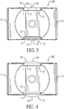
- Fig. 3
- is a top view of the ink pad container in
Fig. 2 ; - Fig. 4
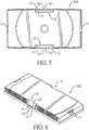
- is a top view of a third embodiment of an ink pad container in accordance with the present invention;
- Fig. 5
- is a top view of a fourth embodiment of an ink pad container in accordance with the present invention;
- Fig. 6
- is a perspective view of a fifth embodiment of an ink pad container in accordance with the present invention;
- Fig. 7
- is a top view of the ink pad container in
Fig. 6 ; - Fig. 8
- is a front view of a sixth embodiment of an ink pad container in accordance with the present invention;
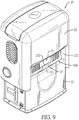
- Fig. 9
- is an operational perspective view of the ink pad container in
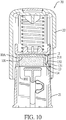
Fig. 1 showing that the ink pad container is disposed in a first embodiment of a stamp; - Fig. 10
- is a cross sectional side view of the stamp in
Fig. 9 ; - Fig. 11
- is an operational perspective view of the ink pad container in
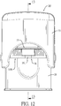
Fig. 2 showing that the ink pad container is disposed in a second embodiment of the stamp; - Fig. 12
- is a rear view of the stamp in
Fig. 11 ; - Fig. 13
- is a cross sectional side view of the stamp along line 13-13 in
Fig. 12 ; - Fig. 14
- is an operational cross sectional side view of the stamp in
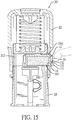
Fig. 13 showing that a body of the ink pad container is pushed; - Fig. 15
- is an operational cross sectional side view of the stamp in
Fig. 14 showing that a body of the ink pad container is pulled; - Fig. 16
- is another operational cross sectional side view of the stamp in
Fig. 13 showing that a body of the ink pad container is pulled; - Fig. 17
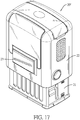
- is an operational perspective view of the ink pad container in
Fig. 2 showing that the ink pad container is disposed in a third embodiment of the stamp; - Fig. 18
- is another operational perspective view of the ink pad container in
Fig. 2 showing that the ink pad container is disposed in a third embodiment of a stamp; - Fig. 19
- is a cross sectional side view of the stamp in
Fig. 17 ; - Fig. 20
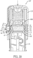
- is an operational cross sectional side view of the stamp in
Fig. 17 showing that a body of the ink pad container is pushed by a pushing device of the stamp; and - Fig. 21
- is an operational cross sectional side view of the stamp in
Fig. 17 showing that a body of the ink pad container is pulled. - With reference to
Figs. 9 ,11 ,17 , and18 , an ink pad container in accordance with the present invention is detachably disposed on a fixingseat 21 of astamp Figs. 1 to 8 , and10 , the ink pad container has abody body chamber 101, anopening 102, two positioningportions 11, afront recess 12, afront stopper 13, and a front guidinggroove 14. Thechamber 101 is formed in thebody opening 102 is formed in the bottom surface of thebody chamber 101. The twopositioning portions 11 are formed in the two opposite side surfaces of thebody front recess 12 is formed in the front surface of thebody front stopper 13 is formed across thefront recess 12 of thebody front guiding groove 14 is formed between thefront stopper 13 and thefront recess 12. - Furthermore, the
front stopper 13 is located at a middle of the front surface of thebody front stopper 13 are respectively adjacent to the two opposite side surfaces of thebody Figs. 1 and8 , thefront stopper 13 is adjacent to a top surface or the bottom surface of thebody - The
body rear recess 15, arear stopper 16, and arear guiding groove 17. Therear recess 15 is formed in the rear surface of thebody rear stopper 16 is formed across therear recess 15 of thebody front stopper 13. Therear guiding groove 17 is formed between therear stopper 16 and therear recess 15. - Furthermore, the
rear stopper 16 is located at a middle of the rear surface of thebody rear stopper 16 are respectively adjacent to the two opposite side surfaces of thebody rear stopper 16 is adjacent to a top surface or the bottom surface of thebody - With reference to
Figs. 3, 4 ,5 , and7 , thefront stopper 13 has a firstconvex surface 131 formed on an outer surface of thefront stopper 13, and therear stopper 16 has a secondconvex surface 161 formed on an outer surface of therear stopper 16. With reference toFigs. 3 and5 , the firstconvex surface 131 is located at a middle of the outer surface of thefront stopper 13, and the secondconvex surface 161 is located at a middle of the outer surface of therear stopper 16. With reference toFigs. 4 and7 , two ends of the firstconvex surface 131 are respectively adjacent to the two ends of thefront stopper 13. Two ends of the secondconvex surface 161 are respectively adjacent to the two ends of therear stopper 16. - With reference to
Figs. 3 and5 , thefront stopper 13 has afirst guiding surface 132 formed on an inner surface of thefront stopper 13. Thefirst guiding surface 132 is inclined outwardly with respect to thebody 10A. Therear stopper 16 has asecond guiding surface 162 formed on an inner surface of therear stopper 16. Thesecond guiding surface 162 is inclined outwardly with respect to thebody 10A. The inner surface of thefront stopper 13 is flat. With reference toFig. 7 , thefront stopper 13 has a firstconcave surface 133 formed on the inner surface of thefront stopper 13 opposite the firstconvex surface 131. Therear stopper 16 has a second concave surface 163 formed on an inner surface of therear stopper 16 opposite the secondconvex surface 161. - With reference to
Figs. 9 and10 , the ink pad container is applied to a first embodiment of thestamp 20. The fixingseat 21 of thestamp 20 has afront insertion opening 211. Thefront insertion opening 211 is formed in a front surface of the fixingseat 21 and is exposed out of thestamp 20. The ink pad container is inserted into the fixingseat 21 via thefront insertion opening 211 of the fixingseat 21 and is positioned in the fixingseat 21 by thepositioning portions 11 of thebody 10A. Thefront stopper 13 of thebody 10A is exposed out of thefront insertion opening 211 of the fixingseat 21. To replace the ink pad container, anail 30 of a user as shown inFig. 15 is inserted into thefront guiding groove 14 and abuts thefirst guiding surface 132 of thefront stopper 13. A pulling force is forced on thefirst guiding surface 132 for pulling out thebody 10A with single-point forcing. The ink pad is easy to be detached from the fixingseat 21. The replacement of the ink pad container is convenient and stable. - With reference to
Figs. 11 to 13 , the ink pad container is applied to a second embodiment of the stamp 20'. The fixingseat 21 of the stamp 20' has thefront insertion opening 211 formed in the front surface of the fixingseat 21 and arear insertion opening 212 formed in a rear surface of the fixingseat 21. Thefront insertion opening 211 and the rear insertion opening 212 of the fixingseat 21 are both exposed out of the stamp 20'. The ink pad container is inserted into the fixingseat 21 via thefront insertion opening 211 of the fixingseat 21 and is positioned in the fixingseat 21 by thepositioning portions 11 of thebody 10B. Thefront stopper 13 of thebody 10B is exposed out of thefront insertion opening 211 of the fixingseat 21. Therear stopper 16 of thebody 10B is exposed out of the rear insertion opening 212 of the fixingseat 21. - With reference to
Figs. 14 and15 , during replacement, a finger of the user can force on the secondconvex surface 161 of therear stopper 16 via therear insertion opening 212, so that thebody 10B can be protruded out of the front insertion opening slightly, and then thenail 30 of the user can be inserted into thefront guiding groove 14 and abuts thefirst guiding surface 132 of thefront stopper 13. The pulling force is forced on thefirst guiding surface 132 for pulling out thebody 10B with the single-point forcing. The ink pad is easy to be detached from the fixingseat 21. The replacement of the ink pad container is convenient and stable. - Alternatively, with reference to
Fig. 16 , thenail 30 of the user can be inserted into thefront guiding groove 14 and abuts thefirst guiding surface 132 of thefront stopper 13 for forcing to pull out thebody 10B without firstly forcing on the secondconvex surface 161 of therear stopper 16. The amount of the movement of thebody 10B moving out of thefront insertion opening 211 is increased by the single-point forcing. The ink pad is easy to be detached from the fixingseat 21. The replacement of the ink pad container is convenient and stable. - With reference to
Figs. 17 to 19 , the ink pad container is applied to a third embodiment of thestamp 20". The fixingseat 21 of thestamp 20" has thefront insertion opening 211 formed in the front surface of the fixingseat 21 and arear insertion opening 212 formed in the rear surface of the fixingseat 21. Thefront insertion opening 211 of the fixingseat 21 is exposed out of thestamp 20". Therear insertion opening 212 is covered by a movingseat 22 of thestamp 20". Thestamp 20" has a pushingdevice 23 disposed on the movingseat 22. The ink pad container is inserted into the fixingseat 21 via thefront insertion opening 211 of the fixingseat 21 and is positioned in the fixingseat 21 by thepositioning portions 11 of thebody 10B. Thefront stopper 13 of thebody 10B is exposed out of thefront insertion opening 211 of the fixingseat 21. Therear stopper 16 of thebody 10B is exposed out of the rear insertion opening 212 of the fixingseat 21. The pushingdevice 23 can move with the movingseat 22 and faces the secondconvex surface 161 of therear stopper 16 of thebody 10B. - With reference to
Figs. 20 and21 , during replacement, firstly, the movingseat 22 can be pressed downwardly. The pushingdevice 23 driven by the movingseat 22 moves downwardly and faces the secondconvex surface 161 of therear stopper 16 of thebody 10B. The user can push the pushingdevice 23, and then the pushingdevice 23 abuts against and pushes the secondconvex surface 161 of therear stopper 16 of thebody 10B, so that thebody 10B can move forwardly and be protruded out of thefront insertion opening 211 slightly. Thenail 30 of the user can be inserted into thefront guiding groove 14 and abuts thefirst guiding surface 132 of thefront stopper 13 for forcing to pull out thebody 10B with the single-point forcing. - Alternatively, the
nail 30 of the user can be inserted into thefront guiding groove 14 and abuts thefirst guiding surface 132 of thefront stopper 13 for forcing to pull out thebody 10B without firstly forcing on the secondconvex surface 161 of therear stopper 16. - Accordingly, the
single front stopper 13 is formed on the front surface of thebody nail 30 of the user can be inserted into thefront guiding groove 14 and abuts thefront stopper 13. Thebody rear stopper 16. In addition, the ink pad container can be applied to multiple embodiments of thestamps
Claims (12)
- An ink pad container comprising:a body (10A, 10B, 10C, 10D, 10E, 10F) havinga chamber (101) formed in the body (10A, 10B, 10C, 10D, 10E, 10F);a bottom surface;two opposite side surfaces;a front surface;an opening (102) formed in the bottom surface of the body (10A, 10B, 10C, 10D, 10E, 10F) and communicating with the chamber (101);two positioning portions (11) formed in the two opposite side surfaces of the body (10A, 10B, 10C, 10D, 10E, 10F) respectively; anda front recess (12) formed in the front surface of the body (10A, 10B, 10C, 10D, 10E, 10F);characterized in that the ink pad container further comprises:a front stopper (13) formed across the front recess (12) of the body (10A, 10B, 10C, 10D, 10E, 10F); anda front guiding groove (14) formed between the front stopper (13) and the front recess (12).
- The ink pad container as claimed in claim 1, wherein the front stopper (13) is located at a middle of the front surface of the body (10A, 10B, 10C, 10D, 10E, 10F).
- The ink pad container as claimed in claim 1 or 2, wherein the front stopper (13) is adjacent to one of a top surface and the bottom surface of the body (10A, 10B, 10C, 10D, 10E, 10F).
- The ink pad container as claimed in claim 1, wherein the body (10A, 10B, 10C, 10D, 10E, 10F) hasa rear surface;a rear recess (15) formed in the rear surface of the body (10A, 10B, 10C, 10D, 10E, 10F);a rear stopper (16) formed across the rear recess (15) of the body (10A, 10B, 10C, 10D, 10E, 10F) opposite to the front stopper (13); anda rear guiding groove (17) formed between the rear stopper (16) and the rear recess (15).
- The ink pad container as claimed in claim 4, wherein the front stopper (13) is located at a middle of the front surface of the body (10A, 10B, 10C, 10D, 10E, 10F), and the rear stopper (16) is located at a middle of the rear surface of the body (10A, 10B, 10C, 10D, 10E, 10F).
- The ink pad container as claimed in claim 4 or 5, wherein the front stopper (13) and the rear stopper (16) both are adjacent to one of a top surface and the bottom surface of the body (10A, 10B, 10C, 10D, 10E, 10F).
- The ink pad container as claimed in claim 4 or 5, wherein the front stopper (13) has a first convex surface (131) formed on an outer surface of the front stopper (13), and the rear stopper (16) has a second convex surface (161) formed on an outer surface of the rear stopper (16).
- The ink pad container as claimed in claim 7, wherein the first convex surface (131) is located at a middle of the outer surface of the front stopper (13), and the second convex surface (161) is located at a middle of the outer surface of the rear stopper (16).
- The ink pad container as claimed in claim 7, wherein two ends of the first convex surface (131) are respectively adjacent to two ends of the front stopper (13), and two ends of the second convex surface (161) are respectively adjacent to two ends of the rear stopper (16).
- The ink pad container as claimed in claim 4 or 5, wherein an inner surface of the front stopper (13) is flat.
- The ink pad container as claimed in claim 7, wherein the front stopper (13) has a first guiding surface (132) formed on an inner surface of the front stopper (13), the first guiding surface (132) is inclined outwardly with respect to the body (10A, 10B, 10D), the rear stopper (16) has a second guiding surface (162) formed on an inner surface of the rear stopper (16), and the second guiding surface (162) is inclined outwardly with respect to the body (10A, 10B, 10D).
- The ink pad container as claimed in claim 8, wherein the front stopper (13) has a first concave surface (133) formed on an inner surface of the front stopper (13), and the rear stopper (16) has a second concave surface (163) formed on an inner surface of the rear stopper (16).
Priority Applications (1)
| Application Number | Priority Date | Filing Date | Title |
|---|---|---|---|
| PL19200721T PL3763536T3 (en) | 2019-07-09 | 2019-10-01 | Ink pad container |
Applications Claiming Priority (1)
| Application Number | Priority Date | Filing Date | Title |
|---|---|---|---|
| TW108208967U TWM587599U (en) | 2019-07-09 | 2019-07-09 | Improved stamp holder |
Publications (2)
| Publication Number | Publication Date |
|---|---|
| EP3763536A1 EP3763536A1 (en) | 2021-01-13 |
| EP3763536B1 true EP3763536B1 (en) | 2021-09-08 |
Family
ID=68109170
Family Applications (1)
| Application Number | Title | Priority Date | Filing Date |
|---|---|---|---|
| EP19200721.9A Active EP3763536B1 (en) | 2019-07-09 | 2019-10-01 | Ink pad container |
Country Status (5)
| Country | Link |
|---|---|
| US (1) | US11260685B2 (en) |
| EP (1) | EP3763536B1 (en) |
| ES (1) | ES2896928T3 (en) |
| PL (1) | PL3763536T3 (en) |
| TW (1) | TWM587599U (en) |
Family Cites Families (14)
| Publication number | Priority date | Publication date | Assignee | Title |
|---|---|---|---|---|
| US454499A (en) * | 1891-06-23 | Self-inking hand-stamp | ||
| US2950676A (en) * | 1957-05-15 | 1960-08-30 | Bankers & Merchants Inc | Stamp |
| US3359897A (en) * | 1964-06-11 | 1967-12-26 | Charles R Harte | Graph marking device |
| AT6731U1 (en) * | 2003-03-18 | 2004-03-25 | Colop Stempelerzeugung Skopek | SELF-STAINING STAMP WITH HIGH-PURPLE COLORING AND COLOR CUSHION CONTAINER HIEFÜR |
| US6945172B1 (en) * | 2004-06-10 | 2005-09-20 | Shiny Shih | Housing assembly for a self-inking stamp |
| AT507833A3 (en) * | 2009-01-30 | 2013-06-15 | Trodat Gmbh | STAMP AND PUNCH CUSHION FOR A SELF-STAINED STAMP |
| AT12677U1 (en) * | 2011-03-30 | 2012-09-15 | Colop Stempelerzeugung Skopek | COLOR CUSHION HOLDER AND SELF-STAINING STAMP |
| AT511453B1 (en) * | 2011-05-24 | 2012-12-15 | Trodat Gmbh | STAMP AND ASSOCIATED STAMP PILLOW |
| TWM460781U (en) * | 2013-01-16 | 2013-09-01 | Sun Same Entpr Co Ltd | Stamp |
| AT513898B1 (en) * | 2013-01-24 | 2019-01-15 | Colop Stempelerzeugung Skopek Gmbh & Co Kg | Device for guiding a ink pad container and self-inking stamp |
| AT517322A1 (en) * | 2015-06-10 | 2016-12-15 | Trodat Gmbh | Stamp and impression unit, in particular as a spare part for a stamp |
| AT517321A1 (en) * | 2015-06-10 | 2016-12-15 | Trodat Gmbh | stamp |
| CN205523139U (en) * | 2016-03-30 | 2016-08-31 | 上海吉普生办公用品有限公司 | A photosensitive seal for overturning on seal face support |
| TWM561004U (en) * | 2018-03-02 | 2018-06-01 | Sun Same Enterprises Co Ltd | Stamp pad positioning device |
-
2019
- 2019-07-09 TW TW108208967U patent/TWM587599U/en unknown
- 2019-09-17 US US16/573,071 patent/US11260685B2/en active Active
- 2019-10-01 ES ES19200721T patent/ES2896928T3/en active Active
- 2019-10-01 EP EP19200721.9A patent/EP3763536B1/en active Active
- 2019-10-01 PL PL19200721T patent/PL3763536T3/en unknown
Also Published As
| Publication number | Publication date |
|---|---|
| ES2896928T3 (en) | 2022-02-28 |
| PL3763536T3 (en) | 2021-12-27 |
| EP3763536A1 (en) | 2021-01-13 |
| US11260685B2 (en) | 2022-03-01 |
| US20210008913A1 (en) | 2021-01-14 |
| TWM587599U (en) | 2019-12-11 |
Similar Documents
| Publication | Publication Date | Title |
|---|---|---|
| CA2485986C (en) | Stamp and device for receiving an inking pad | |
| US10421201B2 (en) | Safety cutter apparatus and system | |
| US5913629A (en) | Writing implement including an input stylus | |
| EP3042741B1 (en) | Razor with detachable replacement blade | |
| ES2534329T3 (en) | Desktop mini stapler | |
| CA2854394C (en) | Holding device for cards and/or banknotes | |
| US20040055903A1 (en) | Slide open container | |
| EP2266809B1 (en) | A self-inking stamp | |
| EP2433762A1 (en) | Cutter knife | |
| US7527635B2 (en) | Surgical knife | |
| MX2010011155A (en) | Razor handle for a retractable shaving cartridge and a razor comprising such a razor handle. | |
| EP0212644A1 (en) | A stapler | |
| EP1982843A1 (en) | Retractable writing implement | |
| US20110088270A1 (en) | Slip Resistant Ruler | |
| KR20110043522A (en) | Knock type writing instrument | |
| EP3763536B1 (en) | Ink pad container | |
| US9039316B2 (en) | Writing instrument having a protective element for the retractable tip | |
| JPWO2005034295A1 (en) | Card connector | |
| EP1281652A2 (en) | Adhesive tape adhering device | |
| US5709145A (en) | Matrix plate holder and matrix plate for a hand stamp | |
| EP2660010A2 (en) | Fastening tool assembly | |
| EP3533618B1 (en) | Positioning device for an ink pad container | |
| US20040035310A1 (en) | Self-inking Stamp | |
| US20220072894A1 (en) | Retractable Writing Instrument | |
| US5554095A (en) | Bias tape maker |
Legal Events
| Date | Code | Title | Description |
|---|---|---|---|
| PUAI | Public reference made under article 153(3) epc to a published international application that has entered the european phase |
Free format text: ORIGINAL CODE: 0009012 |
|
| STAA | Information on the status of an ep patent application or granted ep patent |
Free format text: STATUS: REQUEST FOR EXAMINATION WAS MADE |
|
| 17P | Request for examination filed |
Effective date: 20201202 |
|
| AK | Designated contracting states |
Kind code of ref document: A1 Designated state(s): AL AT BE BG CH CY CZ DE DK EE ES FI FR GB GR HR HU IE IS IT LI LT LU LV MC MK MT NL NO PL PT RO RS SE SI SK SM TR |
|
| AX | Request for extension of the european patent |
Extension state: BA ME |
|
| GRAP | Despatch of communication of intention to grant a patent |
Free format text: ORIGINAL CODE: EPIDOSNIGR1 |
|
| STAA | Information on the status of an ep patent application or granted ep patent |
Free format text: STATUS: GRANT OF PATENT IS INTENDED |
|
| INTG | Intention to grant announced |
Effective date: 20210510 |
|
| GRAS | Grant fee paid |
Free format text: ORIGINAL CODE: EPIDOSNIGR3 |
|
| GRAA | (expected) grant |
Free format text: ORIGINAL CODE: 0009210 |
|
| STAA | Information on the status of an ep patent application or granted ep patent |
Free format text: STATUS: THE PATENT HAS BEEN GRANTED |
|
| AK | Designated contracting states |
Kind code of ref document: B1 Designated state(s): AL AT BE BG CH CY CZ DE DK EE ES FI FR GB GR HR HU IE IS IT LI LT LU LV MC MK MT NL NO PL PT RO RS SE SI SK SM TR |
|
| REG | Reference to a national code |
Ref country code: GB Ref legal event code: FG4D |
|
| REG | Reference to a national code |
Ref country code: CH Ref legal event code: EP Ref country code: AT Ref legal event code: REF Ref document number: 1428260 Country of ref document: AT Kind code of ref document: T Effective date: 20210915 |
|
| REG | Reference to a national code |
Ref country code: DE Ref legal event code: R096 Ref document number: 602019007515 Country of ref document: DE |
|
| REG | Reference to a national code |
Ref country code: IE Ref legal event code: FG4D |
|
| REG | Reference to a national code |
Ref country code: GR Ref legal event code: EP Ref document number: 20210402759 Country of ref document: GR Effective date: 20211111 |
|
| REG | Reference to a national code |
Ref country code: LT Ref legal event code: MG9D |
|
| REG | Reference to a national code |
Ref country code: NL Ref legal event code: MP Effective date: 20210908 |
|
| PG25 | Lapsed in a contracting state [announced via postgrant information from national office to epo] |
Ref country code: SE Free format text: LAPSE BECAUSE OF FAILURE TO SUBMIT A TRANSLATION OF THE DESCRIPTION OR TO PAY THE FEE WITHIN THE PRESCRIBED TIME-LIMIT Effective date: 20210908 Ref country code: RS Free format text: LAPSE BECAUSE OF FAILURE TO SUBMIT A TRANSLATION OF THE DESCRIPTION OR TO PAY THE FEE WITHIN THE PRESCRIBED TIME-LIMIT Effective date: 20210908 Ref country code: FI Free format text: LAPSE BECAUSE OF FAILURE TO SUBMIT A TRANSLATION OF THE DESCRIPTION OR TO PAY THE FEE WITHIN THE PRESCRIBED TIME-LIMIT Effective date: 20210908 Ref country code: LT Free format text: LAPSE BECAUSE OF FAILURE TO SUBMIT A TRANSLATION OF THE DESCRIPTION OR TO PAY THE FEE WITHIN THE PRESCRIBED TIME-LIMIT Effective date: 20210908 Ref country code: BG Free format text: LAPSE BECAUSE OF FAILURE TO SUBMIT A TRANSLATION OF THE DESCRIPTION OR TO PAY THE FEE WITHIN THE PRESCRIBED TIME-LIMIT Effective date: 20211208 Ref country code: HR Free format text: LAPSE BECAUSE OF FAILURE TO SUBMIT A TRANSLATION OF THE DESCRIPTION OR TO PAY THE FEE WITHIN THE PRESCRIBED TIME-LIMIT Effective date: 20210908 Ref country code: NO Free format text: LAPSE BECAUSE OF FAILURE TO SUBMIT A TRANSLATION OF THE DESCRIPTION OR TO PAY THE FEE WITHIN THE PRESCRIBED TIME-LIMIT Effective date: 20211208 |
|
| PG25 | Lapsed in a contracting state [announced via postgrant information from national office to epo] |
Ref country code: LV Free format text: LAPSE BECAUSE OF FAILURE TO SUBMIT A TRANSLATION OF THE DESCRIPTION OR TO PAY THE FEE WITHIN THE PRESCRIBED TIME-LIMIT Effective date: 20210908 |
|
| REG | Reference to a national code |
Ref country code: ES Ref legal event code: FG2A Ref document number: 2896928 Country of ref document: ES Kind code of ref document: T3 Effective date: 20220228 |
|
| PG25 | Lapsed in a contracting state [announced via postgrant information from national office to epo] |
Ref country code: IS Free format text: LAPSE BECAUSE OF FAILURE TO SUBMIT A TRANSLATION OF THE DESCRIPTION OR TO PAY THE FEE WITHIN THE PRESCRIBED TIME-LIMIT Effective date: 20220108 Ref country code: SM Free format text: LAPSE BECAUSE OF FAILURE TO SUBMIT A TRANSLATION OF THE DESCRIPTION OR TO PAY THE FEE WITHIN THE PRESCRIBED TIME-LIMIT Effective date: 20210908 Ref country code: SK Free format text: LAPSE BECAUSE OF FAILURE TO SUBMIT A TRANSLATION OF THE DESCRIPTION OR TO PAY THE FEE WITHIN THE PRESCRIBED TIME-LIMIT Effective date: 20210908 Ref country code: RO Free format text: LAPSE BECAUSE OF FAILURE TO SUBMIT A TRANSLATION OF THE DESCRIPTION OR TO PAY THE FEE WITHIN THE PRESCRIBED TIME-LIMIT Effective date: 20210908 Ref country code: PT Free format text: LAPSE BECAUSE OF FAILURE TO SUBMIT A TRANSLATION OF THE DESCRIPTION OR TO PAY THE FEE WITHIN THE PRESCRIBED TIME-LIMIT Effective date: 20220110 Ref country code: NL Free format text: LAPSE BECAUSE OF FAILURE TO SUBMIT A TRANSLATION OF THE DESCRIPTION OR TO PAY THE FEE WITHIN THE PRESCRIBED TIME-LIMIT Effective date: 20210908 Ref country code: EE Free format text: LAPSE BECAUSE OF FAILURE TO SUBMIT A TRANSLATION OF THE DESCRIPTION OR TO PAY THE FEE WITHIN THE PRESCRIBED TIME-LIMIT Effective date: 20210908 Ref country code: AL Free format text: LAPSE BECAUSE OF FAILURE TO SUBMIT A TRANSLATION OF THE DESCRIPTION OR TO PAY THE FEE WITHIN THE PRESCRIBED TIME-LIMIT Effective date: 20210908 |
|
| REG | Reference to a national code |
Ref country code: DE Ref legal event code: R097 Ref document number: 602019007515 Country of ref document: DE |
|
| REG | Reference to a national code |
Ref country code: BE Ref legal event code: MM Effective date: 20211031 |
|
| PG25 | Lapsed in a contracting state [announced via postgrant information from national office to epo] |
Ref country code: MC Free format text: LAPSE BECAUSE OF FAILURE TO SUBMIT A TRANSLATION OF THE DESCRIPTION OR TO PAY THE FEE WITHIN THE PRESCRIBED TIME-LIMIT Effective date: 20210908 |
|
| PLBE | No opposition filed within time limit |
Free format text: ORIGINAL CODE: 0009261 |
|
| STAA | Information on the status of an ep patent application or granted ep patent |
Free format text: STATUS: NO OPPOSITION FILED WITHIN TIME LIMIT |
|
| PG25 | Lapsed in a contracting state [announced via postgrant information from national office to epo] |
Ref country code: LU Free format text: LAPSE BECAUSE OF NON-PAYMENT OF DUE FEES Effective date: 20211001 Ref country code: DK Free format text: LAPSE BECAUSE OF FAILURE TO SUBMIT A TRANSLATION OF THE DESCRIPTION OR TO PAY THE FEE WITHIN THE PRESCRIBED TIME-LIMIT Effective date: 20210908 Ref country code: BE Free format text: LAPSE BECAUSE OF NON-PAYMENT OF DUE FEES Effective date: 20211031 |
|
| 26N | No opposition filed |
Effective date: 20220609 |
|
| PG25 | Lapsed in a contracting state [announced via postgrant information from national office to epo] |
Ref country code: IE Free format text: LAPSE BECAUSE OF NON-PAYMENT OF DUE FEES Effective date: 20211001 |
|
| PGFP | Annual fee paid to national office [announced via postgrant information from national office to epo] |
Ref country code: PL Payment date: 20220923 Year of fee payment: 4 Ref country code: FR Payment date: 20220804 Year of fee payment: 4 |
|
| REG | Reference to a national code |
Ref country code: AT Ref legal event code: UEP Ref document number: 1428260 Country of ref document: AT Kind code of ref document: T Effective date: 20210908 |
|
| PGFP | Annual fee paid to national office [announced via postgrant information from national office to epo] |
Ref country code: ES Payment date: 20221229 Year of fee payment: 4 |
|
| PGFP | Annual fee paid to national office [announced via postgrant information from national office to epo] |
Ref country code: GR Payment date: 20221019 Year of fee payment: 4 |
|
| REG | Reference to a national code |
Ref country code: CH Ref legal event code: PL |
|
| PG25 | Lapsed in a contracting state [announced via postgrant information from national office to epo] |
Ref country code: CY Free format text: LAPSE BECAUSE OF FAILURE TO SUBMIT A TRANSLATION OF THE DESCRIPTION OR TO PAY THE FEE WITHIN THE PRESCRIBED TIME-LIMIT Effective date: 20210908 |
|
| PG25 | Lapsed in a contracting state [announced via postgrant information from national office to epo] |
Ref country code: LI Free format text: LAPSE BECAUSE OF NON-PAYMENT OF DUE FEES Effective date: 20221031 Ref country code: HU Free format text: LAPSE BECAUSE OF FAILURE TO SUBMIT A TRANSLATION OF THE DESCRIPTION OR TO PAY THE FEE WITHIN THE PRESCRIBED TIME-LIMIT; INVALID AB INITIO Effective date: 20191001 Ref country code: CH Free format text: LAPSE BECAUSE OF NON-PAYMENT OF DUE FEES Effective date: 20221031 |
|
| PG25 | Lapsed in a contracting state [announced via postgrant information from national office to epo] |
Ref country code: SI Free format text: LAPSE BECAUSE OF FAILURE TO SUBMIT A TRANSLATION OF THE DESCRIPTION OR TO PAY THE FEE WITHIN THE PRESCRIBED TIME-LIMIT Effective date: 20210908 |
|
| PGFP | Annual fee paid to national office [announced via postgrant information from national office to epo] |
Ref country code: CZ Payment date: 20230921 Year of fee payment: 5 |
|
| PGFP | Annual fee paid to national office [announced via postgrant information from national office to epo] |
Ref country code: IT Payment date: 20230925 Year of fee payment: 5 Ref country code: DE Payment date: 20230906 Year of fee payment: 5 |