EP1281652A2 - Adhesive tape adhering device - Google Patents
Adhesive tape adhering device Download PDFInfo
- Publication number
- EP1281652A2 EP1281652A2 EP02255298A EP02255298A EP1281652A2 EP 1281652 A2 EP1281652 A2 EP 1281652A2 EP 02255298 A EP02255298 A EP 02255298A EP 02255298 A EP02255298 A EP 02255298A EP 1281652 A2 EP1281652 A2 EP 1281652A2
- Authority
- EP
- European Patent Office
- Prior art keywords
- inner case
- side wall
- adhesive tape
- outer case
- tape
- Prior art date
- Legal status (The legal status is an assumption and is not a legal conclusion. Google has not performed a legal analysis and makes no representation as to the accuracy of the status listed.)
- Withdrawn
Links
Images


Classifications
-
- B—PERFORMING OPERATIONS; TRANSPORTING
- B43—WRITING OR DRAWING IMPLEMENTS; BUREAU ACCESSORIES
- B43L—ARTICLES FOR WRITING OR DRAWING UPON; WRITING OR DRAWING AIDS; ACCESSORIES FOR WRITING OR DRAWING
- B43L19/00—Erasers, rubbers, or erasing devices; Holders therefor
-
- B—PERFORMING OPERATIONS; TRANSPORTING
- B65—CONVEYING; PACKING; STORING; HANDLING THIN OR FILAMENTARY MATERIAL
- B65H—HANDLING THIN OR FILAMENTARY MATERIAL, e.g. SHEETS, WEBS, CABLES
- B65H35/00—Delivering articles from cutting or line-perforating machines; Article or web delivery apparatus incorporating cutting or line-perforating devices, e.g. adhesive tape dispensers
- B65H35/0006—Article or web delivery apparatus incorporating cutting or line-perforating devices
- B65H35/002—Hand-held or table apparatus
- B65H35/0026—Hand-held or table apparatus for delivering pressure-sensitive adhesive tape
- B65H35/0033—Hand-held or table apparatus for delivering pressure-sensitive adhesive tape and affixing it to a surface
-
- Y—GENERAL TAGGING OF NEW TECHNOLOGICAL DEVELOPMENTS; GENERAL TAGGING OF CROSS-SECTIONAL TECHNOLOGIES SPANNING OVER SEVERAL SECTIONS OF THE IPC; TECHNICAL SUBJECTS COVERED BY FORMER USPC CROSS-REFERENCE ART COLLECTIONS [XRACs] AND DIGESTS
- Y10—TECHNICAL SUBJECTS COVERED BY FORMER USPC
- Y10T—TECHNICAL SUBJECTS COVERED BY FORMER US CLASSIFICATION
- Y10T156/00—Adhesive bonding and miscellaneous chemical manufacture
- Y10T156/12—Surface bonding means and/or assembly means with cutting, punching, piercing, severing or tearing
- Y10T156/1348—Work traversing type
-
- Y—GENERAL TAGGING OF NEW TECHNOLOGICAL DEVELOPMENTS; GENERAL TAGGING OF CROSS-SECTIONAL TECHNOLOGIES SPANNING OVER SEVERAL SECTIONS OF THE IPC; TECHNICAL SUBJECTS COVERED BY FORMER USPC CROSS-REFERENCE ART COLLECTIONS [XRACs] AND DIGESTS
- Y10—TECHNICAL SUBJECTS COVERED BY FORMER USPC
- Y10T—TECHNICAL SUBJECTS COVERED BY FORMER US CLASSIFICATION
- Y10T156/00—Adhesive bonding and miscellaneous chemical manufacture
- Y10T156/17—Surface bonding means and/or assemblymeans with work feeding or handling means
- Y10T156/1788—Work traversing type and/or means applying work to wall or static structure
- Y10T156/1795—Implement carried web supply
-
- Y—GENERAL TAGGING OF NEW TECHNOLOGICAL DEVELOPMENTS; GENERAL TAGGING OF CROSS-SECTIONAL TECHNOLOGIES SPANNING OVER SEVERAL SECTIONS OF THE IPC; TECHNICAL SUBJECTS COVERED BY FORMER USPC CROSS-REFERENCE ART COLLECTIONS [XRACs] AND DIGESTS
- Y10—TECHNICAL SUBJECTS COVERED BY FORMER USPC
- Y10T—TECHNICAL SUBJECTS COVERED BY FORMER US CLASSIFICATION
- Y10T156/00—Adhesive bonding and miscellaneous chemical manufacture
- Y10T156/18—Surface bonding means and/or assembly means with handle or handgrip
Definitions
- the present invention relates to adhering means for adhesive tape, and more particularly, to an adhesive tape adhering device in which a roll of adhesive tape is mounted in a case, a bottom portion of which is pressed against an adherend to which the adhesive tape is applied and then the tape is cut.
- a horizontal bottom plate of a case is provided at its front portion with a tape exit.
- An inner case is mounted to the outer case such that a lower central portion of the inner case can longitudinally swing around a horizontal axis.
- One side of the inner case is open.
- An upper portion outer peripheral wall of the inner case is exposed by an opening of an upper portion of the outer case. Bumps and dips, a projecting piece and a fingertip engaging portion comprising a projection are provided on this portion.
- Adhesive tape which is wound into a roll-shape such that its adhering surface comes inside, is rotatably mounted on a side wall of the inner case.
- a lower portion of the inner case has an opening not bounded by a peripheral wall.
- the opening is provided at its front end with a pressing roller which supports the adhesive tape and pushes the adhesive tape against the adherend which faces the opening in the horizontal bottom plate.
- An upper end of a swinging plate interposed between the side wall of the inner case and the outer case is pivotally mounted to the outer case.
- a cutting blade for the adhesive tape is provided on an upper portion of a lateral supporting piece on a lower end of the swinging plate.
- the inner case is mounted in the outer case, which has a horizontal bottom plate, such that the inner case can swing longitudinally.
- the swinging plate which associatively rotates with the inner case is mounted between the outer case and the inner case.
- a tip end of the adhesive tape, wound into a roll-like shape in the inner case, is brought into contact with a lower portion of the pressing roller at the lower portion front end of the inner case via the upper side of a guide roller of the inner case.
- the swinging plate is provided, at its lower portion, with the tape cutting blade.
- the inner case is forwardly inclined around a lower end of the inner case, and the pressing roller on the front portion lower end of the inner case pushes the adhesive tape against the adherend. At that time, the swinging plate rotates forwardly, thereby retreating the blade on its lower end. If the outer case is pulled backward while pressing the same downward in this state, the adhesive tape is adhered to the adherend while being dispensed from the inner case.
- the adhesive tape is adhered to the adherend by the above operation, and when the adhesive tape has been adhered over a predetermined length, if the fingertip engaging portion on the upper portion of the inner case is pulled backward, the pressing roller is moved upwardly, the swinging plate is rotated backwardly, the blade on the lower end is moved below the pressing roller, and the blade cuts the adhesive tape below the pressing roller.
- the above conventional device is extremely convenient because the adhesive tape can be adhered and cut continuously.
- the outer case bottom surface comprises a horizontal surface from its front portion to its rear portion, the adhering device cannot stably move in a straight line during the adhering operation.
- the outer peripheral surface lower portion of the pressing roller coincides with the outer case bottom surface, there is an adverse possibility that a reliable adhering operation cannot be carried out if there are small bumps and dips on the adherend surface or if the pressing roller is worn, or due to lack of assembling precision of the adhering device.
- an object of the present invention to provide an adhesive tape adhering device which is improved so that the adhering device can be easily moved in a straight line, and so that a reliable adhering operation can be achieved.
- an adhesive tape adhering device in which adhesive tape is discharged from an opening in a lower or bottom surface of a casing, wherein straight lower end edges of a pair of left and right outer case side wall plates extend from the casing lower bottom surface.
- the lower end edges extend by a small distance from the casing bottom surface.
- the lower end edges extend by 0.1 to 1.0 mm from the casing bottom surface.
- an adhesive tape adhering device comprising an outer case provided at its bottom surface with a tape exit opening, a pair of left and right side wall plates, an inner case mounted such that the inner case can longitudinally swing around an inner case rotation shaft fixed to a lower portion of the outer case, the inner case having a tape mounting shaft on which a roll of adhesive tape can be mounted and an inner case side wall, a pressing roller mounted to a front lower tip end of the inner case side wall at right angles thereto, and a guide roller mounted to the inner case side wall on the adhering surface side of the adhesive tape for guiding the adhesive tape dispensed from the roll of adhesive tape to the pressing roller, wherein there is a small distance between the bottom surface of the outer case and lower end surfaces of the side wall plates (end surfaces of straight lower end edges thereof).
- a portion of the bottom surface behind the tape exit opening of the outer case lies in the same plane as that of the lower end surfaces of the side wall plates of the outer case (end surfaces of straight lower end edges thereof).
- the pressing roller passes through the tape exit opening by a forward swinging operation of the inner case, and projects from the lower end surfaces of the side wall plates (end surfaces of the straight lower end edges thereof).
- the inner case is provided at its front upper portion with a fingertip engaging portion.
- the outer case and the inner case are engaged or engageable with each other by means of a first stopper disposed on a bottom surface of the outer case and a second stopper disposed on a rear upper portion of the inner case side wall and by means of a plate-like or coil-like spring.
- the device further comprises a rod-like tape core cylinder retaining member which is fixed to a central portion of the side wall plate of the outer case at right angles thereto and which passes through an oval or elongate cam hole formed in the inner case, wherein the tape core cylinder retaining member pushes an adhesive tape core cylindrical inner surface as a result of rearward swinging movement of the inner case caused by stress of the spring.
- a rod-like tape core cylinder retaining member which is fixed to a central portion of the side wall plate of the outer case at right angles thereto and which passes through an oval or elongate cam hole formed in the inner case, wherein the tape core cylinder retaining member pushes an adhesive tape core cylindrical inner surface as a result of rearward swinging movement of the inner case caused by stress of the spring.
- the device further comprises a swinging plate between one of the side wall plates of the outer case and the inner case side wall, wherein the swinging plate is pivotally mounted to a swinging plate shaft fixed to the outer case side wall, a pin fixed to the inner case side wall engages with a cam hole formed in a rear portion of the swinging plate, a lateral supporting piece at a lower end of the swinging plate is provided with a cutting blade for cutting the adhesive tape, the swinging plate and the inner case side wall are associatively moved such that the cutting blade is retreated forwardly of the pressing roller when the inner case is forwardly inclined by the longitudinal swinging operation of the fingertip engaging portion, and the cutting blade moves below the lifted pressing roller when the inner case is rearwardly inclined.
- the outer case has one openable side and one of the side wall plates is attachable to and detachable from the openable side.
- the lower end surface of one as opposed to both side wall plates may project a small distance downwardly beyond the bottom surface of the outer case.
- the present invention provides an adhesive tape adhering device in which adhesive tape is discharged from an opening in a casing lower or bottom surface, straight lower end edges of a pair of left and right outer case side plates extend through a slight distance (e.g. 0.1 to 2.0 mm, preferably 0.3 to 0.8 mm). Therefore, an edge surface of a straight lower end edge of each of the pair of left and right side wall plates functions as a guide, and it is possible to easily move the adhesive tape adhering device in a straight line over an adherend surface without deviating laterally during the adhering operation.
- a slight distance e.g. 0.1 to 2.0 mm, preferably 0.3 to 0.8 mm
- the invention provides an adhesive tape adhering device comprising an outer case provided at its bottom surface with a tape exit opening, a pair of left and right side wall plates, an inner case mounted such that the inner case can longitudinally swing around an inner case rotation shaft fixed to a lower portion of the outer case, the inner case having a tape mounting shaft on which a roll of adhesive tape can be mounted, and an inner case side wall, a pressing roller mounted to a front lower tip end of the inner case side wall at right angles thereto, and a guide roller mounted to the inner case side wall on the adhering surface side of the adhesive tape for guiding the adhesive tape dispensed from the roll of adhesive tape to the pressing roller, wherein there is a small distance between the bottom surface of the outer case and lower end surfaces of the side wall plates.
- both of the lower end surfaces of the pair of left and right side wall plates function as the guides, and even if there are small bumps and dips on the surface of the adherend, it is possible to easily move the adhesive tape adhering device in a straight line without deviating laterally, and to adhere the tape.
- a portion of the bottom surface behind the tape exit opening of the outer case lies in the same plane as that of the lower end surfaces of the side wall plates of the outer case.
- the inner case is provided at its front upper portion with a fingertip engaging portion so that the inner case can be swung in the longitudinal direction by engagement of the fingertip engaging portion.
- a plate-like or coil-like spring is preferably provided between a first stopper disposed on the bottom surface of the outer case and a second stopper disposed on a rear upper portion of the inner case side wall, so that the inner case is automatically returned when the adhering operation has been completed.
- the adhesive tape adhering device further comprises a rod-like tape core cylinder retaining member which is fixed to a central portion of the side wall plate of the outer case at right angles thereto and which passes through an oval or elongate cam hole formed in the inner case, wherein the tape core cylinder retaining member pushes an adhesive tape core cylindrical inner surface as a result of rearward swinging movement of the inner case caused by stress of the spring. Accordingly when the device is used, the roll of adhesive tape is not rotated unintentionally.
- the adhesive tape adhering device may further comprise a swinging plate between one of the side wall plates of the outer case and the inner case side wall, wherein the swinging plate is pivotally mounted to a swinging plate shaft fixed to the outer case side wall, a pin fixed to the inner case side wall engages with a cam hole formed in a rear portion of the swinging plate, a lateral supporting piece at a lower end of the swinging plate is provided with a cutting blade for cutting the adhesive tape, the swinging plate and the inner case side wall are associatively moved such that the cutting blade is retreated forwardly of the pressing roller when the inner case is forwardly inclined by the longitudinal swinging operation of the fingertip engaging portion, and the cutting blade moves below the lifted pressing roller when the inner case is rearwardly inclined. Therefore, the adhesive tape can be cut.
- the pin may be fixed to the swinging plate and engage with a cam hole formed in the inner case side wall.
- reference number 1 represents an outer case
- reference number 2 represents a tapered bottom plate
- reference number 2a represents a bottom surface of the outer case
- reference number 3 represents tape exit opening
- reference numbers 4, 4' represent side wall plates
- reference numbers 4a, 4'a represent lower end surfaces of straight lower end edges of the pair of left and right side wall plates
- reference number 5 represents an inner case
- reference number 6 represents an inner case rotation shaft
- reference number 7 represents a slight distance 7 provided between lower end surfaces 4a, 4'a of straight lower end edges of the pair of left and right side wall plates 4, 4' and bottom surfaces 2a, 28a of the outer case
- reference number 8 represents an upper openings
- reference number 9 represents a fingertip engaging portion
- reference number 10 represents a projecting piece
- reference number 11 represents a tape core cylinder retaining member
- reference number 12 represents an inner case side wall
- reference number 13 represents a tape mounting shaft
- reference number 14 represents a stopper
- reference number 15 represents an adhesive tape
- reference number 16 represents a tape core
- the outer case 1 is provided with side wall plates 4(4'), one of which is openable or removable and a bottom surface of the case is provided with the tape exit opening 3 and an opening 8 above the tape exit opening 3.
- the inner case 5 and an inner case side wall 12, one side of which is open, are mounted such that they can longitudinally swing around a rotation shaft 6 of the inner case fixed to a rear lower portion of the outer case 1.
- the inner case 5 comprises a fingertip engaging portion 9 provided on a front upper portion of the inner case side wall 12, a projecting piece 10 provided on a tip end of the inner case side wall 12, a tape mounting shaft 13 on which the roll of adhesive tape 15 can be mounted at a substantially central portion of the inner case side wall 12, a pressing roller 17 mounted to a front bottom tip end of the inner case side wall 12 at right angles, and a guide roller 19 mounted to the inner case side wall 12 on an adhering surface of the adhesive tape 15 rearwardly of the pressing roller 17 for guiding the adhesive tape 15 dispensed from the roll of adhesive tape 15 toward the pressing roller 17.
- the inner case 5 can be swung longitudinally by pressing on the fingertip engaging portion 9.
- the inner case 5 includes a stopper 14 which can be swung by the fingertip engaging portion 9 and a further stopper 30 disposed on the bottom surface in the outer case 1.
- the inner case 5 automatically returns rearward when the adhering operation is completed.
- the inner case 5 automatically returns rearwardly. It is fixed to a central portion of the side wall plate 4(4') of the outer case 1 at right angles thereto, and the rod-like tape core cylinder retaining member 11 passes through the oval cam hole 26 of the inner case 5 and pushes against an inner surface of the adhesive tape core cylinder 16 as a result of the rearward swinging operation of the inner case 5 under the influence of the leaf spring 29.
- a swinging plate 20 between the side wall plate 4(4') of the outer case 1 and the inner case side wall 12.
- the swinging plate 20 is pivotally supported by the swinging plate shaft 21 fixed to the outer case side wall 4.
- the pin 23 is fixed to an upper portion of the inner case side wall 12 and rearwardly of the swinging plate shaft 21 and engages with the cam hole 22 disposed in the swinging plate 20.
- a cutting blade 25 for cutting the adhesive tape 15 is provided on a lower end of the swinging plate 20 and on the supporting piece 24 thereof.
- the cutting blade 25 is retreated forwardly of the pressing roller 17 when the inner case 5 is forwardly inclined by the longitudinal swinging operation of the fingertip engaging portion 9, and the swinging plate 20 and the inner case side wall 12 are associatively moved so that the cutting blade 25 moves below the pressing roller 17 when the inner case 5 is inclined rearwardly.
- Fig. 1 the roll of adhesive tape 15 is mounted on the tape mounting shaft 13, and the adhesive tape tip end a is pulled out.
- the projecting piece 10 on the tip end of the fingertip engaging portion 9 is pushed and the adhesive tape tip end a is allowed to pass around an upper portion of the guide roller 19 and then is pulled out to an outer peripheral lower portion of the pressing roller 17.
- a rear portion lower side corner of the outer case 1 is brought into contact with the adherend, and a front lower end surface of the side wall plate 4(4') of the outer case 1 is pushed against the adherend 18.
- a front portion of the tapered bottom plate 2 of the outer case 1 is situated on the same level as the lower end surfaces of the side wall plates 4(4'). Therefore, the surface of the adherend 18 is pushed immediately prior to the adhering of the tape thereto, and the adhering operation can accordingly be carried out more reliably.
- the tape core cylinder retaining member 11 pushes against an inner surface of the adhesive tape core cylinder 16 by the rearward swinging operation of the inner case 5 under the action of the stress of the leaf spring 29, and idling or movement caused by vibration of the roll of adhesive tape 15 is prevented.
- a blade tip of the cutting blade 25 fixed to the supporting piece 24 is inclined as shown in Fig. 5, which makes it possible to cut the adhesive tape 15 from its edge easily.
- the projecting piece 10 is formed with an upward bend at its front end which, together with the fingertip engaging portion 9 at a front upper portion of the inner case 5, is configured to fit the man's hand 27.
- Surfaces with which the man's hand are adapted to engage may be provided with bumps and dips so that the surface is not slippery.
- one side of the outer case 1 is openable and the side wall plate 4' can be attached and detached by engaging means (not shown).
- reference number 7 represents the small distance which is provided between the lower end surfaces 4a, 4'a of the straight lower edges of the pair of left and right side wall plates 4, 4' and the bottom surfaces 2a (28a) of the outer case. Because of this small distance 7, the lower end surfaces 4a, 4'a of the straight lower edges of the pair of left and right side wall plates 4, 4' function as rail-like guides, the adhesive tape adhering device can be easily moved in a straight line on the surface of the adherend 18 without deviating laterally, and it is accordingly possible to adhere the adhesive tape 15 thereon in a straight line.
- the lower end surfaces 4a, 4'a of the side wall plates 4, 4' are flat and stable.
- the lower end surfaces 4a, 4'a are substantially chamfered, and the lower end surfaces 4a, 4'a have reduced thickness, and the surfaces function as rail-like guides and lateral slip is even less likely to occur.
- an edge surface of the straight lower end edge of each of the pair of left and right side wall plates functions as the a guide, the adhesive tape adhering device moves easily in a straight line on the surface of the adherend without deviating laterally, and it is possible to easily adhere the adhesive tape in a straight line.
- a portion of the rear bottom surface of the tape exit opening of the outer case is situated in the same plane as that of the lower end surface of the side wall plates of the outer case. Therefore, the adherend immediately before it is pressed by the pressing roller will be held flat, and it is accordingly possible to reliably adhere the tape.
- the pressing roller passes through the tape exit opening by the forward swinging operation of the inner case, and the pressing roller projects from the lower end surface of the side wall plate. Therefore, the pressing roller can directly push on the adherend and reliably adhere the tape.
- the inner case is provided at its front upper portion with the fingertip engaging portion. Therefore, the device easily fits a man's hand and the adhering operation becomes easy.
- the outer case and the inner case are engaged or engageable with each other by means of the plate-like or coil-like spring between the stopper disposed on the bottom surface of the outer case and the stopper disposed on a rear end upper portion of the inner case side wall. Therefore, if the man's hand is relaxed when the adhering operation has been completed, the inner case is automatically inclined rearwardly, and the adhesive tape can be cut at the same time.
- the tape core cylinder retaining member pushes the adhesive tape core cylindrical surface by the rearward swinging operation of the inner case by the stress of the spring, and movement which may be caused by vibration or the like of the roll of adhesive tape can be prevented when the device is not being used.
- the cutting blade draws a substantially horizontal arc and cuts the adhesive tape by a slight swinging operation of the inner case, and excellent cutting efficiency can be obtained.
- the outer case since one side of the outer case is opened or openable, and the outer case has a detachable side wall plate, it is easy to attach and detach the roll of adhesive tape or empty core cylinder.
Abstract
Description
- The present invention relates to adhering means for adhesive tape, and more particularly, to an adhesive tape adhering device in which a roll of adhesive tape is mounted in a case, a bottom portion of which is pressed against an adherend to which the adhesive tape is applied and then the tape is cut.
- The present applicant proposed and patented an adhesive tape adhering device capable of adhering and cutting adhesive tape in Japanese Patent No. 2611132 titled "Adhesive Tape Adhering Device". The subject matter of the invention of this prior patent is as follows: A horizontal bottom plate of a case is provided at its front portion with a tape exit. An inner case is mounted to the outer case such that a lower central portion of the inner case can longitudinally swing around a horizontal axis. One side of the inner case is open. An upper portion outer peripheral wall of the inner case is exposed by an opening of an upper portion of the outer case. Bumps and dips, a projecting piece and a fingertip engaging portion comprising a projection are provided on this portion. Adhesive tape, which is wound into a roll-shape such that its adhering surface comes inside, is rotatably mounted on a side wall of the inner case. A lower portion of the inner case has an opening not bounded by a peripheral wall. The opening is provided at its front end with a pressing roller which supports the adhesive tape and pushes the adhesive tape against the adherend which faces the opening in the horizontal bottom plate. An upper end of a swinging plate interposed between the side wall of the inner case and the outer case is pivotally mounted to the outer case. A cutting blade for the adhesive tape is provided on an upper portion of a lateral supporting piece on a lower end of the swinging plate. The swinging plate and the inner case are associatively moved such that the blade is retreated forwardly of the pressing roller when the inner case is forwardly inclined, and the blade moves below the lifted pressing roller when the inner case is rearwardly inclined.
- In the prior patented invention, the inner case is mounted in the outer case, which has a horizontal bottom plate, such that the inner case can swing longitudinally. The swinging plate, which associatively rotates with the inner case is mounted between the outer case and the inner case. A tip end of the adhesive tape, wound into a roll-like shape in the inner case, is brought into contact with a lower portion of the pressing roller at the lower portion front end of the inner case via the upper side of a guide roller of the inner case. The swinging plate is provided, at its lower portion, with the tape cutting blade.
- If the fingertip engaging portion is pushed forwardly using a fingertip, the inner case is forwardly inclined around a lower end of the inner case, and the pressing roller on the front portion lower end of the inner case pushes the adhesive tape against the adherend. At that time, the swinging plate rotates forwardly, thereby retreating the blade on its lower end. If the outer case is pulled backward while pressing the same downward in this state, the adhesive tape is adhered to the adherend while being dispensed from the inner case.
- The adhesive tape is adhered to the adherend by the above operation, and when the adhesive tape has been adhered over a predetermined length, if the fingertip engaging portion on the upper portion of the inner case is pulled backward, the pressing roller is moved upwardly, the swinging plate is rotated backwardly, the blade on the lower end is moved below the pressing roller, and the blade cuts the adhesive tape below the pressing roller.
- The above conventional device is extremely convenient because the adhesive tape can be adhered and cut continuously. However, since the outer case bottom surface comprises a horizontal surface from its front portion to its rear portion, the adhering device cannot stably move in a straight line during the adhering operation. Further, since the outer peripheral surface lower portion of the pressing roller coincides with the outer case bottom surface, there is an adverse possibility that a reliable adhering operation cannot be carried out if there are small bumps and dips on the adherend surface or if the pressing roller is worn, or due to lack of assembling precision of the adhering device.
- In view of the above circumstances, it is an object of the present invention to provide an adhesive tape adhering device which is improved so that the adhering device can be easily moved in a straight line, and so that a reliable adhering operation can be achieved.
- In view of the above matters, the present inventor studied hard and as a result, the inventor solved the above problem.
- According to a first aspect of the invention there is provided an adhesive tape adhering device in which adhesive tape is discharged from an opening in a lower or bottom surface of a casing, wherein straight lower end edges of a pair of left and right outer case side wall plates extend from the casing lower bottom surface.
- Preferably the lower end edges extend by a small distance from the casing bottom surface.
- Preferably the lower end edges extend by 0.1 to 1.0 mm from the casing bottom surface.
- According to a second aspect the invention provides an adhesive tape adhering device comprising an outer case provided at its bottom surface with a tape exit opening, a pair of left and right side wall plates, an inner case mounted such that the inner case can longitudinally swing around an inner case rotation shaft fixed to a lower portion of the outer case, the inner case having a tape mounting shaft on which a roll of adhesive tape can be mounted and an inner case side wall, a pressing roller mounted to a front lower tip end of the inner case side wall at right angles thereto, and a guide roller mounted to the inner case side wall on the adhering surface side of the adhesive tape for guiding the adhesive tape dispensed from the roll of adhesive tape to the pressing roller, wherein there is a small distance between the bottom surface of the outer case and lower end surfaces of the side wall plates (end surfaces of straight lower end edges thereof).
- Preferably a portion of the bottom surface behind the tape exit opening of the outer case lies in the same plane as that of the lower end surfaces of the side wall plates of the outer case (end surfaces of straight lower end edges thereof).
- Preferably the pressing roller passes through the tape exit opening by a forward swinging operation of the inner case, and projects from the lower end surfaces of the side wall plates (end surfaces of the straight lower end edges thereof).
- Preferably the inner case is provided at its front upper portion with a fingertip engaging portion.
- Preferably the outer case and the inner case are engaged or engageable with each other by means of a first stopper disposed on a bottom surface of the outer case and a second stopper disposed on a rear upper portion of the inner case side wall and by means of a plate-like or coil-like spring.
- Preferably the device further comprises a rod-like tape core cylinder retaining member which is fixed to a central portion of the side wall plate of the outer case at right angles thereto and which passes through an oval or elongate cam hole formed in the inner case, wherein the tape core cylinder retaining member pushes an adhesive tape core cylindrical inner surface as a result of rearward swinging movement of the inner case caused by stress of the spring.
- Preferably the device further comprises a swinging plate between one of the side wall plates of the outer case and the inner case side wall, wherein the swinging plate is pivotally mounted to a swinging plate shaft fixed to the outer case side wall, a pin fixed to the inner case side wall engages with a cam hole formed in a rear portion of the swinging plate, a lateral supporting piece at a lower end of the swinging plate is provided with a cutting blade for cutting the adhesive tape, the swinging plate and the inner case side wall are associatively moved such that the cutting blade is retreated forwardly of the pressing roller when the inner case is forwardly inclined by the longitudinal swinging operation of the fingertip engaging portion, and the cutting blade moves below the lifted pressing roller when the inner case is rearwardly inclined.
- Preferably the outer case has one openable side and one of the side wall plates is attachable to and detachable from the openable side. The lower end surface of one as opposed to both side wall plates may project a small distance downwardly beyond the bottom surface of the outer case.
- The present invention provides an adhesive tape adhering device in which adhesive tape is discharged from an opening in a casing lower or bottom surface, straight lower end edges of a pair of left and right outer case side plates extend through a slight distance (e.g. 0.1 to 2.0 mm, preferably 0.3 to 0.8 mm). Therefore, an edge surface of a straight lower end edge of each of the pair of left and right side wall plates functions as a guide, and it is possible to easily move the adhesive tape adhering device in a straight line over an adherend surface without deviating laterally during the adhering operation.
- The invention provides an adhesive tape adhering device comprising an outer case provided at its bottom surface with a tape exit opening, a pair of left and right side wall plates, an inner case mounted such that the inner case can longitudinally swing around an inner case rotation shaft fixed to a lower portion of the outer case, the inner case having a tape mounting shaft on which a roll of adhesive tape can be mounted, and an inner case side wall, a pressing roller mounted to a front lower tip end of the inner case side wall at right angles thereto, and a guide roller mounted to the inner case side wall on the adhering surface side of the adhesive tape for guiding the adhesive tape dispensed from the roll of adhesive tape to the pressing roller, wherein there is a small distance between the bottom surface of the outer case and lower end surfaces of the side wall plates. Therefore, both of the lower end surfaces of the pair of left and right side wall plates function as the guides, and even if there are small bumps and dips on the surface of the adherend, it is possible to easily move the adhesive tape adhering device in a straight line without deviating laterally, and to adhere the tape.
- Further, a portion of the bottom surface behind the tape exit opening of the outer case lies in the same plane as that of the lower end surfaces of the side wall plates of the outer case. During the adhering operation a surface of the adherend is pressed by the horizontal surface, the pressing roller passes through the tape exit opening by swinging operation of the inner case forward, the pressing roller projects from the lower end surface of the side wall plate, and the adhering operation can be performed while pressing the adhesive tape against the adherend with the pressing roller.
- It is preferable that the inner case is provided at its front upper portion with a fingertip engaging portion so that the inner case can be swung in the longitudinal direction by engagement of the fingertip engaging portion. A plate-like or coil-like spring is preferably provided between a first stopper disposed on the bottom surface of the outer case and a second stopper disposed on a rear upper portion of the inner case side wall, so that the inner case is automatically returned when the adhering operation has been completed.
- Further, the adhesive tape adhering device further comprises a rod-like tape core cylinder retaining member which is fixed to a central portion of the side wall plate of the outer case at right angles thereto and which passes through an oval or elongate cam hole formed in the inner case, wherein the tape core cylinder retaining member pushes an adhesive tape core cylindrical inner surface as a result of rearward swinging movement of the inner case caused by stress of the spring. Accordingly when the device is used, the roll of adhesive tape is not rotated unintentionally.
- The adhesive tape adhering device may further comprise a swinging plate between one of the side wall plates of the outer case and the inner case side wall, wherein the swinging plate is pivotally mounted to a swinging plate shaft fixed to the outer case side wall, a pin fixed to the inner case side wall engages with a cam hole formed in a rear portion of the swinging plate, a lateral supporting piece at a lower end of the swinging plate is provided with a cutting blade for cutting the adhesive tape, the swinging plate and the inner case side wall are associatively moved such that the cutting blade is retreated forwardly of the pressing roller when the inner case is forwardly inclined by the longitudinal swinging operation of the fingertip engaging portion, and the cutting blade moves below the lifted pressing roller when the inner case is rearwardly inclined. Therefore, the adhesive tape can be cut.
- Alternatively the pin may be fixed to the swinging plate and engage with a cam hole formed in the inner case side wall.
- The invention will now be described by way of example only with reference to the accompanying figures in which:
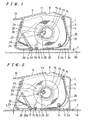
- FIG. 1 is a longitudinal sectional view of an adhesive tape adhering device according to an embodiment of the present invention immediately before an adhering operation in which state an inner case thereof is inclined forwardly;
- FIG. 2 is a longitudinal sectional view of the adhesive tape adhering device when an adhering operation of this embodiment has started;
- FIG. 3 is a longitudinal sectional view of the adhesive tape adhering device immediately before the inner case is returned slightly rearwardly by stressing of a leaf spring and the adhesive tape is cut by the cutting blade;
- FIG. 4 is a longitudinal sectional view of the adhesive tape adhering device in which the inner case has been completely returned rearwardly by the stress of the leaf spring and the cutting blade has moved to a lower portion of the pressing roller;
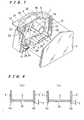
- FIG. 5 is a bottom view of the adhesive tape adhering device;
- FIG. 6 is a perspective view showing use of the adhesive tape adhering device;
- FIG. 7 is a partial exploded perspective view of the device; and
- FIG. 8 shows two alternative sectional views taken along a line A-A in Fig. 5.
-
- In the drawings,
reference number 1 represents an outer case,reference number 2 represents a tapered bottom plate,reference number 2a represents a bottom surface of the outer case,reference number 3 represents tape exit opening,reference numbers 4, 4' represent side wall plates,reference numbers 4a, 4'a represent lower end surfaces of straight lower end edges of the pair of left and right side wall plates,reference number 5 represents an inner case,reference number 6 represents an innercase rotation shaft 6,reference number 7 represents aslight distance 7 provided betweenlower end surfaces 4a, 4'a of straight lower end edges of the pair of left and rightside wall plates 4, 4' andbottom surfaces reference number 8 represents an upperopenings reference number 9 represents a fingertip engaging portion,reference number 10 represents a projecting piece,reference number 11 represents a tape core cylinder retaining member,reference number 12 represents an inner case side wall,reference number 13 represents a tape mounting shaft,reference number 14 represents a stopper,reference number 15 represents an adhesive tape,reference number 16 represents a tape core cylinder,reference number 17 represents a pressing roller,reference number 18 represents an adherend,reference number 19 represents a guide roller,reference number 20 represents a swinging plate,reference number 21 represents a swinging plate shaft,reference number 22 represents a cam hole,reference number 23 represents a pin,reference number 24 represents a supporting piece,reference number 25 represents a cutting blade,reference number 26 represents a cam hole,reference number 27 represents a man's hand,reference number 28 represents a front bottom plate,reference number 28a represents a bottom surface of the outer case,reference number 29 represents a leaf spring,reference number 30 represents a stopper and reference symbol a represents a tape end. - In Figs. 1 to 5, the
outer case 1 is provided with side wall plates 4(4'), one of which is openable or removable and a bottom surface of the case is provided with thetape exit opening 3 and anopening 8 above thetape exit opening 3. - The
inner case 5 and an innercase side wall 12, one side of which is open, are mounted such that they can longitudinally swing around arotation shaft 6 of the inner case fixed to a rear lower portion of theouter case 1. - The
inner case 5 comprises afingertip engaging portion 9 provided on a front upper portion of the innercase side wall 12, a projectingpiece 10 provided on a tip end of the innercase side wall 12, atape mounting shaft 13 on which the roll ofadhesive tape 15 can be mounted at a substantially central portion of the innercase side wall 12, apressing roller 17 mounted to a front bottom tip end of the innercase side wall 12 at right angles, and aguide roller 19 mounted to the innercase side wall 12 on an adhering surface of theadhesive tape 15 rearwardly of thepressing roller 17 for guiding theadhesive tape 15 dispensed from the roll ofadhesive tape 15 toward thepressing roller 17. - The
inner case 5 can be swung longitudinally by pressing on thefingertip engaging portion 9. Theinner case 5 includes astopper 14 which can be swung by thefingertip engaging portion 9 and afurther stopper 30 disposed on the bottom surface in theouter case 1. Theinner case 5 automatically returns rearward when the adhering operation is completed. - The
inner case 5 automatically returns rearwardly. It is fixed to a central portion of the side wall plate 4(4') of theouter case 1 at right angles thereto, and the rod-like tape corecylinder retaining member 11 passes through theoval cam hole 26 of theinner case 5 and pushes against an inner surface of the adhesivetape core cylinder 16 as a result of the rearward swinging operation of theinner case 5 under the influence of theleaf spring 29. - Further, there is provided a swinging
plate 20 between the side wall plate 4(4') of theouter case 1 and the innercase side wall 12. The swingingplate 20 is pivotally supported by the swingingplate shaft 21 fixed to the outercase side wall 4. Thepin 23 is fixed to an upper portion of the innercase side wall 12 and rearwardly of the swingingplate shaft 21 and engages with thecam hole 22 disposed in the swingingplate 20. Acutting blade 25 for cutting theadhesive tape 15 is provided on a lower end of the swingingplate 20 and on the supportingpiece 24 thereof. Thecutting blade 25 is retreated forwardly of thepressing roller 17 when theinner case 5 is forwardly inclined by the longitudinal swinging operation of thefingertip engaging portion 9, and the swingingplate 20 and the innercase side wall 12 are associatively moved so that thecutting blade 25 moves below the pressingroller 17 when theinner case 5 is inclined rearwardly. - In Fig. 1, the roll of
adhesive tape 15 is mounted on thetape mounting shaft 13, and the adhesive tape tip end a is pulled out. The projectingpiece 10 on the tip end of thefingertip engaging portion 9 is pushed and the adhesive tape tip end a is allowed to pass around an upper portion of theguide roller 19 and then is pulled out to an outer peripheral lower portion of thepressing roller 17. - To start the adhering operation, a rear portion lower side corner of the
outer case 1 is brought into contact with the adherend, and a front lower end surface of the side wall plate 4(4') of theouter case 1 is pushed against theadherend 18. - In Fig. 2, if the
outer case 1 is moved rearwardly while pushing thefingertip engaging portion 9 and the projectingpiece 10, theadhesive tape 15 is pushed by the pressingroller 17 and is reliably adhered to theadherend 18. - A front portion of the tapered
bottom plate 2 of theouter case 1 is situated on the same level as the lower end surfaces of the side wall plates 4(4'). Therefore, the surface of theadherend 18 is pushed immediately prior to the adhering of the tape thereto, and the adhering operation can accordingly be carried out more reliably. - In Fig. 3, if the adhering operation of the
adhesive tape 15 having a predetermined length has been completed, the pushing force on the projectingpiece 10 is released. As theinner case 5 is rotated rearwardly by the stress of theleaf spring 29, thecutting blade 25 and the supportingpiece 24 mounted on the tip end of the swingingplate 20 rotate in association with theinner case 5 and move below the lifted pressingroller 17. The cutting operation of theadhesive tape 15 is started. - As shown in Fig. 4, when the cutting operation of the
adhesive tape 15 has been completed and the front portion of theouter case 1 has been lifted, the supportingpiece 24 and thecutting blade 25 have moved below the pressing roller, and theadhesive tape 15 is ready for the next adhering operation since the adhesive tape tip end is left a on an outer peripheral surface lower portion of thepressing roller 17 with theadhesive tape 15 adhered to theguide roller 19. - At the same time, the tape core
cylinder retaining member 11 pushes against an inner surface of the adhesivetape core cylinder 16 by the rearward swinging operation of theinner case 5 under the action of the stress of theleaf spring 29, and idling or movement caused by vibration of the roll ofadhesive tape 15 is prevented. - A blade tip of the
cutting blade 25 fixed to the supportingpiece 24 is inclined as shown in Fig. 5, which makes it possible to cut theadhesive tape 15 from its edge easily. - As shown in Fig. 6, the projecting
piece 10 is formed with an upward bend at its front end which, together with thefingertip engaging portion 9 at a front upper portion of theinner case 5, is configured to fit the man'shand 27. Surfaces with which the man's hand are adapted to engage may be provided with bumps and dips so that the surface is not slippery. - As shown in Fig. 7, one side of the
outer case 1 is openable and the side wall plate 4' can be attached and detached by engaging means (not shown). - In Figs. 8a and
8b reference number 7 represents the small distance which is provided between thelower end surfaces 4a, 4'a of the straight lower edges of the pair of left and rightside wall plates 4, 4' and thebottom surfaces 2a (28a) of the outer case. Because of thissmall distance 7, thelower end surfaces 4a, 4'a of the straight lower edges of the pair of left and rightside wall plates 4, 4' function as rail-like guides, the adhesive tape adhering device can be easily moved in a straight line on the surface of theadherend 18 without deviating laterally, and it is accordingly possible to adhere theadhesive tape 15 thereon in a straight line. In Fig. 8(a), thelower end surfaces 4a, 4'a of theside wall plates 4, 4' are flat and stable. In Fig. 8(b), thelower end surfaces 4a, 4'a are substantially chamfered, and thelower end surfaces 4a, 4'a have reduced thickness, and the surfaces function as rail-like guides and lateral slip is even less likely to occur. - According to the present invention, the following effects can be exhibited.
- According to the invention as set out in
claims 1 to 3, an edge surface of the straight lower end edge of each of the pair of left and right side wall plates functions as the a guide, the adhesive tape adhering device moves easily in a straight line on the surface of the adherend without deviating laterally, and it is possible to easily adhere the adhesive tape in a straight line. - According to the invention as set out in
claim 5, a portion of the rear bottom surface of the tape exit opening of the outer case is situated in the same plane as that of the lower end surface of the side wall plates of the outer case. Therefore, the adherend immediately before it is pressed by the pressing roller will be held flat, and it is accordingly possible to reliably adhere the tape. - According to the invention as set out in
claim 6, the pressing roller passes through the tape exit opening by the forward swinging operation of the inner case, and the pressing roller projects from the lower end surface of the side wall plate. Therefore, the pressing roller can directly push on the adherend and reliably adhere the tape. - According to the invention as set out in
claim 7 the inner case is provided at its front upper portion with the fingertip engaging portion. Therefore, the device easily fits a man's hand and the adhering operation becomes easy. - According to the invention as set out in
claim 8 the outer case and the inner case are engaged or engageable with each other by means of the plate-like or coil-like spring between the stopper disposed on the bottom surface of the outer case and the stopper disposed on a rear end upper portion of the inner case side wall. Therefore, if the man's hand is relaxed when the adhering operation has been completed, the inner case is automatically inclined rearwardly, and the adhesive tape can be cut at the same time. - According to the invention as set out in
claim 9 the tape core cylinder retaining member pushes the adhesive tape core cylindrical surface by the rearward swinging operation of the inner case by the stress of the spring, and movement which may be caused by vibration or the like of the roll of adhesive tape can be prevented when the device is not being used. - According to the invention as set out in
claim 10 since the swinging plate and the inner case side wall are associatively moved, the cutting blade draws a substantially horizontal arc and cuts the adhesive tape by a slight swinging operation of the inner case, and excellent cutting efficiency can be obtained. - According to the invention as set out in
claim 11 since one side of the outer case is opened or openable, and the outer case has a detachable side wall plate, it is easy to attach and detach the roll of adhesive tape or empty core cylinder.
Claims (11)
- An adhesive tape adhering device in which adhesive tape (15) is discharged from an opening (3) in a lower or bottom surface (2a, 28a) of a casing (1), wherein straight lower end edges (4a) of a pair of left and right outer case side wall plates (4) extend (7) from the casing bottom surface (2a, 28a).
- A device according to claim 1 wherein the lower end edges (4a) extend by a small distance (7) from the casing bottom surface (2a, 28a).
- A device according to claim 1 or 2 wherein the lower end edges (4a) extend by 0.1 to 1.0 mm from the casing bottom surface (2a, 28a).
- An adhesive tape adhering device comprising an outer case (1) provided at its bottom surface (2a, 28a) with a tape exit opening (3), a pair of left and right side wall plates (4, 4'), an inner case (5) mounted such that the inner case (5) can longitudinally swing around an inner case rotation shaft (6) fixed to a lower portion of the outer case (5), the inner case (5) having a tape mounting shaft (13) on which a roll of adhesive tape (15) can be mounted, and an inner case side wall (12), a pressing roller (17) mounted to a front lower tip end of the inner case side wall (12) at right angles thereto, and a guide roller (19) mounted to the inner case side wall (12) on the adhering surface side of the adhesive tape (15) for guiding the adhesive tape (15) dispensed from the roll of adhesive tape (15) to the pressing roller (17), wherein there is a small distance (7) between the bottom surface (2a, 28a) of the outer case (1) and lower end surfaces of the side wall plates (4, 4').
- A device according to claim 4 wherein a portion of the bottom surface (2a) behind the tape exit opening (3) of the outer case (1) lies in the same plane as that of the lower end surfaces (4a, 4'a) of the side wall plates (4, 4') of the outer case (1).
- A device according to claim 4 or 5 wherein the pressing roller (17) passes through the tape exit opening (3) by a forward swinging operation of the inner case (5), and projects from the lower end surface (2a, 28a) of the side wall plates (4, 4').
- A device according to any one of claims 4 to 6 wherein the inner case (5) is provided at its front upper portion with a fingertip engaging portion (9, 10).
- A device according to any one of claims 4 to 7, wherein the outer case (1) and the inner case (5) are engaged or engageable with each other by means of a first stopper (30) disposed on a bottom surface (2a) of the outer case (1) and a second stopper (14) disposed on a rear upper portion of the inner case side wall (12) and by means of a plate-like or coil-like spring (29).
- A device according to any one of claims 4 to 8, further comprising a rod-like tape core cylinder retaining member (11) which is fixed to a central portion of the side wall plate (4) of the outer case (1) at right angles thereto and which passes through an oval or elongate cam hole (26) formed in the inner case (5), wherein the tape core cylinder retaining member (11) pushes an adhesive tape core (16) cylindrical inner surface as a result of rearward swinging movement of the inner case (5) caused by stress of the spring (29).
- A device according to any one of claims 4 to 9, further comprising a swinging plate (20) between one of the side wall plates (4) of the outer case (1) and the inner case side walls (12), wherein the swinging plate (20) is pivotally mounted to a swinging plate shaft (21) fixed to the outer case side wall (4), a pin (23) fixed to the inner case side wall (12) engages with a cam hole (22) formed in a rear portion of the swinging plate (20), a lateral supporting piece (24) at a lower end of the swinging plate (20) is provided with a cutting blade (25) for cutting the adhesive tape (15), the swinging plate (20) and the inner case side wall (4) are associatively moved such that the cutting blade (25) is retreated forwardly of the pressing roller (17) when the inner case (5) is forwardly inclined by the longitudinal swinging operation of the fingertip engaging portion (9, 10), and the cutting blade (25) moves below the lifted pressing roller (17) when the inner case (5) is rearwardly inclined.
- A device according to any one of claims 4 to 10, wherein the outer case (1) has one openable side and one of the side wall plates (4') is attachable to and detachable from the openable side.
Applications Claiming Priority (2)
| Application Number | Priority Date | Filing Date | Title |
|---|---|---|---|
| JP2001232938 | 2001-07-31 | ||
| JP2001232938A JP3753030B2 (en) | 2001-07-31 | 2001-07-31 | Adhesive tape sticking device |
Publications (2)
| Publication Number | Publication Date |
|---|---|
| EP1281652A2 true EP1281652A2 (en) | 2003-02-05 |
| EP1281652A3 EP1281652A3 (en) | 2005-01-19 |
Family
ID=19064777
Family Applications (1)
| Application Number | Title | Priority Date | Filing Date |
|---|---|---|---|
| EP02255298A Withdrawn EP1281652A3 (en) | 2001-07-31 | 2002-07-30 | Adhesive tape adhering device |
Country Status (6)
| Country | Link |
|---|---|
| US (1) | US6896025B2 (en) |
| EP (1) | EP1281652A3 (en) |
| JP (1) | JP3753030B2 (en) |
| KR (1) | KR100595957B1 (en) |
| CN (1) | CN1241809C (en) |
| TW (1) | TW568876B (en) |
Cited By (3)
| Publication number | Priority date | Publication date | Assignee | Title |
|---|---|---|---|---|
| DE102004043367A1 (en) * | 2004-09-08 | 2006-03-09 | Henkel Kgaa | Device for dispensing adhesive tape |
| CN102433076A (en) * | 2011-09-07 | 2012-05-02 | 北京世东凌云汽车饰件有限公司 | Adhesive tape sticking device |
| CN113954566A (en) * | 2021-09-15 | 2022-01-21 | 马光跃 | Wall cloth laying auxiliary device suitable for external corner wall |
Families Citing this family (11)
| Publication number | Priority date | Publication date | Assignee | Title |
|---|---|---|---|---|
| US6808586B1 (en) * | 2003-06-10 | 2004-10-26 | The Procter & Gamble Company | Applicator for and method of applying a sheet material to a substrate |
| US20050284583A1 (en) * | 2004-06-29 | 2005-12-29 | Soyad Tony T | One handed spool and roller tape dispenser |
| US7320351B2 (en) * | 2005-02-25 | 2008-01-22 | Huah Jinn Tape Searching Co., Ltd. | Tape cutter |
| US7441580B2 (en) * | 2005-08-03 | 2008-10-28 | Jasdi Magnet Co., Ltd | Magnetic adhesive tape holder |
| TWI385035B (en) * | 2007-05-25 | 2013-02-11 | Hon Hai Prec Ind Co Ltd | Cleaning device |
| US20090039100A1 (en) * | 2007-08-10 | 2009-02-12 | James King | Hand-held bandage dispenser |
| CA2796945C (en) | 2010-04-23 | 2018-05-15 | 3M Innovative Properties Company | Adhesive tape dispenser for single hand operation |
| JP6638569B2 (en) * | 2016-06-15 | 2020-01-29 | マックス株式会社 | Gardening binding machine |
| US11142366B2 (en) * | 2018-10-23 | 2021-10-12 | Blutaper, Llc | Adhesive tape dispenser with puncturing blade |
| WO2021030601A1 (en) * | 2019-08-13 | 2021-02-18 | Ferrara Candy Company | Dispenser for use with an elongated edible confection |
| CN111135375B (en) * | 2020-02-05 | 2021-10-22 | 刘封 | Wound warning tape processing apparatus for oncology department infusion port |
Citations (2)
| Publication number | Priority date | Publication date | Assignee | Title |
|---|---|---|---|---|
| CH523194A (en) * | 1970-04-17 | 1972-05-31 | Weick Heinz Hermann | Hand-held device for applying adhesive tape |
| JPH0781827A (en) * | 1993-09-10 | 1995-03-28 | Sakae Urushizaki | Adhesive tape attaching tool |
Family Cites Families (9)
| Publication number | Priority date | Publication date | Assignee | Title |
|---|---|---|---|---|
| US2493737A (en) * | 1946-07-02 | 1950-01-10 | Burns Bruce | Device for applying adhesive tape |
| DE2105023C3 (en) * | 1970-02-16 | 1974-03-14 | Weick, Heinz Hermann, Genf (Schweiz) | Hand-held device for applying adhesive tape |
| JPS5522048Y2 (en) * | 1977-03-09 | 1980-05-27 | ||
| JPS5718548U (en) * | 1980-07-04 | 1982-01-30 | ||
| KR870003230Y1 (en) * | 1985-07-09 | 1987-09-26 | 하유식 | Scotch tape holder |
| JPS6392569A (en) | 1986-10-02 | 1988-04-23 | Sakae Urushizaki | Tape cutter |
| KR910007819Y1 (en) * | 1988-07-22 | 1991-10-05 | 박선동 | Stopper of tape cutter |
| JP3079216U (en) * | 2000-11-07 | 2001-08-10 | 孝男 西本 | Adhesive tape pasting tool |
| KR100725092B1 (en) * | 2000-12-07 | 2007-06-04 | 삼성전자주식회사 | Apparatus for sensing signal lines in chip of semiconductor memory device |
-
2001
- 2001-07-31 JP JP2001232938A patent/JP3753030B2/en not_active Expired - Fee Related
- 2001-11-30 CN CNB011424931A patent/CN1241809C/en not_active Expired - Fee Related
-
2002
- 2002-07-25 TW TW091116538A patent/TW568876B/en not_active IP Right Cessation
- 2002-07-30 KR KR1020020044874A patent/KR100595957B1/en not_active IP Right Cessation
- 2002-07-30 US US10/207,270 patent/US6896025B2/en not_active Expired - Fee Related
- 2002-07-30 EP EP02255298A patent/EP1281652A3/en not_active Withdrawn
Patent Citations (2)
| Publication number | Priority date | Publication date | Assignee | Title |
|---|---|---|---|---|
| CH523194A (en) * | 1970-04-17 | 1972-05-31 | Weick Heinz Hermann | Hand-held device for applying adhesive tape |
| JPH0781827A (en) * | 1993-09-10 | 1995-03-28 | Sakae Urushizaki | Adhesive tape attaching tool |
Non-Patent Citations (1)
| Title |
|---|
| PATENT ABSTRACTS OF JAPAN vol. 1995, no. 06, 31 July 1995 (1995-07-31) -& JP 07 081827 A (SAKAE URUSHIZAKI), 28 March 1995 (1995-03-28) * |
Cited By (3)
| Publication number | Priority date | Publication date | Assignee | Title |
|---|---|---|---|---|
| DE102004043367A1 (en) * | 2004-09-08 | 2006-03-09 | Henkel Kgaa | Device for dispensing adhesive tape |
| CN102433076A (en) * | 2011-09-07 | 2012-05-02 | 北京世东凌云汽车饰件有限公司 | Adhesive tape sticking device |
| CN113954566A (en) * | 2021-09-15 | 2022-01-21 | 马光跃 | Wall cloth laying auxiliary device suitable for external corner wall |
Also Published As
| Publication number | Publication date |
|---|---|
| TW568876B (en) | 2004-01-01 |
| US20030024651A1 (en) | 2003-02-06 |
| JP2003040518A (en) | 2003-02-13 |
| US6896025B2 (en) | 2005-05-24 |
| KR100595957B1 (en) | 2006-07-03 |
| CN1400152A (en) | 2003-03-05 |
| EP1281652A3 (en) | 2005-01-19 |
| KR20030011679A (en) | 2003-02-11 |
| JP3753030B2 (en) | 2006-03-08 |
| CN1241809C (en) | 2006-02-15 |
Similar Documents
| Publication | Publication Date | Title |
|---|---|---|
| EP1281652A2 (en) | Adhesive tape adhering device | |
| TWI490157B (en) | Adhesive tape dispenser for single hand operation | |
| US7320351B2 (en) | Tape cutter | |
| US4486263A (en) | Support for a tape which is adhesive on one or both of its faces | |
| EP1054832B1 (en) | An adhesive tape case | |
| US20080083487A1 (en) | Automatic tape dispenser | |
| EP0509076B1 (en) | Tape dispensers | |
| FR2530845A1 (en) | DATA READING DEVICE FOR DATA PROCESSING APPARATUS | |
| US8656976B2 (en) | Switching dual cam adhesive tape dispenser | |
| US4344813A (en) | Tape dispenser | |
| EP0270736B1 (en) | Portable dispenser for applying a transfer adhesive | |
| FR2555135A1 (en) | METHOD AND APPARATUS FOR FIXING LABELS, AND LABEL FEEDING MECHANISM | |
| EP0060636B1 (en) | Splicing apparatus and cassette therefor | |
| KR100355548B1 (en) | An adhesive tape case | |
| JP2018150160A (en) | Tape cutter | |
| EP1609723B1 (en) | Labeling tool | |
| JP2997880B2 (en) | Storage case for adhesive tape | |
| JP3529833B2 (en) | Tape sticking device | |
| JP2000250413A (en) | Peeling device | |
| JP3101084U (en) | Tape cutter | |
| JPH10109498A (en) | Feeding type eraser holder | |
| KR100211632B1 (en) | Automatic cutting apparatus for adhesive tape | |
| JP2000001254A (en) | Storing case for adhesive tape | |
| JP2000246685A (en) | Cutter edge and roll paper cutting device or thermal printer using thereof | |
| JP2000327206A (en) | Tape holder |
Legal Events
| Date | Code | Title | Description |
|---|---|---|---|
| PUAI | Public reference made under article 153(3) epc to a published international application that has entered the european phase |
Free format text: ORIGINAL CODE: 0009012 |
|
| AK | Designated contracting states |
Designated state(s): AT BE BG CH CY CZ DE DK EE ES FI FR GB GR IE IT LI LU MC NL PT SE SK TR |
|
| AX | Request for extension of the european patent |
Extension state: AL LT LV MK RO SI |
|
| PUAL | Search report despatched |
Free format text: ORIGINAL CODE: 0009013 |
|
| AK | Designated contracting states |
Kind code of ref document: A3 Designated state(s): AT BE BG CH CY CZ DE DK EE ES FI FR GB GR IE IT LI LU MC NL PT SE SK TR |
|
| AX | Request for extension of the european patent |
Extension state: AL LT LV MK RO SI |
|
| 17P | Request for examination filed |
Effective date: 20050701 |
|
| AKX | Designation fees paid |
Designated state(s): DE FR GB IT |
|
| 17Q | First examination report despatched |
Effective date: 20080707 |
|
| STAA | Information on the status of an ep patent application or granted ep patent |
Free format text: STATUS: THE APPLICATION IS DEEMED TO BE WITHDRAWN |
|
| 18D | Application deemed to be withdrawn |
Effective date: 20081118 |