EP3533618B1 - Positioning device for an ink pad container - Google Patents
Positioning device for an ink pad container Download PDFInfo
- Publication number
- EP3533618B1 EP3533618B1 EP18191665.1A EP18191665A EP3533618B1 EP 3533618 B1 EP3533618 B1 EP 3533618B1 EP 18191665 A EP18191665 A EP 18191665A EP 3533618 B1 EP3533618 B1 EP 3533618B1
- Authority
- EP
- European Patent Office
- Prior art keywords
- ink pad
- pad container
- positioning
- positioning device
- receiving space
- Prior art date
- Legal status (The legal status is an assumption and is not a legal conclusion. Google has not performed a legal analysis and makes no representation as to the accuracy of the status listed.)
- Active
Links
- 238000010186 staining Methods 0.000 description 1
Images


Classifications
-
- B—PERFORMING OPERATIONS; TRANSPORTING
- B41—PRINTING; LINING MACHINES; TYPEWRITERS; STAMPS
- B41K—STAMPS; STAMPING OR NUMBERING APPARATUS OR DEVICES
- B41K1/00—Portable hand-operated devices without means for supporting or locating the articles to be stamped, i.e. hand stamps; Inking devices or other accessories therefor
- B41K1/36—Details
- B41K1/38—Inking devices; Stamping surfaces
- B41K1/54—Inking pads
-
- B—PERFORMING OPERATIONS; TRANSPORTING
- B41—PRINTING; LINING MACHINES; TYPEWRITERS; STAMPS
- B41K—STAMPS; STAMPING OR NUMBERING APPARATUS OR DEVICES
- B41K1/00—Portable hand-operated devices without means for supporting or locating the articles to be stamped, i.e. hand stamps; Inking devices or other accessories therefor
- B41K1/36—Details
- B41K1/38—Inking devices; Stamping surfaces
- B41K1/40—Inking devices operated by stamping movement
- B41K1/42—Inking devices operated by stamping movement with pads or rollers movable for inking
Definitions
- the present invention relates to a positioning device for an ink pad container, and more particularly to a positioning device that may improve the positioning stability of the ink pad container.
- a conventional positioning device for an ink pad container has a body 90.
- the body 90 has a front surface, a rear surface, two side surfaces, a receiving space 91, a front opening 92, a rear opening 93, and two positioning protrusions 94.
- the receiving space 91 is formed in the body 90.
- the front opening 92 is formed on the front surface of the body 90 and communicates with the receiving space 91.
- the rear opening 93 is formed on the rear surface of the body 90 and communicates with the receiving space 91.
- the two positioning protrusions 94 are respectively formed on the two side surfaces of the body 90 and are inserted into the receiving space 91.
- the conventional positioning device can be disposed on a housing of a stamp for an ink pad container 80 to be inserted therein.
- the ink pad container 80 has two side surfaces. In each one of the two side surfaces of the ink pad container 80, two longitudinal ribs 81 are formed on and extend out of the side surface of the ink pad container 80 at a spaced interval.
- a positioning groove 82 is formed on the side surface of the ink pad container 80 and is located between the two longitudinal ribs 81.
- the ink pad container 80 can be inserted into the receiving space 91 of the body 90 via the front opening 92 or the rear opening 93.
- the positioning protrusions 94 are respectively inserted into the positioning grooves 82 of the ink pad container 80 to position the ink pad container 80 in the body 90.
- the positioning protrusions 94 of the body 90 are fixed. Before each one of the two positioning protrusions 94 is inserted into a corresponding one of the positioning grooves 82, the positioning protrusion 94 has to pass through one of the two longitudinal ribs 81. After the positioning protrusion 94 is inserted into the corresponding positioning groove 82, a gap 70 is formed between the positioning protrusion 94 and the adjacent longitudinal ribs 81. The positioning protrusion 94 cannot abut against the adjacent longitudinal ribs 81. Therefore, the ink pad container 80 has a moveable allowance and cannot be steadily positioned in the body 90. The ink pad container 80 may be swayed to deviation. A printing surface of the stamp cannot be completely pressed on an ink pad 83 of the ink pad container 80. Ink stained on the printing surface is not distributed evenly, which also makes a stamped pattern unclear.
- a protruding height of each one of the positioning protrusion 94 may be increased for firm abutment. Then, the ink pad container 80 is hard to be inserted into or pressed out of the body 90. Size settings of the ink pad container 80 and the body 90 can hardly simultaneously satisfy the requirements for ease in assembly and for the positioning stability.
- another conventional positioning device is disclosed in WO 2005/084953 A2 .
- the present invention provides a positioning device for an ink pad container to mitigate or obviate the aforementioned problems.
- the objective of the invention is to provide a positioning device for an ink pad container that can solve the shortcoming that the conventional positioning device cannot fix the ink pad container well, and cannot simultaneously satisfy the requirements for ease in assembly and for the positioning stability.
- the positioning device for an ink pad container has a body and two elastic sheets.
- the body has a receiving space, a front side surface, a rear side surface, two lateral side surfaces, a front opening, a rear opening, and two through grooves.
- the receiving space is formed in the body.
- the lateral side surfaces are opposite to each other.
- the front opening is formed through the front side surface of the body and communicates with the receiving space.
- the rear opening is formed through the rear side surface of the body and communicates with the receiving space.
- the two through grooves are respectively formed through the two lateral side surfaces of the body and both communicate with the receiving space.
- the two elastic sheets are respectively formed on the two lateral side surfaces of the body. Each one of the two elastic sheets has an arm and a positioning protrusion.
- the arm is formed on a corresponding one of the two lateral side surfaces of the body, is inserted into a corresponding one of the two through grooves, and has an inner side surface.
- the positioning protrusion is formed on the inner side surface of the arm and is inserted into the receiving space of the body.
- An ink pad container may be inserted into the receiving space of the positioning device via the front opening or the rear opening.
- the ink pad container has two outer surfaces and two positioning members. The outer surfaces are opposite to each other.
- the two positioning members are respectively disposed on the two outer surfaces of the ink pad container.
- Each one of the two positioning members has two longitudinal ribs and a positioning groove.
- the longitudinal ribs are formed on and protrude out of the outer surface of the ink pad container.
- the positioning groove is formed on the outer surface of the ink pad container and is located between the two longitudinal ribs.
- the ink pad container passes between the two elastic sheets, one of the two longitudinal ribs passes through the positioning protrusion of a corresponding one of the two elastic sheets and pushes the corresponding arm outwardly, and then the positioning protrusion is inserted into the positioning groove.
- the positioning protrusion is pressed by a resilience of the corresponding one of the two elastic sheets to abut the two longitudinal ribs.
- the positioning protrusion is in contact with the two longitudinal ribs for maintaining a positioning situation.
- the ink pad container After the ink pad container is inserted into the body for positioning, the ink pad container does not have a moveable allowance to move. Therefore, the ink pad container can be firmly positioned in the body, and the positioning stability of the ink pad container is increased.
- a printing surface of a stamp can be pressed on an ink pad in the ink pad container completely. Ink stained on the printing surface is distributed evenly, which also makes a stamped pattern clear.
- the tolerance allowances of the positioning device and the ink pad container are increased by the resiliences of the two elastic sheets.
- the ink pad container is firmly disposed in the positioning device. Therefore, the positioning device can simultaneously satisfy the requirements for ease in assembly and for the positioning stability.
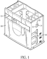
- a positioning device for an ink pad container in accordance with the present invention has a body 10 and two elastic sheets 20.
- the body 10 has a receiving space 11, a front side surface, a rear side surface, two lateral side surfaces, a front opening 12, a rear opening 13, and two through grooves 14.
- the receiving space 11 is formed in the body 10.
- the lateral side surfaces are opposite to each other.
- the front opening 12 is formed through the front side surface of the body 10 and communicates with the receiving space 11.
- the rear opening 13 is formed through the rear side surface of the body 10 and communicates with the receiving space 11.
- the two through grooves 14 are respectively formed through the two lateral side surfaces of the body 10 and both communicate with the receiving space 11.
- the elastic sheets 20 are respectively formed on the two lateral side surfaces of the body 10.
- Each one of the two elastic sheets 20 has an arm 21 and a positioning protrusion 22.
- the arm 21 is formed on a corresponding one of the two lateral side surfaces of the body 10, is inserted into a corresponding one of the two through grooves 14, and has an inner side surface.
- the positioning protrusion 22 is formed on the inner side surface of the arm 21 and is inserted into the receiving space 11 of the body 10.
- the body 10 has an inner top surface and a guiding groove 15.
- the guiding groove 15 is formed on the inner top surface of the body 10 and has a front end and a rear end.
- the front end of the guiding groove 15 faces the front opening 12 of the body 10.
- the rear end of the guiding groove 15 faces the rear opening 13 of the body 10.
- the body 10 has two longitudinal grooves 16.
- the two longitudinal grooves 16 are respectively formed through the two lateral side surfaces of the body 10 and are located below the two through grooves 14 respectively.
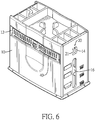
- the positioning device is disposed in a housing 31 of a stamp 30 for an ink pad container 40 to be inserted therein.
- the ink pad container 40 has two outer surfaces and two positioning members. The outer surfaces of the ink pad container 40 are opposite to each other.
- the two positioning members of the ink pad container 40 are respectively disposed on the two outer surfaces of the ink pad container 40.
- Each one of the two positioning members of the ink pad container 40 has two longitudinal ribs 41 and a positioning groove 42.
- the longitudinal ribs 41 are formed on and protrude out of the outer surface of the ink pad container 40.
- the positioning groove 42 is formed on the outer surface of the ink pad container 40 and is located between the two longitudinal ribs 41.
- the ink pad container 40 can be inserted into the receiving space 11 of the body 10 via the front opening 12 or the rear opening 13 of the body 10.
- the ink pad container 40 is inserted between the two elastic sheets 20.
- the arms 21 of the two elastic sheets 20 are pushed by the passing longitudinal ribs 41 for moving outwardly.
- the positioning protrusions 22 can be respectively inserted into the positioning grooves 42 by the rebounds of the elastic sheets 20.
- Each one of the positioning protrusions 22 abuts against the two adjacent longitudinal ribs 41. Therefore, the two elastic sheets 20 abut against the ink pad container 40 for clipping the ink pad container 40 to position the ink pad container 40.
- the longitudinal ribs 41 of the ink pad container 40 are passed through the positioning protrusions 22 of the two elastic sheets 20.
- the positioning protrusions 22 are outwardly pushed by the longitudinal ribs 41 due to the arms 21.
- the longitudinal ribs 41 can pass through the positioning protrusions 22 smoothly.
- the ink pad container 40 is easy to be pressed out of the body 10.
- the ink pad container 40 has a top surface and multiple guiding elements 43.
- the guiding elements 43 are disposed on the top surface of the ink pad container 40. When the ink pad container 40 is inserted into the body 10, the guiding elements 43 can be guided by the guiding groove 15, and the ink pad container 40 can be easily inserted into the body 10.
- each one of the positioning protrusions 22 abuts against the two adjacent longitudinal ribs 41 of the ink pad container 40 by a resilience provided by the arm 21 of the corresponding one of the two elastic sheets 20.
- the positions of the two positioning protrusions 20 can be suitably adjusted by the arms 21 for abutting against the longitudinal ribs 41 of the ink pad container 40.
- the ink pad container 40 can be positioned in the body 10 securely. After the ink pad container 40 is positioned in the body 10, the ink pad container 40 does not have a moveable allowance to move. Therefore, the ink pad container 40 can be firmly positioned in the body 10.
- a printing surface of the stamp 30 can be pressed on an ink pad 44 in the ink pad container 40 for completely staining ink in the ink pad 44 to make a clear stamped pattern.
- the ink pad container 40 is positioned in the body 10 by the two elastic sheets 20.
- the two elastic sheets 20 have the resiliences. Requirement for the size accuracy of the positioning device and the size accuracy of the ink pad container 40 can be less strict.
- the tolerance allowances of the positioning device and the ink pad container 40 are increased, and the positioning stability of the ink pad container 40 is increased simultaneously.
- the ink pad container 40 is easy to be disposed into and pushed out of the positioning device. Therefore, the positioning device can simultaneously satisfy the requirements for ease in assembly and for the positioning stability.
Description
- This application claims the benefit of Taiwan patent application No.
107202798, filed on March 2, 2018 - The present invention relates to a positioning device for an ink pad container, and more particularly to a positioning device that may improve the positioning stability of the ink pad container.
- With reference to
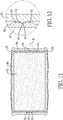
Figs. 11 and 12 , a conventional positioning device for an ink pad container has abody 90. Thebody 90 has a front surface, a rear surface, two side surfaces, areceiving space 91, afront opening 92, arear opening 93, and twopositioning protrusions 94. Thereceiving space 91 is formed in thebody 90. Thefront opening 92 is formed on the front surface of thebody 90 and communicates with thereceiving space 91. Therear opening 93 is formed on the rear surface of thebody 90 and communicates with thereceiving space 91. The twopositioning protrusions 94 are respectively formed on the two side surfaces of thebody 90 and are inserted into thereceiving space 91. - In use, the conventional positioning device can be disposed on a housing of a stamp for an
ink pad container 80 to be inserted therein. Theink pad container 80 has two side surfaces. In each one of the two side surfaces of theink pad container 80, twolongitudinal ribs 81 are formed on and extend out of the side surface of theink pad container 80 at a spaced interval. Apositioning groove 82 is formed on the side surface of theink pad container 80 and is located between the twolongitudinal ribs 81. Theink pad container 80 can be inserted into thereceiving space 91 of thebody 90 via the front opening 92 or therear opening 93. Thepositioning protrusions 94 are respectively inserted into thepositioning grooves 82 of theink pad container 80 to position theink pad container 80 in thebody 90. - Sizes and locations of the
positioning protrusions 94 of thebody 90 are fixed. Before each one of the twopositioning protrusions 94 is inserted into a corresponding one of thepositioning grooves 82, thepositioning protrusion 94 has to pass through one of the twolongitudinal ribs 81. After thepositioning protrusion 94 is inserted into thecorresponding positioning groove 82, agap 70 is formed between thepositioning protrusion 94 and the adjacentlongitudinal ribs 81. Thepositioning protrusion 94 cannot abut against the adjacentlongitudinal ribs 81. Therefore, theink pad container 80 has a moveable allowance and cannot be steadily positioned in thebody 90. Theink pad container 80 may be swayed to deviation. A printing surface of the stamp cannot be completely pressed on anink pad 83 of theink pad container 80. Ink stained on the printing surface is not distributed evenly, which also makes a stamped pattern unclear. - For increasing the positioning stability of the
ink pad container 80, a protruding height of each one of thepositioning protrusion 94 may be increased for firm abutment. Then, theink pad container 80 is hard to be inserted into or pressed out of thebody 90. Size settings of theink pad container 80 and thebody 90 can hardly simultaneously satisfy the requirements for ease in assembly and for the positioning stability. In addition, another conventional positioning device is disclosed inWO 2005/084953 A2 . - To overcome the shortcomings, the present invention provides a positioning device for an ink pad container to mitigate or obviate the aforementioned problems.
- The objective of the invention is to provide a positioning device for an ink pad container that can solve the shortcoming that the conventional positioning device cannot fix the ink pad container well, and cannot simultaneously satisfy the requirements for ease in assembly and for the positioning stability.
- The positioning device for an ink pad container has a body and two elastic sheets. The body has a receiving space, a front side surface, a rear side surface, two lateral side surfaces, a front opening, a rear opening, and two through grooves. The receiving space is formed in the body. The lateral side surfaces are opposite to each other. The front opening is formed through the front side surface of the body and communicates with the receiving space. The rear opening is formed through the rear side surface of the body and communicates with the receiving space. The two through grooves are respectively formed through the two lateral side surfaces of the body and both communicate with the receiving space. The two elastic sheets are respectively formed on the two lateral side surfaces of the body. Each one of the two elastic sheets has an arm and a positioning protrusion. The arm is formed on a corresponding one of the two lateral side surfaces of the body, is inserted into a corresponding one of the two through grooves, and has an inner side surface. The positioning protrusion is formed on the inner side surface of the arm and is inserted into the receiving space of the body.
- An ink pad container may be inserted into the receiving space of the positioning device via the front opening or the rear opening. The ink pad container has two outer surfaces and two positioning members. The outer surfaces are opposite to each other. The two positioning members are respectively disposed on the two outer surfaces of the ink pad container. Each one of the two positioning members has two longitudinal ribs and a positioning groove. The longitudinal ribs are formed on and protrude out of the outer surface of the ink pad container. The positioning groove is formed on the outer surface of the ink pad container and is located between the two longitudinal ribs.
- When the ink pad container passes between the two elastic sheets, one of the two longitudinal ribs passes through the positioning protrusion of a corresponding one of the two elastic sheets and pushes the corresponding arm outwardly, and then the positioning protrusion is inserted into the positioning groove. The positioning protrusion is pressed by a resilience of the corresponding one of the two elastic sheets to abut the two longitudinal ribs. The positioning protrusion is in contact with the two longitudinal ribs for maintaining a positioning situation. After the ink pad container is inserted into the body for positioning, the ink pad container does not have a moveable allowance to move. Therefore, the ink pad container can be firmly positioned in the body, and the positioning stability of the ink pad container is increased. A printing surface of a stamp can be pressed on an ink pad in the ink pad container completely. Ink stained on the printing surface is distributed evenly, which also makes a stamped pattern clear. In addition, the tolerance allowances of the positioning device and the ink pad container are increased by the resiliences of the two elastic sheets. The ink pad container is firmly disposed in the positioning device. Therefore, the positioning device can simultaneously satisfy the requirements for ease in assembly and for the positioning stability.
-
-
Fig. 1 is a perspective view of a positioning device for an ink pad container in accordance with the present invention; -
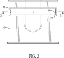
Fig. 2 is a front side view of the positioning device inFig. 1 ; -
Fig. 3 is a cross sectional side view of the positioning device along line 3-3 inFig. 2 ; -
Fig. 4 is an operational perspective view of the positioning device inFig. 1 , showing the positioning device is disposed in a housing; -
Fig. 5 is an exploded perspective view of the positioning device inFig. 4 , showing an ink pad container is not disposed into the positioning device yet; -
Fig. 6 is a perspective view of the positioning device inFig. 4 , showing the ink pad container is disposed into the positioning device; -
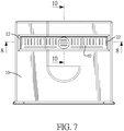
Fig. 7 is a front side view of the positioning device inFig. 6 ; -
Fig. 8 is a cross sectional side view of the positioning device along line 8-8 inFig. 7 ; -
Fig. 9 is an enlarged cross sectional side view of the positioning device inFig. 8 ; -
Fig. 10 is a cross sectional side view of the positioning device along line 10-10 inFig. 7 ; -
Fig. 11 is a cross sectional side view of a conventional positioning device in accordance with the prior art combined with an ink pad container; and -
Fig. 12 is an enlarged cross sectional side view of the conventional positioning device inFig. 11 . - With reference to
Figs. 1 to 3 , a positioning device for an ink pad container in accordance with the present invention has abody 10 and twoelastic sheets 20. - The
body 10 has a receivingspace 11, a front side surface, a rear side surface, two lateral side surfaces, afront opening 12, arear opening 13, and two throughgrooves 14. The receivingspace 11 is formed in thebody 10. The lateral side surfaces are opposite to each other. Thefront opening 12 is formed through the front side surface of thebody 10 and communicates with the receivingspace 11. Therear opening 13 is formed through the rear side surface of thebody 10 and communicates with the receivingspace 11. The two throughgrooves 14 are respectively formed through the two lateral side surfaces of thebody 10 and both communicate with the receivingspace 11. - The
elastic sheets 20 are respectively formed on the two lateral side surfaces of thebody 10. Each one of the twoelastic sheets 20 has anarm 21 and apositioning protrusion 22. Thearm 21 is formed on a corresponding one of the two lateral side surfaces of thebody 10, is inserted into a corresponding one of the two throughgrooves 14, and has an inner side surface. Thepositioning protrusion 22 is formed on the inner side surface of thearm 21 and is inserted into the receivingspace 11 of thebody 10. - With reference to
Fig. 3 , thebody 10 has an inner top surface and a guidinggroove 15. The guidinggroove 15 is formed on the inner top surface of thebody 10 and has a front end and a rear end. The front end of the guidinggroove 15 faces thefront opening 12 of thebody 10. The rear end of the guidinggroove 15 faces therear opening 13 of thebody 10. With reference toFig. 1 , thebody 10 has twolongitudinal grooves 16. The twolongitudinal grooves 16 are respectively formed through the two lateral side surfaces of thebody 10 and are located below the two throughgrooves 14 respectively. - With reference to
Figs. 4 to 7 , the positioning device is disposed in ahousing 31 of astamp 30 for anink pad container 40 to be inserted therein. Theink pad container 40 has two outer surfaces and two positioning members. The outer surfaces of theink pad container 40 are opposite to each other. The two positioning members of theink pad container 40 are respectively disposed on the two outer surfaces of theink pad container 40. Each one of the two positioning members of theink pad container 40 has twolongitudinal ribs 41 and apositioning groove 42. Thelongitudinal ribs 41 are formed on and protrude out of the outer surface of theink pad container 40. Thepositioning groove 42 is formed on the outer surface of theink pad container 40 and is located between the twolongitudinal ribs 41. - With reference to
Fig. 8 , theink pad container 40 can be inserted into the receivingspace 11 of thebody 10 via thefront opening 12 or therear opening 13 of thebody 10. Theink pad container 40 is inserted between the twoelastic sheets 20. Thearms 21 of the twoelastic sheets 20 are pushed by the passinglongitudinal ribs 41 for moving outwardly. The positioning protrusions 22 can be respectively inserted into thepositioning grooves 42 by the rebounds of theelastic sheets 20. Each one of thepositioning protrusions 22 abuts against the two adjacentlongitudinal ribs 41. Therefore, the twoelastic sheets 20 abut against theink pad container 40 for clipping theink pad container 40 to position theink pad container 40. - When the two
longitudinal ribs 41 of each one of the positioning members are close to a corresponding one of the twoelastic sheets 20, one of the twolongitudinal ribs 41 passes through thepositioning protrusion 22 of the correspondingelastic sheet 20 and pushes thepositioning protrusion 22 and thearm 21 of the correspondingelastic sheet 20 outwardly. Then, thepositioning protrusion 22 is inserted into thecorresponding positioning groove 42 and abuts against the two adjacentlongitudinal ribs 41. - For pressing the
ink pad container 40 to move out of thebody 10, thelongitudinal ribs 41 of theink pad container 40 are passed through the positioningprotrusions 22 of the twoelastic sheets 20. The positioning protrusions 22 are outwardly pushed by thelongitudinal ribs 41 due to thearms 21. Thelongitudinal ribs 41 can pass through the positioningprotrusions 22 smoothly. Theink pad container 40 is easy to be pressed out of thebody 10. - With reference to
Fig. 9 , theink pad container 40 has a top surface and multiple guidingelements 43. The guidingelements 43 are disposed on the top surface of theink pad container 40. When theink pad container 40 is inserted into thebody 10, the guidingelements 43 can be guided by the guidinggroove 15, and theink pad container 40 can be easily inserted into thebody 10. - Accordingly, each one of the
positioning protrusions 22 abuts against the two adjacentlongitudinal ribs 41 of theink pad container 40 by a resilience provided by thearm 21 of the corresponding one of the twoelastic sheets 20. Even though theink pad containers 40 inserted into thebody 10 have slight differences in size, the positions of the twopositioning protrusions 20 can be suitably adjusted by thearms 21 for abutting against thelongitudinal ribs 41 of theink pad container 40. Theink pad container 40 can be positioned in thebody 10 securely. After theink pad container 40 is positioned in thebody 10, theink pad container 40 does not have a moveable allowance to move. Therefore, theink pad container 40 can be firmly positioned in thebody 10. A printing surface of thestamp 30 can be pressed on anink pad 44 in theink pad container 40 for completely staining ink in theink pad 44 to make a clear stamped pattern. - The
ink pad container 40 is positioned in thebody 10 by the twoelastic sheets 20. The twoelastic sheets 20 have the resiliences. Requirement for the size accuracy of the positioning device and the size accuracy of theink pad container 40 can be less strict. The tolerance allowances of the positioning device and theink pad container 40 are increased, and the positioning stability of theink pad container 40 is increased simultaneously. Theink pad container 40 is easy to be disposed into and pushed out of the positioning device. Therefore, the positioning device can simultaneously satisfy the requirements for ease in assembly and for the positioning stability.
Claims (3)
- A positioning device for an ink pad container, the positioning device comprising:a body (10) havinga receiving space (11) formed in the body (10);a front side surface;a rear side surface;two lateral side surfaces opposite to each other;a front opening (12) formed through the front side surface of the body (10) and communicating with the receiving space (11);a rear opening (13) formed through the rear side surface of the body (10) and communicating with the receiving space (11); andtwo elastic sheets (20) respectively formed on the two lateral side surfaces of the body (10), and each one of the two elastic sheets (20) havingan arm (21) formed on a corresponding one of the two lateral side surfaces of the body (10), inserted into a corresponding one of the two through grooves (14), and having an inner side surface; anda positioning protrusion (22) formed on the inner side surface of the arm (21) and inserted into the receiving space (11) of the body (10), and characterized in that:the body (14) has two grooves (14), the two through grooves (14) are respectively formed through the two lateral side surfaces of the body (10) and both communicating with the receiving space (11); and the arms (21) of the two elastic sheets (20) are inserted into the two through grooves (14).
- The positioning device as claimed in claim 1, wherein the body (10) has an inner top surface and a guiding groove (15), the guiding groove (15) is formed on the inner top surface of the body (10) and has a front end and a rear end, the front end of the guiding groove (15) faces the front opening (12) of the body (10), and the rear end of the guiding groove (15) faces the rear opening (13) of the body (10).
- The positioning device as claimed in claim 1 or 2, wherein the body (10) has two longitudinal grooves (16), and the two longitudinal grooves (16) are respectively formed through the two lateral side surfaces of the body (10) and are respectively located below the two through grooves (14).
Priority Applications (1)
| Application Number | Priority Date | Filing Date | Title |
|---|---|---|---|
| PL18191665T PL3533618T3 (en) | 2018-03-02 | 2018-08-30 | Positioning device for an ink pad container |
Applications Claiming Priority (1)
| Application Number | Priority Date | Filing Date | Title |
|---|---|---|---|
| TW107202798U TWM561004U (en) | 2018-03-02 | 2018-03-02 | Stamp pad positioning device |
Publications (2)
| Publication Number | Publication Date |
|---|---|
| EP3533618A1 EP3533618A1 (en) | 2019-09-04 |
| EP3533618B1 true EP3533618B1 (en) | 2020-03-18 |
Family
ID=63256524
Family Applications (1)
| Application Number | Title | Priority Date | Filing Date |
|---|---|---|---|
| EP18191665.1A Active EP3533618B1 (en) | 2018-03-02 | 2018-08-30 | Positioning device for an ink pad container |
Country Status (5)
| Country | Link |
|---|---|
| US (1) | US10773538B2 (en) |
| EP (1) | EP3533618B1 (en) |
| ES (1) | ES2799199T3 (en) |
| PL (1) | PL3533618T3 (en) |
| TW (1) | TWM561004U (en) |
Families Citing this family (2)
| Publication number | Priority date | Publication date | Assignee | Title |
|---|---|---|---|---|
| TWD195400S (en) * | 2018-04-27 | 2019-01-11 | 三勝文具廠股份有限公司 | Seal |
| TWM587599U (en) * | 2019-07-09 | 2019-12-11 | 三勝文具廠股份有限公司 | Improved stamp holder |
Citations (3)
| Publication number | Priority date | Publication date | Assignee | Title |
|---|---|---|---|---|
| EP2591921B1 (en) | 2009-01-30 | 2014-02-26 | Trodat GmbH | Stamp |
| EP2505372B1 (en) | 2011-03-30 | 2014-07-30 | Colop Stempelerzeugung Skopek Gesellschaft M.B.H. & Co. Kg. | Inking pad holder and self-inking stamp |
| EP2765006A1 (en) | 2013-01-16 | 2014-08-13 | Sun Same Enterprises Co., Ltd. | Stamp assembly |
Family Cites Families (6)
| Publication number | Priority date | Publication date | Assignee | Title |
|---|---|---|---|---|
| AT411976B (en) * | 2002-05-27 | 2004-08-26 | Trodat Gmbh | STAMP AND RECEIVING DEVICE FOR A STAMP PILLOW |
| AT6731U1 (en) * | 2003-03-18 | 2004-03-25 | Colop Stempelerzeugung Skopek | SELF-STAINING STAMP WITH HIGH-PURPLE COLORING AND COLOR CUSHION CONTAINER HIEFÜR |
| US6931990B2 (en) * | 2003-09-26 | 2005-08-23 | Sun Coast Merchandise Corp. | Stamper |
| AT412960B (en) * | 2004-03-08 | 2005-09-26 | Colop Stempelerzeugung Skopek | Self-inking hand TEMPLE |
| DE202004010164U1 (en) * | 2004-06-28 | 2004-08-26 | Shih, Shiny, Yungkang | Cap-shaped printing stamp housing is for a stamp frame, in which stamp plate and ink cushion are arranged, ink cushion being movable through window in stamp frame |
| US7086331B2 (en) * | 2005-01-04 | 2006-08-08 | Cosco Industries, Inc. | Hand-held ink stamper with spare ink supply |
-
2018
- 2018-03-02 TW TW107202798U patent/TWM561004U/en unknown
- 2018-08-30 EP EP18191665.1A patent/EP3533618B1/en active Active
- 2018-08-30 PL PL18191665T patent/PL3533618T3/en unknown
- 2018-08-30 ES ES18191665T patent/ES2799199T3/en active Active
- 2018-09-04 US US16/120,924 patent/US10773538B2/en active Active
Patent Citations (3)
| Publication number | Priority date | Publication date | Assignee | Title |
|---|---|---|---|---|
| EP2591921B1 (en) | 2009-01-30 | 2014-02-26 | Trodat GmbH | Stamp |
| EP2505372B1 (en) | 2011-03-30 | 2014-07-30 | Colop Stempelerzeugung Skopek Gesellschaft M.B.H. & Co. Kg. | Inking pad holder and self-inking stamp |
| EP2765006A1 (en) | 2013-01-16 | 2014-08-13 | Sun Same Enterprises Co., Ltd. | Stamp assembly |
Also Published As
| Publication number | Publication date |
|---|---|
| TWM561004U (en) | 2018-06-01 |
| US10773538B2 (en) | 2020-09-15 |
| PL3533618T3 (en) | 2020-11-02 |
| US20190270326A1 (en) | 2019-09-05 |
| EP3533618A1 (en) | 2019-09-04 |
| ES2799199T3 (en) | 2020-12-15 |
Similar Documents
| Publication | Publication Date | Title |
|---|---|---|
| EP3533618B1 (en) | Positioning device for an ink pad container | |
| US20200039266A1 (en) | Rubber Stamp And Ink Pad For A Self-inking Rubber Stamp | |
| US6739244B1 (en) | Punch and emboss tool with interchangeable dies | |
| EP2418095B1 (en) | Pressing assembly of an embossing seal | |
| EP1707389A3 (en) | Image forming apparatus | |
| US8869404B2 (en) | Wood chisel and blade for a wood chisel | |
| US6877426B1 (en) | Stamping device having a reversible printing member | |
| US6938542B1 (en) | Embossing tool | |
| WO2020162107A1 (en) | Unit attachment structure and electronic device | |
| JP2010264004A (en) | Cutter knife | |
| US10946691B2 (en) | Embosser including rollers | |
| JP4626313B2 (en) | Punch with gauge | |
| JP4319992B2 (en) | Brake device | |
| US8619032B2 (en) | Mouse structure with retracting function | |
| US20120017786A1 (en) | Stamp die assembly for a self-inking stamping device | |
| US20030121384A1 (en) | Paper punch | |
| EP3015273B1 (en) | Portable stamp | |
| US11072196B2 (en) | Stamp device | |
| CN218020950U (en) | Clamping mechanism and file clamp plate | |
| CN210706545U (en) | Improved printing table base | |
| US20180093371A1 (en) | Stapler structure | |
| EP3763536B1 (en) | Ink pad container | |
| US20170087698A1 (en) | Nail Pushing Device for Nail Gun | |
| US11052692B2 (en) | Covering assembly for a stamp | |
| US2130072A (en) | Pencil leg construction for compasses |
Legal Events
| Date | Code | Title | Description |
|---|---|---|---|
| PUAI | Public reference made under article 153(3) epc to a published international application that has entered the european phase |
Free format text: ORIGINAL CODE: 0009012 |
|
| STAA | Information on the status of an ep patent application or granted ep patent |
Free format text: STATUS: THE APPLICATION HAS BEEN PUBLISHED |
|
| AK | Designated contracting states |
Kind code of ref document: A1 Designated state(s): AL AT BE BG CH CY CZ DE DK EE ES FI FR GB GR HR HU IE IS IT LI LT LU LV MC MK MT NL NO PL PT RO RS SE SI SK SM TR |
|
| AX | Request for extension of the european patent |
Extension state: BA ME |
|
| STAA | Information on the status of an ep patent application or granted ep patent |
Free format text: STATUS: REQUEST FOR EXAMINATION WAS MADE |
|
| 17P | Request for examination filed |
Effective date: 20191017 |
|
| RBV | Designated contracting states (corrected) |
Designated state(s): AL AT BE BG CH CY CZ DE DK EE ES FI FR GB GR HR HU IE IS IT LI LT LU LV MC MK MT NL NO PL PT RO RS SE SI SK SM TR |
|
| GRAP | Despatch of communication of intention to grant a patent |
Free format text: ORIGINAL CODE: EPIDOSNIGR1 |
|
| STAA | Information on the status of an ep patent application or granted ep patent |
Free format text: STATUS: GRANT OF PATENT IS INTENDED |
|
| INTG | Intention to grant announced |
Effective date: 20200102 |
|
| GRAS | Grant fee paid |
Free format text: ORIGINAL CODE: EPIDOSNIGR3 |
|
| GRAA | (expected) grant |
Free format text: ORIGINAL CODE: 0009210 |
|
| STAA | Information on the status of an ep patent application or granted ep patent |
Free format text: STATUS: THE PATENT HAS BEEN GRANTED |
|
| AK | Designated contracting states |
Kind code of ref document: B1 Designated state(s): AL AT BE BG CH CY CZ DE DK EE ES FI FR GB GR HR HU IE IS IT LI LT LU LV MC MK MT NL NO PL PT RO RS SE SI SK SM TR |
|
| REG | Reference to a national code |
Ref country code: GB Ref legal event code: FG4D |
|
| REG | Reference to a national code |
Ref country code: DE Ref legal event code: R096 Ref document number: 602018003129 Country of ref document: DE |
|
| REG | Reference to a national code |
Ref country code: AT Ref legal event code: REF Ref document number: 1245481 Country of ref document: AT Kind code of ref document: T Effective date: 20200415 Ref country code: IE Ref legal event code: FG4D |
|
| REG | Reference to a national code |
Ref country code: GR Ref legal event code: EP Ref document number: 20200401530 Country of ref document: GR Effective date: 20200716 |
|
| PG25 | Lapsed in a contracting state [announced via postgrant information from national office to epo] |
Ref country code: NO Free format text: LAPSE BECAUSE OF FAILURE TO SUBMIT A TRANSLATION OF THE DESCRIPTION OR TO PAY THE FEE WITHIN THE PRESCRIBED TIME-LIMIT Effective date: 20200618 Ref country code: RS Free format text: LAPSE BECAUSE OF FAILURE TO SUBMIT A TRANSLATION OF THE DESCRIPTION OR TO PAY THE FEE WITHIN THE PRESCRIBED TIME-LIMIT Effective date: 20200318 Ref country code: FI Free format text: LAPSE BECAUSE OF FAILURE TO SUBMIT A TRANSLATION OF THE DESCRIPTION OR TO PAY THE FEE WITHIN THE PRESCRIBED TIME-LIMIT Effective date: 20200318 |
|
| REG | Reference to a national code |
Ref country code: NL Ref legal event code: MP Effective date: 20200318 |
|
| PG25 | Lapsed in a contracting state [announced via postgrant information from national office to epo] |
Ref country code: HR Free format text: LAPSE BECAUSE OF FAILURE TO SUBMIT A TRANSLATION OF THE DESCRIPTION OR TO PAY THE FEE WITHIN THE PRESCRIBED TIME-LIMIT Effective date: 20200318 Ref country code: SE Free format text: LAPSE BECAUSE OF FAILURE TO SUBMIT A TRANSLATION OF THE DESCRIPTION OR TO PAY THE FEE WITHIN THE PRESCRIBED TIME-LIMIT Effective date: 20200318 Ref country code: LV Free format text: LAPSE BECAUSE OF FAILURE TO SUBMIT A TRANSLATION OF THE DESCRIPTION OR TO PAY THE FEE WITHIN THE PRESCRIBED TIME-LIMIT Effective date: 20200318 |
|
| REG | Reference to a national code |
Ref country code: LT Ref legal event code: MG4D |
|
| PG25 | Lapsed in a contracting state [announced via postgrant information from national office to epo] |
Ref country code: NL Free format text: LAPSE BECAUSE OF FAILURE TO SUBMIT A TRANSLATION OF THE DESCRIPTION OR TO PAY THE FEE WITHIN THE PRESCRIBED TIME-LIMIT Effective date: 20200318 |
|
| PG25 | Lapsed in a contracting state [announced via postgrant information from national office to epo] |
Ref country code: SK Free format text: LAPSE BECAUSE OF FAILURE TO SUBMIT A TRANSLATION OF THE DESCRIPTION OR TO PAY THE FEE WITHIN THE PRESCRIBED TIME-LIMIT Effective date: 20200318 Ref country code: IS Free format text: LAPSE BECAUSE OF FAILURE TO SUBMIT A TRANSLATION OF THE DESCRIPTION OR TO PAY THE FEE WITHIN THE PRESCRIBED TIME-LIMIT Effective date: 20200718 Ref country code: EE Free format text: LAPSE BECAUSE OF FAILURE TO SUBMIT A TRANSLATION OF THE DESCRIPTION OR TO PAY THE FEE WITHIN THE PRESCRIBED TIME-LIMIT Effective date: 20200318 Ref country code: LT Free format text: LAPSE BECAUSE OF FAILURE TO SUBMIT A TRANSLATION OF THE DESCRIPTION OR TO PAY THE FEE WITHIN THE PRESCRIBED TIME-LIMIT Effective date: 20200318 Ref country code: RO Free format text: LAPSE BECAUSE OF FAILURE TO SUBMIT A TRANSLATION OF THE DESCRIPTION OR TO PAY THE FEE WITHIN THE PRESCRIBED TIME-LIMIT Effective date: 20200318 Ref country code: SM Free format text: LAPSE BECAUSE OF FAILURE TO SUBMIT A TRANSLATION OF THE DESCRIPTION OR TO PAY THE FEE WITHIN THE PRESCRIBED TIME-LIMIT Effective date: 20200318 Ref country code: PT Free format text: LAPSE BECAUSE OF FAILURE TO SUBMIT A TRANSLATION OF THE DESCRIPTION OR TO PAY THE FEE WITHIN THE PRESCRIBED TIME-LIMIT Effective date: 20200812 |
|
| REG | Reference to a national code |
Ref country code: AT Ref legal event code: MK05 Ref document number: 1245481 Country of ref document: AT Kind code of ref document: T Effective date: 20200318 |
|
| REG | Reference to a national code |
Ref country code: ES Ref legal event code: FG2A Ref document number: 2799199 Country of ref document: ES Kind code of ref document: T3 Effective date: 20201215 |
|
| REG | Reference to a national code |
Ref country code: DE Ref legal event code: R026 Ref document number: 602018003129 Country of ref document: DE |
|
| PLBI | Opposition filed |
Free format text: ORIGINAL CODE: 0009260 |
|
| PLAX | Notice of opposition and request to file observation + time limit sent |
Free format text: ORIGINAL CODE: EPIDOSNOBS2 |
|
| 26 | Opposition filed |
Opponent name: TRODAT GMBH Effective date: 20201217 |
|
| PG25 | Lapsed in a contracting state [announced via postgrant information from national office to epo] |
Ref country code: AT Free format text: LAPSE BECAUSE OF FAILURE TO SUBMIT A TRANSLATION OF THE DESCRIPTION OR TO PAY THE FEE WITHIN THE PRESCRIBED TIME-LIMIT Effective date: 20200318 Ref country code: DK Free format text: LAPSE BECAUSE OF FAILURE TO SUBMIT A TRANSLATION OF THE DESCRIPTION OR TO PAY THE FEE WITHIN THE PRESCRIBED TIME-LIMIT Effective date: 20200318 |
|
| PG25 | Lapsed in a contracting state [announced via postgrant information from national office to epo] |
Ref country code: MC Free format text: LAPSE BECAUSE OF FAILURE TO SUBMIT A TRANSLATION OF THE DESCRIPTION OR TO PAY THE FEE WITHIN THE PRESCRIBED TIME-LIMIT Effective date: 20200318 |
|
| PG25 | Lapsed in a contracting state [announced via postgrant information from national office to epo] |
Ref country code: LU Free format text: LAPSE BECAUSE OF NON-PAYMENT OF DUE FEES Effective date: 20200830 |
|
| PLBB | Reply of patent proprietor to notice(s) of opposition received |
Free format text: ORIGINAL CODE: EPIDOSNOBS3 |
|
| REG | Reference to a national code |
Ref country code: BE Ref legal event code: MM Effective date: 20200831 |
|
| PG25 | Lapsed in a contracting state [announced via postgrant information from national office to epo] |
Ref country code: IE Free format text: LAPSE BECAUSE OF NON-PAYMENT OF DUE FEES Effective date: 20200830 Ref country code: BE Free format text: LAPSE BECAUSE OF NON-PAYMENT OF DUE FEES Effective date: 20200831 |
|
| REG | Reference to a national code |
Ref country code: CH Ref legal event code: PL |
|
| PLBP | Opposition withdrawn |
Free format text: ORIGINAL CODE: 0009264 |
|
| PLBD | Termination of opposition procedure: decision despatched |
Free format text: ORIGINAL CODE: EPIDOSNOPC1 |
|
| PG25 | Lapsed in a contracting state [announced via postgrant information from national office to epo] |
Ref country code: LI Free format text: LAPSE BECAUSE OF NON-PAYMENT OF DUE FEES Effective date: 20210831 Ref country code: CH Free format text: LAPSE BECAUSE OF NON-PAYMENT OF DUE FEES Effective date: 20210831 |
|
| REG | Reference to a national code |
Ref country code: DE Ref legal event code: R100 Ref document number: 602018003129 Country of ref document: DE |
|
| PG25 | Lapsed in a contracting state [announced via postgrant information from national office to epo] |
Ref country code: TR Free format text: LAPSE BECAUSE OF FAILURE TO SUBMIT A TRANSLATION OF THE DESCRIPTION OR TO PAY THE FEE WITHIN THE PRESCRIBED TIME-LIMIT Effective date: 20200318 Ref country code: MT Free format text: LAPSE BECAUSE OF FAILURE TO SUBMIT A TRANSLATION OF THE DESCRIPTION OR TO PAY THE FEE WITHIN THE PRESCRIBED TIME-LIMIT Effective date: 20200318 Ref country code: CY Free format text: LAPSE BECAUSE OF FAILURE TO SUBMIT A TRANSLATION OF THE DESCRIPTION OR TO PAY THE FEE WITHIN THE PRESCRIBED TIME-LIMIT Effective date: 20200318 |
|
| PG25 | Lapsed in a contracting state [announced via postgrant information from national office to epo] |
Ref country code: MK Free format text: LAPSE BECAUSE OF FAILURE TO SUBMIT A TRANSLATION OF THE DESCRIPTION OR TO PAY THE FEE WITHIN THE PRESCRIBED TIME-LIMIT Effective date: 20200318 Ref country code: AL Free format text: LAPSE BECAUSE OF FAILURE TO SUBMIT A TRANSLATION OF THE DESCRIPTION OR TO PAY THE FEE WITHIN THE PRESCRIBED TIME-LIMIT Effective date: 20200318 |
|
| PLBM | Termination of opposition procedure: date of legal effect published |
Free format text: ORIGINAL CODE: 0009276 |
|
| 27C | Opposition proceedings terminated |
Effective date: 20220508 |
|
| PGFP | Annual fee paid to national office [announced via postgrant information from national office to epo] |
Ref country code: FR Payment date: 20230619 Year of fee payment: 6 |
|
| PG25 | Lapsed in a contracting state [announced via postgrant information from national office to epo] |
Ref country code: SI Free format text: LAPSE BECAUSE OF FAILURE TO SUBMIT A TRANSLATION OF THE DESCRIPTION OR TO PAY THE FEE WITHIN THE PRESCRIBED TIME-LIMIT Effective date: 20200318 |
|
| PGFP | Annual fee paid to national office [announced via postgrant information from national office to epo] |
Ref country code: IT Payment date: 20230619 Year of fee payment: 6 Ref country code: GB Payment date: 20230616 Year of fee payment: 6 Ref country code: CZ Payment date: 20230818 Year of fee payment: 6 Ref country code: BG Payment date: 20230818 Year of fee payment: 6 |
|
| PGFP | Annual fee paid to national office [announced via postgrant information from national office to epo] |
Ref country code: PL Payment date: 20230821 Year of fee payment: 6 Ref country code: GR Payment date: 20230818 Year of fee payment: 6 Ref country code: DE Payment date: 20230613 Year of fee payment: 6 |
|
| PGFP | Annual fee paid to national office [announced via postgrant information from national office to epo] |
Ref country code: ES Payment date: 20231010 Year of fee payment: 6 |