EP3763266A1 - Tragbares sauggerät - Google Patents
Tragbares sauggerät Download PDFInfo
- Publication number
- EP3763266A1 EP3763266A1 EP19186097.2A EP19186097A EP3763266A1 EP 3763266 A1 EP3763266 A1 EP 3763266A1 EP 19186097 A EP19186097 A EP 19186097A EP 3763266 A1 EP3763266 A1 EP 3763266A1
- Authority
- EP
- European Patent Office
- Prior art keywords
- suction
- closure element
- closure
- opening
- material container
- Prior art date
- Legal status (The legal status is an assumption and is not a legal conclusion. Google has not performed a legal analysis and makes no representation as to the accuracy of the status listed.)
- Granted
Links
Images


Classifications
-
- A—HUMAN NECESSITIES
- A47—FURNITURE; DOMESTIC ARTICLES OR APPLIANCES; COFFEE MILLS; SPICE MILLS; SUCTION CLEANERS IN GENERAL
- A47L—DOMESTIC WASHING OR CLEANING; SUCTION CLEANERS IN GENERAL
- A47L1/00—Cleaning windows
- A47L1/02—Power-driven machines or devices
- A47L1/05—Hand apparatus with built-in electric motors
-
- A—HUMAN NECESSITIES
- A47—FURNITURE; DOMESTIC ARTICLES OR APPLIANCES; COFFEE MILLS; SPICE MILLS; SUCTION CLEANERS IN GENERAL
- A47L—DOMESTIC WASHING OR CLEANING; SUCTION CLEANERS IN GENERAL
- A47L5/00—Structural features of suction cleaners
- A47L5/12—Structural features of suction cleaners with power-driven air-pumps or air-compressors, e.g. driven by motor vehicle engine vacuum
- A47L5/22—Structural features of suction cleaners with power-driven air-pumps or air-compressors, e.g. driven by motor vehicle engine vacuum with rotary fans
- A47L5/24—Hand-supported suction cleaners
-
- A—HUMAN NECESSITIES
- A47—FURNITURE; DOMESTIC ARTICLES OR APPLIANCES; COFFEE MILLS; SPICE MILLS; SUCTION CLEANERS IN GENERAL
- A47L—DOMESTIC WASHING OR CLEANING; SUCTION CLEANERS IN GENERAL
- A47L7/00—Suction cleaners adapted for additional purposes; Tables with suction openings for cleaning purposes; Containers for cleaning articles by suction; Suction cleaners adapted to cleaning of brushes; Suction cleaners adapted to taking-up liquids
- A47L7/0004—Suction cleaners adapted to take up liquids, e.g. wet or dry vacuum cleaners
- A47L7/0019—Details of the casing
-
- A—HUMAN NECESSITIES
- A47—FURNITURE; DOMESTIC ARTICLES OR APPLIANCES; COFFEE MILLS; SPICE MILLS; SUCTION CLEANERS IN GENERAL
- A47L—DOMESTIC WASHING OR CLEANING; SUCTION CLEANERS IN GENERAL
- A47L7/00—Suction cleaners adapted for additional purposes; Tables with suction openings for cleaning purposes; Containers for cleaning articles by suction; Suction cleaners adapted to cleaning of brushes; Suction cleaners adapted to taking-up liquids
- A47L7/0004—Suction cleaners adapted to take up liquids, e.g. wet or dry vacuum cleaners
- A47L7/0023—Recovery tanks
- A47L7/0038—Recovery tanks with means for emptying the tanks
-
- A—HUMAN NECESSITIES
- A47—FURNITURE; DOMESTIC ARTICLES OR APPLIANCES; COFFEE MILLS; SPICE MILLS; SUCTION CLEANERS IN GENERAL
- A47L—DOMESTIC WASHING OR CLEANING; SUCTION CLEANERS IN GENERAL
- A47L7/00—Suction cleaners adapted for additional purposes; Tables with suction openings for cleaning purposes; Containers for cleaning articles by suction; Suction cleaners adapted to cleaning of brushes; Suction cleaners adapted to taking-up liquids
- A47L7/0004—Suction cleaners adapted to take up liquids, e.g. wet or dry vacuum cleaners
- A47L7/0042—Gaskets; Sealing means
Definitions
- the invention relates to a portable suction device according to the preamble of claim 1.
- the invention relates to a portable suction device with a suction channel opening into a suction nozzle and with a housing, a suction material container with an opening and a closure closing the opening and a suction unit for generating a suction flow , which provides a suction vacuum applied to the suction nozzle, and with a separation device which is able to divide the suction flow sucked in via the suction nozzle into an exhaust air flow flowing out of the suction device and into suction material in the form of particles and / or fluid components, the separated particles or fluid components in are collected in the suction material container.
- these devices are usually battery-operated and are held in the hand of a user while the user guides the pull-off lip along the surface to be vacuumed.
- Portable devices of this type are among others from EP 2 845 530 B1 known.
- the known suction devices are used to suck up a liquid / air mixture. As in the case of the device mentioned, this can be done for sucking up liquid, for example from a flat surface such as a table top, window panes or tiles.
- a pull-off lip arranged on the suction nozzle is provided in the generic devices.
- the generic devices often have on the suction material container a closure designed as a small plug for emptying the suction material and a larger opening or division of the suction material container for better cleaning.
- the larger opening or division of the suction material container is also provided for reasons of ease of installation in order to enable the installation of internal parts such as the suction material guide.
- emptying the suction material container is laborious and tedious and therefore not user-friendly. Often some components of the suction device must first be dismantled and, depending on the suction device, connecting elements as well can be released to empty and clean the suction material container. When emptying via a closure designed as a stopper, complete emptying is often not possible, since small amounts of suction material often remain in suction material pockets formed by the suction material container geometry.
- the closure of the suction device is formed from at least one first closure element and a second closure element in such a way that the first closure element is designed to seal the opening of the suction material container against leakage of suction material and the second closure element is arranged outside the first closure element.
- a secure seal can be implemented by a round contour of a sealing surface of the first closure element, but the outer second closure element can be set up to continue an outer contour of the housing of the suction device, that is, the suction device geometry.
- the closure can be designed structurally in such a way that excessive use of material and mass accumulations are avoided. This in turn has a positive effect on costs. Production-related sink marks can also be avoided.
- the closure that is to say the first and second closure elements, is preferably designed in one piece.
- the second closure element is spaced apart from the first closure element.
- the second closure element can be arranged around the first closure element like a bell.
- the opening of the suction material container advantageously has a round cross section.
- the first closure element then forms a corresponding round cross section which seals the opening.
- the second closure element is set up to continue the outer contour of the housing of the suction device.
- the second closure element of the closure can form a three-dimensional section which defines part of the outer contour, for example a cap-shaped element.
- the shape of the suction device is designed so that the suction device extends into a handle of the suction device on the end section opposite the suction nozzle.
- At least a part of the suction material container is arranged in the handle and the closure is arranged in the handle. Since the second closure element can be designed independently of the first closure element, the closure advantageously forms part of the handle.
- a particularly compact design of the suction device is achieved in that the suction material container extends to the distal end of the handle.
- the closure can be arranged at the distal end of the handle and in a particularly advantageous manner form the distal end of the handle directly. In this way, not only can a larger opening be provided in the suction material container, which can be closed by the closure, which in turn facilitates emptying of the suction material container, but it is also made possible by the arrangement of the closure at the distal end of the handle or when the suction material container is formed allows the suction material container to be completely emptied up to the distal end of the handle.
- the second closure element is preferably formed from a soft material.
- This can be a soft plastic or a rubber-elastic material, for example. In this way, good haptics are achieved so that the user can easily grasp and open the closure.
- the lock also provides protection against impacts and scratches if the device accidentally hits an object or object during use, or if the surface to be cleaned is touched during the cleaning process or the suction device even falls down.
- the closure can have one or more functional elements which interact with corresponding counterparts in the area of the opening of the suction material container.
- the functional elements can preferably be arranged between the first closure element and the second closure element.
- some of the functional elements can be designed as ribs. These are set up to support the second closure element with respect to the first closure element.
- the functional elements can also be designed as connecting elements, in particular in connection with corresponding counterparts in the area of the opening of the suction material container.
- these can be screw or bayonet connection elements.
- the first closure element is preferably made of a soft material and is configured to seal the opening of the suction material container from the surroundings.
- a separate sealing element can also be arranged on the first closure element in order to seal the opening.
- the sealing element can be designed as a separate part or it can also be injection molded onto the first closure element.
- Another advantage is that the forces acting on the outer wall are decoupled from the inner, denser wall, so that undesired leakage can be avoided.
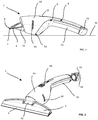
- the suction device 2 is shown in a side view.
- the suction device 2 is designed as a hand-operated window vacuum.
- the suction device 2 comprises in the front area a suction nozzle 4 designed as a flat nozzle with pulling lips 60 arranged above and below the flat nozzle opening, which is detachably arranged on a beak-shaped receptacle 62 formed from two parallel planes via a clamp connection.
- the suction device 2 has a suction and separation area adjoining the suction nozzle 4, a suction unit 10, a suction material container 8 and a closure 42.
- the aforementioned components are accommodated in a housing 6 of the suction device 2.
- the shape of the suction device 2 is initially bulged in the area of the separation area and of the suction unit 10 and then extends into a rear area which forms a handle 48.
- the handle 48 closes with the lock 42 at the distal end.
- the suction material container 8 is largely located in the handle 48 and extends to the end of the handle 48.
- an opening 40 is provided in the suction material container 8, which is sealed by the closure 42 against the escape of suction material, in particular water is.
- the housing 6 of the suction device 2 is constructed in several parts. It comprises an upper shell 64, which ventilation slots 66 for the exhaust air flow and a recess for a Has actuating button 68 for switching the device 2 on and off.
- the upper shell 64 of the housing 6 is placed on a lower part of the housing.
- As a handle shell 70 the lower part of the housing forms part of the handle 48, which is made in several parts.
- the handle shell 70 in turn simultaneously forms a lower boundary of the suction material container 8.
- the suction and separation areas are each received by a front part of the housing 6, which also forms the receptacle for the suction nozzle 62.
- the shape of the suction device 2 is designed in such a way that the device 2, when it is placed on a flat storage surface 72, is accommodated by two storage areas.
- the first storage area is formed by the lower part of the handle shell, on which two feet are provided as storage elements 74.
- the two storage elements 74 are arranged on both sides at a distance from a longitudinal axis of the suction device 2.
- a part of the lock 42 forms the second storage area.
- the two storage elements 74 allow the suction device 2 to be placed on the flat storage surface 72 in a stable manner.
- the storage areas are arranged on the suction device 2 in such a way that the suction nozzle 4 and in particular the pull-off lip 5 are spaced apart from the flat storage surface 72.
- Both the outer area of the closure 42 and the storage elements 74 designed as feet are made from a soft material, in particular from a rubber-like material. In this way, in addition to a stable and surface-friendly state of the device 2 when the device 2 is switched off, damage when using the device 2, if the device 2 does not come into contact with the surface to be cleaned or the surfaces around it, is avoided.
- FIG. 4 shows a perspective view of the suction device 2 from FIG Figure 1 .
- the upper part of the receptacle of the suction nozzle 62 can be seen, in which the suction nozzle 4, which is designed as a flat nozzle, is detachably inserted via the clamp connection. Due to the releasable connection, other suction nozzles can also be used in the intake of the suction nozzle, depending on the area of application.
- the closure 42 continuing the outer contour of the device 2 is shown spaced apart from the suction device 2 in the dismantled state.
- the closure 42 has at the end a gripping area which is formed by a raised edge in the rear area.
- FIG. 3 A larger representation of an embodiment of the closure 42 according to the invention is shown Figure 3 .
- the closure 42 is composed of a first closure element 44 and a second closure element 46.
- the first closure element 44 has the shape of a cylinder open on one side.
- the cylinder is chamfered at the open end.
- two sealing elements 58 designed as sealing rings are provided on the outside of the cylinder behind the chamfer, which sealing elements 58 are formed in one piece in the first closure element 44.
- the first closure element 44 is pushed into the opening of the suction material container 8 and seals the suction material container 8 against leakage of suction material.
- the first closure element 44 is formed from a rubber-like soft material.
- the closure element 44 can, however, also be formed from a plastic, onto which the sealing elements 58 are molded or placed as separate sealing rings.
- the first closure element 44 Since the task of the first closure element 44 is to seal the opening 40 of the suction material container 8 against the exit of the suction material, the first closure element 44 is correspondingly geometrically adapted to the opening 40 of the suction material container 8. In contrast, any desired shape can be selected for the second closure element 46.
- the second closure element 46 is arranged like a bell around the first closure element 44 and has a shape different from the first closure element 44.
- the geometry of the second closure element 46 is such that the outer contour of the suction device 2 is continued and the closure 42 forms the distal end of the suction device 2.
- the second closure element 46 is arranged at a distance from the first closure element 44 so that the first closure element 44 can be inserted into the opening of the suction material container 40.
- a wall 41 forming the opening of the suction material container 40 is then received between the first and second closure parts 44, 46 when the closure 42 is installed. Furthermore, the spacing also provides protection against impacts for the device 2 and protection of the seal produced by the first closure element 44.
- the closure 42 has a plurality of functional elements designed as ribs 50 and guide or centering elements 52 between the two closure elements 44, 46.
- the functional elements are each arranged on the second closure element 46 and connected to it in one piece.
- On the upper wall of the second closure element 46 two each are spaced apart symmetrically from the longitudinal axis of the device 2 Ribs 50 arranged in pairs are provided which are each shaped in such a way that they support the upper part of the second closure element 46 against the wall of the opening of the suction material container 41 when the closure 42 is installed, in particular rest against the wall of the opening of the suction material container 41.
- guide or centering elements 52 are provided symmetrically spaced apart from the longitudinal axis of the device 2.
- guide means 56 are provided on the outer wall of the opening of the suction material container 41.
- the corresponding guide or centering elements 52 and guide means 56 are preferably set up in such a way that the closure 42 is prevented from rotating relative to the housing 6 of the suction device 2.
- the guide or centering elements 52 can also serve as ribs for supporting the second closure element 46 against the wall of the opening of the suction material container 41.
- the functional means 56 are supported against the second closure element 46 on the side of the wall 41 of the opening of the suction material container 40.
- the functional elements preferably extend as far as the rear wall of the second closure element 46.
- Figure 4 shows the shutter 42 from Figure 3 in a front view.
- the significantly different shape of the sealing first closure element 44 from the second closure element 46 as well as the spacing of the closure elements 44, 46 from one another such that the wall of the opening of the suction material container 41 can be accommodated between them can be clearly seen.
- the ribs 50 which are arranged in pairs, and the guiding or centering elements 52 are adapted inwardly according to the round cross section of the wall of the opening of the suction material container 41.
- the guide or centering elements 52 are geometrically wider than the ribs 50. The width is designed in particular in such a way that the guide or centering elements 52 have sufficient rigidity and the closure 42 is secured against twisting.
- the guide or centering elements 52 corresponding to the guide means 56 on the wall of the opening of the suction material container 41, can also be designed in such a way that a type of bayonet lock or screw lock is implemented.
- FIG Figure 5 A sectional view of the previously described embodiment of the closure 42 is shown in FIG Figure 5 .
- the closure 42 is formed in one piece.
- the first and second closure elements 44, 46 have a common wall on the side facing away from the opening 40.
- the common wall has a convex shape, which forms a harmonious finish that matches the design line of the suction device.
- the previously described parking area of the closure 42 is also achieved via the convex geometry.
- the upper area of the rear wall of the second closure element 46 is thickened in the shape of a bead such that the gripping area of the closure 42 is not deformed when it is released from the suction device 2 and the closure 42 can be easily removed from the suction device 2.
- the sealing elements 58 which are integrally connected to it and designed as sealing rings, as well as the chamfer in the part of the cylinder facing the opening 40 can be seen.
- the sealing elements 58 can alternatively also be placed on or injection-molded onto the inner closure element 44.
- one of the ribs 50 can be seen, which extends continuously up to the rear wall of the second closure element 46.
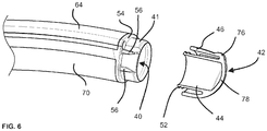
- FIG. 6 The detail of the rear area of the suction device 2 with the closure 42 removed is illustrated Figure 6 .
- the upper housing shell 64 is placed on the lower handle shell 70 and screwed to it.
- the wall of the opening of the suction material container 41 forms a cylindrical jacket and provides the functional means 56 which have already been described and which correspond to the guide or centering elements 52.
- the arrangement of the first closure element 44 in relation to the second closure element 46 is designed in such a way that the wall of the opening of the suction material container 41 is received by the closure 42 when the closure 42 is installed and the end face of the second closure element 46 abuts the flange 54.
- the described embodiments provide for the opening of the suction material container 40 to be internally sealed by the first closure element 44.
- Alternative designs can also be implemented according to the invention, for example that the first closure element 44 is slipped over the opening of the suction material container 40. In this case, the spacing then offers the corresponding impact protection to avoid leaks.
Landscapes
- Closures For Containers (AREA)
Abstract
Description
- Die Erfindung betrifft ein tragbares Sauggerät nach dem Oberbegriff des Anspruchs 1. Insbesondere betrifft die Erfindung ein tragbares Sauggerät mit einem in eine Saugdüse mündenden Saugkanal und mit einem Gehäuse, einem Sauggutbehälter mit einer Öffnung und einem die Öffnung verschließenden Verschluss und einem Saugaggregat zur Erzeugung einer Saugströmung, die einen an der Saugdüse anliegenden Saugunterdruck bereitstellt, und mit einer Abscheideeinrichtung, die die über die Saugdüse angesaugte Saugströmung in eine aus dem Sauggerät strömende Abluftströmung und in Sauggut in Form von Partikeln und/oder Fluidbestandteilen aufzuteilen vermag, wobei die abgeschiedenen Partikel oder Fluidbestandteile in dem Sauggutbehälter gesammelt sind. Zudem sind diese Geräte üblicherweise batteriebetrieben und werden in der Hand eines Benutzers gehalten, während dieser die Abziehlippe entlang der abzusaugenden Fläche führt.
- Tragbare Geräte dieser Art sind unter anderem aus der
EP 2 845 530 B1 bekannt. Die bekannten Sauggeräte werden verwendet, um ein Flüssigkeit-/Luftgemisch aufzusaugen. Dies kann, wie im Fall der genannten Vorrichtung, zum Aufsaugen von Flüssigkeit, zum Beispiel von einer ebenen Oberfläche wie einer Tischplatte, von Fensterscheiben oder Fliesen erfolgen. Zum rückständefreien Reinigen der Oberflächen sehen ist bei den gattungsgemäßen Geräten eine an der Saugdüse angeordnete Abziehlippe vorgesehen. - Die gattungsgemäßen Geräte haben oftmals am Sauggutbehälter einen als kleinen Stopfen ausgeführten Verschluss zur Entleerung des Sauggut sowie einer größeren Öffnung, bzw. Teilung des Sauggutbehälters für eine bessere Reinigung. Auch ist die größere Öffnung bzw. Teilung des Sauggutbehälters aus Gründen der Montierbarkeit vorgesehen, um die Montage von innen liegenden Teilen wie beispielsweise der Sauggutführung zu ermöglichen.
- Bei den gattungsgemäßen Geräten ist das Entleeren des Sauggutbehälters aufwendig und langwierig und damit nicht anwendungsfreundlich. Oftmals müssen einige Bauteile des Sauggeräts zunächst demontiert werden und je nach Sauggerät auch Verbindungselemente gelöst werden, um den Sauggutbehälter zu entleeren und zu reinigen. Bei der Entleerung über einen als Stopfen ausgeführten Verschluss ist ein restloses Entleeren häufig nicht möglich, da oftmals geringe Sauggutmengen in durch die Sauggutbehältergeometrie gebildeten Saugguttaschen überbleiben.
- Um die Dichtigkeit des Verschlusses sicherzustellen, ist es üblicherweise erforderlich die Verschlüsse der gattungsgemäßen Sauggeräte mit einer runden Geometrie und Dichtkontur auszugestalten. Hieraus resultieren gestalterische Einschränkungen in Bezug auf die Lage und Ausgestaltung des Verschlusses und damit auf das Design des Sauggeräts.
- Es ist daher die Aufgabe der Erfindung, ein Sauggerät bereitzustellen, das bei niedrigen Herstellungskosten und flexibler Geometriegebung ein einfaches Entleeren des Sauggutbehälters ermöglicht.
- Die Lösung der Aufgabe erfolgt erfindungsgemäß durch ein tragbares Sauggerät mit den Merkmalen des Anspruchs 1. Bevorzugte Ausgestaltungen der Erfindung sind in den Unteransprüchen und der nachfolgenden Beschreibung angegeben, die jeweils einzeln oder in Kombination einen Aspekt der Erfindung darstellen können.
- Erfindungsgemäß ist bei dem Sauggerät der Verschluss aus zumindest einem ersten Verschlusselement und einem zweiten Verschlusselement gebildet, derart, dass das erste Verschlusselement dazu eingerichtet ist, die Öffnung des Sauggutbehälters gegen Austritt von Sauggut abzudichten und das zweite Verschlusselement außerhalb des ersten Verschlusselements angeordnet ist.
- Die zweielementige Ausgestaltung des Stopfens ermöglicht funktionelle Vorteile bei gleichzeitiger hoher Gestaltungsfreiheit. So kann beispielsweise eine sichere Abdichtung durch eine runde Kontur einer dichtenden Fläche des ersten Verschlusselements realisiert sein, aber das äußere zweite Verschlusselement eingerichtet sein, eine Außenkontur des Gehäuses des Sauggeräts, also die Sauggerätegeometrie fortzuführen.
- Durch die erfindungsgemäße Ausgestaltung kann der Verschluss konstruktiv derart gestaltet werden, dass ein übermäßiger Materialeinsatz sowie Masseanhäufungen vermieden werden. Dies wirkt sich wiederum positiv auf die Kosten aus. Auch können fertigungsbedingte Einfallstellen vermieden werden.
- Bevorzugt ist der Verschluss, also das erste und zweite Verschlusselement, einstückig ausgebildet. Insbesondere ist das zweite Verschlusselement von dem ersten Verschlusselement beabstandet. Dabei kann das zweite Verschlusselement glockenartig um das erste Verschlusselement angeordnet sein.
- Ein Vorteil hiervon ist, dass die auf die Außenwandung des zweiten Verschlusselements wirkenden Kräfte von dem inneren, dichtenden ersten Verschlusselement entkoppelt werden, sodass eine unerwünschte Undichtigkeit, die zum Austritt von Sauggut aus dem Sauggutbehälter führen kann, vermieden wird.
- Bei den erfindungsgemäßen Sauggeräten weist die Öffnung des Sauggutbehälters in vorteilhafterweise einen runden Querschnitt auf. Das erste Verschlusselement bildet dann einen die Öffnung abdichtenden korrespondierenden runden Querschnitt aus. Das zweite Verschlusselement ist eingerichtet, die Außenkontur des Gehäuses des Sauggeräts fortzuführen. Insbesondere kann das zweite Verschlusselement des Verschlusses eine dreidimensionale, einen Teil der Außenkontur bestimmenden Abschnitt ausbilden, z.B. ein kappenförmiges Element.
- Die Form des Sauggeräts ist in einer besonders vorteilhaften Ausgestaltung der Erfindung so ausgebildet, dass sich das Sauggerät auf dem der Saugdüse gegenüberliegenden Endabschnitt in einen Griff des Sauggeräts erstreckt.
- In einer bevorzugten Ausführungsform ist zumindest ein Teil des Sauggutbehälters im Griff und der Verschluss im Griff angeordnet. Da das zweite Verschlusselement unabhängig vom ersten Verschlusselement gestaltet werden kann, bildet der Verschluss in vorteilhafter Weise einen Teil des Griffs.
- Eine besonders kompakte Bauweise des Sauggeräts wird dadurch erreicht, dass sich der Sauggutbehälter bis zum distalen Ende des Griffs erstreckt. Auf diese Weise wird auch hier der Bauraum vollständig ausgenutzt. Der Verschluss kann dabei am distalen Ende des Griffs angeordnet sein und in besonders vorteilhafter Weise direkt das distale Ende des Griffs bilden. So kann auf diese Weise nicht nur eine durch den Verschluss verschließbare größere Öffnung im Sauggutbehälter vorgesehen sein, die wiederum ein Entleeren des Sauggutbehälters erleichtert, sondern es wird auch durch die Anordnung des Verschlusses am distalen Ende des Griffs oder auch beim Ausbilden des Sauggutbehälters bis zum distalen Endes des Griffs ein restloses Entleeren des Sauggutbehälters ermöglicht.
- Das zweite Verschlusselement ist bevorzugt aus einem Weichmaterial gebildet. Dies kann beispielsweise ein weicher Kunststoff oder ein gummielastisches Material sein. Auf diese Weise wird eine gute Haptik erreicht, sodass der Benutzer den Verschluss leicht ergreifen und öffnen kann. Zudem stellt der Verschluss auch einen Stoß- und Kratzschutz dar, wenn das Gerät bei der Benutzung versehentlich gegen ein Objekt oder Gegenstand stößt bzw. die zu reinigende Fläche beim Reinigungsvorgang berührt wird oder das Sauggerät gar hinunterfällt.
- Ferner kann der Verschluss ein oder mehrere Funktionselemente aufweisen, die mit im Bereich der Öffnung des Sauggutbehälters korrespondierenden Gegenstücken zusammenwirken. Die Funktionselemente können dabei vorzugsweise zwischen dem ersten Verschlusselement und dem zweiten Verschlusselement angeordnet sein.
- Beispielsweise kann ein Teil der Funktionselemente als Rippen ausgebildet sein. Diese sind eingerichtet das zweite Verschlusselement gegenüber dem ersten Verschlusselement abzustützen.
- Alternativ oder ergänzend kann auch zumindest ein Teil der Funktionselemente als Verbindungselemente, insbesondere in Verbindung mit korrespondierenden Gegenstücken im Bereich der Öffnung des Sauggutbehälters ausgebildet sein. Z.B. können dies Schraub- oder Bajonettverschluss-Verbindungselemente sein.
- Das erste Verschlusselement ist bevorzugt aus einem Weichmaterial ausgebildet und so ausgestaltet, die Öffnung des Sauggutbehälters dichtend gegenüber der Umgebung zu verschließen. Auch kann alternativ oder zusätzlich ein separates Dichtelement am ersten Verschlusselement angeordnet sein, um die Abdichtung der Öffnung zu erreichen. Das Dichtelement kann als separates Teil ausgebildet sein oder aber auch am ersten Verschlusselement angespritzt sein.
- Ein weiterer Vorteil ist, dass die auf die Außenwandung wirkenden Kräfte von der inneren, dichteren Wandung entkoppelt werden, sodass eine unerwünschte Undichtigkeit vermieden werden kann.
- Weitere Merkmale und Vorteile der Erfindung ergeben sich aus der nachfolgenden Beschreibung bevorzugter Ausführungsbeispiele anhand der Zeichnungen.
- In den Zeichnungen zeigt:
- Fig. 1
- eine Seitenansicht des erfindungsgemäßen Sauggeräts in einer ersten Ausführungsform,
- Fig. 2
- eine perspektivische Ansicht des erfindungsgemäßen Sauggeräts aus
Fig. 1 mit abgezogenem Verschluss, - Fig. 3
- eine Ausführungsform eines Stopfens für das Sauggerät aus
Fig. 1 , - Fig. 4
- eine Vorderansicht des Stopfens aus
Fig. 3 ., - Fig. 5
- eine perspektivische Ansicht des Verschlusses aus
Fig. 3 im Schnitt, - Fig. 6
- den hinteren Teil einer unteren Griffschale des Sauggeräts in perspektivischer Ansicht und des zugehörigen Verschlusses,
- In
Figur 1 ist das Sauggerät 2 in einer Seitenansicht dargestellt. Das Sauggerät 2 ist als ein handbetätigter Fenstersauger ausgebildet. Das Sauggerät 2 umfasst im vorderen Bereich eine als Flachdüse ausgeführte Saugdüse 4 mit oberhalb und unterhalb der Flachdüsenöffnung angeordneten Abziehlippen 60, die an einer sich aus zwei parallelen Ebenen bildenden schnabelförmigen Aufnahme 62 über eine Klemmverbindung lösbar angeordnet ist. In Strömungsrichtung weisend weist das Sauggerät 2 einen sich an die Saugdüse 4 anschließenden Ansaug- und Abscheidebereich, ein Saugaggregat 10, einen Sauggutbehälter 8 und einen Verschluss 42 auf. Die zuvor genannten Komponenten sind von einem Gehäuse 6 des Sauggeräts 2 aufgenommen. - Hinter der schnabelförmigen Aufnahme 62 ist die Form des Sauggeräts 2 zunächst im Bereich des Abscheidebereichs und des Saugaggregats 10 bauchig geformt und erstreckt sich anschließend in einen hinteren Bereich, der einen Handgriff 48 bildet. Der Handgriff 48 schließt am distalen Ende mit dem Verschluss 42 ab. Der Sauggutbehälter 8 befindet sich größtenteils in dem Handgriff 48 und erstreckt sich bis zum Ende des Handgriffs 48. Am distalen Ende des Handgriffs 48 ist eine Öffnung 40 im Sauggutbehälter 8 vorgesehen, die durch den Verschluss 42 gegen Austritt von Sauggut, insbesondere Wasser, dichtend verschlossen ist.
- Das Gehäuse 6 des Sauggeräts 2 ist mehrteilig ausgebildet. Es umfasst eine obere Schale 64, welche Lüftungsschlitze 66 für die Abluftströmung und eine Aussparung für einen Betätigungsknopf 68 zum An- und Ausschalten des Geräts 2 aufweist. Die obere Schale 64 des Gehäuses 6 ist auf einen unteren Teil des Gehäuses aufgesetzt. Der untere Teil des Gehäuses bildet als eine Griffschale 70 einen Teil des Handgriffs 48, der mehrteilig ausgeführt ist. Die Griffschale 70 wiederum bildet gleichzeitig eine untere Begrenzung des Sauggutbehälters 8. Ansaug- und Abscheidebereich sind jeweils von einem vorderen Teil des Gehäuses 6, der zudem die Aufnahme für die Saugdüse 62 ausbildet, aufgenommen.
- Die Form des Sauggerätes 2 ist derart ausgebildet, dass sich das Gerät 2 bei dessen Abstellen auf eine ebene Abstellfläche 72 von zwei Abstellbereichen aufgenommen ist. Den ersten Abstellbereich bildet der untere Teil der Griffschale, an dem zwei Füße als Abstellelemente 74 vorgesehen sind. Die zwei Abstellelemente 74 sind beidseitig von einer Längsachse des Sauggeräts 2 beabstandet angeordnet. Den zweiten Abstellbereich bildet ein Teil des Verschlusses 42. Durch die beiden Abstellelemente 74 kann das Sauggerät 2 kippstabil auf die ebene Abstellfläche 72 hingestellt werden.
- Die Abstellbereiche sind so am Sauggerät 2 angeordnet, dass die Saugdüse 4 und insbesondere die Abziehlippe 5 von der ebenen Abstellfläche 72 beabstandet ist. Sowohl der Außenbereich des Verschlusses 42 als auch die als Füße ausgebildeten Abstellelemente 74 sind aus einem Weichmaterial, insbesondere aus einem gummiartigen Material gebildet. Hierdurch wird neben einem stabilen und oberflächenschonenden Stand des Geräts 2 beim Abstellen des Geräts 2 auch eine Beschädigung bei der Benutzung des Geräts 2, bei nicht bestimmungsgemäßer Berührung des Geräts 2 mit der zu reinigenden Oberfläche oder den darum liegenden Oberflächen vermieden.
-
Figur 2 zeigt eine perspektivische Ansicht des Sauggeräts 2 ausFigur 1 . Zu erkennen ist der obere Teil der Aufnahme der Saugdüse 62, in der die als Flachdüse ausgebildete Saugdüse 4 lösbar über die Klemmverbindung eingesetzt ist. Durch die lösbare Verbindung können, je nach Anwendungsbereich, auch andere Saugdüsen in die Aufnahme der Saugdüse eingesetzt werden. Der die Außenkontur des Geräts 2 fortführende Verschluss 42 ist im demontierten Zustand beabstandet vom Sauggerät 2 dargestellt. Der Verschluss 42 weist am Ende einen Greifbereich auf, der durch einen erhöhten Rand im hinteren Bereich gebildet ist. - Eine größere Darstellung einer Ausführungsform des erfindungsgemäßen Verschlusses 42 zeigt
Figur 3 . Der Verschluss 42 setzt sich aus einem ersten Verschlusselement 44 und einem zweiten Verschlusselement 46 zusammen. Das erste Verschlusselement 44 hat die Form eines einseitig offenen Zylinders. Der Zylinder ist am offenen Ende abgefast. Ferner sind auf der Außenseite des Zylinders hinter der Abfasung zwei als Dichtringe ausgebildete Dichtelemente 58 vorgesehen, die einstückig in dem ersten Verschlusselement 44 ausgebildet sind. - Das erste Verschlusselement 44 wird in die Öffnung des Sauggutbehälters 8 geschoben und dichtet den Sauggutbehälter 8 gegen Austritt von Sauggut ab. In der Ausführungsform ist das erste Verschlusselement 44 aus einem gummiartigen Weichmaterial gebildet. Das Verschlusselement 44 kann aber auch aus einem Kunststoff gebildet sein, an den die Dichtelemente 58 angespritzt oder als separate Dichtringe aufgesetzt werden.
- Da die Aufgabe des ersten Verschlusselement 44 ist, die Öffnung 40 des Sauggutbehälters 8 gegen den Austritt des Saugguts dichtend zu verschließen, ist das erste Verschlusselement 44 entsprechend korrespondierend an die Öffnung 40 des Sauggutbehälters 8 geometrisch angepasst. Dagegen kann für das zweite Verschlusselement 46 eine beliebige Form gewählt werden.
- Das zweite Verschlusselement 46 ist glockenartig um das erste Verschlusselement 44 angeordnet und weist eine vom ersten Verschlusselement 44 verschiedene Form auf.
- Vorliegend ist das zweite Verschlusselement 46 von seiner Geometrie so ausgebildet, dass die Außenkontur des Saugeräts 2 weitergeführt ist und der Verschluss 42 das distale Ende des Sauggeräts 2 bildet.
- Das zweite Verschlusselement 46 ist vom ersten Verschlusselement 44 beanstandet angeordnet, damit das erste Verschlusselement 44 in die Öffnung des Sauggutbehälters 40 eingesetzt werden kann. Eine die Öffnung des Sauggutbehälters 40 bildende Wandung 41 ist dann bei montiertem Verschluss 42 zwischen dem ersten und zweiten Verschlussteil 44, 46 aufgenommen. Ferner bewirkt die Beabstandung auch einen Stoßschutz des Geräts 2 und einen Schutz der durch das erste Verschlusselement 44 bewirkten Dichtung.
- Der Verschluss 42 weist zwischen den beiden Verschlusselementen 44, 46 mehrere als Rippen 50 und Führungs- bzw. Zentrierelemente 52 ausgebildete Funktionselemente auf. Die Funktionselemente sind jeweils am zweiten Verschlusselement 46 angeordnet und mit diesem einstückig verbunden. An der oberen Wandung des zweiten Verschlusselementes 46 sind symmetrisch von der Längsachse des Gerätes 2 beanstandet jeweils zwei paarweise angeordnete Rippen 50 vorgesehen, die jeweils derart geformt sind, dass sie bei montiertem Verschluss 42 den oberen Teil des zweiten Verschlusselementes 46 gegen die Wandung der Öffnung des Sauggutbehälters 41 abstützen, insbesondere an der Wandung der Öffnung des Sauggutbehälters 41 anliegen.
- Ferner sind von der Längsachse des Geräts 2 symmetrisch beanstandete, als Führungs- bzw. Zentrierelemente 52 ausgebildete Funktionselemente vorgesehen. Auf der äußeren Wandung der Öffnung des Sauggutbehälters 41 sind zu den Führung- bzw. Zentrierelementen 52 korrespondierende Führungsmittel 56 vorgesehen.
- Hierdurch wird ermöglicht, dass der Verschluss 42 nur in der bestimmungsgemäß vorgesehenen Ausrichtung auf die Öffnung des Sauggutbehälters 40 gesetzt werden kann, damit insbesondere die Außenkontur des Sauggeräts 2 fortgeführt werden kann. Ferner sind die korrespondierenden Führung- bzw. Zentrierelemente 52 und Führungsmittel 56 bevorzugt derart eingerichtet, dass der Verschluss 42 gegen ein Verdrehen relativ zum Gehäuse 6 des Sauggeräts 2 verhindert ist. Gleichzeitig können die Führungs- bzw. Zentrierelemente 52 auch als Rippen zum Abstützen des zweiten Verschlusselement 46 gegenüber der Wandung der Öffnung des Sauggutbehälters 41 dienen. Auch kann alternativ vorgesehen sein, dass sich die Funktionsmittel 56 auf Seiten der Wandung 41 der Öffnung des Sauggutbehälters 40 gegen das zweite Verschlusselement 46 abstützen. Bevorzugt erstrecken sich die Funktionselemente aus Stabilitätsgründen bis zur hinteren Wandung des zweiten Verschlusselementes 46.
-
Figur 4 zeigt den Verschluss 42 ausFigur 3 in einer Vorderansicht. Gut zu erkennen ist die wesentlich verschiedene Formgebung des dichtenden ersten Verschlusselements 44 vom zweiten Verschlusselement 46 sowie die Beabstandung der Verschlusselemente 44, 46 voneinander derart, dass die Wandung der Öffnung des Sauggutbehälters 41 zwischen diesen aufgenommen werden kann. Aus Gründen der zuvor genannten Abstütz- oder Führungsfunktionen sind die jeweils paarweise angeordneten Rippen 50 und die Führung- bzw. Zentrierelemente 52 nach innen hin entsprechend des runden Querschnitts der Wandung der Öffnung des Sauggutbehälters 41 angepasst. Die Führung- bzw. Zentrierelemente 52 sind geometrisch breiter ausgeführt, als die Rippen 50. Die Breite ist insbesondere derart ausgelegt, dass die Führungs- bzw. Zentrierelemente 52 eine ausreichende Steifigkeit aufweisen und der Verschluss 42 gegen Verdrehen gesichert ist. - Auch können die Führungs- bzw. Zentrierelemente 52 korrespondierend mit den Führungsmitteln 56 auf der Wandung der Öffnung des Sauggutbehälters 41 so ausgebildet sein, dass eine Art Bajonett-Verschluss oder Schraubverschluss realisiert ist.
- Eine Schnittansicht der zuvor beschriebenen Ausführungsform des Verschlusses 42 zeigt die
Figur 5 . Der Verschluss 42 ist einstückig ausgebildet. Das erste und zweite Verschlusselement 44, 46 haben eine gemeinsame Wandung auf der von der Öffnung 40 abgewandten Seite. Die gemeinsame Wandung hat eine konvexe Form, welche einen harmonischen, zur Designlinie des Sauggeräts passenden Abschluss bildet. Auch wird über die konvexe Geometrie der zuvor beschriebene Abstellbereich des Verschlusses 42 erreicht. - Der obere Bereich der hinteren Wandung des zweiten Verschlusselementes 46 ist wulstförmig verdickt ausgebildet, derart, dass sich der Greifbereich des Verschlusses 42 beim Lösen vom Sauggerät 2 nicht verformt und ein problemloses Abziehen des Verschlusses 42 vom Sauggerät 2 möglich ist.
- Beim ersten Verschlusselement 44 sind die einstückig mit diesem verbundenen, als Dichtringe ausgeführten Dichtelemente 58 sowie die Abfasung im der Öffnung 40 zugewandten Teil des Zylinders zu erkennen. Die Dichtelemente 58 können je nach Material alternativ auch auf das innere Verschlusselement 44 aufgesetzt oder angespritzt werden. Ferner ist eine der Rippen 50 zu erkennen, die sich bis zur hinteren Wandung des zweiten Verschlusselementes 46 durchgängig erstreckt.
- Den Ausschnitt des hinteren Bereichs des Sauggeräts 2 mit abgezogenem Verschluss 42 illustriert
Figur 6 . Auf die untere Griffschale 70 ist die obere Gehäuseschale 64 aufgesetzt und mit dieser verschraubt. Die Wandung der Öffnung des Sauggutbehälters 41 bildet einen zylinderförmigen Mantel aus und sieht die bereits beschriebenen korrespondierend zu den Führung- bzw. Zentrierelementen 52 ausgebildeten Funktionsmittel 56 vor. Auf der der Öffnung abgewandten Seite befindet sich ein Flansch 54, der von seinen Außengeometrie der Außenkontur des Sauggeräts 2 folgt. In dem Flansch 54 sind Durchbrüche für das Verschrauben der oberen Gehäuseschale 64 vorgesehen. Die Anordnung des ersten Verschlusselements 44 zum zweiten Verschlusselement 46 ist derart ausgestaltet, dass die Wandung der Öffnung des Sauggutbehälters 41 bei Montage des Verschlusses 42 von dem Verschluss 42 aufgenommen ist und die Stirnseite des zweiten Verschlusselements 46 gegen den Flansch 54 stößt. - Die beschriebenen Ausführungsformen sehen ein inneres Abdichten der Öffnung des Sauggutbehälters 40 durch das erste Verschlusselement 44 vor. Alternative Gestaltungen sind ebenfalls erfindungsgemäß umsetzbar, beispielsweise dass das erste Verschlusselement 44 über die Öffnung des Sauggutbehälters 40 gestülpt ist. Die Beabstandung bietet in diesem Fall dann den entsprechenden Stoßschutz zur Vermeidung von Undichtigkeiten.
-
- 2
- Sauggerät
- 4
- Saugdüse
- 5
- Abziehlippen
- 6
- Gehäuse
- 8
- Sauggutbehälter
- 10
- Saugaggregat
- 12
- Abscheideeinrichtung
- 40
- Öffnung des Sauggutbehälters
- 41
- Wandung der Öffnung des Sauggutbehälters
- 42
- Verschluss
- 44
- erstes Verschlusselement
- 46
- zweites Verschlusselement
- 48
- Handgriff
- 50
- Rippen
- 52
- Führungs- bzw. Zentrierelemente
- 54
- Flansch
- 56
- Führungsmittel
- 58
- Dichtelemente
- 60
- Abziehlippe
- 62
- Aufnahme für Saugdüse
- 64
- obere Gehäuseschale
- 66
- Lüftungsschlitze
- 68
- Betätigungsknopf
- 70
- Griffschale
- 72
- Abstellfläche
- 74
- Abstellelemente
- 76
- Haltewulst des Verschlusses
- 78
- gemeinsame Wandung
Claims (15)
- Tragbares Sauggerät (2) mit einem in eine Saugdüse (4) mündenden Saugkanal und mit einem Gehäuse (6), einem Sauggutbehälter (8) mit einer Öffnung (40) und einem die Öffnung (40) verschließenden Verschluss (42), und einem Saugaggregat (10) zur Erzeugung einer Saugströmung, die einen an der Saugdüse (4) anliegenden Saugunterdruck bereitstellt, mit einer Abscheideeinrichtung (12), die die über die Saugdüse angesaugte Saugströmung in eine aus dem Sauggerät (2) strömende Abluftströmung und in Sauggut in Form von Partikeln und/oder Fluidbestandteilen aufzuteilen vermag, wobei die abgeschiedenen Partikel oder Fluidbestandteile in dem Sauggutbehälter (8) gesammelt sind und durch Öffnen des Verschlusses (42) des Sauggutbehälters (8) entleert werden kann, dadurch gekennzeichnet, dass der Verschluss (42) aus zumindest einem ersten Verschlusselement (44) und einem zweiten Verschlusselement (46) gebildet ist, derart, dass das erste Verschlusselement (44) dazu eingerichtet ist, die Öffnung (40) des Sauggutbehälters (8) gegen Austritt von Sauggut abzudichten und das zweite Verschlusselement (46) außerhalb des ersten Verschlusselements (44) angeordnet ist.
- Tragbares Sauggerät (2) nach Anspruch 1, dadurch gekennzeichnet, dass der Verschluss (42) einstückig ausgebildet ist.
- Tragbares Sauggerät (2) nach einem der vorstehenden Ansprüche, dadurch gekennzeichnet, dass das zweite Verschlusselement (46) glockenartig um das erste Verschlusselement (44) angeordnet ist.
- Tragbares Sauggerät (2) nach einem der vorstehenden Ansprüche, dadurch gekennzeichnet, dass das zweite Verschlusselement (46) von dem ersten Verschlusselement (44) beabstandet ist.
- Tragbares Sauggerät (2) nach einem der vorstehenden Ansprüche, dadurch gekennzeichnet, dass die Öffnung des Sauggutbehälters (40) einen runden Querschnitt aufweist und das erste Verschlusselement (44) einen zur Öffnung (40) korrespondierenden runden Querschnitt aufweist.
- Tragbares Sauggerät (2) nach einem der vorstehenden Ansprüche, dadurch gekennzeichnet, dass das zweite Verschlusselement (46) eingerichtet ist, eine Außenkontur des Gehäuses (6) des Sauggeräts (2) fortzuführen.
- Tragbares Sauggerät (2) nach einem der vorstehenden Ansprüche, dadurch gekennzeichnet, dass das zweite Verschlusselement (46) des Verschlusses (42) eine dreidimensionale, einen Teil der Außenkontur bestimmenden Abschnitt ausbildet, insbesondere ein kappenförmiges Element.
- Tragbares Sauggerät (2) nach einem der vorstehenden Ansprüche, dadurch gekennzeichnet, dass zumindest ein Teil des Sauggutbehälters im Griff (48) und der Verschluss (42) im Griff (48) angeordnet ist, insbesondere einen Teil des Griffs (48) bildet.
- Tragbares Sauggerät (2) nach dem vorstehenden Anspruch, dadurch gekennzeichnet, dass sich der Sauggutbehälter (8) bis zum distalen Ende des Griffs (48) erstreckt und der Verschluss (42) am distalen Ende des Griffs (48) angeordnet ist, insbesondere das distale Ende des Griffs (48) bildet.
- Tragbares Sauggerät (2) nach einem der vorstehenden Ansprüche, dadurch gekennzeichnet, dass der Verschluss (42) ein oder mehrere Funktionselemente, die mit im Bereich der Öffnung des Sauggutbehälters (40) korrespondierenden Gegenstücken zusammenwirken, aufweist, wobei die Funktionselemente insbesondere zwischen dem ersten Verschlusselement (44) und dem zweiten Verschlusselement (46) angeordnet sind.
- Tragbares Sauggerät (2) nach einem der vorstehenden Ansprüche, dadurch gekennzeichnet, dass zumindest ein Teil der Funktionselemente als Rippen (50) ausgebildet sind, wobei die Rippen (50) derart eingerichtet sind, das zweite Verschlusselement (46) gegenüber dem ersten Verschlusselement (44) und/oder einer Wandung der Öffnung des Sauggutbehälters (41) abzustützen.
- Tragbares Sauggerät (2) nach einem der beiden vorstehenden Ansprüche, dadurch gekennzeichnet, dass zumindest ein Teil der Funktionselemente als Verbindungselemente, insbesondere in Verbindung mit den korrespondierenden Gegenstücken im Bereich der Öffnung als Schraub- oder Bajonett-Verbindungselemente ausgebildet sind.
- Tragbares Sauggerät (2) nach dem vorstehenden Anspruch, dadurch gekennzeichnet, dass ein Dichtelement (58) am ersten Verschlusselement (44) angeordnet ist, um die Öffnung (40) des Sauggutbehälters (8) gegen Austritt von Sauggut abzudichten, wobei das Dichtelement (58) insbesondere an das erste Verschlusselement (44) angespritzt ist.
- Tragbares Sauggerät (2) nach einem der vorstehenden Ansprüche, dadurch gekennzeichnet, dass zumindest das zweite Verschlusselement (46) aus einem Weichmaterial gebildet ist, insbesondere aus einem gummielastischen Material.
- Tragbares Sauggerät (2) nach einem der vorstehenden Ansprüche, dadurch gekennzeichnet, dass der Verschluss (42) im hinteren Bereich einen Haltewulst (76) aufweist.
Priority Applications (1)
| Application Number | Priority Date | Filing Date | Title |
|---|---|---|---|
| EP19186097.2A EP3763266B1 (de) | 2019-07-12 | 2019-07-12 | Tragbares sauggerät |
Applications Claiming Priority (1)
| Application Number | Priority Date | Filing Date | Title |
|---|---|---|---|
| EP19186097.2A EP3763266B1 (de) | 2019-07-12 | 2019-07-12 | Tragbares sauggerät |
Publications (2)
| Publication Number | Publication Date |
|---|---|
| EP3763266A1 true EP3763266A1 (de) | 2021-01-13 |
| EP3763266B1 EP3763266B1 (de) | 2021-09-01 |
Family
ID=67262202
Family Applications (1)
| Application Number | Title | Priority Date | Filing Date |
|---|---|---|---|
| EP19186097.2A Active EP3763266B1 (de) | 2019-07-12 | 2019-07-12 | Tragbares sauggerät |
Country Status (1)
| Country | Link |
|---|---|
| EP (1) | EP3763266B1 (de) |
Citations (7)
| Publication number | Priority date | Publication date | Assignee | Title |
|---|---|---|---|---|
| US6216314B1 (en) * | 1999-08-31 | 2001-04-17 | John N. Dangerfield | Device for removing accumulated grease from culinary utensils |
| US6347428B1 (en) * | 2000-01-12 | 2002-02-19 | Royal Appliance Mfg. Co. | Hand-held wet/dry vacuum |
| US6687952B1 (en) * | 2002-01-07 | 2004-02-10 | Hmi Industries, Inc. | Wet vacuum cleaner attachment for vacuum cleaners |
| GB2437702A (en) * | 2006-05-04 | 2007-11-07 | Richards Morphy N I Ltd | Attachment device for a vacuum cleaner |
| CN203898196U (zh) * | 2014-06-24 | 2014-10-29 | 东莞瓦利电器制品有限公司 | 手提式表面真空清洁机 |
| EP2837316A2 (de) * | 2013-08-13 | 2015-02-18 | Hoover Limited | Tragbarer Saugreiniger |
| EP2845530A1 (de) | 2013-09-05 | 2015-03-11 | Leifheit Ag | Tragbares Sauggerät für Flüssigkeiten oder Flüssigkeits-/Luftgemische |
Family Cites Families (4)
| Publication number | Priority date | Publication date | Assignee | Title |
|---|---|---|---|---|
| DE29622010U1 (de) * | 1996-12-18 | 1997-03-13 | Leifheit Ag, 56377 Nassau | Scheibenwischer |
| US6082595A (en) * | 1998-07-15 | 2000-07-04 | Lin; Chung Sing | Detergent dispenser with a window wiper |
| GB0907165D0 (en) * | 2009-04-27 | 2009-06-10 | Power John R | The ice breaker |
| ES2649139T3 (es) * | 2013-07-18 | 2018-01-10 | Alfred Kärcher Gmbh & Co. Kg | Aparato de limpieza de superficies duras portátil |
-
2019
- 2019-07-12 EP EP19186097.2A patent/EP3763266B1/de active Active
Patent Citations (7)
| Publication number | Priority date | Publication date | Assignee | Title |
|---|---|---|---|---|
| US6216314B1 (en) * | 1999-08-31 | 2001-04-17 | John N. Dangerfield | Device for removing accumulated grease from culinary utensils |
| US6347428B1 (en) * | 2000-01-12 | 2002-02-19 | Royal Appliance Mfg. Co. | Hand-held wet/dry vacuum |
| US6687952B1 (en) * | 2002-01-07 | 2004-02-10 | Hmi Industries, Inc. | Wet vacuum cleaner attachment for vacuum cleaners |
| GB2437702A (en) * | 2006-05-04 | 2007-11-07 | Richards Morphy N I Ltd | Attachment device for a vacuum cleaner |
| EP2837316A2 (de) * | 2013-08-13 | 2015-02-18 | Hoover Limited | Tragbarer Saugreiniger |
| EP2845530A1 (de) | 2013-09-05 | 2015-03-11 | Leifheit Ag | Tragbares Sauggerät für Flüssigkeiten oder Flüssigkeits-/Luftgemische |
| CN203898196U (zh) * | 2014-06-24 | 2014-10-29 | 东莞瓦利电器制品有限公司 | 手提式表面真空清洁机 |
Also Published As
| Publication number | Publication date |
|---|---|
| EP3763266B1 (de) | 2021-09-01 |
Similar Documents
| Publication | Publication Date | Title |
|---|---|---|
| EP2198970B2 (de) | Kartuschenkolben | |
| DE69808865T2 (de) | Selbstentlüftender Kolben | |
| DE202008014389U1 (de) | Fließbecher für eine Farbspritzpistole | |
| CH645687A5 (de) | Inspektionskammer, insbesondere fuer drainage-zwecke. | |
| DE202015001781U1 (de) | Zylinder-Kolben-Anordnung für ein Flaschenaufsatzgerät | |
| DE202014011488U1 (de) | Tragbares Sauggerät | |
| DE102018106184A1 (de) | Mischvorrichtung mit Dichtung | |
| EP3677159A1 (de) | Anordnung eines staubfilterbeutels in einem staubsauger | |
| DE102013021277A1 (de) | Tragbares Hartflächenabsauggerät | |
| CH685327A5 (de) | Anschlussvorrichtung zum Anschliessen eines Gebläses an ein Schutzmaskenfilter. | |
| DE102005041811A1 (de) | Staubsaugerbeutel mit Kunststoffflansch | |
| EP3763266B1 (de) | Tragbares sauggerät | |
| EP1099899A2 (de) | Schlauch | |
| EP4201282A2 (de) | Flächenreinigungsgerät | |
| EP3763267B1 (de) | Tragbares sauggerät | |
| EP3763264B1 (de) | Tragbares sauggerät | |
| EP3763263B1 (de) | Tragbares sauggerät | |
| EP0617655B1 (de) | Rasiervorrichtung, insbesondere einwegrasierer | |
| EP0796795A2 (de) | Einsatzstück zur Belüftung eines Behälters für Flüssigkeiten | |
| DE19816776C2 (de) | Milch-Absaugvorrichtung | |
| DE1984477U (de) | Verschlusskappe. | |
| DE202014011047U1 (de) | Saugdüse und Hartflächenabsauggerät | |
| EP3145830A1 (de) | Behälterverschluss | |
| EP2517974A1 (de) | Trinkflasche | |
| DE102019002290A1 (de) | Verschlusskappe |
Legal Events
| Date | Code | Title | Description |
|---|---|---|---|
| PUAI | Public reference made under article 153(3) epc to a published international application that has entered the european phase |
Free format text: ORIGINAL CODE: 0009012 |
|
| STAA | Information on the status of an ep patent application or granted ep patent |
Free format text: STATUS: EXAMINATION IS IN PROGRESS |
|
| 17P | Request for examination filed |
Effective date: 20200221 |
|
| AK | Designated contracting states |
Kind code of ref document: A1 Designated state(s): AL AT BE BG CH CY CZ DE DK EE ES FI FR GB GR HR HU IE IS IT LI LT LU LV MC MK MT NL NO PL PT RO RS SE SI SK SM TR |
|
| AX | Request for extension of the european patent |
Extension state: BA ME |
|
| GRAP | Despatch of communication of intention to grant a patent |
Free format text: ORIGINAL CODE: EPIDOSNIGR1 |
|
| STAA | Information on the status of an ep patent application or granted ep patent |
Free format text: STATUS: GRANT OF PATENT IS INTENDED |
|
| GRAS | Grant fee paid |
Free format text: ORIGINAL CODE: EPIDOSNIGR3 |
|
| INTG | Intention to grant announced |
Effective date: 20210624 |
|
| RIN1 | Information on inventor provided before grant (corrected) |
Inventor name: SAMBALE, CHRISTIAN Inventor name: DENK, ANDRE Inventor name: TRUMMER, THOMAS Inventor name: WINDRICH, MICHAEL |
|
| GRAA | (expected) grant |
Free format text: ORIGINAL CODE: 0009210 |
|
| STAA | Information on the status of an ep patent application or granted ep patent |
Free format text: STATUS: THE PATENT HAS BEEN GRANTED |
|
| AK | Designated contracting states |
Kind code of ref document: B1 Designated state(s): AL AT BE BG CH CY CZ DE DK EE ES FI FR GB GR HR HU IE IS IT LI LT LU LV MC MK MT NL NO PL PT RO RS SE SI SK SM TR |
|
| REG | Reference to a national code |
Ref country code: GB Ref legal event code: FG4D Free format text: NOT ENGLISH |
|
| REG | Reference to a national code |
Ref country code: CH Ref legal event code: EP Ref country code: AT Ref legal event code: REF Ref document number: 1425304 Country of ref document: AT Kind code of ref document: T Effective date: 20210915 |
|
| REG | Reference to a national code |
Ref country code: DE Ref legal event code: R096 Ref document number: 502019002184 Country of ref document: DE |
|
| REG | Reference to a national code |
Ref country code: IE Ref legal event code: FG4D Free format text: LANGUAGE OF EP DOCUMENT: GERMAN |
|
| REG | Reference to a national code |
Ref country code: LT Ref legal event code: MG9D |
|
| REG | Reference to a national code |
Ref country code: NL Ref legal event code: MP Effective date: 20210901 |
|
| PG25 | Lapsed in a contracting state [announced via postgrant information from national office to epo] |
Ref country code: RS Free format text: LAPSE BECAUSE OF FAILURE TO SUBMIT A TRANSLATION OF THE DESCRIPTION OR TO PAY THE FEE WITHIN THE PRESCRIBED TIME-LIMIT Effective date: 20210901 Ref country code: SE Free format text: LAPSE BECAUSE OF FAILURE TO SUBMIT A TRANSLATION OF THE DESCRIPTION OR TO PAY THE FEE WITHIN THE PRESCRIBED TIME-LIMIT Effective date: 20210901 Ref country code: FI Free format text: LAPSE BECAUSE OF FAILURE TO SUBMIT A TRANSLATION OF THE DESCRIPTION OR TO PAY THE FEE WITHIN THE PRESCRIBED TIME-LIMIT Effective date: 20210901 Ref country code: ES Free format text: LAPSE BECAUSE OF FAILURE TO SUBMIT A TRANSLATION OF THE DESCRIPTION OR TO PAY THE FEE WITHIN THE PRESCRIBED TIME-LIMIT Effective date: 20210901 Ref country code: HR Free format text: LAPSE BECAUSE OF FAILURE TO SUBMIT A TRANSLATION OF THE DESCRIPTION OR TO PAY THE FEE WITHIN THE PRESCRIBED TIME-LIMIT Effective date: 20210901 Ref country code: NO Free format text: LAPSE BECAUSE OF FAILURE TO SUBMIT A TRANSLATION OF THE DESCRIPTION OR TO PAY THE FEE WITHIN THE PRESCRIBED TIME-LIMIT Effective date: 20211201 Ref country code: LT Free format text: LAPSE BECAUSE OF FAILURE TO SUBMIT A TRANSLATION OF THE DESCRIPTION OR TO PAY THE FEE WITHIN THE PRESCRIBED TIME-LIMIT Effective date: 20210901 Ref country code: BG Free format text: LAPSE BECAUSE OF FAILURE TO SUBMIT A TRANSLATION OF THE DESCRIPTION OR TO PAY THE FEE WITHIN THE PRESCRIBED TIME-LIMIT Effective date: 20211201 |
|
| PG25 | Lapsed in a contracting state [announced via postgrant information from national office to epo] |
Ref country code: PL Free format text: LAPSE BECAUSE OF FAILURE TO SUBMIT A TRANSLATION OF THE DESCRIPTION OR TO PAY THE FEE WITHIN THE PRESCRIBED TIME-LIMIT Effective date: 20210901 Ref country code: LV Free format text: LAPSE BECAUSE OF FAILURE TO SUBMIT A TRANSLATION OF THE DESCRIPTION OR TO PAY THE FEE WITHIN THE PRESCRIBED TIME-LIMIT Effective date: 20210901 Ref country code: GR Free format text: LAPSE BECAUSE OF FAILURE TO SUBMIT A TRANSLATION OF THE DESCRIPTION OR TO PAY THE FEE WITHIN THE PRESCRIBED TIME-LIMIT Effective date: 20211202 |
|
| PG25 | Lapsed in a contracting state [announced via postgrant information from national office to epo] |
Ref country code: IS Free format text: LAPSE BECAUSE OF FAILURE TO SUBMIT A TRANSLATION OF THE DESCRIPTION OR TO PAY THE FEE WITHIN THE PRESCRIBED TIME-LIMIT Effective date: 20220101 Ref country code: SM Free format text: LAPSE BECAUSE OF FAILURE TO SUBMIT A TRANSLATION OF THE DESCRIPTION OR TO PAY THE FEE WITHIN THE PRESCRIBED TIME-LIMIT Effective date: 20210901 Ref country code: SK Free format text: LAPSE BECAUSE OF FAILURE TO SUBMIT A TRANSLATION OF THE DESCRIPTION OR TO PAY THE FEE WITHIN THE PRESCRIBED TIME-LIMIT Effective date: 20210901 Ref country code: RO Free format text: LAPSE BECAUSE OF FAILURE TO SUBMIT A TRANSLATION OF THE DESCRIPTION OR TO PAY THE FEE WITHIN THE PRESCRIBED TIME-LIMIT Effective date: 20210901 Ref country code: PT Free format text: LAPSE BECAUSE OF FAILURE TO SUBMIT A TRANSLATION OF THE DESCRIPTION OR TO PAY THE FEE WITHIN THE PRESCRIBED TIME-LIMIT Effective date: 20220103 Ref country code: NL Free format text: LAPSE BECAUSE OF FAILURE TO SUBMIT A TRANSLATION OF THE DESCRIPTION OR TO PAY THE FEE WITHIN THE PRESCRIBED TIME-LIMIT Effective date: 20210901 Ref country code: EE Free format text: LAPSE BECAUSE OF FAILURE TO SUBMIT A TRANSLATION OF THE DESCRIPTION OR TO PAY THE FEE WITHIN THE PRESCRIBED TIME-LIMIT Effective date: 20210901 Ref country code: AL Free format text: LAPSE BECAUSE OF FAILURE TO SUBMIT A TRANSLATION OF THE DESCRIPTION OR TO PAY THE FEE WITHIN THE PRESCRIBED TIME-LIMIT Effective date: 20210901 |
|
| REG | Reference to a national code |
Ref country code: DE Ref legal event code: R097 Ref document number: 502019002184 Country of ref document: DE |
|
| PLBE | No opposition filed within time limit |
Free format text: ORIGINAL CODE: 0009261 |
|
| STAA | Information on the status of an ep patent application or granted ep patent |
Free format text: STATUS: NO OPPOSITION FILED WITHIN TIME LIMIT |
|
| PG25 | Lapsed in a contracting state [announced via postgrant information from national office to epo] |
Ref country code: IT Free format text: LAPSE BECAUSE OF FAILURE TO SUBMIT A TRANSLATION OF THE DESCRIPTION OR TO PAY THE FEE WITHIN THE PRESCRIBED TIME-LIMIT Effective date: 20210901 Ref country code: DK Free format text: LAPSE BECAUSE OF FAILURE TO SUBMIT A TRANSLATION OF THE DESCRIPTION OR TO PAY THE FEE WITHIN THE PRESCRIBED TIME-LIMIT Effective date: 20210901 |
|
| 26N | No opposition filed |
Effective date: 20220602 |
|
| PG25 | Lapsed in a contracting state [announced via postgrant information from national office to epo] |
Ref country code: MC Free format text: LAPSE BECAUSE OF FAILURE TO SUBMIT A TRANSLATION OF THE DESCRIPTION OR TO PAY THE FEE WITHIN THE PRESCRIBED TIME-LIMIT Effective date: 20210901 |
|
| REG | Reference to a national code |
Ref country code: CH Ref legal event code: PL |
|
| REG | Reference to a national code |
Ref country code: BE Ref legal event code: MM Effective date: 20220731 |
|
| PG25 | Lapsed in a contracting state [announced via postgrant information from national office to epo] |
Ref country code: LU Free format text: LAPSE BECAUSE OF NON-PAYMENT OF DUE FEES Effective date: 20220712 Ref country code: LI Free format text: LAPSE BECAUSE OF NON-PAYMENT OF DUE FEES Effective date: 20220731 Ref country code: FR Free format text: LAPSE BECAUSE OF NON-PAYMENT OF DUE FEES Effective date: 20220731 Ref country code: CH Free format text: LAPSE BECAUSE OF NON-PAYMENT OF DUE FEES Effective date: 20220731 |
|
| PG25 | Lapsed in a contracting state [announced via postgrant information from national office to epo] |
Ref country code: BE Free format text: LAPSE BECAUSE OF NON-PAYMENT OF DUE FEES Effective date: 20220731 |
|
| PG25 | Lapsed in a contracting state [announced via postgrant information from national office to epo] |
Ref country code: IE Free format text: LAPSE BECAUSE OF NON-PAYMENT OF DUE FEES Effective date: 20220712 |
|
| GBPC | Gb: european patent ceased through non-payment of renewal fee |
Effective date: 20230712 |
|
| PG25 | Lapsed in a contracting state [announced via postgrant information from national office to epo] |
Ref country code: MK Free format text: LAPSE BECAUSE OF FAILURE TO SUBMIT A TRANSLATION OF THE DESCRIPTION OR TO PAY THE FEE WITHIN THE PRESCRIBED TIME-LIMIT Effective date: 20210901 Ref country code: CY Free format text: LAPSE BECAUSE OF FAILURE TO SUBMIT A TRANSLATION OF THE DESCRIPTION OR TO PAY THE FEE WITHIN THE PRESCRIBED TIME-LIMIT Effective date: 20210901 Ref country code: GB Free format text: LAPSE BECAUSE OF NON-PAYMENT OF DUE FEES Effective date: 20230712 |
|
| PG25 | Lapsed in a contracting state [announced via postgrant information from national office to epo] |
Ref country code: HU Free format text: LAPSE BECAUSE OF FAILURE TO SUBMIT A TRANSLATION OF THE DESCRIPTION OR TO PAY THE FEE WITHIN THE PRESCRIBED TIME-LIMIT; INVALID AB INITIO Effective date: 20190712 |
|
| PG25 | Lapsed in a contracting state [announced via postgrant information from national office to epo] |
Ref country code: MT Free format text: LAPSE BECAUSE OF FAILURE TO SUBMIT A TRANSLATION OF THE DESCRIPTION OR TO PAY THE FEE WITHIN THE PRESCRIBED TIME-LIMIT Effective date: 20210901 |
|
| REG | Reference to a national code |
Ref country code: DE Ref legal event code: R082 Ref document number: 502019002184 Country of ref document: DE Representative=s name: KBN IP PATENTANWAELTE PARTNERSCHAFT MBB, DE |
|
| PGFP | Annual fee paid to national office [announced via postgrant information from national office to epo] |
Ref country code: CZ Payment date: 20250619 Year of fee payment: 7 |
|
| REG | Reference to a national code |
Ref country code: AT Ref legal event code: MM01 Ref document number: 1425304 Country of ref document: AT Kind code of ref document: T Effective date: 20240712 |
|
| PGFP | Annual fee paid to national office [announced via postgrant information from national office to epo] |
Ref country code: DE Payment date: 20250723 Year of fee payment: 7 |
|
| PG25 | Lapsed in a contracting state [announced via postgrant information from national office to epo] |
Ref country code: AT Free format text: LAPSE BECAUSE OF NON-PAYMENT OF DUE FEES Effective date: 20240712 |
|
| PG25 | Lapsed in a contracting state [announced via postgrant information from national office to epo] |
Ref country code: TR Free format text: LAPSE BECAUSE OF FAILURE TO SUBMIT A TRANSLATION OF THE DESCRIPTION OR TO PAY THE FEE WITHIN THE PRESCRIBED TIME-LIMIT Effective date: 20210901 |
|
| PG25 | Lapsed in a contracting state [announced via postgrant information from national office to epo] |
Ref country code: SI Free format text: LAPSE BECAUSE OF FAILURE TO SUBMIT A TRANSLATION OF THE DESCRIPTION OR TO PAY THE FEE WITHIN THE PRESCRIBED TIME-LIMIT Effective date: 20210901 |
|
| PGFP | Annual fee paid to national office [announced via postgrant information from national office to epo] |
Ref country code: AT Payment date: 20260410 Year of fee payment: 5 |