EP3763178B1 - Tauchkühlung verfahren, system und vorrichtung zur temperaturregelung - Google Patents
Tauchkühlung verfahren, system und vorrichtung zur temperaturregelung Download PDFInfo
- Publication number
- EP3763178B1 EP3763178B1 EP19709605.0A EP19709605A EP3763178B1 EP 3763178 B1 EP3763178 B1 EP 3763178B1 EP 19709605 A EP19709605 A EP 19709605A EP 3763178 B1 EP3763178 B1 EP 3763178B1
- Authority
- EP
- European Patent Office
- Prior art keywords
- circuit card
- thermal energy
- energy transfer
- transfer device
- subassembly
- Prior art date
- Legal status (The legal status is an assumption and is not a legal conclusion. Google has not performed a legal analysis and makes no representation as to the accuracy of the status listed.)
- Active
Links
Images





Classifications
-
- H—ELECTRICITY
- H10—SEMICONDUCTOR DEVICES; ELECTRIC SOLID-STATE DEVICES NOT OTHERWISE PROVIDED FOR
- H10W—GENERIC PACKAGES, INTERCONNECTIONS, CONNECTORS OR OTHER CONSTRUCTIONAL DETAILS OF DEVICES COVERED BY CLASS H10
- H10W40/00—Arrangements for thermal protection or thermal control
- H10W40/30—Arrangements for thermal protection or thermal control wherein the packaged device is completely immersed in a fluid other than air, e.g. immersed in a cryogenic fluid
-
- G—PHYSICS
- G06—COMPUTING OR CALCULATING; COUNTING
- G06F—ELECTRIC DIGITAL DATA PROCESSING
- G06F1/00—Details not covered by groups G06F3/00 - G06F13/00 and G06F21/00
- G06F1/16—Constructional details or arrangements
- G06F1/20—Cooling means
- G06F1/206—Cooling means comprising thermal management
-
- H—ELECTRICITY
- H05—ELECTRIC TECHNIQUES NOT OTHERWISE PROVIDED FOR
- H05K—PRINTED CIRCUITS; CASINGS OR CONSTRUCTIONAL DETAILS OF ELECTRIC APPARATUS; MANUFACTURE OF ASSEMBLAGES OF ELECTRICAL COMPONENTS
- H05K7/00—Constructional details common to different types of electric apparatus
- H05K7/20—Modifications to facilitate cooling, ventilating, or heating
- H05K7/2029—Modifications to facilitate cooling, ventilating, or heating using a liquid coolant with phase change in electronic enclosures
- H05K7/203—Modifications to facilitate cooling, ventilating, or heating using a liquid coolant with phase change in electronic enclosures by immersion
-
- H—ELECTRICITY
- H05—ELECTRIC TECHNIQUES NOT OTHERWISE PROVIDED FOR
- H05K—PRINTED CIRCUITS; CASINGS OR CONSTRUCTIONAL DETAILS OF ELECTRIC APPARATUS; MANUFACTURE OF ASSEMBLAGES OF ELECTRICAL COMPONENTS
- H05K7/00—Constructional details common to different types of electric apparatus
- H05K7/20—Modifications to facilitate cooling, ventilating, or heating
- H05K7/2029—Modifications to facilitate cooling, ventilating, or heating using a liquid coolant with phase change in electronic enclosures
- H05K7/20372—Cryogenic cooling; Nitrogen liquid cooling
-
- H—ELECTRICITY
- H05—ELECTRIC TECHNIQUES NOT OTHERWISE PROVIDED FOR
- H05K—PRINTED CIRCUITS; CASINGS OR CONSTRUCTIONAL DETAILS OF ELECTRIC APPARATUS; MANUFACTURE OF ASSEMBLAGES OF ELECTRICAL COMPONENTS
- H05K7/00—Constructional details common to different types of electric apparatus
- H05K7/20—Modifications to facilitate cooling, ventilating, or heating
- H05K7/2039—Modifications to facilitate cooling, ventilating, or heating characterised by the heat transfer by conduction from the heat generating element to a dissipating body
- H05K7/20518—Unevenly distributed heat load, e.g. different sectors at different temperatures, localised cooling, hot spots
-
- H—ELECTRICITY
- H05—ELECTRIC TECHNIQUES NOT OTHERWISE PROVIDED FOR
- H05K—PRINTED CIRCUITS; CASINGS OR CONSTRUCTIONAL DETAILS OF ELECTRIC APPARATUS; MANUFACTURE OF ASSEMBLAGES OF ELECTRICAL COMPONENTS
- H05K7/00—Constructional details common to different types of electric apparatus
- H05K7/20—Modifications to facilitate cooling, ventilating, or heating
- H05K7/20536—Modifications to facilitate cooling, ventilating, or heating for racks or cabinets of standardised dimensions, e.g. electronic racks for aircraft or telecommunication equipment
- H05K7/20627—Liquid coolant without phase change
- H05K7/20636—Liquid coolant without phase change within sub-racks for removing heat from electronic boards
-
- G—PHYSICS
- G06—COMPUTING OR CALCULATING; COUNTING
- G06F—ELECTRIC DIGITAL DATA PROCESSING
- G06F2200/00—Indexing scheme relating to G06F1/04 - G06F1/32
- G06F2200/20—Indexing scheme relating to G06F1/20
- G06F2200/201—Cooling arrangements using cooling fluid
Definitions
- This disclosure relates to a temperature control method, system, and apparatus and, more particularly, to an apparatus, system, and method for providing immersion cooling in a circuit card environment.
- a circuit card is the current state of the art for building assemblies of electronic devices including a plurality of integrated circuits ("chips"). These assemblies can be separated into multiple types: organic multilayer laminated printed wire board (PWB), low temperature co-fired ceramic (LTCC), and high temperature co-fired ceramic (HTCC). Using each of these technologies, circuit card assemblies have been fabricated.
- PWB organic multilayer laminated printed wire board
- LTCC low temperature co-fired ceramic
- HTCC high temperature co-fired ceramic
- the state of the art currently solves the problem of achieving the desired operating temperatures for a superconducting supercomputer while avoiding thermal parasitic load by using dewars for each of the cryogenic temperatures.
- a 4K dewar is maintained with liquid helium and a 77K dewar uses liquid nitrogen. Signals between the two temperature sides are completed by cabling.
- This solution requires cables that are long from a digital perspective, which results in significant latency between the 4K and 77K regions and would require more parts in the 4K stage, such as, but not limited to, amplifiers to compensate for the loss in the longer signal path. These additional parts consume significant power and make certain designs of superconducting supercomputers infeasible.
- an apparatus for, and method of, providing a desired temperature-differential circuit card environment includes a plurality of card units is disclosed.
- Each card unit comprises a first thermal plate having front and back first plate sides oriented in a lateral-longitudinal plane, the first thermal plate operating at a first plate temperature.
- a second thermal plate has front and back second plate sides oriented in the lateral-longitudinal plane, the second thermal plate operating at a second plate temperature.
- a coupler is oriented in the lateral-longitudinal plane and is connected to front and/or back first plate sides and to the front and/or back second plate sides to form a card unit.
- the card units are arranged in a transversely oriented stack with the front first and second plate sides of a second card unit being directly transversely adjacent the back first and second plate sides of the first card unit.
- the present invention cools air warmed by exhaust heat of an electronic device, and includes an evaporator, a condenser, a gas flow channel, and a liquid flow channel.
- the evaporator is provided in a direction in which air is blown out by the electronic device, and causes a liquid coolant to undergo a phase transition to a gaseous coolant by absorbing heat of the air blown out from the electronic device.
- the condenser causes the gaseous coolant to undergo a phase transition to a liquid coolant by releasing heat of the gaseous coolant.
- the gas flow channel flows the gaseous coolant undergone the phase transition by the evaporator, into the condenser.
- DE 101 38 711 A1 discloses an electrical assembly comprising at least a first and a second heat loss generators thermally coupled to first and second regions of a housing of a housing encapsulating the assembly.
- the heat loss generators are thermally coupled to areas of the housing. The areas are thermally decupled from each other.
- From US 6 616 469 B2 an electrical and fluid interconnection for providing electrical connection between one or more circuits or electrical devices and a mateable circuit board or substrate, and for providing fluid coupling of a cooling fluid to permit fluid flow in relation to the electrical circuits or devices when mated to the circuit board or substrate.
- the fluid connector has a valve which in the absence of mating pressure is in a closed or off position. When mated to a fluid connector which is part of or coupled to the latch assembly, the valve is opened to permit fluid to flow.
- an electronics board having a plurality of electronic components mounted to the board is cooled by an apparatus which includes an immersion-cooled electronic component section and a conduction-cooled electronic component section.
- the immersion-cooled section includes an enclosure at least partially surrounding and forming a compartment about multiple electronic components of the electronic components mounted to the electronics board, and a fluid disposed within the compartment.
- the multiple electronic components are, at least in part, immersed within the fluid to facilitate immersion-cooling of those components.
- the conduction-cooled electronic component section includes at least one electronic component of the electronic components mounted to the electronics board, and the at least one electronic component is indirectly liquid-cooled, at least in part, via conduction of heat from the at least one electronic component.
- an apparatus for providing immersion cooling in a circuit card environment comprises a circuit card including first and second longitudinally spaced circuit card subassemblies, connected together Into a single circuit card oriented substantially in a lateral-longitudinal plane.
- the first and second circuit card subassemblies are connected together by a laterally extending card connector oriented in a parallel lateral-longitudinal plane to the first and second circuit card subassemblies.
- the first and second circuit card subassemblies have first and second operating temperatures, respectively. The first and second operating temperatures are different from one another.
- a thermal energy transfer device is operatively connected to an area of the circuit card correlated with a selected one of the first and second circuit card subassemblies.
- the thermal energy transfer device at least partially induces the respective one of the first and second operating temperatures to the selected circuit card subassembly.
- the thermal energy transfer device transversely overlies at least a supermajority of the selected circuit card subassembly and is laterally spaced from the other circuit card subassembly.
- a method of providing immersion cooling in a circuit card environment including first and second longitudinally spaced circuit card subassemblies connected together Into a single circuit card oriented substantially in a lateral-longitudinal plane.
- the first and second circuit card subassemblies are connected together by a laterally extending card connector oriented in a parallel lateral-longitudinal plane to the first and second circuit card subassemblies.
- a thermal energy transfer device transversely overlies at least a supermajority of a selected one of the first and second circuit card subassemblies and is laterally spaced from an other circuit card subassembly.
- the first circuit card subassembly is configured for operation at a first operating temperature.
- the second circuit card subassembly is configured for operation at a second operating temperature which is different from the first operating temperature.
- the thermal energy transfer device is operatively connected to the selected one of the first and second circuit card subassemblies.
- the respective one of the first and second operating temperatures is induced to the selected circuit card subassembly at least partially with the thermal energy transfer device.
- a system for providing immersion cooling in a circuit card environment includes a plurality of apparatuses.
- Each apparatus comprises two longitudinally adjacent circuit card subassemblies maintained in close spatial proximity to each other on a single circuit card.
- the first and second circuit card subassemblies have first and second operating temperatures, respectively.
- the first and second operating temperatures are different from one another, with low thermal parasitic heat transfer between the two circuit card subassemblies due to the presence of circulating coolant-type first and second thermal energy transfer devices transversely overlying an area of the circuit card correlated with a respective one of the first and second circuit card subassemblies.
- the first and second thermal energy transfer devices at least partially induce the respective one of the first and second operating temperatures to the respective first and second circuit card subassemblies.
- a housing substantially surrounds the plurality of apparatuses in a transverse-longitudinal plane.
- a first cooling fluid manifold selectively introduces a first cooling fluid into, and selectively removes the first cooling fluid from, the first thermal energy transfer device.
- a second cooling fluid manifold selectively introduces a second cooling fluid into, and selectively removes the second cooling fluid from, the second thermal energy transfer device.
- This technology comprises, consists of, or consists essentially of the following features, in any combination.
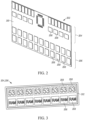
- FIG. 1 depicts an apparatus 100 for providing immersion cooling in a circuit card environment.
- a circuit card 202 includes first and second longitudinally spaced circuit card subassemblies 204 and 206, respectively, connected together into a single, substantially planar circuit card 202 oriented substantially in a lateral-longitudinal plane.
- the circuit card subassemblies 204 and 206 could comprise, as in the example shown in Fig. 2 , two longitudinally spaced groups of IC chips 208 mounted on a single backing substrate 210.
- first and second circuit card subassemblies 204 and 206 can be maintained (via their inclusion in the apparatus 100) in close spatial proximity to each other, each at a different temperature, with low thermal parasitic heat transfer between first and second circuit card subassemblies 204 and 206 due to at least one of the cooling structures described herein and the presence of a portion of the backing substrate 210 longitudinally between the first and second circuit card subassemblies 204 and 206.
- first and second circuit card subassemblies 204 and 206 could comprise at least one IC chip 208 mounted on a subassembly substrate 312, as shown in Fig. 3 .
- the subassembly substrate 312 (before or after the IC chips 208 are mounted thereon) may then be, in turn, mounted on a backing substrate 210 to achieve the desired longitudinal spacing for the first and second circuit card subassemblies 204 and 206.
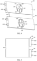
- This "modular" construction (using subassembly substrates 312) is shown in at least Figs. 4 and 6 , and will be presumed throughout the rest of this discussion, for simplicity.
- the backing substrate 210 will be considered to define one suitable lateral-longitudinal plane (e.g., one which is somewhat coincident with the plane of the page in Fig. 1 , other than as tilted to allow for the perspective view of that Figure).
- one suitable lateral-longitudinal plane e.g., one which is somewhat coincident with the plane of the page in Fig. 1 , other than as tilted to allow for the perspective view of that Figure).
- circuit card 202 may help to restrict at least one of magnetic, thermal, and radiation transmission longitudinally between the IC chips 208 of the first and second circuit card subassemblies 204 and 206.
- the backing substrate 210 could act in a heat shielding and electro-magnetic interference ("EMI") shielding capacity.
- EMI electro-magnetic interference
- first and second circuit card subassemblies 204 and 206 may be connected together by a laterally extending card connector (shown and described herein as the backing substrate 210 and/or the subassembly substrate 312) oriented in a parallel lateral-longitudinal plane to the first and second circuit card subassemblies 204 and 206.
- each circuit card subassembly 204 and 205 may include a plurality of 1C chips 208 extending transversely from a subassembly substrate 312.
- Each subassembly substrate 312 is transversely mounted on the card connector (here, backing substrate 210).
- the transverse direction is substantially into and out of the plane of the paper in Fig. 1 .
- the card connector e.g., the backing substrate 210) has a surface area larger than the combined surface area of the subassembly substrates 312 of the first and second circuit card subassemblies 204 and 206. Accordingly, the first and second circuit card subassemblies 204 and 206 may be spaced longitudinally apart, with a longitudinally intervening portion of the card connector, with the assistance of this disparity in relative surface areas.
- the card connector may be less thermally conductive than either of the first and second circuit card subassemblies 204 and 206, which may assist in preventing parasitic heat transfer between the first and second circuit card subassemblies 204 and 206 in some use environments.
- the IC chips 208 of a single circuit card 202 may have different temperature requirements.
- the longitudinally topmost (in the orientation of the Figures) array of IC chips 208 e.g., those on the first circuit card subassembly 204 could have a desired operating temperature in the range of about 2-6K, such as about 4K.
- the longitudinally bottommost (in the orientation of the Figures) array of IC chips 208 e.g., those on the second circuit card subassembly 206) could have a desired operating temperature in the range of about 75-79K, such as about 77K.
- the apparatus 100 can help provide a desired temperature-differential environment for the first and second circuit card subassemblies 204 and 206, and the backing substrate 210 can assist with thermal efficiency by blocking, among other energies, thermal energy transfer longitudinally between the first and second circuit card subassemblies 204 and 206. Having greater physical separation between the first and second first and second circuit card subassemblies 204 and 206 increases the thermal isolation; however, it also increases the signal loss and latency. A balance should be struck, by one of ordinary skill in the art, between acceptable signal loss/latency and thermal isolation to determine the optimal separation for a particular use environment.
- the first and second circuit card subassemblies 204 and 206 may have first and second operating temperatures, respectively.
- the first and second operating temperatures are different from one another.
- a thermal energy transfer device which will be discussed at length below, is operatively connected to an area of the circuit card 202 correlated with a selected one of the first and second circuit card subassemblies 204 and 206. Each thermal energy transfer device at least partially induces the respective, or appropriate, one of the first and second operating temperatures to the selected circuit card subassembly 204 or 206 with which that thermal energy transfer device is associated.
- the thermal energy transfer device transversely overlies at least a supermajority of the selected circuit card subassembly 204 or 206 and is laterally spaced from the other circuit card subassembly 206 or 204, as depicted in the Figures.
- the circuit card 202 and the thermal energy transfer device(s) 114 and/or 116 may be collectively contained in a vacuum ambient environment.
- the thermal energy transfer device may be a first thermal energy transfer device 114.
- the apparatus 100 may also include a second thermal energy transfer device 116 operatively connected to an area of the circuit card 202 correlated with the other one of the first and second circuit card subassemblies 204 and 206 (i.e., not the selected one of the first and second circuit card subassemblies 204 and 206 with which the first thermal energy transfer device 114 is correlated).
- the second thermal energy transfer device 116 may be provided for at least partially inducing the respective, and appropriate, one of the first and second operating temperatures to the other circuit card subassembly 206 or 204.
- the second thermal energy transfer device 116 transversely overlies at least a supermajority of the other circuit card subassembly 206 or 204 and is laterally spaced from the selected circuit card subassembly 204 or 206.
- the thermal energy transfer device(s) 114 and/or 116 may be in direct thermally conductive contact with at least a portion of the selected circuit card subassembly 204 and/or 206 as shown in Fig. 6 , in order to assist with heat transfer between these two structures.
- the thermal energy transfer device(s) 114 and/or 116 is a circulating-coolant heat sink; this is the arrangement shown and described herein.
- the first and second thermal energy transfer devices 114 and 116 are shown in Fig. 4 as including a transparent portion or "window" 418 in a front surface thereof, to allow direct viewing of the first and second circuit card subassemblies 204 and 206 transversely underneath.
- a window 418 could be omitted as desired, and the below description will presume that no window is present.
- Figs. 1 and 5-8 show an assembled apparatus 100.
- the first and second thermal energy transfer devices 114 and 116 are placed into thermally significant proximity with their respective first and second circuit card subassemblies 204 and 206.
- "Thermally significant proximity” is used herein to indicate a degree of physical closeness between the "proximate" structures which facilitates a desired direction, type, and amount of heat transfer.
- thermally significant proximity includes, but is not limited to, one or more of direct contact for thermal conduction and a spaced relationship for thermal convection and/or radiation.
- first and second thermal energy transfer devices 114 and 116 and their respective first and second circuit card subassemblies 204 and 206 may be established and maintained in any desired manner and with any suitable assistance including, but not limited to, one or more of frictional fit, adhesives, mechanical fastener(s) or other attachment structures, gravity, magnetics, soldering/welding, or the like.
- the first and second thermal energy transfer devices 114 and 116 and their respective first and second circuit card subassemblies 204 and 206 could instead be simply held in the desired thermally significant proximity by an external frame or jig.
- One of ordinary skill in the art will be able to produce a suitable apparatus 100 according to aspects of the present invention for a particular use environment.
- the thermal energy transfer device(s) 114 and 116 can have any desired form factor or configuration.
- the thermal energy transfer device(s) 114 and 116 may have a substantially planar or flat surface (e.g., an "underside") which is placed into thermally significant proximity to those structures.
- the thermal energy transfer device(s) 114 and 116 may include a transversely extending thermal lip 720 which is located at least partially in a same lateral-longitudinal plane as the circuit card 202.
- the thermal lip 720 is located laterally and/or longitudinally beside the circuit card 202, such that the thermal lip 720 "hangs" past the circuit card 202 in relation to the remainder of the thermal energy transfer device(s) 114 and 116, as shown in the Figures.
- This thermal lip 720 could be a simple planar extension substantially perpendicular to a remaining portion of the thermal energy transfer device(s) 114 and 116, as shown in the Figures. This arrangement could be used simply for orienting and registering the position of the thermal energy transfer device(s) 114 and 116 with respect to the circuit card 202, and preventing sliding contact between these two structures.
- the thermal lip 720 could instead form at least a portion of a substantially "C”-shaped or hook-shaped structure which wraps around an edge of the circuit card 202, for similar orientation purposes and/or to "snap” or "clip” the thermal energy transfer device(s) to the circuit card 202.
- FIG. 9 is a rear view of the underside 922 of the thermal energy transfer device 114 and/or 116.
- This underside 922 is the surface of the thermal energy transfer device 114 and/or 116 that is in thermally significant proximity to the first and/or second circuit card subassemblies 204 and 206.
- the underside 922 could include one or more thermal pads 924 to assist with heat transfer between the thermal energy transfer device 114 and/or 116 and the circuit card 202.
- thermal pads 924 when present, may each be correlated with the position and/or footprint of one or more IC chips 208, in order to increase heat transfer directly with the corresponding IC chips 208.
- the thermal pads 924 could also or instead have a resilient or cushioning aspect which reduces harmful contact between the IC chips 208 and the thermal energy transfer device 114 and/or 116.
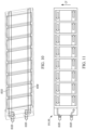
- Fig. 10 is a phantom view of the thermal energy transfer device 114 and/or 116, showing the structures therein.
- the thermal energy transfer device 114 and/or 116 shown in the Figures includes a coolant liquid supply fitting 1026 and a coolant vapor return fitting 1028.
- the coolant liquid supply fitting 1026 and coolant vapor return fitting 1028 can be attached in any desired manner to, respectively, the supply (e.g., liquid supply) and return (e.g., vapor return) lines from a source of fluid coolant (e.g., a Dewar flask).
- a source of fluid coolant e.g., a Dewar flask
- the thermal energy transfer device 114 and/or 116 also includes an internal supply channel, which may be an internal liquid flow channel 1030 in fluid connection with the coolant liquid supply fitting 1026 and an internal return channel, which may be an internal vapor flow channel 1032 in fluid connection with the coolant vapor return fitting 1028.
- an internal supply channel which may be an internal liquid flow channel 1030 in fluid connection with the coolant liquid supply fitting 1026
- an internal return channel which may be an internal vapor flow channel 1032 in fluid connection with the coolant vapor return fitting 1028.
- the internal liquid flow channel 1030 and internal vapor flow channel 1032 are in mutual fluid communication for transfer of at least one of liquid and vapor coolant across at least a portion of a circuit card subassembly 204 and/or 206 in a coolant transfer direction CT substantially within a lateral-longitudinal plane, as shown in Fig. 11 . That is, as shown by the flow arrows in Fig. 11 , the coolant, which may be a liquid coolant, is pumped into the internal supply channel (here, internal liquid flow channel 1030) via the coolant liquid supply fitting 1026.
- the coolant which may be a liquid coolant
- the coolant flows through the interior of the thermal energy transfer device 114 and/or 116 and, as it flows, is at least partially sublimated into vapor coolant, which rises in the coolant transfer direction past the IC chips 208 to "wash" past the chips and thereby remove heat therefrom.
- vapor coolant could become present within any area or portion of an interior of the thermal energy transfer device 114 and/or 116; for example nucleate boiling could occur during the cooling process.
- the vapor coolant, along with any portion of the coolant that remains liquid, is then routed through the internal return channel (here, in a "backward" direction from the supply direction through internal vapor flow channel 1032) for removal from the thermal energy transfer device 114 and/or 116 through the coolant vapor return fitting 1028.
- the coolant is urged through the thermal energy transfer device 114 and/or 116 under negative pressure from the return direction, and/or under positive pressure from the supply direction. It is contemplated that, as previously mentioned, at least a portion of the coolant could remain liquid during this cycle through the thermal energy transfer device 114 and/or 116.
- Figs. 12-14 depict a system 1234 for providing immersion cooling in a circuit card 202 environment.
- the system 1234 includes a plurality of apparatuses 100, which will be shown and described herein as being the type shown in Figs. 1-11 .
- the apparatuses 100 are "stacked" close to each other in the transverse direction, and may be in contact with one or more adjacent apparatuses 100.
- a housing 1236 substantially surrounds the plurality of apparatuses 100 in a transverse-longitudinal plane. That is, the housing is located in front of, behind, and across the top and bottom of at least a portion of each apparatus 100, with the sides of each apparatus 100 being exposed from the housing 1236 to permit cooling fluid, electronic/signal, and/or any other type of suitable connections to an outside agent to be made.
- the housing 1236 could include one or more side-caps (not shown) which could include any desired fluid flow and/or electrical communications apertures or fittings as desired. When present, such side-caps--which may be as simple as plates across the open sides of the housing 1236-could assist with containing the apparatuses 100 for any desired reason, including protection from ambient conditions.
- the side-caps and housing 1236 may be particularly useful when the circuit card 202 and the thermal energy transfer device(s) 114 and 116 are collectively contained in a vacuum ambient environment, which could be at least partially facilitated by the housing 1236 and/or side-caps.
- the entire system 1234 could be located within another enclosure, which itself provides any desired vacuum ambient environment to the apparatuses 100.
- a spacing jig 1238 could be provided to assist with slotting the apparatuses 100 into the housing 1236, particularly if such installation is done via a lateral sliding motion.
- the spacing jig 1238 when present, may be removed from the system 1234 once the apparatuses 100 have been installed into the housing, 1236, or, in some use environments, could remain in place during use of the system 1234.
- Fig. 13 is a partially exploded view of the system 1234, with one apparatus 100 shown removed and exploded into its component parts.
- One or more blocks 1340 could be provided to assist with providing mechanical spacing and/or damping, electrical connections, and/or a thermal path within the system 1234.
- the blocks 1340 shown in Fig. 13 could serve concurrently as connectors for cables running between two or more of the first and second circuit card subassemblies 204 and 206 and at least one backplane (as described below).
- Any structure used as a block 1340 or physical connector within the apparatus could serve as a low conductivity support, and could be liquid crystal polymer, Kevlar, or any other low conductivity material or technique.
- a rack frame, or wedgelock, 1342 can be provided to each apparatus 100 to assist with mounting that apparatus 100 within the housing 1236 and/or with damping vibrations between apparatuses 100 and/or the housing 1236.
- Fig. 13 also schematically depicts a first cooling fluid manifold 1344 for selectively introducing a first cooling fluid into, and selectively removing the first cooling fluid from, the first thermal energy transfer device 114.
- a second cooling fluid manifold 1346 also shown schematically in Fig. 13 , may be provided for selectively introducing a second cooling fluid into, and selectively removing the second cooling fluid from, the second thermal energy transfer device 116.
- One of ordinary skill in the cryogenics arts will be able to provide suitable cooling fluid flow paths, supplies, and piping for a particular use environment of aspects of the present invention.
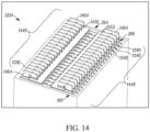
- Fig. 14 the backplane side of the system 1234 is shown; this is the side that is hidden from view on the rear of the depictions in Figs. 12-13 .
- the view of Fig. 14 shows how the blocks 1240 of the first or second circuit card subassemblies 204 or 206 can be employed to facilitate electrical communication via a cabling envelope 1448 which itself is in connection with a respective first or second backplane 1450 or 1452.
- the first and/or second backplanes 1450 and 1452 may also facilitate connection of multiple systems 1234 together, as desired.
- Connectors 1464 could be provided to electrically attach the various portions of the first and/or second circuit card subassemblies 204 or 206 and the first and/or second backplanes 1450 and 1452 together in any desired combination for transmission of power, data, electrical signals, or for any other interconnection purpose, one-way or both ways.
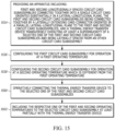
- Fig. 15 is a flowchart summarizing an example method of providing immersion cooling in a circuit card 202 environment using an apparatus 100 and/or a system 1234 as previously discussed.
- first action block 1554 of Fig. 15 an apparatus 100 is provided.
- second action block 1556 of Fig. 15 the first circuit card subassembly 204 is configured for operation at a first operating temperature (e.g., 77K).
- third action block 1558 the second circuit card subassembly 206 is configured for operation at a second operating temperature (e.g., 4K) which is different from the first operating temperature.
- the cooler circuit card subassembly 204 or 206 will normally be located above the warmer circuit card subassembly 204 or 206, when the apparatus 100 is placed in a substantially vertical use position.
- the thermal energy transfer device (here, first thermal energy transfer device 114) is operatively connected to the selected one of the first and second circuit card subassemblies 204 or 206. Then, in fifth action block 1562, the respective one of the first and second operating temperatures is induced to the selected circuit card subassembly 204 or 206 at least partially with the (first) thermal energy transfer device 114.
- the method of Fig. 15 can be carried out before, during, or after assembly of the apparatus 100 into a system 1234, as previously described. The method of Fig. 15 can also or instead be carried out similarly with a plurality of apparatuses 100, sequentially or concurrently.
- another thermal energy transfer device (here, second thermal energy transfer device 116) can likewise be operatively connected to the other one of the first and second circuit card subassemblies 204 or 206.
- second thermal energy transfer device 116 the respective one of the first and second operating temperatures can be induced to the other circuit card subassembly 204 or 206 at least partially with the second thermal energy transfer device 116, analogously to the action in fifth action block 1562 with the first thermal energy transfer device 114.
- the method of Fig. 15 can further include bringing the internal liquid flow channel 1030 and internal vapor flow channel 1032 into mutual fluid communication. At least one of liquid and vapor coolant can then be transferred across at least a portion of a circuit card subassembly 204 and 206, between the internal liquid flow channel 1030 and internal vapor flow channel 1032, in a coolant transfer direction CT substantially within a lateral-longitudinal plane. Therefore, through use of the apparatus 100 and/or system 1234 as shown and described herein, a temperature control scheme, such as immersion cooling, can be carried out as desired.
- a temperature control scheme such as immersion cooling
- references to a structure or feature that is disposed "directly adjacent" another feature may have portions that overlap or underlie the adjacent feature, whereas a structure or feature that is disposed "adjacent" another feature may not have portions that overlap or underlie the adjacent feature.
- spatially relative terms such as “under,” “below,” “lower,” “over,” “upper” and the like, may be used herein for ease of description to describe one element or feature's relationship to another element(s) or feature(s) as illustrated in the figures. It will be understood that the spatially relative terms can encompass different orientations of a device in use or operation, in addition to the orientation depicted in the figures. For example, if a device in the figures is inverted, elements described as “under” or “beneath” other elements or features would then be oriented “over” the other elements or features.
- Any of the described structures and components could be integrally formed as a single unitary or monolithic piece or made up of separate sub-components, with either of these formations involving any suitable stock or bespoke components and/or any suitable material or combinations of materials.
- Any of the described structures and components could be disposable or reusable as desired for a particular use environment.
- Any component could be provided with a user-perceptible marking to indicate a material, configuration, at least one dimension, or the like pertaining to that component, the user-perceptible marking aiding a user in selecting one component from an array of similar components for a particular use environment.
- a "predetermined" status may be determined at any time before the structures being manipulated actually reach that status, the "predetermination" being made as late as immediately before the structure achieves the predetermined status.
Landscapes
- Engineering & Computer Science (AREA)
- Microelectronics & Electronic Packaging (AREA)
- Physics & Mathematics (AREA)
- Thermal Sciences (AREA)
- Theoretical Computer Science (AREA)
- Aviation & Aerospace Engineering (AREA)
- Human Computer Interaction (AREA)
- General Engineering & Computer Science (AREA)
- General Physics & Mathematics (AREA)
- Cooling Or The Like Of Electrical Apparatus (AREA)
Claims (12)
- Eine Vorrichtung (100) zum Bereitstellen einer Eintauchkühlung in einer Umgebung einer Schaltkreiskarte (202), wobei die Vorrichtung (100) Folgendes umfasst:eine Schaltkreiskarte (202) mit ersten und zweiten in Längsrichtung beabstandeten Schaltkreiskarten-Unterbaugruppen (204, 206), die miteinander zu einer einzigen Schaltkreiskarte (202) verbunden sind, die im Wesentlichen in einer Quer-Längsebene ausgerichtet ist, wobei die ersten und zweiten Schaltkreiskarten-Unterbaugruppen (204, 206) durch einen sich seitlich erstreckenden Kartenverbinder (210, 321) miteinander verbunden sind, der in einer parallelen Quer-Längsebene zu den ersten und zweiten Schaltkreiskarten-Unterbaugruppen (204, 206) ausgerichtet ist, wobei die ersten und zweiten Schaltkreiskarten-Unterbaugruppen (204, 206) erste bzw. zweite Betriebstemperaturen aufweisen, wobei die ersten und zweiten Betriebstemperaturen voneinander verschieden sind; undeine Vorrichtung zur Übertragung thermischer Energie (114, 116), die betriebsmäßig mit einem Bereich der Schaltkreiskarte (202) verbunden ist, der mit einer ausgewählten der ersten und zweiten Schaltkreiskarten-Unterbaugruppe (204, 206) korreliert, wobei die Vorrichtung zur Übertragung thermischer Energie (114, 116) eine Zirkulationskühlmittel-Wärmesenke ist, wobei die Vorrichtung zur Übertragung thermischer Energie (114, 116) zumindest teilweise die jeweilige der ersten und zweiten Betriebstemperaturen auf die ausgewählte Schaltkreiskarten-Unterbaugruppe (204, 206) induziert, wobei die Vorrichtung zur Übertragung thermischer Energie (114, 116) quer über mindestens einem Großteil der ausgewählten Schaltkreiskarten-Unterbaugruppe (204, 206) liegt und seitlich von der anderen Schaltkreiskarten-Unterbaugruppe (204, 206) beabstandet ist, wobei die Vorrichtung zur Übertragung thermischer Energie (114, 116) eine erste Vorrichtung zur Übertragung thermischer Energie (114) ist, und eine zweite Vorrichtung zur Übertragung thermischer Energie (116) enthält, die betriebsmäßig mit einem Bereich der Schaltkreiskarte (202) verbunden ist, der mit der anderen der ersten und zweiten Schaltkreiskarten-Unterbaugruppen (204, 206) korreliert ist, wobei die zweite Vorrichtung zur Übertragung thermischer Energie (116) zumindest teilweise die jeweilige der ersten und zweiten Betriebstemperaturen auf die andere Schaltkreiskarten-Unterbaugruppe (204, 206) induziert, die zweite Vorrichtung zur Übertragung thermischer Energie (116) quer über mindestens einen überwiegenden Teil der anderen Schaltkreiskarten-Unterbaugruppe (204, 206) liegt und seitlich von der ausgewählten Schaltkreiskarten-Unterbaugruppe (204, 206) beabstandet ist, wobei eine der ersten und zweiten Betriebstemperaturen im Bereich von etwa 2 bis 6 K, insbesondere etwa 4 K, liegt und die andere der ersten und zweiten Betriebstemperaturen im Bereich von etwa 75 bis 79 K, insbesondere etwa 77 K, liegt.
- Die Vorrichtung (100) nach Anspruch 1, wobei die Vorrichtung zur Übertragung thermischer Energie (114, 116) eine Kühlflüssigkeitszufuhrarmatur (1026) und eine Kühlmitteldampfrückführarmatur (1028) umfasst.
- Die Vorrichtung (100) nach Anspruch 2, wobei die Vorrichtung zur Übertragung thermischer Energie (114, 116) einen internen Flüssigkeitsströmungskanal (1030) in Fluidverbindung mit dem Kühlflüssigkeitszuführungsanschluss (1026) und einen internen Dampfströmungskanal (1032) in Fluidverbindung mit dem Kühlmitteldampfrückführungsanschluss (1028) aufweist, wobei der innere Flüssigkeitsströmungskanal (1030) und der innere Dampfströmungskanal (1032) in gegenseitiger Fluidverbindung stehen, um mindestens eines von flüssigem und dampfförmigem Kühlmittel über mindestens einen Teil einer Schaltkreiskarten-Unterbaugruppe (204, 206) in einer Kühlmittelübertragungsrichtung im Wesentlichen innerhalb einer Quer-Längsebene zu übertragen.
- Die Vorrichtung (100) nach Anspruch 1, wobei die Vorrichtung zur Übertragung thermischer Energie (114, 116) in direktem wärmeleitendem Kontakt mit mindestens einem Teil der ausgewählten Schaltkreiskarten-Unterbaugruppe (204, 206) steht.
- Die Vorrichtung (100) nach Anspruch 1, wobei jede Schaltkreiskarten-Unterbaugruppe (204, 206) eine Vielzahl von IC-Chips (208) enthält, die sich quer von einem Unterbaugruppensubstrat (312) erstrecken, wobei jedes Unterbaugruppensubstrat (312) quer auf dem Kartenverbinder (210, 312) montiert ist, wobei der Kartenverbinder (210, 312) eine Oberfläche aufweist, die größer ist als die kombinierte Oberfläche der Unterbaugruppensubstrate (312) der ersten und zweiten Schaltkreiskarten-Unterbaugruppen (204, 206).
- Die Vorrichtung (100) nach Anspruch 1, wobei die Vorrichtung zur Übertragung thermischer Energie (114, 116) eine sich quer erstreckende thermische Lippe (720) aufweist, die zumindest teilweise in derselben Quer-Längsebene wie die Schaltkreiskarte (202) angeordnet ist.
- Ein Verfahren zur Bereitstellung einer Eintauchkühlung in der Umgebung einer Schaltkreiskarte (202), wobei das Verfahren Folgendes umfasst:
Bereitstellen einer Vorrichtung (100), die Folgendes umfasst:erste und zweite in Längsrichtung beabstandete Schaltkreiskarten-Unterbaugruppen (204, 206), die miteinander zu einer einzigen Schaltkreiskarte (202) verbunden sind, die im Wesentlichen in einer Quer-Längsebene ausgerichtet ist, wobei die ersten und zweiten Schaltkreiskarten-Unterbaugruppen (204, 206) durch einen sich seitlich erstreckenden Kartenverbinder (210, 312) miteinander verbunden sind, der in einer parallelen Quer-Längsebene zu den ersten und zweiten Schaltkreiskarten-Unterbaugruppen (204, 206) ausgerichtet ist, undeine Vorrichtung zur Übertragung thermischer Energie (114, 116), die quer über mindestens einem überwiegenden Teil einer ausgewählten der ersten und zweiten Schaltkreiskarten-Unterbaugruppen (204, 206) liegt und seitlich von einer anderen Schaltkreiskarten-Unterbaugruppe (204, 206) beabstandet ist, wobei die Vorrichtung zur Übertragung thermischer Energie (114, 116) eine Zirkulationskühlmittel-Wärmesenke ist;Konfigurieren der ersten Schaltkreiskarten-Unterbaugruppe (204) für den Betrieb bei einer ersten Betriebstemperatur;Konfigurieren der zweiten Schaltkreiskarten-Unterbaugruppe (206) für den Betrieb bei einer zweiten Betriebstemperatur, die sich von der ersten Betriebstemperatur unterscheidet;operatives Verbinden der Vorrichtung zur Übertragung thermischer Energie (114, 116) mit der ausgewählten der ersten und zweiten Schaltkreiskarten-Unterbaugruppen (204, 206); undInduzieren der jeweiligen der ersten und zweiten Betriebstemperaturen auf die ausgewählte Schaltkreiskarten-Unterbaugruppe (204, 206) zumindest teilweise mit der Vorrichtung zur Übertragung thermischer Energie (114, 116), wobei die Vorrichtung zur Übertragung thermischer Energie (114, 116) eine erste Vorrichtung zur Übertragung thermischer Energie (114) ist und eine zweite Vorrichtung zur Übertragung thermischer Energie (116) enthält, die betriebsmäßig mit einem Bereich der Schaltkreiskarte (202) verbunden ist, der mit der anderen der ersten und zweiten Schaltkreiskarten-Unterbaugruppen (204, 206) korreliert ist, die zweite Vorrichtung zur Übertragung thermischer Energie (116) zumindest teilweise die jeweilige der ersten und zweiten Betriebstemperaturen auf die andere Schaltkreiskarten-Unterbaugruppe (204, 206) induziert, wobei die zweite Vorrichtung zur Übertragung thermischer Energie (116) quer über zumindest einen überwiegenden Teil der anderen Schaltkreiskarten-Unterbaugruppe (204, 206) liegt und seitlich beabstandet ist, 206) liegt und seitlich von der ausgewählten Schaltkreiskarten-Unterbaugruppe (204, 206) beabstandet ist, wobei eine der ersten und zweiten Betriebstemperaturen im Bereich von etwa 2-6 K, insbesondere etwa 4 K, liegt und die andere der ersten und zweiten Betriebstemperaturen im Bereich von etwa 75-79 K, insbesondere etwa 77 K, liegt. - Das Verfahren nach Anspruch 7, wobei
Bereitstellen einer Vorrichtung (100), die Folgendes umfasst:Bereitstellen der Vorrichtung zur Übertragung thermischer Energie (114, 116) als erste Vorrichtung zur Übertragung thermischer Energie (114), undBereitstellen einer zweiten thermischen Energieübertragungsvorrichtung (116), die quer über mindestens einem überwiegenden Teil der anderen der ersten und zweiten Schaltkreiskarten-Unterbaugruppen (204, 206) liegt und seitlich von der ausgewählten Schaltkreiskarten-Unterbaugruppe (204, 206) beabstandet ist; unddas Verfahren ferner umfasst:operatives Verbinden der zweiten Vorrichtung zur Übertragung thermischer Energie (116) mit der anderen der ersten und zweiten Schaltkreiskarten-Unterbaugruppen (204, 206); undHerbeiführen der jeweiligen ersten oder zweiten Betriebstemperatur an der anderen Schaltkreiskarten-Unterbaugruppe (204, 206) zumindest teilweise mit der zweiten Vorrichtung zur Übertragung thermischer Energie (116). - Verfahren nach Anspruch 7, wobei das Bereitstellen einer Vorrichtung (100) das Versehen der thermischen Energieübertragungsvorrichtung (114, 116) mit einem Kühlflüssigkeitszuführungsanschluss (1026) und einem Kühlmitteldampfrückführungsanschluss (1028) umfasst.
- Das Verfahren nach Anspruch 9, wobei das Bereitstellen einer Vorrichtung (100) Folgendes umfasst:
Versehen der thermischen Energieübertragungsvorrichtung (114, 116) mit einem internen Flüssigkeitsströmungskanal (1030) in Fluidverbindung mit dem Kühlflüssigkeitszufuhranschluss (1026) und einem internen Dampfströmungskanal (1032) in Fluidverbindung mit dem Kühlmitteldampfrücklaufanschluss (1028); und das Verfahren ferner umfasst:Bringen des internen Flüssigkeitsströmungskanals (1030) und des internen Dampfströmungskanals (1032) in gegenseitige Fluidverbindung; undÜbertragen von flüssigem und/oder dampfförmigem Kühlmittel über mindestens einen Teil einer Schaltkreiskarten-Unterbaugruppe (204, 206) zwischen dem internen Flüssigkeitsströmungskanal (1030) und dem internen Dampfströmungskanal (1032) in einer Kühlmittelübertragungsrichtung im Wesentlichen innerhalb einer Quer-Längsebene. - Das Verfahren nach Anspruch 7, wobei das Bereitstellen einer Vorrichtung (100) das Platzieren der Vorrichtung zur Übertragung thermischer Energie (114, 116) in direktem wärmeleitendem Kontakt mit mindestens einem Teil der ausgewählten Schaltkreiskarten-Unterbaugruppe (204, 206) umfasst.
- Das Verfahren nach Anspruch 7, bei dem das operative Verbinden der zweiten Vorrichtung zur Übertragung thermischer Energie (116) mit der anderen der ersten und zweiten Schaltkreiskarten-Unterbaugruppen (204, 206) das Anordnen einer sich quer erstreckenden thermischen Lippe (720) der Vorrichtung zur Übertragung thermischer Energie (114, 116) zumindest teilweise in derselben Quer-Längsebene wie die Schaltkreiskarte (202) umfasst.
Applications Claiming Priority (2)
| Application Number | Priority Date | Filing Date | Title |
|---|---|---|---|
| US15/916,019 US10438867B2 (en) | 2018-03-08 | 2018-03-08 | Immersion cooling temperature control method, system, and apparatus |
| PCT/US2019/018766 WO2019173051A1 (en) | 2018-03-08 | 2019-02-20 | Immersion cooling temperature control method, system, and apparatus |
Publications (2)
| Publication Number | Publication Date |
|---|---|
| EP3763178A1 EP3763178A1 (de) | 2021-01-13 |
| EP3763178B1 true EP3763178B1 (de) | 2025-06-25 |
Family
ID=65686945
Family Applications (1)
| Application Number | Title | Priority Date | Filing Date |
|---|---|---|---|
| EP19709605.0A Active EP3763178B1 (de) | 2018-03-08 | 2019-02-20 | Tauchkühlung verfahren, system und vorrichtung zur temperaturregelung |
Country Status (7)
| Country | Link |
|---|---|
| US (1) | US10438867B2 (de) |
| EP (1) | EP3763178B1 (de) |
| JP (2) | JP7232838B2 (de) |
| KR (1) | KR102461709B1 (de) |
| AU (2) | AU2019229950B2 (de) |
| CA (1) | CA3091112C (de) |
| WO (1) | WO2019173051A1 (de) |
Families Citing this family (5)
| Publication number | Priority date | Publication date | Assignee | Title |
|---|---|---|---|---|
| US10782258B2 (en) | 2018-09-04 | 2020-09-22 | Northrop Grumman Systems Corporation | Superconductor critical temperature measurement |
| NL2025918B1 (en) * | 2020-06-25 | 2022-02-22 | Microsoft Technology Licensing Llc | Systems and methods of improving thermal management of heat-generation components |
| US11647607B2 (en) | 2021-01-22 | 2023-05-09 | Cisco Technology, Inc. | Localized immersion cooling enclosure with thermal efficiency features |
| TWI793757B (zh) * | 2021-09-09 | 2023-02-21 | 緯創資通股份有限公司 | 浸沒式冷卻系統及冷卻裝置 |
| US20250261318A1 (en) * | 2024-02-09 | 2025-08-14 | Verizon Patent And Licensing Inc. | Networking apparatus |
Citations (1)
| Publication number | Priority date | Publication date | Assignee | Title |
|---|---|---|---|---|
| US20140146467A1 (en) * | 2012-11-26 | 2014-05-29 | International Business Machines Corporation | Immersion-cooled and conduction-cooled electronic system |
Family Cites Families (28)
| Publication number | Priority date | Publication date | Assignee | Title |
|---|---|---|---|---|
| US4865331A (en) | 1988-09-15 | 1989-09-12 | Ncr Corporation | Differential temperature seal |
| US4962444A (en) | 1989-01-03 | 1990-10-09 | Sunstrand Corporation | Cold chassis for cooling electronic circuit components on an electronic board |
| JPH077188A (ja) | 1993-06-18 | 1995-01-10 | Hitachi Ltd | 複合動作環境用実装装置 |
| US5329428A (en) * | 1993-06-21 | 1994-07-12 | International Business Machines Corporation | High-density packaging for multiple removable electronics subassemblies |
| US6052284A (en) * | 1996-08-06 | 2000-04-18 | Advantest Corporation | Printed circuit board with electronic devices mounted thereon |
| DE10138711B4 (de) | 2000-10-02 | 2009-12-31 | Siemens Ag | Kühlanordnung für in einem Gehäuse angeordnete Verlustwärme erzeugende elektrische Bauteile und elektrisches Gerät mit einer derartigen Kühlanordnung |
| US6616469B2 (en) | 2001-03-12 | 2003-09-09 | Tyco Electronics Logistics Ag | Electrical and fluid interconnect |
| US6646879B2 (en) * | 2001-05-16 | 2003-11-11 | Cray Inc. | Spray evaporative cooling system and method |
| US7236363B2 (en) | 2003-09-22 | 2007-06-26 | Hewlett-Packard Development Company, L.P. | Liquid cooled system module |
| JP2007049015A (ja) | 2005-08-11 | 2007-02-22 | Nec Corp | 電子機器構造と、電子機器構造が用いられた電子機器 |
| JP5149706B2 (ja) | 2008-06-13 | 2013-02-20 | 三菱電機株式会社 | 開閉装置のトリップ操作回路の断線検出装置 |
| US20090323286A1 (en) * | 2008-06-13 | 2009-12-31 | Evga Corporation | Apparatus for removing heat from pc circuit board devices such as graphics cards and the like |
| FR2938774A1 (fr) | 2008-11-27 | 2010-05-28 | Parrot | Dispositif de pilotage d'un drone |
| JP5223712B2 (ja) | 2009-02-12 | 2013-06-26 | パナソニック株式会社 | 圧縮機用電子回路装置 |
| US9629280B2 (en) | 2010-06-24 | 2017-04-18 | Raytheon Company | Multiple liquid loop cooling for electronics |
| JP5857964B2 (ja) | 2010-08-31 | 2016-02-10 | 日本電気株式会社 | 電子機器冷却システム |
| JP2012164874A (ja) | 2011-02-08 | 2012-08-30 | Toyota Motor Corp | 冷却装置および冷却ユニット |
| US8780556B1 (en) | 2012-03-26 | 2014-07-15 | Lochheed Martin Corporation | Fluid actuated cooling card retainer |
| JP6293152B2 (ja) | 2012-09-25 | 2018-03-14 | リキッドクール ソリューションズ, インク. | 浸漬型電子デバイスのアレイ用冷却剤の圧力および液流を管理する方法および装置 |
| US20140316614A1 (en) | 2012-12-17 | 2014-10-23 | David L. Newman | Drone for collecting images and system for categorizing image data |
| CA2902045A1 (en) | 2013-02-22 | 2014-08-28 | Thalmic Labs Inc. | Methods and devices that combine muscle activity sensor signals and inertial sensor signals for gesture-based control |
| CN103426282A (zh) | 2013-07-31 | 2013-12-04 | 深圳市大疆创新科技有限公司 | 遥控方法及终端 |
| JP6155988B2 (ja) * | 2013-09-02 | 2017-07-05 | 富士通株式会社 | 情報処理装置 |
| JP2016054248A (ja) | 2014-09-04 | 2016-04-14 | 富士通株式会社 | 冷却モジュール、冷却モジュール搭載基板および電子機器 |
| US20180166621A1 (en) * | 2015-06-10 | 2018-06-14 | Gentherm Inc. | Vehicle battery thermoelectric device with integrated cold plate assembly |
| JP6627327B2 (ja) | 2015-08-21 | 2020-01-08 | 日本電気株式会社 | 冷却装置および冷却方法 |
| US9681533B2 (en) | 2015-11-17 | 2017-06-13 | Northrop Grumman Systems Corporation | Apparatus and method for providing a temperature-differential circuit card environment |
| US9648749B1 (en) | 2015-11-17 | 2017-05-09 | Northrop Grumman Systems Corporation | Circuit card assembly and method of providing same |
-
2018
- 2018-03-08 US US15/916,019 patent/US10438867B2/en active Active
-
2019
- 2019-02-20 WO PCT/US2019/018766 patent/WO2019173051A1/en not_active Ceased
- 2019-02-20 JP JP2020544810A patent/JP7232838B2/ja active Active
- 2019-02-20 CA CA3091112A patent/CA3091112C/en active Active
- 2019-02-20 KR KR1020207025944A patent/KR102461709B1/ko active Active
- 2019-02-20 EP EP19709605.0A patent/EP3763178B1/de active Active
- 2019-02-20 AU AU2019229950A patent/AU2019229950B2/en not_active Ceased
-
2021
- 2021-04-07 AU AU2021202125A patent/AU2021202125A1/en not_active Abandoned
-
2022
- 2022-10-20 JP JP2022168194A patent/JP7520937B2/ja active Active
Patent Citations (1)
| Publication number | Priority date | Publication date | Assignee | Title |
|---|---|---|---|---|
| US20140146467A1 (en) * | 2012-11-26 | 2014-05-29 | International Business Machines Corporation | Immersion-cooled and conduction-cooled electronic system |
Also Published As
| Publication number | Publication date |
|---|---|
| AU2021202125A1 (en) | 2021-05-06 |
| AU2019229950A1 (en) | 2020-09-03 |
| EP3763178A1 (de) | 2021-01-13 |
| WO2019173051A1 (en) | 2019-09-12 |
| KR102461709B1 (ko) | 2022-11-01 |
| US10438867B2 (en) | 2019-10-08 |
| US20190279916A1 (en) | 2019-09-12 |
| JP7232838B2 (ja) | 2023-03-03 |
| JP2021515315A (ja) | 2021-06-17 |
| KR20200120678A (ko) | 2020-10-21 |
| AU2019229950B2 (en) | 2021-04-01 |
| CA3091112A1 (en) | 2019-09-12 |
| JP7520937B2 (ja) | 2024-07-23 |
| JP2023017788A (ja) | 2023-02-07 |
| CA3091112C (en) | 2023-01-24 |
Similar Documents
| Publication | Publication Date | Title |
|---|---|---|
| CA3091112C (en) | Immersion cooling temperature control method, system, and apparatus | |
| CA2743110C (en) | Liquid-cooled cooling apparatus, electronics rack and methods of fabrication thereof | |
| US7641101B2 (en) | Method of assembling a cooling system for a multi-component electronics system | |
| AU2019257568B2 (en) | Device and method for providing immersion cooling in a compact-format circuit card environment | |
| EP2525632B1 (de) | Systeme für Leiterplatten-Wärmeübertrag und Verfahren zum Zusammenbau davon | |
| CA3094371C (en) | Forced flow cooling temperature control method, system, and apparatus | |
| JP5797329B2 (ja) | 冷却システムを備えた電子計算機 | |
| EP3378291B1 (de) | Vorrichtung und verfahren zur bereitstellung einer temperaturdifferenz-chipkartenumgebung | |
| US20220418170A1 (en) | Chassis with thermal transfer fluid path | |
| US10595441B1 (en) | Method and apparatus for separating a thermal load path from a structural load path in a circuit board environment | |
| US20230115186A1 (en) | Enclosure for electronic device with liquid cooling |
Legal Events
| Date | Code | Title | Description |
|---|---|---|---|
| STAA | Information on the status of an ep patent application or granted ep patent |
Free format text: STATUS: UNKNOWN |
|
| STAA | Information on the status of an ep patent application or granted ep patent |
Free format text: STATUS: THE INTERNATIONAL PUBLICATION HAS BEEN MADE |
|
| PUAI | Public reference made under article 153(3) epc to a published international application that has entered the european phase |
Free format text: ORIGINAL CODE: 0009012 |
|
| STAA | Information on the status of an ep patent application or granted ep patent |
Free format text: STATUS: REQUEST FOR EXAMINATION WAS MADE |
|
| 17P | Request for examination filed |
Effective date: 20200904 |
|
| AK | Designated contracting states |
Kind code of ref document: A1 Designated state(s): AL AT BE BG CH CY CZ DE DK EE ES FI FR GB GR HR HU IE IS IT LI LT LU LV MC MK MT NL NO PL PT RO RS SE SI SK SM TR |
|
| AX | Request for extension of the european patent |
Extension state: BA ME |
|
| DAV | Request for validation of the european patent (deleted) | ||
| DAX | Request for extension of the european patent (deleted) | ||
| STAA | Information on the status of an ep patent application or granted ep patent |
Free format text: STATUS: EXAMINATION IS IN PROGRESS |
|
| 17Q | First examination report despatched |
Effective date: 20211014 |
|
| P01 | Opt-out of the competence of the unified patent court (upc) registered |
Effective date: 20230607 |
|
| GRAP | Despatch of communication of intention to grant a patent |
Free format text: ORIGINAL CODE: EPIDOSNIGR1 |
|
| STAA | Information on the status of an ep patent application or granted ep patent |
Free format text: STATUS: GRANT OF PATENT IS INTENDED |
|
| INTG | Intention to grant announced |
Effective date: 20250116 |
|
| RIN1 | Information on inventor provided before grant (corrected) |
Inventor name: KIRKWOOD, KEITH R. Inventor name: WAKAMIYA, STANLEY KATSUYOSHI Inventor name: HEFFNER, HARLAN CRAIG Inventor name: CHOROSINSKI, LEONARD GEORGE Inventor name: CHRISTIANSEN, MARTIN BROKNER |
|
| GRAS | Grant fee paid |
Free format text: ORIGINAL CODE: EPIDOSNIGR3 |
|
| GRAA | (expected) grant |
Free format text: ORIGINAL CODE: 0009210 |
|
| STAA | Information on the status of an ep patent application or granted ep patent |
Free format text: STATUS: THE PATENT HAS BEEN GRANTED |
|
| AK | Designated contracting states |
Kind code of ref document: B1 Designated state(s): AL AT BE BG CH CY CZ DE DK EE ES FI FR GB GR HR HU IE IS IT LI LT LU LV MC MK MT NL NO PL PT RO RS SE SI SK SM TR |
|
| REG | Reference to a national code |
Ref country code: GB Ref legal event code: FG4D |
|
| REG | Reference to a national code |
Ref country code: CH Ref legal event code: EP |
|
| REG | Reference to a national code |
Ref country code: CH Ref legal event code: EP |
|
| REG | Reference to a national code |
Ref country code: IE Ref legal event code: FG4D |
|
| REG | Reference to a national code |
Ref country code: DE Ref legal event code: R096 Ref document number: 602019071505 Country of ref document: DE |
|
| PG25 | Lapsed in a contracting state [announced via postgrant information from national office to epo] |
Ref country code: FI Free format text: LAPSE BECAUSE OF FAILURE TO SUBMIT A TRANSLATION OF THE DESCRIPTION OR TO PAY THE FEE WITHIN THE PRESCRIBED TIME-LIMIT Effective date: 20250625 |
|
| REG | Reference to a national code |
Ref country code: LT Ref legal event code: MG9D |
|
| PG25 | Lapsed in a contracting state [announced via postgrant information from national office to epo] |
Ref country code: GR Free format text: LAPSE BECAUSE OF FAILURE TO SUBMIT A TRANSLATION OF THE DESCRIPTION OR TO PAY THE FEE WITHIN THE PRESCRIBED TIME-LIMIT Effective date: 20250926 Ref country code: NO Free format text: LAPSE BECAUSE OF FAILURE TO SUBMIT A TRANSLATION OF THE DESCRIPTION OR TO PAY THE FEE WITHIN THE PRESCRIBED TIME-LIMIT Effective date: 20250925 |
|
| PG25 | Lapsed in a contracting state [announced via postgrant information from national office to epo] |
Ref country code: BG Free format text: LAPSE BECAUSE OF FAILURE TO SUBMIT A TRANSLATION OF THE DESCRIPTION OR TO PAY THE FEE WITHIN THE PRESCRIBED TIME-LIMIT Effective date: 20250625 |
|
| PG25 | Lapsed in a contracting state [announced via postgrant information from national office to epo] |
Ref country code: HR Free format text: LAPSE BECAUSE OF FAILURE TO SUBMIT A TRANSLATION OF THE DESCRIPTION OR TO PAY THE FEE WITHIN THE PRESCRIBED TIME-LIMIT Effective date: 20250625 |
|
| PG25 | Lapsed in a contracting state [announced via postgrant information from national office to epo] |
Ref country code: RS Free format text: LAPSE BECAUSE OF FAILURE TO SUBMIT A TRANSLATION OF THE DESCRIPTION OR TO PAY THE FEE WITHIN THE PRESCRIBED TIME-LIMIT Effective date: 20250925 |
|
| PG25 | Lapsed in a contracting state [announced via postgrant information from national office to epo] |
Ref country code: LV Free format text: LAPSE BECAUSE OF FAILURE TO SUBMIT A TRANSLATION OF THE DESCRIPTION OR TO PAY THE FEE WITHIN THE PRESCRIBED TIME-LIMIT Effective date: 20250625 |
|
| REG | Reference to a national code |
Ref country code: NL Ref legal event code: MP Effective date: 20250625 |
|
| PG25 | Lapsed in a contracting state [announced via postgrant information from national office to epo] |
Ref country code: NL Free format text: LAPSE BECAUSE OF FAILURE TO SUBMIT A TRANSLATION OF THE DESCRIPTION OR TO PAY THE FEE WITHIN THE PRESCRIBED TIME-LIMIT Effective date: 20250625 |
|
| PG25 | Lapsed in a contracting state [announced via postgrant information from national office to epo] |
Ref country code: PT Free format text: LAPSE BECAUSE OF FAILURE TO SUBMIT A TRANSLATION OF THE DESCRIPTION OR TO PAY THE FEE WITHIN THE PRESCRIBED TIME-LIMIT Effective date: 20251027 |
|
| REG | Reference to a national code |
Ref country code: AT Ref legal event code: MK05 Ref document number: 1808053 Country of ref document: AT Kind code of ref document: T Effective date: 20250625 |
|
| PG25 | Lapsed in a contracting state [announced via postgrant information from national office to epo] |
Ref country code: IS Free format text: LAPSE BECAUSE OF FAILURE TO SUBMIT A TRANSLATION OF THE DESCRIPTION OR TO PAY THE FEE WITHIN THE PRESCRIBED TIME-LIMIT Effective date: 20251025 |
|
| PG25 | Lapsed in a contracting state [announced via postgrant information from national office to epo] |
Ref country code: AT Free format text: LAPSE BECAUSE OF FAILURE TO SUBMIT A TRANSLATION OF THE DESCRIPTION OR TO PAY THE FEE WITHIN THE PRESCRIBED TIME-LIMIT Effective date: 20250625 Ref country code: SM Free format text: LAPSE BECAUSE OF FAILURE TO SUBMIT A TRANSLATION OF THE DESCRIPTION OR TO PAY THE FEE WITHIN THE PRESCRIBED TIME-LIMIT Effective date: 20250625 |
|
| PG25 | Lapsed in a contracting state [announced via postgrant information from national office to epo] |
Ref country code: CZ Free format text: LAPSE BECAUSE OF FAILURE TO SUBMIT A TRANSLATION OF THE DESCRIPTION OR TO PAY THE FEE WITHIN THE PRESCRIBED TIME-LIMIT Effective date: 20250625 |
|
| PG25 | Lapsed in a contracting state [announced via postgrant information from national office to epo] |
Ref country code: PL Free format text: LAPSE BECAUSE OF FAILURE TO SUBMIT A TRANSLATION OF THE DESCRIPTION OR TO PAY THE FEE WITHIN THE PRESCRIBED TIME-LIMIT Effective date: 20250625 |
|
| PG25 | Lapsed in a contracting state [announced via postgrant information from national office to epo] |
Ref country code: EE Free format text: LAPSE BECAUSE OF FAILURE TO SUBMIT A TRANSLATION OF THE DESCRIPTION OR TO PAY THE FEE WITHIN THE PRESCRIBED TIME-LIMIT Effective date: 20250625 |
|
| PG25 | Lapsed in a contracting state [announced via postgrant information from national office to epo] |
Ref country code: SK Free format text: LAPSE BECAUSE OF FAILURE TO SUBMIT A TRANSLATION OF THE DESCRIPTION OR TO PAY THE FEE WITHIN THE PRESCRIBED TIME-LIMIT Effective date: 20250625 |
|
| PG25 | Lapsed in a contracting state [announced via postgrant information from national office to epo] |
Ref country code: ES Free format text: LAPSE BECAUSE OF FAILURE TO SUBMIT A TRANSLATION OF THE DESCRIPTION OR TO PAY THE FEE WITHIN THE PRESCRIBED TIME-LIMIT Effective date: 20250625 |
|
| REG | Reference to a national code |
Ref country code: CH Ref legal event code: U11 Free format text: ST27 STATUS EVENT CODE: U-0-0-U10-U11 (AS PROVIDED BY THE NATIONAL OFFICE) Effective date: 20260301 |
|
| REG | Reference to a national code |
Ref country code: DE Ref legal event code: R097 Ref document number: 602019071505 Country of ref document: DE |
|
| PG25 | Lapsed in a contracting state [announced via postgrant information from national office to epo] |
Ref country code: DK Free format text: LAPSE BECAUSE OF FAILURE TO SUBMIT A TRANSLATION OF THE DESCRIPTION OR TO PAY THE FEE WITHIN THE PRESCRIBED TIME-LIMIT Effective date: 20250625 |
|
| PG25 | Lapsed in a contracting state [announced via postgrant information from national office to epo] |
Ref country code: IT Free format text: LAPSE BECAUSE OF FAILURE TO SUBMIT A TRANSLATION OF THE DESCRIPTION OR TO PAY THE FEE WITHIN THE PRESCRIBED TIME-LIMIT Effective date: 20250625 |
|
| PGFP | Annual fee paid to national office [announced via postgrant information from national office to epo] |
Ref country code: FR Payment date: 20260218 Year of fee payment: 8 |
|
| PGFP | Annual fee paid to national office [announced via postgrant information from national office to epo] |
Ref country code: CH Payment date: 20260301 Year of fee payment: 8 |
|
| PLBE | No opposition filed within time limit |
Free format text: ORIGINAL CODE: 0009261 |
|
| STAA | Information on the status of an ep patent application or granted ep patent |
Free format text: STATUS: NO OPPOSITION FILED WITHIN TIME LIMIT |
|
| REG | Reference to a national code |
Ref country code: CH Ref legal event code: L10 Free format text: ST27 STATUS EVENT CODE: U-0-0-L10-L00 (AS PROVIDED BY THE NATIONAL OFFICE) Effective date: 20260507 |
|
| 26N | No opposition filed |
Effective date: 20260326 |
|
| PG25 | Lapsed in a contracting state [announced via postgrant information from national office to epo] |
Ref country code: LT Free format text: LAPSE BECAUSE OF FAILURE TO SUBMIT A TRANSLATION OF THE DESCRIPTION OR TO PAY THE FEE WITHIN THE PRESCRIBED TIME-LIMIT Effective date: 20250625 |
|
| PG25 | Lapsed in a contracting state [announced via postgrant information from national office to epo] |
Ref country code: SE Free format text: LAPSE BECAUSE OF FAILURE TO SUBMIT A TRANSLATION OF THE DESCRIPTION OR TO PAY THE FEE WITHIN THE PRESCRIBED TIME-LIMIT Effective date: 20250625 |