EP3762583B1 - In-situ-verfahren zur erzeugung von synthesegas aus unterirdischen kohlenwasserstoffreservoirs - Google Patents
In-situ-verfahren zur erzeugung von synthesegas aus unterirdischen kohlenwasserstoffreservoirs Download PDFInfo
- Publication number
- EP3762583B1 EP3762583B1 EP19764420.6A EP19764420A EP3762583B1 EP 3762583 B1 EP3762583 B1 EP 3762583B1 EP 19764420 A EP19764420 A EP 19764420A EP 3762583 B1 EP3762583 B1 EP 3762583B1
- Authority
- EP
- European Patent Office
- Prior art keywords
- reservoir
- petroleum
- synthesis gas
- heating
- well
- Prior art date
- Legal status (The legal status is an assumption and is not a legal conclusion. Google has not performed a legal analysis and makes no representation as to the accuracy of the status listed.)
- Active
Links
Images


Classifications
-
- E—FIXED CONSTRUCTIONS
- E21—EARTH OR ROCK DRILLING; MINING
- E21B—EARTH OR ROCK DRILLING; OBTAINING OIL, GAS, WATER, SOLUBLE OR MELTABLE MATERIALS OR A SLURRY OF MINERALS FROM WELLS
- E21B43/00—Methods or apparatus for obtaining oil, gas, water, soluble or meltable materials or a slurry of minerals from wells
- E21B43/16—Enhanced recovery methods for obtaining hydrocarbons
- E21B43/24—Enhanced recovery methods for obtaining hydrocarbons using heat, e.g. steam injection
- E21B43/2401—Enhanced recovery methods for obtaining hydrocarbons using heat, e.g. steam injection by means of electricity
-
- C—CHEMISTRY; METALLURGY
- C01—INORGANIC CHEMISTRY
- C01B—NON-METALLIC ELEMENTS; COMPOUNDS THEREOF; METALLOIDS OR COMPOUNDS THEREOF NOT COVERED BY SUBCLASS C01C
- C01B3/00—Hydrogen; Gaseous mixtures containing hydrogen; Separation of hydrogen from mixtures containing it; Purification of hydrogen; Reversible storage of hydrogen
- C01B3/02—Production of hydrogen; Production of gaseous mixtures containing hydrogen
- C01B3/04—Production of hydrogen; Production of gaseous mixtures containing hydrogen by decomposition of inorganic compounds
- C01B3/042—Decomposition of water
-
- C—CHEMISTRY; METALLURGY
- C01—INORGANIC CHEMISTRY
- C01B—NON-METALLIC ELEMENTS; COMPOUNDS THEREOF; METALLOIDS OR COMPOUNDS THEREOF NOT COVERED BY SUBCLASS C01C
- C01B3/00—Hydrogen; Gaseous mixtures containing hydrogen; Separation of hydrogen from mixtures containing it; Purification of hydrogen; Reversible storage of hydrogen
- C01B3/02—Production of hydrogen; Production of gaseous mixtures containing hydrogen
- C01B3/06—Production of hydrogen; Production of gaseous mixtures containing hydrogen by reaction of inorganic compounds containing electro-positively bound hydrogen with inorganic reducing agents
- C01B3/12—Production of hydrogen; Production of gaseous mixtures containing hydrogen by reaction of inorganic compounds containing electro-positively bound hydrogen with inorganic reducing agents by reaction of water vapour with carbon monoxide
- C01B3/14—Handling of heat and steam
-
- C—CHEMISTRY; METALLURGY
- C09—DYES; PAINTS; POLISHES; NATURAL RESINS; ADHESIVES; COMPOSITIONS NOT OTHERWISE PROVIDED FOR; APPLICATIONS OF MATERIALS NOT OTHERWISE PROVIDED FOR
- C09K—MATERIALS FOR MISCELLANEOUS APPLICATIONS, NOT PROVIDED FOR ELSEWHERE
- C09K8/00—Compositions for drilling of boreholes or wells; Compositions for treating boreholes or wells, e.g. for completion or for remedial operations
- C09K8/58—Compositions for enhanced recovery methods for obtaining hydrocarbons, i.e. for improving the mobility of the oil, e.g. displacing fluids
- C09K8/594—Compositions used in combination with injected gas, e.g. CO2 orcarbonated gas
-
- E—FIXED CONSTRUCTIONS
- E21—EARTH OR ROCK DRILLING; MINING
- E21B—EARTH OR ROCK DRILLING; OBTAINING OIL, GAS, WATER, SOLUBLE OR MELTABLE MATERIALS OR A SLURRY OF MINERALS FROM WELLS
- E21B43/00—Methods or apparatus for obtaining oil, gas, water, soluble or meltable materials or a slurry of minerals from wells
- E21B43/16—Enhanced recovery methods for obtaining hydrocarbons
- E21B43/24—Enhanced recovery methods for obtaining hydrocarbons using heat, e.g. steam injection
- E21B43/243—Combustion in situ
-
- C—CHEMISTRY; METALLURGY
- C01—INORGANIC CHEMISTRY
- C01B—NON-METALLIC ELEMENTS; COMPOUNDS THEREOF; METALLOIDS OR COMPOUNDS THEREOF NOT COVERED BY SUBCLASS C01C
- C01B2203/00—Integrated processes for the production of hydrogen or synthesis gas
- C01B2203/02—Processes for making hydrogen or synthesis gas
- C01B2203/0283—Processes for making hydrogen or synthesis gas containing a CO-shift step, i.e. a water gas shift step
-
- Y—GENERAL TAGGING OF NEW TECHNOLOGICAL DEVELOPMENTS; GENERAL TAGGING OF CROSS-SECTIONAL TECHNOLOGIES SPANNING OVER SEVERAL SECTIONS OF THE IPC; TECHNICAL SUBJECTS COVERED BY FORMER USPC CROSS-REFERENCE ART COLLECTIONS [XRACs] AND DIGESTS
- Y02—TECHNOLOGIES OR APPLICATIONS FOR MITIGATION OR ADAPTATION AGAINST CLIMATE CHANGE
- Y02E—REDUCTION OF GREENHOUSE GAS [GHG] EMISSIONS, RELATED TO ENERGY GENERATION, TRANSMISSION OR DISTRIBUTION
- Y02E60/00—Enabling technologies; Technologies with a potential or indirect contribution to GHG emissions mitigation
- Y02E60/30—Hydrogen technology
- Y02E60/36—Hydrogen production from non-carbon containing sources, e.g. by water electrolysis
Definitions
- the technical field relates to treatment of a petroleum reservoir to produce synthesis gas and mobilized petroleum.
- Petroleum reservoirs are abundant globally and many technologies are used to produce oil or gas from these reservoirs, including use of primary processes as well as enhanced oil recovery processes (such as water flooding, steam flooding and chemical flooding) to produce additional oil from conventional oil and gas reservoirs.
- primary processes such as water flooding, steam flooding and chemical flooding
- bitumen For heavy oil and extra heavy oil (e.g., bitumen) the oil is viscous at original reservoir conditions and the oil cannot be produced using conventional methods, and so heavy oil and bitumen are thermally treated to lower the viscosity so that they flow more easily in the reservoir and can be produced to the surface. Thermal treatment also allows oxygen and other fluids to move within the reservoir more easily.
- the production of oil or gas implies ultimate production of carbon dioxide since the oil or gas or their products are generally combusted to harvest their energy and generate carbon dioxide.
- WO 2017/136924 A1 provides an example of generating hydrogen from a hydrocarbon reservoir.
- US 7 836 957 B2 describes oxidation and partial oxidation of a hydrocarbon resource to generate synthesis gas.
- a method for treating a reservoir to recover synthesis gas and mobilized petroleum according to claim 1.
- the step of heating the reservoir comprises injecting an oxidizing agent into the reservoir to oxidize at least a portion of the petroleum within the reservoir.
- the step of heating of the reservoir comprises one or more of :
- some exemplary embodiments of the first aspect may comprise the step of delaying producing the produced gas stream to allow for further generation of synthesis gas.
- the time period for delay may depend on the operating temperature but is preferred to be in the time range from 1 week to 12 months. A more preferred time period would be from 1 week to 4 weeks.
- the method further comprises, after heating, the step of producing the produced gas stream to allow for further generation of synthesis gas.
- the injection of heat into the reservoir may be continuous while synthesis gas production is continuous.
- dielectric heating is used to heat the reservoir.
- the electromagnetic radiation may have a frequency in the range of about 60 Hz -1000 GHz.
- the preferred range of frequencies is in the range of 10 MHz to 10 GHz.
- the temperature may be raised to between 200 and 800°C.
- the preferred temperature range is between 400 and 700°C.
- a system for treating a reservoir to recover synthesis gas and mobilized petroleum according to claim 8.
- the apparatus for heating the reservoir comprises at least one of: an oxidizing-agent injector, an electromagnet, a radio-frequency antenna, or a hot material injector.
- the produced synthesis gas is consumed in a fuel electrochemical cell device or combusted to generate steam for power generation or steam for oil recovery or is used as a chemical feedstock for the production of chemicals such as fuel, plastic, methanol, hydrogen, sulphur, and urea.
- oil or other fluids are intermittently or continuously produced from the reservoir either through the same well(s) or additional wells which may be vertical, horizontal, deviated, or other geometries.
- Reducing carbon dioxide intensity can, in some embodiments, involve using in situ gasification to produce synthesis gas, comprising steam, carbon monoxide, carbon dioxide, and hydrogen as well as methane and other hydrocarbons sourced as solution gas dissolved in the oil or in free gas phase. If nitrogen is injected it is also generally a component of the synthesis gas. If sulphur is present, sulphur compounds such as H2S can be part of the synthesis gas. The process then produces a synthesis gas product to the surface.
- the produced synthesis gas is an alternative energy vector or feedstock gas for petrochemical products that can be produced to the surface from petroleum reservoirs.
- the produced synthesis gas can be combusted on surface to generate power or heat or consumed in fuel cell devices for production of power or used as a feedstock for methanol, liquid fuel, plastics, ammonia, hydrogen, graphene, and urea production.
- methods and systems described herein view petroleum resources as massive sources of synthesis gas; not only the petroleum but also the formation water which can supply hydrogen to the generated synthesis gas, and supply additional oxidizer within the reservoir.
- the present specification describes methods to treat oil reservoirs (such as for example conventional oil, heavy oil, oil sands reservoirs, carbonate oil reservoirs, natural gas, hydrogen sulphides) to recover synthesis gas.
- Some exemplary methods include injection of oxygen or a rich-oxygen stream into the reservoir to combust a fraction of the oxidizable fluids in the reservoir. During this part of the process, no fluids are produced to the surface. After the target temperature is achieved in the reservoir, injection may stop and the reservoir is allowed to soak during which time the remaining oxygen in the reservoir is consumed and gasification reactions and the water-gas shift reaction may take place. During these reactions, hydrogen and carbon oxides are produced within the reservoir.
- the production well when opened for production produces a mixture of hydrogen, carbon oxides, water (synthesis gas), hydrocarbon gases, and hydrogen sulphides to the surface.
- synthesis gas synthesis gas
- hydrocarbon gases hydrocarbon gases
- hydrogen sulphides hydrogen sulphides
- oxygen injection might start once again and the process can be repeated multiple times until the overall synthesis gas production rate drops to a threshold value.
- the process yields synthesis gas from the hydrocarbons and water that sit within the reservoir.
- Water or steam or combustible fuels or waste products such as organic material or sewage or other fluids or particles may be injected into the reservoir with the oxygen or separately from it.
- ingredients for synthesis gas production from oil can include heat, oil, and water.
- Oxidation of the reservoir by injecting oxygen into the reservoir is one means to generate heat within the reservoir.
- the reactions that occur in the reservoir at elevated temperatures can include low and high temperature oxidation, pyrolysis (thermal cracking), aquathermolysis (hydrous pyrolysis or thermal cracking reactions in the presence of water), gasification reactions, and the water-gas shift reaction.
- the present method can also be used in oil or gas reservoirs where the water content of the reservoir is considered high such that in normal practice, these reservoirs would not be produced for oil or gas, respectively.
- the method taught here can be used in high water content petroleum reservoirs since hydrogen is sourced not only from the petroleum but also the water within the reservoir.
- the method taught here can be used in reservoirs where the high water content renders them less valuable than rich-oil saturated reservoirs.
- the method converts previously less valuable petroleum reservoirs to valuable energy and chemical feedstock sources since the hydrogen is sourced from both the petroleum as well as the water in the reservoir.
- synthesis gas includes sulphur compounds such as H 2 S
- the hydrogen can be separated from the H 2 S to create a valuable source of hydrogen.
- the present invention relates to treatment of an oil or gas reservoir for production of synthesis gas from the petroleum and water within the reservoir.
- the treatment includes heating the reservoir to enable gasification and water-gas shift reactions to produce synthesis gas within the reservoir and then using a production well to produce hydrogen from the reservoir.
- High water content in oil and gas reservoirs is typically thought to be disadvantageous for oil or gas production.
- the methods described herein show that high water content is a benefit for the production of synthesis gas since water supplies hydrogen.
- Many of the reactions that produce synthesis gas source the hydrogen from the water in the reservoir - under the temperatures of the reactions, the formation water is converted to steam which then participates through steam reforming reactions with the hydrocarbons in the reservoir.
- High H 2 S content in oil and gas reservoirs is typically thought to be disadvantageous for oil and gas production.
- the methods described herein show that hydrogen can be separated from the H 2 S and provide the benefit of carbonless energy and/or petrochemical feedstock.
- the present methods take a different approach with respect to the following factors: timing of heating of the reservoir, timing of in-situ gasification and water-gas shift reactions, and production of synthesis gas from the reservoir. All of the methods here have several common steps.
- the reservoir is heated - one exemplary method would be oxygen injection where in-situ combustion occurs in the reservoir for a period of time; another exemplary method would be to use electromagnetic or radio frequency radiation; another exemplary method would be to inject high pressure, high temperature steam or another high temperature material into the reservoir; another exemplary method would be to use electrical resistance heating.
- Synthesis gas production is enabled through production wells.
- the process produces energy and chemical feedstock in the form of synthesis gas from the reservoir; a relatively clean fuel and useful and valuable chemical feedstock that can be used to generate heat and power or valuable chemicals, respectively.
- Oil is a naturally occurring, unrefined petroleum product comprising hydrocarbon components.
- "Bitumen” and “heavy oil” are normally distinguished from other petroleum products based on their densities and viscosities.
- "Heavy oil” is typically classified with density which is between 920 and 1000 kg/m 3 .
- "Bitumen” typically has density greater than 1000 kg/m 3 .
- the terms “oil”, “bitumen” and “heavy oil” are used interchangeably such that each one includes the other. For example, where the term “bitumen” is used alone, it includes within its scope “heavy oil”.
- Non-hydrocarbon elements entrained in the oil either through suspension, sorption, emulsion, molecular bonding, or other means, which can be co-produced or mobilized by or with the oil, are included within this definition.
- petroleum reservoir refers to a subsurface formation that is primarily composed of a porous matrix which contains petroleum products, namely oil and gas.
- “heavy oil reservoir” refers to a petroleum reservoir that is primarily composed of porous rock containing heavy oil.
- oil sands reservoir refers to a petroleum reservoir that is primarily composed of porous rock containing bitumen.
- the "water phase” in a reservoir rock is the interstitial water present in the porous reservoir rock.
- the “natural reservoir temperature” is an ambient temperature of a cold or unheated reservoir.
- the “reservoir temperature” may refer to natural reservoir temperature, or the temperature of a heated reservoir.
- racking refers to splitting larger hydrocarbon chains into smaller-chained compounds.
- Hydrogenation refers to an addition of hydrogen to a hydrocarbon or refers to a substitution reaction where hydrogen is consumed.
- in situ can refer to the environment of a subsurface oil sand reservoir. "In-situ” means "in position” or “in its original place”.
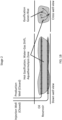
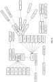
- FIG. 1A to FIG. 1C illustrate an exemplary embodiment of the present invention for treating an oil reservoir in which oil and water within the reservoir are converted to synthesis gas.
- the technology is using an inverted Steam-Assisted Gravity Drainage well configuration.
- the exemplary embodiment in FIG. 1A to FIG. 1C includes three stages per cycle.
- Stage 1 FIG. 1A
- oxygen is injected into the reservoir where a portion of the bitumen is combusted to generate the temperatures (for example, >700°C) required for the gasification, water-gas shift, and/or aquathermolysis reactions.
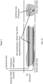
- Stage 2 FIG. 1B
- oxygen injection is stopped and the remaining oxygen in the reservoir is consumed. Since the reservoir in the near well region is hot, gasification, water-gas shift, and aquathermolysis reactions continue. The gas products from the reactions accumulate in the reservoir.
- Stage 3 FIG.
- Stage 1C is initiated, when the production well is opened which then produces synthesis gas to surface. After the synthesis gas production has dropped to non-commercial rates, the process may be re-started with Stage 1.
- the method is not limited to horizontal wells but also can be done with vertical and deviated and multilateral wells. The method can be equally applied in a gas reservoir. The injection of an oxidizing agent can continue even during production of the synthesis gas, as illustrated in FIG. 4 .
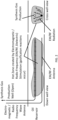
- FIG. 2 Another embodiment of the method is shown in FIG. 2 .
- heat provided to the reservoir is done by using electromagnetic / radio frequency antenna.
- the hot reservoir undergoes gasification, water-gas shift, and aquathermolysis reactions which generate hydrogen, carbon oxides, and other gases within the reservoir.
- the generated synthesis gas is produced to the surface through the production well.
- the method is not limited to horizontal wells but also can be done with vertical and deviated and multilateral wells. The method can be equally applied in a gas reservoir.
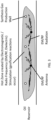
- FIG. 3 Another embodiment is illustrated in FIG. 3 , shown in the cross-well direction, illustrates electromagnetic/radio frequency heaters positioned between a plurality of hydrogen production wells.
- the method is not limited to horizontal wells but also can be done with vertical and deviated and multilateral wells. The method can be equally applied in a gas reservoir.
- the reactions generate gas which then enables gravity drainage (due to density difference) of hot mobilized oil and steam condensate towards the base of the gasification reaction chamber.
- the process sustains itself by moving mobilized oil towards the reactive zone above and around the injection well. This helps with gasification reactions and maintains the high temperature (for example 700+°C) zone near the well pair.
- a single well can be used where oxygen is injected along one part of the well and synthesis gas production occurs along another part of the well.
- the well can be vertical, deviated, or horizontal.
- heating of the reservoir can be done by electromagnetic or radio frequency waves.
- heating of the reservoir can be done by using high pressure, high temperature steam.
- the exemplary methods in a first step heat the reservoir to a temperature where gasification and/or water-gas shift reactions can take place between the oil and water within the reservoir.
- the heat can be delivered to the reservoir through a variety of methods commonly known in the art.
- Commercially available methods include oxygen injection, and in some exemplary methods the combustion step has oxygen injected into the reservoir for a period of time where a fraction of the petroleum is combusted to generate heat within the reservoir to achieve temperatures on the order of 400-700°C.
- Other modes of heating known in the art include electromagnetic or radio frequency based heating.
- Other modes of heating include injecting hot materials into the reservoir.
- oxygen injection may be stopped and the reservoir left to soak at the elevated temperature achieved by the combustion step. If heated by electromagnetic heating, then this heating can continue to keep the reservoir hot at the desired temperature.
- gasification and water-gas shift and aquathermolysis reactions may occur with consequent generation of hydrogen, hydrogen sulphide, carbon monoxide, carbon dioxide, and steam (water vapour).
- the gas components collect within the reservoir space.
- FIG. 6 illustrates some of the reactions that may occur in the reservoir.
- fuel for oxidation and gasification is the bitumen and coke that forms from reactions that occur during the process.
- Bitumen can be represented as a mixture of maltenes (saturates, aromatics, and resins) and asphaltenes (large cyclic compounds with large viscosity).
- maltenes can be converted into asphaltenes.
- Asphaltenes can be converted, via both low and high temperature oxidation as well as thermal cracking, into a variety of gas products including methane, hydrogen, carbon monoxide, carbon dioxide, hydrogen sulphide, and high molecular weight gases (e.g., propane, etc.) and coke.
- the coke can then be converted, through oxidation and gasification reactions, to products including but not limited to methane, water (vapour), carbon monoxide, carbon dioxide, and hydrogen.
- methane can be converted, via gasification reactions, to hydrogen and carbon dioxide and carbon monoxide.
- Carbon monoxide and water (vapour) can be converted, via the water-gas shift reaction, to hydrogen and carbon dioxide.
- fuel components in the system e.g., oil, coke, methane, can be gasified to produce mixtures of carbon monoxide, carbon dioxide, hydrogen sulphide, and hydrogen.
- oil accumulated in the vicinity of the lower oxygen injection well may be produced through the same oxygen injection well, or a separate well, and sold commercially, at the same time that synthesis gas is produced through the upper injection well.
- This oil can be produced either continuously, or at the same time as the synthesis gas production, or oxygen ports can inject oxygen from within the same well that oil is continuously or intermittently produced from. It may be advantageous to alter the production approach depending on properties such as the synthesis gas chamber evolution, oil mobility, reservoir pressure, or other factors.
- combustion-gas expansion lift effects controlled creation of some synthesis gas within the rising oil column drives fluid to surface like a geyser and creates simultaneous high volume vacuum/siphon
- sand isolation or expulsion from the well within the reservoir or to surface by related pressure and mobilization effects and heating of the oil/emulsion as it rises to surface.
- Some of the hydrogen may come from water which is co-produced with the oil. This can be done by adding small amounts of the down-going oxygen to the rising fluids at pyrophoric concentration/temperature conditions.
- synthesis gas components may be separated through a wide variety of well-known processes including cryogenic distillation, pressure-swing absorption/adsorption, temperature-swing absorption/adsorption, membranes, molecular sieves, centrifuges, magnetic fields, gravity/buoyancy stratification/distillation, chemical reactions, thermal break-down, resonant fields, irradiation, electrical fields, acoustical destruction, acoustical segregation, and other methods.
- Steps A to C are repeated. If continuous heating is done by oxidization agent injection or electromagnetic or radio frequency or resistive heating methods, then continuous synthesis gas production can occur from the reservoir.
- FIG. 5 illustrates an implementation of the present methods for treating an oil reservoir in which oil and water within the reservoir are converted to synthesis gas.
- Some exemplary methods heat the reservoir to a temperature where gasification and water-gas shift reactions take place involving the oil and/or water within the reservoir by continuously injecting oxygen into the reservoir (as shown in FIG. 4 ) to cause in situ combustion reactions to occur that heat the reservoir to the preferred temperature between 400 and 700°C.
- This temperature range may be transiently reached or exceeded at interstitial scale or within regions of a reservoir and does not necessitate the entire average reservoir temperature to be within this range.
- the gas components collect within the reservoir space but tend to rise due to buoyancy effects in the reservoir where the mobilized oil collects around the injection well sustaining the reactions there and the gases rise upwards towards the production well above and collect in the reservoir.
- the synthesis gas is produced from the reservoir through the production well.
- the reactive zone is characterized by the zone with temperature that is higher than the original reservoir temperature.
- the temperature rises above 450°C and at the reaction front, the temperature can exceed 900°C.
- gasification reactions occur within the hot zone which generate hydrogen which is exclusively produced by the upper production well to the surface.
- heated oil drains and accumulates around the injection well thus supplying more fuel for the reactions that occur around the injection well.
- the synthesis gas generated from the methods taught here can be used to generate power, heat, combusted to produce steam which can be used to generate power, or steam for other in situ oil recovery processes, or as a feedstock material for producing other chemicals including fuel, plastic, methanol, urea, hydrogen, sulphur, etc.
- a component e.g. a circuit, module, assembly, device, etc.
- reference to that component should be interpreted as including as equivalents of that component any component which performs the function of the described component (i.e., that is functionally equivalent), including components which are not structurally equivalent to the disclosed structure which performs the function in the illustrated exemplary embodiments of the invention.
Landscapes
- Chemical & Material Sciences (AREA)
- Engineering & Computer Science (AREA)
- Life Sciences & Earth Sciences (AREA)
- Geology (AREA)
- Mining & Mineral Resources (AREA)
- Organic Chemistry (AREA)
- General Life Sciences & Earth Sciences (AREA)
- Environmental & Geological Engineering (AREA)
- Fluid Mechanics (AREA)
- Geochemistry & Mineralogy (AREA)
- Physics & Mathematics (AREA)
- General Health & Medical Sciences (AREA)
- Chemical Kinetics & Catalysis (AREA)
- Health & Medical Sciences (AREA)
- Combustion & Propulsion (AREA)
- Inorganic Chemistry (AREA)
- Materials Engineering (AREA)
- Oil, Petroleum & Natural Gas (AREA)
- Production Of Liquid Hydrocarbon Mixture For Refining Petroleum (AREA)
- Organic Low-Molecular-Weight Compounds And Preparation Thereof (AREA)
- Hydrogen, Water And Hydrids (AREA)
- Industrial Gases (AREA)
- Low-Molecular Organic Synthesis Reactions Using Catalysts (AREA)
Claims (9)
- Verfahren zur Behandlung eines Erdölreservoirs zur Gewinnung von Synthesegas und mobilisiertem Erdöl daraus, wobei das Reservoir Erdöl und Wasser enthält, wobei das Verfahren die Schritte umfasst:a. Bereitstellen wenigstens einer Förderbohrung in dem Reservoir, wobei die wenigstens eine Förderbohrung in einem oberen Teil des Reservoirs angeordnet ist;b. Bereitstellen wenigstens einer Heizbohrung in dem Reservoir unterhalb der wenigstens einen Förderbohrung zum Behandeln eines unteren Teils des Reservoirs mit Wärme;c. unter Verwendung der Wärme Erhitzen eines Teils des Reservoirs direkt unterhalb der wenigstens einen Förderbohrung auf eine Temperatur, die ausreicht, um das Erfolgen wenigstens einer von Vergasungs-, Wasser-Gas-Shift- und Aquathermolysereaktionen innerhalb des Teils des Reservoirs zu bewirken, wobei bei der wenigstens einen der Reaktionen wenigstens eines von dem Erdöl und dem Wasser beteiligt ist;d. Ermöglichen, dass die wenigstens eine von Vergasungs-, Wasser-Gas-Shift- und Aquathermolysereaktionen Synthesegas aus dem wenigstens einen von Erdöl und dem Wasser in dem Teil des Reservoirs erzeugt, wobei das Synthesegas Wasserstoffgas umfasst, und Mobilisieren eines Teils des Erdöls, um das mobilisierte Erdöl zu bilden;e. Ermöglichen, dass das Synthesegas in Richtung zu der wenigstens einen Förderbohrung ansteigt, während sich das mobilisierte Erdöl in dem Teil des Reservoirs sammelt;f. Fördern wenigstens eines Teils des Synthesegases durch die wenigstens eine Förderbohrung an die Oberfläche; gekennzeichnet durchg. Betreiben der wenigstens einen Heizbohrung als wenigstens eine zusätzliche Förderbohrung, um einen Teil des mobilisierten Erdöls durch die wenigstens eine zusätzliche Förderbohrung gleichzeitig mit der Förderung des Teils des Synthesegases durch die wenigstens eine Förderbohrung an die Oberfläche zu fördern.
- Verfahren nach Anspruch 1, wobei der Schritt der Behandlung des unteren Teils des Reservoirs mit der Wärme Einspritzen eines Oxidationsmittels durch die wenigstens eine Heizbohrung in das Reservoir umfasst, um wenigstens einen Teil des Erdöls zu oxidieren und dadurch den Teil des Reservoirs zu erhitzen.
- Verfahren nach Anspruch 1, wobei der Schritt der Behandlung des unteren Teils des Reservoirs mit der Wärme Anordnen einer elektromagnetischen oder Radiofrequenzantenne in der wenigstens einen Heizbohrung und dadurch das Erzeugen von elektromagnetischen oder Radiofrequenzwellen und dadurch Erhitzen des Teils des Reservoirs umfasst.
- Verfahren nach Anspruch 1, wobei der Schritt der Behandlung des unteren Teils des Reservoirs mit der Wärme Anordnen eines Heizsystems auf Widerstandsbasis in der wenigstens einen Heizbohrung und dadurch das Erhitzen des Teils des Reservoirs umfasst.
- Verfahren nach Anspruch 1, wobei Schritt d. für einen Zeitraum von einer Woche bis zwölf Monaten stattfindet.
- Verfahren nach Anspruch 2, wobei wenigstens eines von Wasser, Dampf, brennbaren Brennstoffen und Abfallprodukten mit oder getrennt von dem Einspritzen des Oxidationsmittels eingespritzt wird.
- Verfahren nach Anspruch 1, ferner umfassend Wiederholen und Abwechseln der Schritte des Erhitzens des Teils des Reservoirs und Förderns des Teils des Synthesegases an die Oberfläche.
- System zur Behandlung eines Erdölreservoirs zur Gewinnung von Synthesegas und mobilisiertem Erdöl daraus, wobei das Reservoir Erdöl und Wasser enthält, wobei das Synthesegas Wasserstoffgas umfasst, wobei das System umfasst:wenigstens eine Förderbohrung, die in einem oberen Teil des Reservoirs angeordnet ist; undwenigstens eine Heizbohrung zum Erhitzen eines Teils des Reservoirs direkt unterhalb der wenigstens einen Förderbohrung und dadurch Erzeugen des Synthesegases aus dem wenigstens einen von dem Erdöl und dem Wasser durch wenigstens eine von Vergasungs-, Wasser-Gas-Shift- und Aquathermolysereaktionen und Mobilisieren eines Teils des Erdöls, um das mobilisierte Erdöl zu bilden, wobei die wenigstens eine Heizbohrung in einem unteren Teil des Reservoirs angeordnet ist;wobei die wenigstens eine Förderbohrung dafür gestaltet ist, einen Teil des Synthesegases aufzunehmen und zu Oberfläche zu fördern, während sich das mobilisierte Erdöl in dem Teil des Reservoirs sammelt; unddie wenigstens eine Heizbohrung für den Betrieb als zusätzliche Förderbohrung gestaltet ist, um das mobilisierte Erdöl gleichzeitig mit der Förderung des Teils des Synthesegases durch die wenigstens eine Förderbohrung an die Oberfläche zu fördern.
- System nach Anspruch 8, wobei wenigstens eine Heizbohrung eine Wärmezufuhr ausgewählt aus der Gruppe bestehend aus einem Oxidationsmittelinjektor, einem Elektromagneten, einer Radiofrequenzantenne und einem Heißmaterialinjektor umfasst.
Applications Claiming Priority (2)
| Application Number | Priority Date | Filing Date | Title |
|---|---|---|---|
| US201862639184P | 2018-03-06 | 2018-03-06 | |
| PCT/CA2019/050271 WO2019169492A1 (en) | 2018-03-06 | 2019-03-06 | In-situ process to produce synthesis gas from underground hydrocarbon reservoirs |
Publications (4)
| Publication Number | Publication Date |
|---|---|
| EP3762583A1 EP3762583A1 (de) | 2021-01-13 |
| EP3762583A4 EP3762583A4 (de) | 2021-12-22 |
| EP3762583B1 true EP3762583B1 (de) | 2025-01-01 |
| EP3762583C0 EP3762583C0 (de) | 2025-01-01 |
Family
ID=67846441
Family Applications (1)
| Application Number | Title | Priority Date | Filing Date |
|---|---|---|---|
| EP19764420.6A Active EP3762583B1 (de) | 2018-03-06 | 2019-03-06 | In-situ-verfahren zur erzeugung von synthesegas aus unterirdischen kohlenwasserstoffreservoirs |
Country Status (21)
| Country | Link |
|---|---|
| US (1) | US20210047905A1 (de) |
| EP (1) | EP3762583B1 (de) |
| JP (1) | JP2021515860A (de) |
| CN (1) | CN112088242A (de) |
| AU (1) | AU2019231362B2 (de) |
| CA (1) | CA3092890A1 (de) |
| CL (1) | CL2020002295A1 (de) |
| CO (1) | CO2020012424A2 (de) |
| CU (1) | CU24745B1 (de) |
| EA (1) | EA202091947A1 (de) |
| EC (1) | ECSP20062568A (de) |
| IL (1) | IL277145A (de) |
| JO (1) | JOP20200219A1 (de) |
| MA (1) | MA51177B1 (de) |
| MX (1) | MX2020009291A (de) |
| MY (1) | MY210513A (de) |
| PE (1) | PE20220610A1 (de) |
| PH (1) | PH12020551480A1 (de) |
| TN (1) | TN2020000184A1 (de) |
| WO (1) | WO2019169492A1 (de) |
| ZA (1) | ZA202006127B (de) |
Families Citing this family (13)
| Publication number | Priority date | Publication date | Assignee | Title |
|---|---|---|---|---|
| MA61699A1 (fr) * | 2020-12-18 | 2023-09-27 | Proton Tech Inc | Procédés de réorientation d'opérations de récupération thermique d'hydrocarbures pour la production de gaz de synthèse |
| CN112324409B (zh) * | 2020-12-31 | 2021-07-06 | 西南石油大学 | 一种在油层中原位产生溶剂开采稠油的方法 |
| WO2023044149A1 (en) * | 2021-09-20 | 2023-03-23 | Texas Tech University System | In-situ hydrogen generation and production from petroleum reservoirs |
| CN114215601B (zh) * | 2021-12-31 | 2024-01-26 | 北京派创石油技术服务有限公司 | 利用废弃油井制造氢气的方法 |
| US11828147B2 (en) | 2022-03-30 | 2023-11-28 | Hunt Energy, L.L.C. | System and method for enhanced geothermal energy extraction |
| DE102022203221B3 (de) | 2022-03-31 | 2023-07-06 | Technische Universität Bergakademie Freiberg, Körperschaft des öffentlichen Rechts | Verfahren und anlage zur gewinnung von wasserstoff aus einem kohlenwasserstoffreservoir |
| DE102022203277B3 (de) | 2022-04-01 | 2023-07-13 | Technische Universität Bergakademie Freiberg, Körperschaft des öffentlichen Rechts | Verfahren und anlage zur gewinnung von wasserstoff aus einem kohlenwasserstoffreservoir |
| CN115853479A (zh) * | 2022-12-29 | 2023-03-28 | 西南石油大学 | 一种基于低渗水侵气藏的制氢方法 |
| CN115929269A (zh) * | 2022-12-30 | 2023-04-07 | 西安石油大学 | 一种稠油油藏气化驱采油方法 |
| US12264564B1 (en) | 2023-11-22 | 2025-04-01 | ProtonH2 Analytics, Limited | In-situ process to produce hydrogen-bearing gas from underground petroleum reservoirs |
| WO2025172302A1 (en) | 2024-02-12 | 2025-08-21 | Vedra Hydrogen Limited | A process for producing hydrogen gas from a subterranean light oil reservoir |
| WO2025185840A1 (en) | 2024-03-06 | 2025-09-12 | ProtonH2 Analytics, Limited | Treatment of previously-produced petroleum reservoirs for production of hydrogen |
| WO2025215254A1 (en) | 2024-04-12 | 2025-10-16 | ProtonH2 Analytics, Limited | Treatment of underground formations for production of hydrogen |
Family Cites Families (22)
| Publication number | Priority date | Publication date | Assignee | Title |
|---|---|---|---|---|
| US4330038A (en) * | 1980-05-14 | 1982-05-18 | Zimpro-Aec Ltd. | Oil reclamation process |
| US4427066A (en) * | 1981-05-08 | 1984-01-24 | Mobil Oil Corporation | Oil recovery method |
| US4597441A (en) * | 1984-05-25 | 1986-07-01 | World Energy Systems, Inc. | Recovery of oil by in situ hydrogenation |
| US4691771A (en) * | 1984-09-25 | 1987-09-08 | Worldenergy Systems, Inc. | Recovery of oil by in-situ combustion followed by in-situ hydrogenation |
| GB0009662D0 (en) * | 2000-04-20 | 2000-06-07 | Scotoil Group Plc | Gas and oil production |
| GB2391891B (en) * | 2000-04-24 | 2004-09-29 | Shell Int Research | In situ recovery from a hydrocarbon containing formation |
| NZ535558A (en) * | 2000-04-24 | 2006-11-30 | Shell Int Research | In situ recovery from a hydrocarbon containing formation |
| CN1267621C (zh) * | 2000-04-24 | 2006-08-02 | 国际壳牌研究有限公司 | 处理含烃岩层的方法及生产烃类和能源的方法 |
| US6991032B2 (en) * | 2001-04-24 | 2006-01-31 | Shell Oil Company | In situ thermal processing of an oil shale formation using a pattern of heat sources |
| US20030079877A1 (en) * | 2001-04-24 | 2003-05-01 | Wellington Scott Lee | In situ thermal processing of a relatively impermeable formation in a reducing environment |
| CN1575375A (zh) * | 2001-10-24 | 2005-02-02 | 国际壳牌研究有限公司 | 煤的原地升级 |
| US20050239661A1 (en) * | 2004-04-21 | 2005-10-27 | Pfefferle William C | Downhole catalytic combustion for hydrogen generation and heavy oil mobility enhancement |
| US7467660B2 (en) * | 2005-03-31 | 2008-12-23 | Hce, Llc | Pumped carbon mining methane production process |
| CA2663823C (en) * | 2006-10-13 | 2014-09-30 | Exxonmobil Upstream Research Company | Enhanced shale oil production by in situ heating using hydraulically fractured producing wells |
| US7836957B2 (en) * | 2007-09-11 | 2010-11-23 | Singleton Alan H | In situ conversion of subsurface hydrocarbon deposits to synthesis gas |
| US8151907B2 (en) * | 2008-04-18 | 2012-04-10 | Shell Oil Company | Dual motor systems and non-rotating sensors for use in developing wellbores in subsurface formations |
| JP2012514148A (ja) * | 2008-12-31 | 2012-06-21 | シェブロン ユー.エス.エー. インコーポレイテッド | 利用可能な廃熱を用いてハイドレート貯留層から炭化水素を生産する方法及びシステム |
| CA2698454C (en) * | 2010-03-30 | 2011-11-29 | Archon Technologies Ltd. | Improved in-situ combustion recovery process using single horizontal well to produce oil and combustion gases to surface |
| US8616273B2 (en) * | 2010-11-17 | 2013-12-31 | Harris Corporation | Effective solvent extraction system incorporating electromagnetic heating |
| CA2884849C (en) * | 2015-03-11 | 2017-10-24 | Suncor Energy Inc. | In-situ upgrading and recovery of hydrocarbons |
| US9982205B2 (en) * | 2015-08-03 | 2018-05-29 | Craig Pichach | Subterranean gasification system and method |
| GEP20227341B (en) * | 2016-02-08 | 2022-01-25 | Proton Tech Inc | In-situ process to produce hydrogen from underground hydrocarbon reservoirs |
-
2019
- 2019-03-06 MX MX2020009291A patent/MX2020009291A/es unknown
- 2019-03-06 PE PE2020001358A patent/PE20220610A1/es unknown
- 2019-03-06 EP EP19764420.6A patent/EP3762583B1/de active Active
- 2019-03-06 MA MA51177A patent/MA51177B1/fr unknown
- 2019-03-06 WO PCT/CA2019/050271 patent/WO2019169492A1/en not_active Ceased
- 2019-03-06 EA EA202091947A patent/EA202091947A1/ru unknown
- 2019-03-06 MY MYPI2020004599A patent/MY210513A/en unknown
- 2019-03-06 CA CA3092890A patent/CA3092890A1/en active Pending
- 2019-03-06 CU CU2020000065A patent/CU24745B1/es unknown
- 2019-03-06 CN CN201980030609.4A patent/CN112088242A/zh active Pending
- 2019-03-06 TN TNP/2020/000184A patent/TN2020000184A1/en unknown
- 2019-03-06 JP JP2020570604A patent/JP2021515860A/ja active Pending
- 2019-03-06 US US16/978,860 patent/US20210047905A1/en not_active Abandoned
- 2019-03-06 JO JOP/2020/0219A patent/JOP20200219A1/ar unknown
- 2019-03-06 AU AU2019231362A patent/AU2019231362B2/en active Active
-
2020
- 2020-09-04 PH PH12020551480A patent/PH12020551480A1/en unknown
- 2020-09-04 CL CL2020002295A patent/CL2020002295A1/es unknown
- 2020-09-06 IL IL277145A patent/IL277145A/en unknown
- 2020-10-02 EC ECSENADI202062568A patent/ECSP20062568A/es unknown
- 2020-10-02 CO CONC2020/0012424A patent/CO2020012424A2/es unknown
- 2020-10-02 ZA ZA2020/06127A patent/ZA202006127B/en unknown
Also Published As
| Publication number | Publication date |
|---|---|
| US20210047905A1 (en) | 2021-02-18 |
| ECSP20062568A (es) | 2020-12-31 |
| PE20220610A1 (es) | 2022-04-26 |
| BR112020018160A2 (pt) | 2021-02-02 |
| MX2020009291A (es) | 2020-12-11 |
| EP3762583A1 (de) | 2021-01-13 |
| CU24745B1 (es) | 2025-04-04 |
| MA51177B1 (fr) | 2021-08-31 |
| CO2020012424A2 (es) | 2020-10-30 |
| CL2020002295A1 (es) | 2021-02-19 |
| MY210513A (en) | 2025-09-28 |
| IL277145A (en) | 2020-10-29 |
| EP3762583C0 (de) | 2025-01-01 |
| ZA202006127B (en) | 2024-02-28 |
| MA51177A1 (fr) | 2021-02-26 |
| CU20200065A7 (es) | 2021-04-07 |
| WO2019169492A1 (en) | 2019-09-12 |
| AU2019231362A1 (en) | 2020-10-01 |
| JOP20200219A1 (ar) | 2020-09-06 |
| TN2020000184A1 (en) | 2022-04-04 |
| EP3762583A4 (de) | 2021-12-22 |
| AU2019231362B2 (en) | 2025-03-27 |
| PH12020551480A1 (en) | 2021-09-06 |
| EA202091947A1 (ru) | 2021-01-11 |
| CN112088242A (zh) | 2020-12-15 |
| JP2021515860A (ja) | 2021-06-24 |
| CA3092890A1 (en) | 2019-09-12 |
Similar Documents
| Publication | Publication Date | Title |
|---|---|---|
| EP3762583B1 (de) | In-situ-verfahren zur erzeugung von synthesegas aus unterirdischen kohlenwasserstoffreservoirs | |
| JP6983166B2 (ja) | 地下炭化水素貯留層からの水素のその場生産方法 | |
| RU2487236C2 (ru) | Способ обработки подземного пласта (варианты) и моторное топливо, полученное с использованием способа | |
| CA2665865C (en) | Heating hydrocarbon containing formations in a spiral startup staged sequence | |
| US6328104B1 (en) | Upgrading and recovery of heavy crude oils and natural bitumens by in situ hydrovisbreaking | |
| EP1276964B1 (de) | Verfahren zur behandlung von erdöllagerstätten | |
| EA015915B1 (ru) | Регулирование и оценивание режима давления при обработке пластов битуминозных песков | |
| AU2001260241A1 (en) | A method for treating a hydrocarbon containing formation | |
| Xia et al. | 3-D physical model studies of downhole catalytic upgrading of Wolf Lake heavy oil using THAI | |
| US9534482B2 (en) | Thermal mobilization of heavy hydrocarbon deposits | |
| OA20214A (en) | In-situ process to produce synthesis gas from underground hydrocarbon reservoirs. | |
| EA044304B1 (ru) | Процесс добычи синтез-газа на месте из подземных углеводородных пластов | |
| BR112020018160B1 (pt) | Método para tratar um reservatório de petróleo contendo petróleo e água para gerar e recuperar gás de síntese e petróleo mobilizado do mesmo | |
| OA18941A (en) | In-situ process to produce hydrogen from underground hydrocarbon reservoirs |
Legal Events
| Date | Code | Title | Description |
|---|---|---|---|
| STAA | Information on the status of an ep patent application or granted ep patent |
Free format text: STATUS: THE INTERNATIONAL PUBLICATION HAS BEEN MADE |
|
| PUAI | Public reference made under article 153(3) epc to a published international application that has entered the european phase |
Free format text: ORIGINAL CODE: 0009012 |
|
| STAA | Information on the status of an ep patent application or granted ep patent |
Free format text: STATUS: REQUEST FOR EXAMINATION WAS MADE |
|
| 17P | Request for examination filed |
Effective date: 20200922 |
|
| AK | Designated contracting states |
Kind code of ref document: A1 Designated state(s): AL AT BE BG CH CY CZ DE DK EE ES FI FR GB GR HR HU IE IS IT LI LT LU LV MC MK MT NL NO PL PT RO RS SE SI SK SM TR |
|
| AX | Request for extension of the european patent |
Extension state: BA ME |
|
| RAP3 | Party data changed (applicant data changed or rights of an application transferred) |
Owner name: PROTON TECHNOLOGIES CANADA INC. |
|
| DAV | Request for validation of the european patent (deleted) | ||
| DAX | Request for extension of the european patent (deleted) | ||
| A4 | Supplementary search report drawn up and despatched |
Effective date: 20211123 |
|
| RIC1 | Information provided on ipc code assigned before grant |
Ipc: E21B 43/243 20060101ALI20211117BHEP Ipc: E21B 43/24 20060101ALI20211117BHEP Ipc: E21B 43/295 20060101AFI20211117BHEP |
|
| STAA | Information on the status of an ep patent application or granted ep patent |
Free format text: STATUS: EXAMINATION IS IN PROGRESS |
|
| 17Q | First examination report despatched |
Effective date: 20230517 |
|
| GRAP | Despatch of communication of intention to grant a patent |
Free format text: ORIGINAL CODE: EPIDOSNIGR1 |
|
| STAA | Information on the status of an ep patent application or granted ep patent |
Free format text: STATUS: GRANT OF PATENT IS INTENDED |
|
| INTG | Intention to grant announced |
Effective date: 20240828 |
|
| GRAS | Grant fee paid |
Free format text: ORIGINAL CODE: EPIDOSNIGR3 |
|
| GRAA | (expected) grant |
Free format text: ORIGINAL CODE: 0009210 |
|
| STAA | Information on the status of an ep patent application or granted ep patent |
Free format text: STATUS: THE PATENT HAS BEEN GRANTED |
|
| AK | Designated contracting states |
Kind code of ref document: B1 Designated state(s): AL AT BE BG CH CY CZ DE DK EE ES FI FR GB GR HR HU IE IS IT LI LT LU LV MC MK MT NL NO PL PT RO RS SE SI SK SM TR |
|
| REG | Reference to a national code |
Ref country code: GB Ref legal event code: FG4D |
|
| REG | Reference to a national code |
Ref country code: CH Ref legal event code: EP |
|
| REG | Reference to a national code |
Ref country code: DE Ref legal event code: R096 Ref document number: 602019064279 Country of ref document: DE |
|
| REG | Reference to a national code |
Ref country code: IE Ref legal event code: FG4D |
|
| U01 | Request for unitary effect filed |
Effective date: 20250110 |
|
| U07 | Unitary effect registered |
Designated state(s): AT BE BG DE DK EE FI FR IT LT LU LV MT NL PT RO SE SI Effective date: 20250117 |
|
| U20 | Renewal fee for the european patent with unitary effect paid |
Year of fee payment: 7 Effective date: 20250317 |
|
| PG25 | Lapsed in a contracting state [announced via postgrant information from national office to epo] |
Ref country code: PL Free format text: LAPSE BECAUSE OF FAILURE TO SUBMIT A TRANSLATION OF THE DESCRIPTION OR TO PAY THE FEE WITHIN THE PRESCRIBED TIME-LIMIT Effective date: 20250101 |
|
| PG25 | Lapsed in a contracting state [announced via postgrant information from national office to epo] |
Ref country code: ES Free format text: LAPSE BECAUSE OF FAILURE TO SUBMIT A TRANSLATION OF THE DESCRIPTION OR TO PAY THE FEE WITHIN THE PRESCRIBED TIME-LIMIT Effective date: 20250101 |
|
| PG25 | Lapsed in a contracting state [announced via postgrant information from national office to epo] |
Ref country code: IS Free format text: LAPSE BECAUSE OF FAILURE TO SUBMIT A TRANSLATION OF THE DESCRIPTION OR TO PAY THE FEE WITHIN THE PRESCRIBED TIME-LIMIT Effective date: 20250501 |
|
| PG25 | Lapsed in a contracting state [announced via postgrant information from national office to epo] |
Ref country code: HR Free format text: LAPSE BECAUSE OF FAILURE TO SUBMIT A TRANSLATION OF THE DESCRIPTION OR TO PAY THE FEE WITHIN THE PRESCRIBED TIME-LIMIT Effective date: 20250101 |
|
| PG25 | Lapsed in a contracting state [announced via postgrant information from national office to epo] |
Ref country code: GR Free format text: LAPSE BECAUSE OF FAILURE TO SUBMIT A TRANSLATION OF THE DESCRIPTION OR TO PAY THE FEE WITHIN THE PRESCRIBED TIME-LIMIT Effective date: 20250402 |
|
| PG25 | Lapsed in a contracting state [announced via postgrant information from national office to epo] |
Ref country code: CZ Free format text: LAPSE BECAUSE OF FAILURE TO SUBMIT A TRANSLATION OF THE DESCRIPTION OR TO PAY THE FEE WITHIN THE PRESCRIBED TIME-LIMIT Effective date: 20250101 |
|
| PG25 | Lapsed in a contracting state [announced via postgrant information from national office to epo] |
Ref country code: SM Free format text: LAPSE BECAUSE OF FAILURE TO SUBMIT A TRANSLATION OF THE DESCRIPTION OR TO PAY THE FEE WITHIN THE PRESCRIBED TIME-LIMIT Effective date: 20250101 |
|
| PG25 | Lapsed in a contracting state [announced via postgrant information from national office to epo] |
Ref country code: MC Free format text: LAPSE BECAUSE OF FAILURE TO SUBMIT A TRANSLATION OF THE DESCRIPTION OR TO PAY THE FEE WITHIN THE PRESCRIBED TIME-LIMIT Effective date: 20250101 |
|
| REG | Reference to a national code |
Ref country code: CH Ref legal event code: H13 Free format text: ST27 STATUS EVENT CODE: U-0-0-H10-H13 (AS PROVIDED BY THE NATIONAL OFFICE) Effective date: 20251023 |
|
| PG25 | Lapsed in a contracting state [announced via postgrant information from national office to epo] |
Ref country code: SK Free format text: LAPSE BECAUSE OF FAILURE TO SUBMIT A TRANSLATION OF THE DESCRIPTION OR TO PAY THE FEE WITHIN THE PRESCRIBED TIME-LIMIT Effective date: 20250101 |
|
| PLBE | No opposition filed within time limit |
Free format text: ORIGINAL CODE: 0009261 |
|
| STAA | Information on the status of an ep patent application or granted ep patent |
Free format text: STATUS: NO OPPOSITION FILED WITHIN TIME LIMIT |
|
| 26N | No opposition filed |
Effective date: 20251002 |
|
| PG25 | Lapsed in a contracting state [announced via postgrant information from national office to epo] |
Ref country code: CH Free format text: LAPSE BECAUSE OF NON-PAYMENT OF DUE FEES Effective date: 20250331 |
|
| PG25 | Lapsed in a contracting state [announced via postgrant information from national office to epo] |
Ref country code: IE Free format text: LAPSE BECAUSE OF NON-PAYMENT OF DUE FEES Effective date: 20250306 |
|
| PGFP | Annual fee paid to national office [announced via postgrant information from national office to epo] |
Ref country code: GB Payment date: 20260318 Year of fee payment: 8 |
|
| PGFP | Annual fee paid to national office [announced via postgrant information from national office to epo] |
Ref country code: NO Payment date: 20260318 Year of fee payment: 8 |
|
| U20 | Renewal fee for the european patent with unitary effect paid |
Year of fee payment: 8 Effective date: 20260318 |