EP3761885B1 - Systeme und verfahren zur fernsteuerung eines chirurgischen instruments von konsolenbasierten chirurgischen systemen - Google Patents
Systeme und verfahren zur fernsteuerung eines chirurgischen instruments von konsolenbasierten chirurgischen systemen Download PDFInfo
- Publication number
- EP3761885B1 EP3761885B1 EP19713261.6A EP19713261A EP3761885B1 EP 3761885 B1 EP3761885 B1 EP 3761885B1 EP 19713261 A EP19713261 A EP 19713261A EP 3761885 B1 EP3761885 B1 EP 3761885B1
- Authority
- EP
- European Patent Office
- Prior art keywords
- dongle
- surgical
- control device
- control
- console
- Prior art date
- Legal status (The legal status is an assumption and is not a legal conclusion. Google has not performed a legal analysis and makes no representation as to the accuracy of the status listed.)
- Active
Links
Images


Classifications
-
- H—ELECTRICITY
- H04—ELECTRIC COMMUNICATION TECHNIQUE
- H04W—WIRELESS COMMUNICATION NETWORKS
- H04W76/00—Connection management
- H04W76/10—Connection setup
- H04W76/14—Direct-mode setup
-
- A—HUMAN NECESSITIES
- A61—MEDICAL OR VETERINARY SCIENCE; HYGIENE
- A61B—DIAGNOSIS; SURGERY; IDENTIFICATION
- A61B17/00—Surgical instruments, devices or methods
-
- A—HUMAN NECESSITIES
- A61—MEDICAL OR VETERINARY SCIENCE; HYGIENE
- A61B—DIAGNOSIS; SURGERY; IDENTIFICATION
- A61B18/00—Surgical instruments, devices or methods for transferring non-mechanical forms of energy to or from the body
-
- A—HUMAN NECESSITIES
- A61—MEDICAL OR VETERINARY SCIENCE; HYGIENE
- A61B—DIAGNOSIS; SURGERY; IDENTIFICATION
- A61B90/00—Instruments, implements or accessories specially adapted for surgery or diagnosis and not covered by any of the groups A61B1/00 - A61B50/00, e.g. for luxation treatment or for protecting wound edges
- A61B90/90—Identification means for patients or instruments, e.g. tags
- A61B90/98—Identification means for patients or instruments, e.g. tags using electromagnetic means, e.g. transponders
-
- G—PHYSICS
- G16—INFORMATION AND COMMUNICATION TECHNOLOGY [ICT] SPECIALLY ADAPTED FOR SPECIFIC APPLICATION FIELDS
- G16H—HEALTHCARE INFORMATICS, i.e. INFORMATION AND COMMUNICATION TECHNOLOGY [ICT] SPECIALLY ADAPTED FOR THE HANDLING OR PROCESSING OF MEDICAL OR HEALTHCARE DATA
- G16H40/00—ICT specially adapted for the management or administration of healthcare resources or facilities; ICT specially adapted for the management or operation of medical equipment or devices
- G16H40/60—ICT specially adapted for the management or administration of healthcare resources or facilities; ICT specially adapted for the management or operation of medical equipment or devices for the operation of medical equipment or devices
- G16H40/63—ICT specially adapted for the management or administration of healthcare resources or facilities; ICT specially adapted for the management or operation of medical equipment or devices for the operation of medical equipment or devices for local operation
-
- G—PHYSICS
- G16—INFORMATION AND COMMUNICATION TECHNOLOGY [ICT] SPECIALLY ADAPTED FOR SPECIFIC APPLICATION FIELDS
- G16H—HEALTHCARE INFORMATICS, i.e. INFORMATION AND COMMUNICATION TECHNOLOGY [ICT] SPECIALLY ADAPTED FOR THE HANDLING OR PROCESSING OF MEDICAL OR HEALTHCARE DATA
- G16H40/00—ICT specially adapted for the management or administration of healthcare resources or facilities; ICT specially adapted for the management or operation of medical equipment or devices
- G16H40/60—ICT specially adapted for the management or administration of healthcare resources or facilities; ICT specially adapted for the management or operation of medical equipment or devices for the operation of medical equipment or devices
- G16H40/67—ICT specially adapted for the management or administration of healthcare resources or facilities; ICT specially adapted for the management or operation of medical equipment or devices for the operation of medical equipment or devices for remote operation
-
- H—ELECTRICITY
- H04—ELECTRIC COMMUNICATION TECHNIQUE
- H04W—WIRELESS COMMUNICATION NETWORKS
- H04W12/00—Security arrangements; Authentication; Protecting privacy or anonymity
- H04W12/03—Protecting confidentiality, e.g. by encryption
- H04W12/037—Protecting confidentiality, e.g. by encryption of the control plane, e.g. signalling traffic
-
- H—ELECTRICITY
- H04—ELECTRIC COMMUNICATION TECHNIQUE
- H04W—WIRELESS COMMUNICATION NETWORKS
- H04W12/00—Security arrangements; Authentication; Protecting privacy or anonymity
- H04W12/50—Secure pairing of devices
-
- A—HUMAN NECESSITIES
- A61—MEDICAL OR VETERINARY SCIENCE; HYGIENE
- A61B—DIAGNOSIS; SURGERY; IDENTIFICATION
- A61B18/00—Surgical instruments, devices or methods for transferring non-mechanical forms of energy to or from the body
- A61B18/04—Surgical instruments, devices or methods for transferring non-mechanical forms of energy to or from the body by heating
- A61B18/12—Surgical instruments, devices or methods for transferring non-mechanical forms of energy to or from the body by heating by passing a current through the tissue to be heated, e.g. high-frequency current
-
- A—HUMAN NECESSITIES
- A61—MEDICAL OR VETERINARY SCIENCE; HYGIENE
- A61B—DIAGNOSIS; SURGERY; IDENTIFICATION
- A61B17/00—Surgical instruments, devices or methods
- A61B2017/00017—Electrical control of surgical instruments
- A61B2017/00199—Electrical control of surgical instruments with a console, e.g. a control panel with a display
-
- A—HUMAN NECESSITIES
- A61—MEDICAL OR VETERINARY SCIENCE; HYGIENE
- A61B—DIAGNOSIS; SURGERY; IDENTIFICATION
- A61B17/00—Surgical instruments, devices or methods
- A61B2017/00017—Electrical control of surgical instruments
- A61B2017/00212—Electrical control of surgical instruments using remote controls
-
- A—HUMAN NECESSITIES
- A61—MEDICAL OR VETERINARY SCIENCE; HYGIENE
- A61B—DIAGNOSIS; SURGERY; IDENTIFICATION
- A61B17/00—Surgical instruments, devices or methods
- A61B2017/00017—Electrical control of surgical instruments
- A61B2017/00221—Electrical control of surgical instruments with wireless transmission of data, e.g. by infrared radiation or radiowaves
-
- A—HUMAN NECESSITIES
- A61—MEDICAL OR VETERINARY SCIENCE; HYGIENE
- A61B—DIAGNOSIS; SURGERY; IDENTIFICATION
- A61B17/00—Surgical instruments, devices or methods
- A61B2017/00477—Coupling
- A61B2017/00482—Coupling with a code
-
- A—HUMAN NECESSITIES
- A61—MEDICAL OR VETERINARY SCIENCE; HYGIENE
- A61B—DIAGNOSIS; SURGERY; IDENTIFICATION
- A61B17/00—Surgical instruments, devices or methods
- A61B2017/00973—Surgical instruments, devices or methods pedal-operated
-
- A—HUMAN NECESSITIES
- A61—MEDICAL OR VETERINARY SCIENCE; HYGIENE
- A61B—DIAGNOSIS; SURGERY; IDENTIFICATION
- A61B18/00—Surgical instruments, devices or methods for transferring non-mechanical forms of energy to or from the body
- A61B2018/00053—Mechanical features of the instrument of device
- A61B2018/00172—Connectors and adapters therefor
-
- A—HUMAN NECESSITIES
- A61—MEDICAL OR VETERINARY SCIENCE; HYGIENE
- A61B—DIAGNOSIS; SURGERY; IDENTIFICATION
- A61B18/00—Surgical instruments, devices or methods for transferring non-mechanical forms of energy to or from the body
- A61B2018/0091—Handpieces of the surgical instrument or device
- A61B2018/00916—Handpieces of the surgical instrument or device with means for switching or controlling the main function of the instrument or device
Definitions
- Console-based surgical systems include a surgical console having surgical devices and control devices (e.g., footswitches or handswitches) connected thereto.
- the surgical devices can be controlled by the control devices through the console.
- control devices are physically and directly connected to the console.
- the control device may include a hard-wired cable and a connector that plugs into the console, thereby allowing the control device to control the surgical device.
- presence of the cable clutters the operating room or causes a tripping hazard.
- cable management before, during and after any operation requires more time from healthcare personal.
- wireless devices may be hard-paired, such that one device is preconfigured to wirelessly communicate solely with a specified device, and vice-versa.
- One problem with such an approach relates to inventory.
- surgical system devices are often mixed and matched, as required by demand in the facility.
- Hard-paired devices must remain together in inventory to provide utility. If one of the devices is separated and mixed with another system, both devices become inoperable.
- US 7 846 150 B2 discloses a system for controlling one or more medical devices by a remote console.
- the remote console communicates wirelessly with a central control unit that connects to one or more of the medical devices.
- the central control unit must synchronize with the remote console and establish a secure communication link with it before the central control unit will respond to a wireless command signal transmitted by the remote console.
- US 2013/099902 A1 discloses a system and method for controlling a body-scanning device using multiple wireless devices.
- the method includes communicating a secure wireless signal from a footswitch enclosure to a footswitch receiver coupled to the body-scanning device in response to an actuation of a footswitch zone carried on the footswitch enclosure. Additionally, a wireless signal is communicated from a handswitch enclosure in response to an actuation of a handswitch zone and communicated to a handswitch receiver located in the footswitch enclosure. The wireless signal is then communicated from the footswitch enclosure to the footswitch receiver coupled to the body-scanning device to enable an operator to control the body-scanning device using the handswitch or the footswitch.
- WO 2017/009735 A1 discloses a mobile ultrasound system.
- the mobile ultrasound system will pair with a wireless ultra sound probe for exclusive communication between the two for an ultrasound exam when the wireless probe is brought to within a predetermined distance of the mobile ultrasound system.
- the ultrasound system determines that the wireless probe is within the predetermined distance from the strength of the signal received by the system from the wireless probe. Pairing can proceed automatically when a wireless probe is within the predetermined distance, or after a user actuates a control to initiate the pairing.
- the ultrasound system may display the identity of a probe within range on the display of the system for selection by the user so that the user will be confident that pairing will be done with the desired wireless probe.
- a surgical system and a method for operating a surgical system are provided according to the independent claims. Preferred embodiments are recited in the dependent claims.
- the surgical system comprises a surgical console, a control device, and a dongle.
- the surgical console operates a surgical device and comprises a connection port.
- the control device communicates with the surgical console to remotely control the surgical device.
- the dongle physically couples to the connection port of the surgical console.
- the control device comprises a first communication device and a radio frequency (RF) reader and the dongle comprises a second communication device and a passive RF device.
- the RF reader receives the pairing information from the passive RF device in response to the passive RF device being within a threshold proximity of the RF reader.
- the first and second communication devices wirelessly connect based on the pairing information, enabling the control device to wirelessly communicate with the surgical console to remotely control the surgical device.
- the surgical system comprises a surgical console configured to operate a surgical device, the surgical console comprising a connection port.
- the surgical system also comprises a control device and a dongle.
- the control device communicates with the surgical console to remotely control the surgical device, the control device comprising a first communication device and an RF reader.
- the dongle comprises a second communication device and a passive RF device.
- the method of operating the surgical system includes a step of establishing a threshold proximity between the passive RF device of the dongle and RF reader of the control device; a step of receiving, with the RF reader of the control device, pairing information from the passive RF device of the dongle in response to the passive RF device and the RF reader being within the threshold proximity; a step of physically coupling the dongle to the connection port of the surgical console; and a step of establishing a wireless connection between the first and second communication devices based on the pairing information; wherein the wireless connection is configured for remotely and wirelessly controlling the surgical device with the control device using the wireless connection.
- the surgical system comprises a surgical console, a control device, a first dongle, and a second dongle.
- the surgical console operates a surgical device and comprises a connection port.
- the control device communicates with the surgical console to remotely control the surgical device.
- the first dongle comprises a first communication device and a passive RF device and the second dongle includes a second communication device and an RF reader.
- One of the first and second dongles physically couples to the connection port of the surgical console and the other one of the first and second dongles physically couples to the connection port of the control device.
- the RF reader receives the pairing information from the passive RF device in response to the passive RF device being within a threshold proximity of the RF reader.
- the first and second communication devices wirelessly connect based on the pairing information, enabling the control device to wirelessly communicate with the surgical console to remotely control the surgical device.
- the surgical system comprises a surgical console configured to operate a surgical device, the surgical console comprising a connection port.
- the surgical system also comprises a control device configured to communicate with the surgical console to remotely control the surgical device, the control device comprising a communication device and an RF reader.
- the dongle comprises a coupling interface, a passive RF device and a communication device.
- the coupling interface physically couples the dongle to the connection port of the surgical console.
- the passive RF device is configured to transmit pairing information to the RF reader of the control device in response to the passive RF device being within a threshold proximity of the RF reader.
- the communication device of the dongle is configured to wirelessly connect to the communication device of the control device based on the pairing information to enable wireless communication between the control device and the surgical console to remotely control the surgical device.
- the surgical system comprises a surgical console and a control device.
- the surgical console operates a surgical device and comprises a connection port.
- the control device communicates with the surgical console to remotely control the surgical device and comprises a connection port.
- the communication system comprises a first dongle and a second dongle.
- the first dongle comprises a first coupling interface configured to physically couple to the connection port of one of the surgical console and the control device, an RF reader, and a first communication device.
- the second dongle comprises a second coupling interface, a passive RF device, and a second communication device.
- the second coupling interface is configured to physically couple to the connection port of the other one of the surgical console and the control device, which is not physically coupled to the first coupling interface.
- the passive RF device transmits pairing information to the RF reader of the first dongle in response to the passive RF device and the RF reader being within a threshold proximity to one another.
- the second communication device wirelessly connects to the first communication device of the first dongle based on the pairing information to thereby enable the control device to wirelessly communicate with the surgical console to remotely control the surgical device.
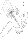
- the surgical system 100 includes a surgical console 102, which is configured to operate a surgical device 110.
- the surgical device 110 may be one of many surgical devices, such as those illustrated as surgical devices 112, 114, 116 in FIGS. 1A and 1B . Examples of the surgical device 110 are explained in detail below.
- the surgical system 100 also includes a control device 120.
- Control devices 120 may be configured to communicate with the surgical console 102 to remotely control surgical devices 110.
- the control devices 120 include a foot-operable control device 122 as shown in FIG. 1A (the foot-operable control device referred to herein as a "footswitch").
- the control devices 120 include a hand-operable control device 124, as shown in FIG. 1A (the hand-operable control device referred to herein as a "handswitch").
- the surgical system 100 may include a dongle 130, illustrated as dongles 132, 134.
- Dongles 130 may be configured to physically couple to a dongle connection port 140 of the surgical console 102, illustrated as connection ports 142, 144.
- control devices 120 and dongles 130 wirelessly connect, allowing the control devices 120 to wirelessly communicate with the surgical console 102 to remotely control the surgical devices 110.
- FIG. 1B another example surgical system 100 is shown. Similar to the surgical system 100 in FIG. 1A , the surgical system 100 in FIG. 1B includes the surgical console 102, which is configured to operate surgical devices 110. However, the example shown in FIG. 1B includes two types of dongles, i.e., first dongles 160 and second dongles 170. The first dongles 160 are illustrated as first dongles 162, 164, and the second dongles 170 are illustrated as second dongles 172, 174. The control devices 120' are illustrated as footswitch 122' and handswitch 124'.
- first dongles 160 are illustrated as first dongles 162, 164
- second dongles 170 are illustrated as second dongles 172, 174.
- the control devices 120' are illustrated as footswitch 122' and handswitch 124'.
- the first dongles 160 may physically couple to dongle connection ports 140 of the surgical console 102.
- the second dongles 170 physically couple to dongle connection ports 180 of the control devices 120', illustrated as dongle connection ports 182, 184.
- the first dongles 160 and the second dongles 170 wirelessly connect, allowing the control devices 120' to wirelessly communicate with the surgical console 102 to remotely control the surgical devices 110.
- the dongles 130 and the first dongles 160 may be included within the surgical console 102. Such an instance is further described in U.S. Patent No. 7,846,150 B2 , entitled “Apparatus and Method for Synchronizing a Wireless Remote Control to a Central Control Unit so as to Allow Remote Control of a Medical Device over a Secure Wireless Connection”.
- dongles 130 need not be physically coupled to the dongle connection ports 140 to connect to control devices 120.
- the first dongles 160 need not be physically coupled to the dongle connection ports 180 to connect to the second dongles 170.
- surgical devices 110 may be interpreted as a generic categorization of the specific surgical devices 112, 114, 116.
- the term “surgical devices 110” herein refers to any number of surgical devices and any surgical device that may be operated by the surgical console.
- surgical devices 112, 114, 116 refer to the surgical devices shown in FIGS. 1A and 1B .
- other components of the surgical systems 110 in FIGS. 1A and 1B may be referred to generically or specifically.
- the example surgical system 100 in FIG. 1A includes one type of dongle, the dongles 130. As such, the example surgical system 100 in FIG. 1A may be referred to herein as a "single-dongle example”. In contrast, the example surgical system 100 in FIG. 1B includes two types of dongles, the first dongles 160 and the second dongles 170. As such, the example surgical system 100 in FIG. 2 may be referred to herein as a "double-dongle example". It should be noted that the use of the words "single” and “double” refer to a number of dongle types in each example and not necessarily to a total number of dongles in each example.
- the term "dongle” refers to an auxiliary product that can be inserted into, or otherwise physically coupled to, a host (client or parent) device, such as the surgical console 102 or the control device 120'.
- a host (client or parent) device such as the surgical console 102 or the control device 120'.
- the dongles 130, 160, 170 enable the control devices 120, 120' to wirelessly connect to the surgical console 102 and control the surgical devices 110.
- the dongles 130, 160, 170 are pocket-sized external hardware devices that are distinct from the surgical console 102 or the control device 120'. Hardware and software architecture of the dongles 130, 160, 170 is further described below.
- the dongles 130, 160, 170 are provided on-premises at a location of the surgical console 102 or the control device 120'. In other words, the dongles 130, 160, 170 are located at the same location as the surgical console 102 or the control device 120', rather than being remotely located, e.g., across a network. For example, where the surgical console 102 and the control device 120' are located at a surgical site or in an operating room, the dongles 130, 160, 170 are also located at the surgical site or in the operating room.
- the dongle 170 is located in the sterile field and dongles 130, 160 are located in the non-sterile field.
- the dongles 130, 160, 170 are provided on-premises relative to the location of the surgical console 102 or the control device 120' because, in part, dongles 130, 160, 170 and the surgical console 102 or the control device 120' must be physically coupled to each other using dongle connection ports 140, 180.
- the dongles 130, 160, 170 may include a cable.
- the second dongles 172, 174 include a cable and a dongle coupling interface 372, 374 for physically coupling to the control device 120'.
- the cable may be of any appropriate length and may be provided for convenience of physically coupling the dongles 130, 160, 170 to the surgical console 102 or to the control device 120'. Where present, the cable preferably has a short length to avoid obstruction in the operating room.
- dongles 130 are not specific to control devices 120.
- any dongle 130 may be wirelessly connected to any control device 120.
- the control device 122 is wirelessly connected to the dongle 132 and the control device 124 is wirelessly connected to the dongle 134.
- the control device 122 may be wirelessly connected to the dongle 134 and the control device 124 may be wirelessly connected to the dongle 132.
- the first dongles 160 and the second dongles 170 are not specific to one another.
- any first dongle 160 may be wirelessly connected to any second dongle 170.
- the first dongle 162 is wirelessly connected to the second dongle 172 and the first dongle 164 is wirelessly connected to the second dongle 174.
- the first dongle 162 may be wirelessly connected to the second dongle 174 and the first dongle 164 may be wirelessly connected to the second dongle 172.
- the dongles 130, 160, 170 provide universality and flexibility to establish wireless communication between the control device 120 and the surgical console 102.
- the surgical console 102 may be of any suitable shape and size and may include components not shown in FIGS. 1A and 1B or described herein.
- the surgical console 102 may include displays for displaying information from the surgical devices 110.
- the surgical console 102 may include visual indicators to indicate successful connection of the surgical devices 110 and/or the dongles 130, 160, 170 and to indicate which control devices 120, 120' are controlling which surgical devices 110.
- the surgical console 102 may be stationary or mobile.
- the surgical console 102 may be any other device, such as a robotic manipulator, configured to enable control devices 120 to control surgical devices 110 coupled thereto.
- the surgical console 102 may be one of a variety of surgical consoles 102.
- the surgical console 102 may be configured to provide capabilities for ultrasonic aspiration, suction, irrigation, RF ablation or lesioning, drilling, sawing, cutting, milling, imaging, and the like.
- the surgical systems 100 may include any suitable number of surgical devices 110, dongles 130, 160, 170, and control devices 120, 120' other than the number shown in FIGS. 1A and 1B .
- FIGS. 1A and 1B three examples of the surgical devices 110 are provided for illustrative purposes.
- the illustrated shapes and other structural features of surgical devices 112, 114, 116 as depicted in FIGS. 1A and 1B are not intended to describe the surgical devices 110 specifically but rather are intended only to convey the general concept that various surgical devices 110 may be used.
- the surgical devices 110 may be operated by the surgical console 102 to perform one or more predetermined functions in the treatment or care of a patient.
- one or more of the surgical devices 110 may include a specialty drill, a high-powered tapered drill, a modular handpiece, a high-speed pencil-grip drill, a pneumatic drill, a drill for intraoperative procedures, a drill for oral surgery, a drill for ENT surgery, a sagittal, oscillating or a reciprocating saw, a microdebrider, an ultrasonic aspirator, electrodes, probes, or any hand-held imaging device, such as an endoscope or camera, and the like.
- Electrosurgical devices, ultrasound devices, and other surgical devices 110 may also be employed. Electrosurgical instruments may be of any suitable type, including those that use diathermy with either unipolar or bipolar current (commonly referred to simply as unipolar devices and bipolar devices), and advanced devices such as harmonic scissors and argon beam and laser devices. As another example, surgical devices 110 that are not handheld, such as surgical robots, hospital beds, lighting systems, and cameras, may also be employed.
- the various surgical devices 110 may be produced by different manufacturers or be different versions or models of a surgical device 110. Regardless of any such differences, the surgical console 102 enables the control devices 120 to control the surgical devices 110.
- the surgical devices 110 in FIGS. 1A and 1B are physically coupled to the surgical console 102 via a cable and a connector, the surgical devices 110 may be wirelessly connected to the surgical console 102.
- the surgical devices 110 may be wirelessly connected to the surgical console 102 using dongles similar to the dongles 130, 160, 170 described herein.
- surgical devices 110 are emphasized in this disclosure, other types of medical devices may also be used in place thereof.
- suitable medical devices that could be used in conjunction with the surgical console 102 include, but are not limited to, patient therapy devices, patient monitoring devices, temperature management systems, respirators, IV systems, battery management systems, robotic devices, heart rate monitors, or any other medical device that may be used in medical procedures or in the provision of medical services to patients.
- the term "surgical device” may be interchanged with these medical devices throughout this disclosure.
- control devices 120, 120' may be foot-operable control devices.
- the control devices 120, 120' are illustrated using the footswitch 122 and handswitch 124, respectively.
- the control devices 120, 120' may include various different configurations to enable an operator to remotely control the surgical devices 110.
- the control devices 120, 120' may include one or more sensors, such as Hall Effect sensors, magnetic sensors, load cells, pressure sensors, image sensors, inclinometers, or other sensors suitable for generating signals in response to a depression of the footswitch or handswitch.
- control devices 120, 120' include hand-operable control (referred to herein as “handswitches”), voice-actuated control, knee-operated control, gesture-control, augmented/mixed reality control, and other types of control that may be actuated by a user and may be suitable for controlling a surgical device 110.
- the control devices 120, 120' may include one or more of the described sensors to generate signals in response to an action of a user of the control devices 120, 120'.
- control devices 120, 120' include a mobile computing device.
- mobile computing devices may include cellular phones, smart phones, laptops, tablets, wearable remote devices, or any other mobile computing device that is suitable for controlling a surgical device 110.
- the control device 120, 120' may be a tablet customized for surgical applications and including a touchscreen.
- a user of the tablet may operate a surgical device 110 by touching portions of the touchscreen and selecting commands for the surgical device 110.
- the surgical devices 110 may be physically coupled to the surgical console 102 via surgical device connection ports 150, illustrated as connection ports 152, 154, 156.
- surgical device 112 physically couples to the surgical console 102 via the connection port 152.
- surgical devices 114, 116 physically couple to the surgical console 102 via the connection ports 154, 156, respectively.
- the surgical console 102 includes a different number of surgical device connection ports 150.
- the surgical console 102 may include one, two, four, or any number of surgical device connection ports 150, which may be positioned on any suitable portion of the surgical console 102.
- the surgical devices 110 may be directly coupled to the surgical console 102, without use of surgical device connection ports 150.
- a cable may be integrally connected to the surgical console 102 and the surgical device 110 may connect to a distal connector port of the cable.
- the surgical console 102 may not include surgical device connection ports 150 where the surgical devices 110 are wirelessly controlled by the surgical console 102.
- dongles 130, 160 may be physically coupled to the surgical console 102 via dongle connection ports 140, and the second dongles 170 may be physically coupled to the control device 120' via dongle connection ports 180.
- dongle coupling interfaces 330 illustrated as dongle coupling interfaces 332, 334, may be configured to physically couple to the dongle connection ports 140.
- dongle coupling interfaces 360 illustrated as dongle coupling interfaces 362, 364, of the first dongles 160 may be configured to physically couple to the dongle connection ports 140.
- Dongle coupling interfaces 370, illustrated as dongle coupling interfaces 372, 374 of the second dongles 170 may be configured to physically couple to the dongle connection ports 180.
- the dongle coupling interface 332 of the dongle 132 of the single-dongle example may physically couple to the dongle connection port 142 of the surgical console 102.
- dongle coupling interface 374 of the second dongle 174 of the double-dongle example may physically couple to the dongle connection port 184 of the control device 120'.
- the dongle coupling interfaces 330, 360, 370 are inserted into the dongle connection ports 140, 180.
- the dongle coupling interfaces 330, 360, 370 are configured to mechanically and electrically couple the dongles 130, 160, 170 to the respective host device, i.e., console 102 or control device 120.
- the dongle coupling interfaces 330, 360, 370 may have any configuration that is configured to securely fit into the connection port 140, 180 of the host device. As such, this mechanical fit secures the dongle 130, 160, 170 to the host device.
- the dongle coupling interfaces 330, 360, 370 are conductive and enable electrical transmission of communication and power signals between the dongles 130, 160, 170 and the host device.
- the dongle coupling interfaces 330, 360, 370 may be specifically shaped for the host device, may be one-size-fits all or universally adaptable to connect to any host device.
- the control device 120, 120' may connect to the connection ports 140 of the surgical console 102 using a cable and connector.
- the connector of the cable inserts into the connection port 140.
- the same connection ports 140 that receive this hard-wired cable connector may also be configured to receive the dongle coupling interfaces 330, 360, 370 of the dongles 130, 160, 170.
- the cable and connector of the control devices 120, 120' are replaced with the dongles 130, 160, 170, thereby eliminating the need for cable connection between the control device 120, 120' and the surgical console 102.
- the surgical console 102 and the control device 120' include a different number of dongle connection ports 140, 180, respectively.
- the surgical console 102 may include one, two, four, or any number of dongle connection ports 140, which may be positioned on any suitable portion of the surgical console 102.
- the control device 120' may include one, two, four, or any number of dongle connection ports 180, which may be positioned on any suitable portion of the control device 120'.
- Connection ports 142, 144 of the surgical console 102 for the dongles 130, 160, 170 may have similar or different physical connection interfaces from one another.
- Connection ports 152, 154, 156 of the surgical console 102 for the surgical devices 110 may have similar or different physical connection interfaces from one another.
- connection ports 182, 184 of the surgical console 102 for the first and second dongles 160, 170 may have similar or different physical connection interfaces from one another.
- connection ports 142, 144 for the dongles 130, 160, 170 and connection ports 182, 184 for the first and second dongles 160, 170 may have similar or different physical connection interfaces from the connection ports 152, 154, 156 for the surgical devices 110.
- the dongles 130, 160, 170 and surgical devices 110 may interchangeably connect to any of the connection ports 140, 150.
- the connection ports 140, 150 may receive the connector of the surgical devices 110 and/or the dongle coupling interfaces 330, 360, 370 of the dongles 130, 160, 170.
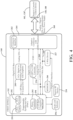
- FIG. 2 illustrates a system block diagram of components of the surgical system 100 of FIG. 1A , and more specifically, the control device 120 of the single-dongle example shown in FIG. 1A .
- the control device 120 includes a first communication device 202 and a radio frequency (RF) reader 204.
- the RF reader 204 may be configured to receive pairing information via RF signals.
- the first communication device 202 may be configured to wirelessly connect to a device based on the pairing information received by the RF reader 204.
- the first communication device 202 and the RF reader 204 may be integrated within the control device 120.
- the control device 120 includes a housing 190, illustrated as housings 192, 194 in FIG. 1A , and the first communication device 202 and the RF reader 204 may be integrated within the housing.
- the dongle 130 includes a second communication device 252 and a passive RF device 254.
- the passive RF device 254 may be configured to transmit the pairing information via RF signals to the RF reader 204 in response to the passive RF device 254 being within a threshold proximity of the RF reader 204.
- the second communication device 252 may be configured to wirelessly connect to a device based on the pairing information transmitted by the passive RF device 254.
- the passive RF device 254 may be configured to transmit information via RF signals after the passive RF device 254 is powered by RF signals from RF reader 204.
- the RF signals from the RF reader 204 power the passive RF device 254, enabling the passive RF device 254 to transmit the pairing information via RF signals back to the RF reader 204.
- the passive RF device 254 may be a passive RF tag.
- the passive RF device 254 may be replaced with other types of RF devices.
- the passive RF device 254 may be replaced with an RF device which may be powered internally, such as a battery-assisted RF tag or an active RF tag.
- the passive RF device 254 may be configured to transmit the pairing information using RF signals using a frequency defined between 30 kHz and 30 MHz, 400 MHz and 450 MHz, or 860 MHz and 960 MHz.
- the RF reader 204 of the control device 120 may be configured to receive RF signals with a frequency defined between 30 kHz and 30 MHz, 400 MHz and 450 MHz, or 860 MHz and 960 MHz.
- RF signals with a frequency defined between 30 kHz and 30 MHz have a longer wavelength than RF signals with a frequency defined between 400 MHz and 450 MHz or 860 MHz and 960 MHz.
- RF signals with a frequency defined between 30 kHz and 30 MHz are able to penetrate metallic substances and liquids more effectively, but have a more limited read range than RF signals with a frequency defined between 400 MHz and 450 MHz or 860 MHz and 960 MHz.
- Other frequency ranges other than those described herein are possible to operate the passive RF device 254.
- the RF reader 204 of the control device 120 may be configured to receive the pairing information from the passive RF device 254 in response to the passive RF device 254 being within the threshold proximity of the RF reader 204, as shown in FIG. 2 .
- the passive RF device 254 receives RF signals which are transmitted by the RF reader 204.
- the RF signals transmitted by the RF reader 204 power the passive RF device 254, enabling the passive RF device 254 to transmit the pairing information to the RF reader 204 via RF signals.
- the first and second communication devices 202, 252 may be configured to wirelessly connect based on the pairing information.
- the first communication device 202 may be configured to transmit control data to the second communication device 252, enabling the control device 120 to wirelessly communicate with the surgical console 102 to remotely control the surgical devices 110.
- first and second communication devices 202, 252 in FIG. 2 may use any communication network or protocol suitable for communicating control signals wirelessly.
- the first and second communication devices 202, 252 may use WiFi, Infrared, ZigBee, radio waves, cellular signals, any other suitable wireless network, or combinations thereof to communicate wirelessly.
- the communication network used by the first and second communication devices 202, 252 may differ from the RF signals used by the passive RF device 254 and the RF reader 204.
- the first and second communication devices 202, 252 are configured to operate on a frequency or range that is dictated by the designed communication network or protocol. For example, where the first and second communication devices 202, 252 use Bluetooth for wireless communication, the first and second communication devices 202, 252 may be configured to operate on a frequency between 2.4 and 2.485 GHz. Furthermore, as previously stated, the communication network used by the first and second communication devices 202, 252 may differ from the RF signals used by the passive RF device 254 and the RF reader 204. However, the first and second communication devices 202, 252 may be configured to operate on a frequency which may overlap or be greater than a frequency of operation of the passive RF device 254 and the RF reader 204.
- the passive RF device 254 and the RF reader 204 may be configured to transmit and receive RF signals with a frequency defined between 30 kHz and 30 MHz, 400 MHz and 450 MHz, or 860 MHz and 960 MHz.
- the first and second communication devices 202, 252 may be configured to operate on a frequency which overlaps the above-stated frequencies, or on a frequency greater than 1 GHz.
- the first and second communication devices 202, 252 are transceivers.
- each of the first and second communication devices 202, 252 is capable of receiving and transmitting control data.
- the first and second communication devices 202, 252 are different communication devices and may be configured to perform different tasks.
- the first communication device 202 may be a dedicated transmitter configured to transmit control data
- the second communication device 252 may be a dedicated receiver configured to receive control data.
- the pairing information transmitted by the passive RF device 254 of the dongle 130 and received by the RF reader 204 of the control device 120 may include a unique identification of the dongle 130.
- the pairing information may also include communication parameters associated with the dongle 130.
- the communication parameters associated with the dongle 130 may include a bits-per-character, a bits-per-second, a baud rate, parity bits, and start, stop, and mark bits.
- the pairing information includes other communication parameters.
- the pairing information may include communication parameters which may be specific to Bluetooth, WiFi, Infrared, ZigBee, radio waves, cellular signals, or any other communication network which the first communication device 202 or the second communication device 252 may use to wirelessly communicate with another device.
- the pairing information transmitted by the passive RF device 254 of the dongle 130 and received by the RF reader 204 of the control device 120 are encrypted by the dongle 130 and decrypted by the control device 120.
- the control data transmitted by the first communication device 202 of the control device 120 and received by the second communication device 252 of the dongle 130 may be encrypted by the control device 120 and decrypted by the dongle 130.
- the surgical system 100 allows for increased security of the pairing information and the control data. Additionally, the surgical system 100 may ensure that control devices 120 control a correct surgical device 110. Similarly, the surgical system 100 may ensure that surgical devices 110 are controlled by a correct control device 120.
- the dongle 130 may include a connector identifier 262.
- the connector identifier 262 is configured to determine a type of communication protocol used by the surgical console 102.
- the surgical console 102 to which the dongle 130 physically couples, may include a variety of surgical consoles 102, which may receive and transmit data using a variety of communication protocols.
- the surgical console 102 may use UART, I 2 C, CAN, 1-Wire, SPI, USB, UNI/O, or any other suitable communication protocol to receive and transmit data.
- the connector identifier 262 determines the type of communication protocol used by the surgical console 102.
- the dongle 130 may also include an adaptive connector 264.
- the adaptive connector 264 After the connector identifier 262 determines the type of communication protocol used by the surgical console 102, the adaptive connector 264 enables the dongle 130 to communicate with the surgical console 102 based on the communication protocol used by the surgical console 102. For example, the surgical console 102 may use UART as the communication protocol to receive and transmit data. As such, after the connector identifier 262 determines that the surgical console 102 uses UART to receive and transmit data, the adaptive connector 264 ensures that the dongle 130 communicates with the surgical console 102 using UART after the dongle coupling interface 330 of the dongle 130 is physically coupled to the dongle connection port 140 of the surgical console 102.
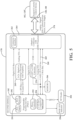
- FIG. 3 illustrates a system block diagram of the surgical system 100 in FIG. 1B , and more specifically, components of the first dongle 160 and the second dongle 170 of the double-dongle example shown in FIG. 1B .
- the first dongle 160 includes the described second communication device 252 and the described passive RF device 254.
- the second dongle 170 includes the described first communication device 202 and the described RF reader 204.
- the RF reader 204 of the second dongle 170 receives the pairing information from the passive RF device 254 of the first dongle 160.
- the first communication device 202 of the second dongle 170 then wirelessly connects to the second communication device 252 of the first dongle 160.
- the control device 120' wirelessly communicates with the surgical console 102 to remotely control the surgical devices 110.
- the first dongle 160 may be physically coupled to the surgical console 102 or to the control device 120'. More specifically, the dongle coupling interface 360 of the first dongle 160 may be physically coupled to the dongle connection port 140 of the surgical console 102 or to the dongle connection port 180 of the control device 120'.
- the second dongle 170 is coupled to the control device 120' in FIGS. 1B and 3 , the second dongle 170 may be physically coupled to the surgical console 102 or to the control device 120'. More specifically, the dongle coupling interface 370 of the second dongle 170 may be physically coupled to the dongle connection port 140 of the surgical console 102 or to the dongle connection port 180 of the control device 120'.
- the arrangement of the first and second dongles 160, 170 may be interchangeable with respect to what host device (e.g., surgical console 102, control device 120') the first and second dongles 160, 170 connect.
- one dongle 160, 170 connects to one host device 102, 120' while the other dongle 160, 170 connects to the other host device 102, 120'.
- the second dongle 170 is physically coupled to the control device 120'.
- the first dongle 160 is physically coupled to the control device 120'
- the second dongle 170 is physically coupled to the surgical console 102.
- the pairing information is transmitted by the passive RF device 254 of the first dongle 160 and received by the RF reader 204 of the second dongle 170.
- the pairing information may include a unique identification of the first dongle 160, which includes the passive RF device 254.
- the pairing information may also include communication parameters associated with the first dongle 160.
- the pairing information transmitted by the passive RF device 254 and received by the RF reader 204 may be encrypted by the first dongle 160 and decrypted by the second dongle 170.
- the communication device 202, 252 which is physically coupled to the control device 120' transmits the control data.
- the communication device 202, 252 which is physically coupled to the surgical console 102 receives the control data.
- the second dongle 170 encrypts the control data and the first dongle 160 decrypts the control data.
- the first dongle 160 encrypts the control data and the second dongle 170 decrypts the control data.
- the first dongle 160 and the second dongle 170 may each include the adaptive connector 264 and the connector identifier 262.
- the first and second dongles 160, 170 may physically couple to the control device 120' and to the surgical console 102.
- the control device 120' may be a variety of control devices and the surgical console 102 may be a variety of surgical consoles.
- the variety of control devices and the variety of surgical consoles may use different communication protocols to receive and transmit data.
- the connector identifiers 262 of the first and second dongles 160, 170 determine the communication protocols used by the control device 120' and the surgical console 102.
- the adaptive connectors 264 of the first and second dongles 160, 170 enable the first and second dongles 160, 170 to communicate with the control device 120' and with the surgical console 102 based on the communication protocols. This further adds to the universality and adaptability of the double-dongle configuration.
- FIGS. 4 and 5 illustrate an example system architecture of the first dongle 160 and the second dongle 170, respectively, of the double-dongle example.
- the second dongle 170 is similar to dongle 130.
- both the dongle 130 and the second dongle 170 include the first communication device 202, the RF reader 204, the connector identifier 262, and the adaptive connector 264.
- the second dongle 170 may be physically coupled to the surgical console 102 or the control device 120', the dongle 130 may be physically coupled to the control device 120.
- any components of the second dongle 170 shown in FIG. 5 and described herein may be applied to the dongle 130.
- the first and second dongles 160, 170 may be physically coupled to the surgical console 102 or to the control device 120'.
- the first and second dongles 160, 170 may be physically coupled to the surgical console 102 or to the control device 120'
- the first dongle 160 or the second dongle 170 is physically coupled to the dongle connection port 140 of the surgical console 102
- the other of the first dongle 160 or the second dongle 170 is physically coupled to the dongle connection port 180 of the control device 120'. Therefore, if the first dongle 160 is physically coupled to the surgical console 102, then the second dongle 170 is physically coupled to the control device 120'.
- the first dongle 160 is physically coupled to the control device 120', then the second dongle 170 is physically coupled to the surgical console 102.
- the first and second communication devices 202, 252 are Programmable System-on-Chip (PSoC) integrated circuits.
- the PSoC integrated circuits include a Bluetooth Low Energy (BLE) engine 291 and a BLE antenna 292.
- BLE Bluetooth Low Energy
- the PSoC integrated circuit may communicate wirelessly with other devices using Bluetooth.
- the PSoC integrated circuit includes a microcontroller 293, which may control the BLE engine 291 and the BLE antenna 292 and other components of the PSoC integrated circuit.
- the microcontroller 293 may also control inputs and outputs of the PSoC integrated circuit, which are shown in FIGS. 4 and 5 and described below.
- the PSoC integrated circuit also includes a Controller Area Network (CAN) bus controller and driver 294, which allows the PSoC integrated circuit to receive and transmit CAN messages.
- CAN Controller Area Network
- first and second communication devices 202, 252 are illustrated as PSoC integrated circuits, the first and second communication devices 202, 252 may be any other circuits suitable for wireless communication, such as ASIC, SOC, etc. In other examples, the first and second communication devices 202, 252 may be any device capable of wirelessly communicating with another device. In such examples, the first and second communication devices 202, 252 may include a controller, or a controller may be coupled to the first and second communication devices 202, 252.
- the PSoC integrated circuits include the BLE engine 291 and the BLE antenna 292 for communicating wirelessly with other devices using Bluetooth
- the first and second communication devices 202, 252 may communicate with other devices using any other suitable wireless network, such as WiFi, Infrared, ZigBee, radio waves, cellular signals, or combinations thereof.
- FIGS. 4 and 5 illustrate that the first and second dongles 160, 170 may be configured to receive power from the surgical console 102 and the control device 120'.
- the dongles 130, 160, 170 do not include an internal power supply.
- the dongles 130, 160, 170 and some components thereof, such as the first and second communication devices 202, 252 may be powered by the surgical console 102 through the dongle connection port 140 or by the control device 120' through the dongle connection port 180.
- operation of some components of the dongles 130, 160, 170 may occur after the dongles 130, 160, 170 are physically coupled to the surgical console 102 or the control device 120'.
- the second communication device 252 of the first dongle 160 may wirelessly connect to the first communication device 202 of the second dongle 170 after the first dongle 160 is physically coupled to the surgical console 102.
- the second communication device 252 of the dongle 130 may wirelessly connect to the first communication device 202 of the control device 120 after the dongle 130 is physically coupled to the surgical console 102.
- the passive RF device 254 of the dongle 130 and the first dongle 160 may be powered by outside sources, such as the RF reader 204, and may therefore operate before the dongle 130 or the first dongle 160 are physically coupled.
- FIGS. 4 and 5 also illustrate inputs and outputs of the first and second communication devices 202, 252 and other components of the first and second dongles 160, 170.
- the first and second communication devices 202, 252 and the adaptive connector 264 share digital I/Os, as well as a UART/I 2 C/CAN bus 269 and a 1-Wire bus 268.
- the first and second communication devices 202, 252 may communicate with the surgical console 102 and the control device 120' using a variety of data types.
- the first communication device 202 may communicate serial data with the RF reader 204 via a UART bus.
- the first and second communication devices 202, 252 are configured to transfer digital SPI bus data and digital control I/O data to the surgical console 102 by converting the digital SPI bus data and the digital control I/O data to analog data using a 2-channel digital to analog converter with amplifier 295 and transferring the data using Analog I/Os.
- the first and second communication devices 202, 252 are configured to receive analog data from the surgical console 102 after the analog data has been converted to digital data using the 2-channel digital to analog converter with amplifier 295.
- the battery life is converted and communicated from the first or second communication device 202, 252 to the surgical console 102 via the 2-channel digital to analog converter with amplifier 295.
- the dongles 130, 160, 170 may include different connections than or may omit some of the connections shown in FIGS. 4 and 5 .
- the first or second communication device 202, 252 may be an integrated circuit other than a PSoC integrated device.
- the first or second communication devices 202, 252 may include inputs and outputs that vary from the inputs and outputs of the first and second communication devices 202, 252 shown in FIGS. 4 and 5 .
- the first or second communication device 202, 252 is an integrated circuit other than a PSoC integrated device, the 2-channel digital to analog converter with amplifier 295 may not be required.
- the UART/I 2 C/CAN bus 269 and the 1-Wire bus 268 may be omitted or replaced with a bus for a different communication protocol.
- the adaptive connector 264 is coupled to a UART/I 2 C/CAN bus 269 and a 1-Wire bus 268.
- the adaptive connector 264 in FIGS. 4 and 5 may enable the first and second dongles 160, 170 to communicate with the surgical console 102 or the control device 120' using UART, I 2 C, CAN, or 1-Wire.
- the surgical console 102 may use UART, I 2 C, CAN, 1-Wire, SPI, USB, UNI/O, or any other suitable communication protocols.
- the connector identifier 262 of the first dongle 160 determines that the communication protocol used by the surgical console 102 to receive and transmit data is 1-Wire. Accordingly, the adaptive connector 264 enables the first dongle 160 to communicate with the surgical console 102 by transmitting data to the surgical console 102 from the 1-Wire bus 268.
- the adaptive connector 264 may also be configured to communicate using communication protocols other than UART, I 2 C, CAN, and 1-Wire, such as SPI, USB, or UNI/O.
- communication protocols other than UART, I 2 C, CAN, and 1-Wire, such as SPI, USB, or UNI/O.
- the adaptive connector 264 may be configured to communicate using USB.
- the first and second dongles 160, 170 include a UART to USB converter 270.
- the first and second dongles 160, 170 may include a specific bus for each communication protocol or may include a bus for different groupings of communication protocols.
- the first and second dongles 160, 170 may include a UART bus, an I 2 C bus, a CAN bus, a UART/I 2 C bus, a UART/CAN bus, or an I 2 C/CAN bus instead of the UART/I 2 C/CAN bus 269.
- the first and second dongles 160, 170 may include memory 266.
- the memory 266 is coupled to the UART/I 2 C/CAN bus 269. It should be noted that the memory 266 may be coupled to other components of the first and second dongles 160, 170. For example, the memory 266 may be coupled to the digital I/Os of the first and second dongles 160, 170.
- the memory 266 may be any memory suitable for storage of data and computer-readable instructions.
- the memory 266 may be a local memory or an external memory embodied as random access memory (RAM), non-volatile RAM (NVRAM), flash memory, or any other suitable form of memory.
- a 1-Wire device 267 is coupled to the second communication device 252 and to the 1-Wire bus 268.
- the 1-Wire device 267 may be a 1-Wire memory, such as local memory or an external memory embodied as random access memory (RAM), non-volatile memory (e.g., a 1-Wire EEPROM or a 1-Wire NVSRAM), flash memory, or any other suitable form of memory.
- the 1-Wire memory may be configured to store a configuration of the surgical console 102 or the control device 120'.
- the 1-Wire device 267 may be a 1-Wire sensor, such as a temperature, current, or voltage sensor.
- the 1-Wire device 267 may also be a 1-Wire time counter or a 1-Wire battery monitor.
- the first and second dongles 160, 170 shown in FIGS. 4 and 5 may be omitted.
- the first and second dongles 160, 170 include an RGB LED Indicator 296.
- the first and second dongles 160, 170 may omit the RGB LED Indicator 296.
- the memory 266 or the 1-Wire device 267 may be omitted.
- the UART/I 2 C/CAN bus 269 or the 1-Wire bus 268 may be omitted.
- the microcontroller 293 of the first and second dongles 160, 170 is configured to control, manage or otherwise execute any of the aforementioned capabilities of the first and second dongles 160, 170.
- capabilities include, but are not limited to, pairing using the RF reader 204, connector identification using the connector identifier 262, bus communication adaptation using the adaptive connector 264, control signal transmission using the first and second communication devices 202, 252, operation of the indicator 296, retrieval and saving of data from the memory 266 or the 1-Wire device 267 (in instances where the 1-Wire device 267 is a 1-Wire memory), or any other operation triggered by the host device (surgical console 102, control device 120'), and the like.
- a method of operating the surgical system 100 is shown in FIG. 6 .
- the method includes a step 402 of establishing the threshold proximity between the passive RF device 254 of the dongle 130 and the RF reader 204 of the control device 120 or a step 402' of establishing the threshold proximity between the passive RF device 254 of the first dongle 160 and the RF reader 204 of the second dongle 170; a step 404 of receiving the pairing information from the passive RF device 254; a step 406 of physically coupling the dongle 130 to the dongle connection port 140 of the surgical console 102 or a step 406' of physically coupling the first dongle 160 and the second dongle 170 to the dongle connection port 140 of the surgical console 102 and to the dongle connection port 180 of the control device 120'; a step 408 of establishing a wireless connection between the first communication device 202 and the second communication device 252 based on the pairing information; and a step 410 of remotely and wirelessly controlling the surgical device 110 using the wireless connection.
- the method includes step 402.
- the threshold proximity is established between the passive RF device 254 of the dongle 130 and the RF reader 204 of the control device 120.
- the method includes step 402'.
- the threshold proximity is established between the passive RF device 254 of the first dongle 160 and the RF reader 204 of the second dongle 170.
- the threshold proximity may be defined as a distance between the passive RF device 254 and the RF reader 204 that allows the RF reader 204 to receive the pairing information from the passive RF device 254.
- the passive RF device 254 may be configured to transmit the pairing information using RF signals with a variety of frequencies, which may affect a read range of the RF signals. For example, where the pairing information is transmitted using RF signals with a lower frequency, and thus a longer wavelength, the RF signals have a larger read range, allowing for a greater threshold proximity. Therefore, the threshold proximity may vary according to the frequency of the RF signals. For example, the threshold proximity may be on an order of centimeters or inches.
- the threshold proximity may be on an order of feet or meters. In still other examples, the threshold proximity may be greater than 50 feet. In yet another example, threshold proximity may require a proximity "tapping" between devices that include the passive RF device 254 and the RF reader 204.
- control device 120 may be disposed in a sterile field and the surgical console 102 may be disposed in a non-sterile field.
- step 402 may include a step of moving the dongle 130 into the sterile field to establish the threshold proximity between the passive RF device 254 of the dongle 130 and the RF reader 204 of the control device 120, or a step of moving the control device 120 into the non-sterile field to establish the threshold proximity between the passive RF device 254 of the dongle 130 and the RF reader 204 of the control device 120.
- the control device 120' may be disposed in a sterile field and the surgical console 102 may be disposed in a non-sterile field.
- step 402 may include a step of moving the first or second dongle 160, 170 into the sterile or non-sterile field to establish a threshold proximity between the passive RF device 254 of the first dongle 160 and the RF reader 204 of the second dongle 170.
- the passive RF device 254 is powered during step 402.
- the passive RF device 254 may be replaced with an RF device which may be powered internally, such as a battery-assisted RF tag or an active RF tag.
- the battery-assisted RF tag or the active RF tag may be powered prior to step 402.
- the passive RF device 254 transmits the pairing information to the RF reader 204 during step 404.
- the passive RF device 254 of the dongle 130 transmits pairing information to the RF reader 204 of the control device 120.
- the passive RF device 254 of the first dongle 160 transmits pairing information to the RF reader 204 of the second dongle 170.
- the wireless connection is established between the first and second communication devices 202, 252 based on the pairing information received from the passive RF device 254.
- the wireless connection is established between the first communication device 202 of the control device 120 and the second communication device 252 of the dongle 130.
- the wireless connection is established between the first communication device 202 of the second dongle 170 and the second communication device 252 of the first dongle 160.
- the method shown in FIG. 6 may include a step of encrypting the pairing information and a step 414 of decrypting the pairing information.
- the dongle 130 which includes the passive RF device 254, may encrypt the pairing information; and the control device 120, which includes the RF reader 204, may decrypt the pairing information during step 414.
- the first dongle 160 which includes the passive RF device 254, may encrypt the pairing information; and the second dongle 170, which includes the RF reader 204, may decrypt the pairing information.
- encryption of the pairing information may occur at any time prior to step 404, when the pairing information is transmitted.
- the pairing information may be encrypted at a time of manufacture of the passive RF device 254.
- the pairing information may be encrypted after the passive RF device 254 is powered.
- the pairing information may be encrypted after the passive RF device 254 is powered by RF signals from the RF reader 204 during step 402.
- step 414 may occur at any time after step 404, the step of receiving the pairing information from the passive RF device 254, and prior to step 408, the step of establishing a wireless connection between the first and second communication devices 202, 252.
- the step 414 of decrypting the pairing information with the RF reader 204 may occur after the pairing information is received by the RF reader 204 during step 404, but before establishing the wireless connection between the first and second communication devices 202, 252 based on the pairing information during step 408.
- step 406 the method proceeds to step 406 in the single-dongle example.
- the dongle 130 is physically coupled to the dongle connection port 140 of the surgical console 102.
- the control device 120 is disposed in a sterile field and the surgical console 102 may be disposed in a non-sterile field.
- step 406 of physically coupling the dongle 130 to the dongle connection port 140 of the surgical console 102 may include a step of moving the dongle 130 into the non-sterile field.
- step 406' in the double-dongle example.
- the first dongle 160 and the second dongle 170 are physically coupled to the dongle connection ports 140, 150 of the surgical console 102 and the control device 120'.
- the second dongle 170 is physically coupled to the dongle connection port 180 of the control device 120' and the first dongle 160 is physically coupled to the dongle connection port 140 of the surgical console 102 during step 406'.
- the second dongle 170 is physically coupled to the dongle connection port 140 of the surgical console 102 and the first dongle 160 is physically coupled to the dongle connection port 180 of the control device 120' during step 406'.
- steps 406, 406' are illustrated as occurring prior to step 408. However, steps 406, 406' may occur concurrent to or after step 408 (as well as prior to step 408).
- the wireless connection may be established between the first and second communication devices 202, 252 prior to the dongles 130, 160, 170 being physically coupled to the surgical console 102 or the control device 120' via the dongle connection ports 140, 180. This may occur in examples where the dongles 130, 160, 170, and thus the first and second communication devices 202, 252, are powered internally or are powered prior to being physically coupled to the surgical console 102 or to the control device 120'.
- the dongles 130, 160, 170 and thus, the first and second communication devices 202, 252 may be powered by the surgical console 102 and/or the control device 120' via the dongle connection ports 140, 180. In such examples, steps 406, 406' may occur prior to step 408.
- step 410 the surgical device 110 is remotely controlled by the control device 120 using the wireless connection.
- step 410 may include a step 416 of encrypting the control data and a step 418 of decrypting the control data.
- the control device 120 may encrypt the control data and the dongle 130 may decrypt the control data.
- the dongle 160, 170 physically coupled to the control device 120' may encrypt the control data
- the dongle 170, 160 physically coupled to the surgical console 102 may decrypt the control data.
- control devices 120, 120' By remotely controlling the surgical devices 110 using control devices 120, 120', the control devices 120, 120' no longer require cables and connectors, which clutter the workspace and create obstacles in surgical environments.
- the above-described systems and methods disclose a quick and user-friendly means of establishing the wireless connection between the first and second communication devices 202, 252.
- the pairing information is received by the RF reader 204 by simply establishing the threshold proximity between the RF reader 204 and the passive RF device 254.
- the wireless connection between the first and second communication devices 202, 252 is then automatically established using this pairing information.
- the systems and methods discussed herein do not require a user to manually provide the pairing information to the first and second communication devices 202, 252.
- the wireless connection between the first and second communication devices 202, 252 is established in a quick and user-friendly way, minimizing errors from users.
- any dongle 130 may be wirelessly connected to any control device 120 and any first dongle 160 may be wirelessly connected to any second dongle 170. Therefore, from an inventory management perspective, dongles 130 need not be paired with a specific control device 120 and first dongles 160 need not be specifically paired to a second dongle 170. Furthermore, the dongles 130, 160, 170 may communicate with a variety of surgical consoles 102 due to the connector identifier 262 and the adaptive connector 264 of the dongles 130, 160, 170. Therefore, from an inventory management perspective, the dongles 130, 160, 170 need not be paired with specific surgical consoles 102. In this way, dongles 130, 160, 170 are easily replaced and inventories of the dongles 130, 160, 170 are easily managed.
Landscapes
- Health & Medical Sciences (AREA)
- Engineering & Computer Science (AREA)
- Biomedical Technology (AREA)
- Life Sciences & Earth Sciences (AREA)
- Surgery (AREA)
- Public Health (AREA)
- General Health & Medical Sciences (AREA)
- Medical Informatics (AREA)
- Computer Security & Cryptography (AREA)
- Veterinary Medicine (AREA)
- Animal Behavior & Ethology (AREA)
- Molecular Biology (AREA)
- Heart & Thoracic Surgery (AREA)
- Nuclear Medicine, Radiotherapy & Molecular Imaging (AREA)
- Signal Processing (AREA)
- Computer Networks & Wireless Communication (AREA)
- General Business, Economics & Management (AREA)
- Primary Health Care (AREA)
- Epidemiology (AREA)
- Business, Economics & Management (AREA)
- Physics & Mathematics (AREA)
- Pathology (AREA)
- Oral & Maxillofacial Surgery (AREA)
- Electromagnetism (AREA)
- Otolaryngology (AREA)
- Selective Calling Equipment (AREA)
- Plasma & Fusion (AREA)
- Surgical Instruments (AREA)
Claims (15)
- Chirurgisches System (100), umfassend:eine chirurgische Konsole (102), die zum Betreiben einer chirurgischen Vorrichtung (110, 112, 114, 116) eingerichtet ist und einen Verbindungsanschluss (140) umfasst;eine Steuerungsvorrichtung (120), die zur Kommunikation mit der chirurgischen Konsole (102) eingerichtet ist, um die chirurgische Vorrichtung (110, 112, 114, 116) fernzusteuern, und die eine erste Kommunikationsvorrichtung (202) und eine Hochfrequenz (RF)-Lesevorrichtung (204) umfasst, wobei die Steuerungsvorrichtung (120) ferner als eine mit dem Fuß bedienbare Steuerungsvorrichtung, eine mit der Hand bedienbare Steuerungsvorrichtung oder eine mobile Computervorrichtung definiert ist;einen Dongle (130), der eingerichtet ist, um physisch mit dem Verbindungsanschluss (140) der chirurgischen Konsole (102) zu koppeln, und der eine zweite Kommunikationsvorrichtung (252) und eine passive RF-Vorrichtung (254) umfasst, wobei der Dongle (130) eingerichtet ist, um über den Verbindungsanschluss (140) der chirurgischen Konsole (102) mit Strom versorgt zu werden;wobei die RF-Lesevorrichtung (204) der Steuerungsvorrichtung (120) eingerichtet ist, um Kopplungsinformationen von der passiven RF-Vorrichtung (254) des Dongles (130) als Reaktion darauf zu empfangen, dass sich die passive RF-Vorrichtung (254) innerhalb einer Schwellenwertenähe der RF-Lesevorrichtung (204) befindet; undwobei die erste und die zweite Kommunikationsvorrichtung (202, 252) eingerichtet sind, um sich drahtlos auf der Grundlage der Kopplungsinformationen zu verbinden, um es dadurch der Steuerungsvorrichtung (120) zu ermöglichen, drahtlos mit der chirurgischen Konsole (102) zu kommunizieren, um die chirurgische Vorrichtung (110, 112, 114, 116) fernzusteuern.
- Chirurgisches System (100) nach einem der vorhergehenden Ansprüche, wobei der Verbindungsanschluss (140) der chirurgischen Konsole (102) in Abwesenheit des Dongles (130) so eingerichtet ist, dass er einen Stecker eines Kabels zur Verbindung mit der Steuerungsvorrichtung (120) aufnehmen kann.
- Chirurgisches System (100) nach einem der vorangehenden Ansprüche, wobei die erste und die zweite Kommunikationsvorrichtungen (202, 252) eingerichtet sind, um eine drahtlose Verbindung auf der Grundlage der Kopplungsinformationen in Reaktion darauf herzustellen, dass der Dongle (130) physisch mit dem Verbindungsanschluss (140) der chirurgischen Konsole (102) gekoppelt ist.
- Chirurgisches System (100) nach einem der vorangehenden Ansprüche, wobei die Kopplungsinformationen mindestens eine eindeutige Identifikation des Dongles (130) und dem Dongle (130) zugeordnete Kommunikationsparameter umfassen.
- Chirurgisches System (100) nach einem der vorangehenden Ansprüche, wobei der Dongle (130) eingerichtet ist, um die Kopplungsinformationen zu verschlüsseln, und die Steuerungsvorrichtung (120) eingerichtet ist, um die Kopplungsinformationen zu entschlüsseln.
- Chirurgisches System (100) nach einem der vorangehenden Ansprüche, wobei die erste Kommunikationsvorrichtung (202) eingerichtet ist, um Steuerungsdaten an die zweite Kommunikationsvorrichtung (252) zu übertragen, so dass die Steuerungsvorrichtung (120) die chirurgische Vorrichtung (110, 112, 114, 116) unter Verwendung der Steuerungsdaten fernsteuert, und wobei die Steuerungsvorrichtung (120) eingerichtet ist, um die Steuerungsdaten zu verschlüsseln, und der Dongle (130) eingerichtet ist, um die Steuerungsdaten zu entschlüsseln.
- Chirurgisches System (100) nach einem der vorangehenden Ansprüche, wobei die Steuerungsvorrichtung (120) ein Gehäuse umfasst und wobei die erste Kommunikationsvorrichtung (202) und die RF-Lesevorrichtung (204) in das Gehäuse integriert sind.
- Chirurgisches System (100) nach einem der vorangehenden Ansprüche, wobei die RF-Lesevorrichtung (204) und die passive RF-Vorrichtung (254) eingerichtet sind, auf einer Frequenz zu arbeiten, die zwischen 30 kHz und 30 MHz, 400 MHz und 450 MHz oder 860 MHz und 960 MHz liegt.
- Chirurgisches System (100) nach einem der vorangehenden Ansprüche, wobei die erste und die zweite Kommunikationsvorrichtung (202, 252) eingerichtet sind, mit einer Frequenz von mehr als 1 GHz zu arbeiten.
- Chirurgisches System (100) nach einem der vorangehenden Ansprüche, wobei der Dongle (130) eine Verbinder-Kennung und einen adaptiven Verbinder umfasst, und wobei die Verbinder-Kennung eingerichtet ist, um einen Typ eines Kommunikationsprotokolls zu bestimmen, das von der chirurgischen Konsole (102) zum Empfangen und Senden von Daten verwendet wird, und der adaptive Verbinder eingerichtet ist, um mit der chirurgischen Konsole (102) basierend auf dem Typ des von der chirurgischen Konsole (102) verwendeten Kommunikationsprotokolls zu kommunizieren.
- Verfahren zum Betreiben eines chirurgischen Systems (100), wobei das chirurgische System (100) umfasst: eine chirurgische Konsole (102), die zum Betreiben einer chirurgischen Vorrichtung (110, 112, 114, 116) eingerichtet ist und einen Verbindungsanschluss (140) umfasst, eine Steuerungsvorrichtung (120), die zur Kommunikation mit der chirurgischen Konsole (102) eingerichtet ist, um die chirurgische Vorrichtung (110, 112, 114, 116 zu steuern, und die eine erste Kommunikationsvorrichtung (202) und eine Hochfrequenz (RF)-Lesevorrichtung (204) umfasst, und einen Dongle (130), der eine zweite Kommunikationsvorrichtung (252) und eine passive RF-Vorrichtung (254) umfasst, wobei das Verfahren die folgenden Schritte umfasst:Herstellen einer Schwellenwertnähe zwischen der passiven RF-Vorrichtung (254) des Dongles (130) und der RF-Lesevorrichtung (204) der Steuerungsvorrichtung (120), wobei die Steuerungsvorrichtung (120) in einem sterilen Feld angeordnet ist und wobei der Schritt des Herstellens der Schwellenwertnähe zwischen der passiven RF-Vorrichtung (254) des Dongles (130) und der RF-Lesevorrichtung (204) der Steuerungsvorrichtung (120) einen Schritt des Bewegens des Dongles (130) in das sterile Feld umfasst, und wobei die Steuerungsvorrichtung (120) ferner als eine fußbetätigte Steuerungsvorrichtung, eine handbetätigte Steuerungsvorrichtung und/oder eine mobile Computervorrichtung definiert ist;Empfangen von Kopplungsinformationen von der passiven HF-Vorrichtung (254) des Dongles (130) mit der HF-Lesevorrichtung (204) der Steuerungsvorrichtung (120) als Reaktion darauf, dass sich die passive HF-Vorrichtung (254) und die HF-Lesevorrichtung (204) innerhalb der Schwellenwertnähe befinden;physisches Koppeln des Dongles (130) mit dem Verbindungsanschluss (140) der chirurgischen Konsole (102);Herstellen einer drahtlosen Verbindung zwischen der ersten und der zweiten Kommunikationsvorrichtung (202, 252) auf der Grundlage der Kopplungsinformationen,wobei die drahtlose Verbindung eingerichtet ist, um die chirurgische Vorrichtung (110, 112, 114, 116) mit der Steuerungsvorrichtung (120) unter Verwendung der drahtlosen Verbindung ferngesteuert und drahtlos zu steuern.
- Verfahren nach Anspruch 11, wobei der Dongle (130) keine interne Stromversorgung aufweist und wobei das Verfahren ferner einen Schritt der Stromversorgung des Dongles (130) über den Verbindungsanschluss (140) umfasst.
- Verfahren nach einem der Ansprüche 11 oder 12, ferner umfassend die Schritte:Verschlüsseln der Kopplungsinformationen mit dem Dongle (130); undEntschlüsseln der Kopplungsinformationen mit der Steuerungsvorrichtung (120).
- Verfahren nach einem der Ansprüche 11 - 13, ferner umfassend einen Schritt eines Übertragens der Steuerungsdaten mit der Steuerungsvorrichtung (120) an die chirurgische Konsole (102) über die erste Kommunikationsvorrichtung (202), und wobei das Verfahren ferner die folgenden Schritte umfasst:Verschlüsseln der Steuerungsdaten mit der Steuerungsvorrichtung (120); undEntschlüsseln der Steuerungsdaten mit dem Dongle (130).
- Verfahren nach einem der Ansprüche 11 - 14, wobei die chirurgische Konsole (102) eingerichtet ist, um in einem unsterilen Bereich angeordnet zu werden, und wobei das Verfahren ferner einen Schritt des Bewegens des Dongles (130) in den unsterilen Bereich umfasst, um den Dongle (130) physisch mit dem Verbindungsanschluss (140) der chirurgischen Konsole (102) zu verbinden.
Applications Claiming Priority (2)
| Application Number | Priority Date | Filing Date | Title |
|---|---|---|---|
| US201862640774P | 2018-03-09 | 2018-03-09 | |
| PCT/US2019/021128 WO2019173574A1 (en) | 2018-03-09 | 2019-03-07 | Systems and methods for remotely controlling a surgical instrument of console-based surgical systems |
Publications (2)
| Publication Number | Publication Date |
|---|---|
| EP3761885A1 EP3761885A1 (de) | 2021-01-13 |
| EP3761885B1 true EP3761885B1 (de) | 2024-09-11 |
Family
ID=65904550
Family Applications (1)
| Application Number | Title | Priority Date | Filing Date |
|---|---|---|---|
| EP19713261.6A Active EP3761885B1 (de) | 2018-03-09 | 2019-03-07 | Systeme und verfahren zur fernsteuerung eines chirurgischen instruments von konsolenbasierten chirurgischen systemen |
Country Status (8)
| Country | Link |
|---|---|
| US (2) | US11533764B2 (de) |
| EP (1) | EP3761885B1 (de) |
| JP (2) | JP7257409B2 (de) |
| KR (2) | KR20250012006A (de) |
| CN (1) | CN111867485B (de) |
| AU (1) | AU2019230055B2 (de) |
| CA (1) | CA3093299A1 (de) |
| WO (1) | WO2019173574A1 (de) |
Families Citing this family (33)
| Publication number | Priority date | Publication date | Assignee | Title |
|---|---|---|---|---|
| US11191528B2 (en) | 2015-07-09 | 2021-12-07 | DePuy Synthes Products, Inc. | External hand control for surgical power tool |
| EP3761885B1 (de) * | 2018-03-09 | 2024-09-11 | Stryker Corporation | Systeme und verfahren zur fernsteuerung eines chirurgischen instruments von konsolenbasierten chirurgischen systemen |
| US20200078113A1 (en) | 2018-09-07 | 2020-03-12 | Ethicon Llc | Port presence detection system for modular energy system |
| US12144136B2 (en) | 2018-09-07 | 2024-11-12 | Cilag Gmbh International | Modular surgical energy system with module positional awareness with digital logic |
| US11804679B2 (en) | 2018-09-07 | 2023-10-31 | Cilag Gmbh International | Flexible hand-switch circuit |
| US11923084B2 (en) * | 2018-09-07 | 2024-03-05 | Cilag Gmbh International | First and second communication protocol arrangement for driving primary and secondary devices through a single port |
| US11918269B2 (en) | 2018-09-07 | 2024-03-05 | Cilag Gmbh International | Smart return pad sensing through modulation of near field communication and contact quality monitoring signals |
| US11218822B2 (en) | 2019-03-29 | 2022-01-04 | Cilag Gmbh International | Audio tone construction for an energy module of a modular energy system |
| USD939545S1 (en) | 2019-09-05 | 2021-12-28 | Cilag Gmbh International | Display panel or portion thereof with graphical user interface for energy module |
| DE102020108701A1 (de) | 2020-03-30 | 2021-09-30 | Olympus Winter & Ibe Gmbh | Kopplung von Fußschalter und medizintechnischem Gerät |
| KR102465100B1 (ko) | 2020-08-18 | 2022-11-08 | 홍기용 | 이쑤시개 디스펜서 |
| EP4016491A1 (de) * | 2020-12-16 | 2022-06-22 | Leica Instruments (Singapore) Pte. Ltd. | Kommunikationssystem für eine chirurgische vorrichtung, chirurgisches system und verfahren zur steuerung |
| US12004824B2 (en) | 2021-03-30 | 2024-06-11 | Cilag Gmbh International | Architecture for modular energy system |
| US11963727B2 (en) | 2021-03-30 | 2024-04-23 | Cilag Gmbh International | Method for system architecture for modular energy system |
| US11950860B2 (en) | 2021-03-30 | 2024-04-09 | Cilag Gmbh International | User interface mitigation techniques for modular energy systems |
| US11978554B2 (en) * | 2021-03-30 | 2024-05-07 | Cilag Gmbh International | Radio frequency identification token for wireless surgical instruments |
| US11968776B2 (en) | 2021-03-30 | 2024-04-23 | Cilag Gmbh International | Method for mechanical packaging for modular energy system |
| US11857252B2 (en) | 2021-03-30 | 2024-01-02 | Cilag Gmbh International | Bezel with light blocking features for modular energy system |
| US12040749B2 (en) | 2021-03-30 | 2024-07-16 | Cilag Gmbh International | Modular energy system with dual amplifiers and techniques for updating parameters thereof |
| US12235697B2 (en) | 2021-03-30 | 2025-02-25 | Cilag Gmbh International | Backplane connector attachment mechanism for modular energy system |
| US12228987B2 (en) | 2021-03-30 | 2025-02-18 | Cilag Gmbh International | Method for energy delivery for modular energy system |
| US11980411B2 (en) | 2021-03-30 | 2024-05-14 | Cilag Gmbh International | Header for modular energy system |
| US12369994B2 (en) | 2021-03-30 | 2025-07-29 | Cilag Gmbh International | Modular energy system with multi-energy port splitter for multiple energy devices |
| US12462439B2 (en) | 2021-04-14 | 2025-11-04 | Cilag Gmbh International | Risk based prioritization of display aspects in surgical field view |
| CN113691559B (zh) * | 2021-09-07 | 2022-06-24 | 滨州职业学院 | 手术机器人主手通讯加密系统 |
| DE102022107415A1 (de) | 2022-03-28 | 2023-09-28 | Olympus Winter & Ibe Gmbh | Chirurgisches Gerätesystem, Verfahren zum Betrieb desselben und drahtloser Lizenztag |
| CN114886511B (zh) * | 2022-04-21 | 2024-09-06 | 厚凯(北京)医疗科技有限公司 | 手术器械的控制方法、手术系统、手术设备以及存储介质 |
| US12079460B2 (en) | 2022-06-28 | 2024-09-03 | Cilag Gmbh International | Profiles for modular energy system |
| CN115458143B (zh) * | 2022-09-16 | 2023-05-23 | 兰州大学 | 基于神经网络的无源植入式医疗器械射频发热评估方法 |
| JP2026502592A (ja) | 2023-01-16 | 2026-01-23 | ストライカー・コーポレイション | 単一のフットスイッチで複数の手術コンソールを制御するためのシステムおよび方法 |
| WO2025151756A1 (en) | 2024-01-10 | 2025-07-17 | Stryker Corporation | Attenuation of common mode and differential mode currents by chokes in surgical systems |
| WO2025208408A1 (en) * | 2024-04-03 | 2025-10-09 | Qualcomm Incorporated | Proximity determination for ambient wireless devices |
| US12413853B1 (en) * | 2024-04-24 | 2025-09-09 | Damon William Meledones | Cinema camera communication and control device |
Family Cites Families (75)
| Publication number | Priority date | Publication date | Assignee | Title |
|---|---|---|---|---|
| CA2374344C (en) * | 2001-03-01 | 2006-02-21 | Research In Motion Limited | Multifunctional charger system and method |
| US6892052B2 (en) | 2002-03-26 | 2005-05-10 | Nokia Corporation | Radio frequency identification (RF-ID) based discovery for short range radio communication |
| US7565108B2 (en) | 2002-03-26 | 2009-07-21 | Nokia Corporation | Radio frequency identification (RF-ID) based discovery for short range radio communication with reader device having transponder functionality |
| US7883458B2 (en) | 2003-06-27 | 2011-02-08 | Stryker Corporation | System for remotely controlling two or more medical devices |
| US9035741B2 (en) | 2003-06-27 | 2015-05-19 | Stryker Corporation | Foot-operated control console for wirelessly controlling medical devices |
| US10105140B2 (en) | 2009-11-20 | 2018-10-23 | Covidien Lp | Surgical console and hand-held surgical device |
| US20050221895A1 (en) | 2004-04-02 | 2005-10-06 | Microsoft Corporation | Binding of wireless game controller to host |
| BRPI0517225A (pt) | 2004-11-01 | 2008-09-30 | Stryker Corp | sistema e método para controlar pelo menos um dispositivo médico por uma conexão sem fios segura |
| US7568619B2 (en) | 2004-12-15 | 2009-08-04 | Alcon, Inc. | System and method for identifying and controlling ophthalmic surgical devices and components |
| CA2803828C (en) | 2005-03-31 | 2015-11-24 | Alcon, Inc. | Footswitch operable to control a surgical system |
| US7370978B2 (en) * | 2005-05-09 | 2008-05-13 | Anderson Daryl E | Encrypting data |
| US20070030517A1 (en) * | 2005-08-04 | 2007-02-08 | Staccato Communications, Inc. | Smart wireless dongle |
| JP2007110350A (ja) | 2005-10-12 | 2007-04-26 | Sony Corp | リモートコントロールシステムとリモートコントロール装置およびリモートコントロール方法 |
| US7643798B2 (en) | 2005-12-09 | 2010-01-05 | Sony Ericsson Mobile Communications Ab | Passive NFC activation of short distance wireless communication |
| JP2008074600A (ja) * | 2006-09-25 | 2008-04-03 | Toppan Forms Co Ltd | 物品管理システム及び無線通信媒体 |
| US7706771B2 (en) * | 2007-02-08 | 2010-04-27 | Broadcom Corporation | Inductive powering for a mobile communication device and method for use therewith |
| US9050123B2 (en) | 2007-04-16 | 2015-06-09 | Smith & Nephew, Inc. | Powered surgical system |
| US8768251B2 (en) | 2007-05-17 | 2014-07-01 | Abbott Medical Optics Inc. | Exclusive pairing technique for Bluetooth compliant medical devices |
| US8461978B2 (en) * | 2007-06-01 | 2013-06-11 | Koninklijke Philips Electronics N.V. | Wireless ultrasound probe asset tracking |
| DE102007042389A1 (de) | 2007-09-04 | 2009-03-05 | Carl Zeiss Surgical Gmbh | Verfahren zum Anmelden von kabellosen elektrischen Stelleinrichtungen an einem medizinischen Gerät |
| US8175590B2 (en) * | 2007-09-26 | 2012-05-08 | Stryker Corporation | System for preventing unintended activation of a medical device by a portable remote control console |
| CN101426038B (zh) * | 2007-10-29 | 2011-06-08 | 深圳富泰宏精密工业有限公司 | 便携式电子装置及其附件鉴别方法 |
| US7970350B2 (en) * | 2007-10-31 | 2011-06-28 | Motorola Mobility, Inc. | Devices and methods for content sharing |
| US8149108B2 (en) | 2007-11-14 | 2012-04-03 | Stryker Corporation | System and method for automatically powering on and synchronizing a wireless remote console to a central control unit so as to allow remote control of a medical device |
| US9636031B2 (en) | 2007-11-26 | 2017-05-02 | C.R. Bard, Inc. | Stylets for use with apparatus for intravascular placement of a catheter |
| US7979136B2 (en) * | 2007-12-07 | 2011-07-12 | Roche Diagnostics Operation, Inc | Method and system for multi-device communication |
| US9740826B2 (en) * | 2008-05-27 | 2017-08-22 | Stryker Corporation | Wireless medical room control arrangement for control of a plurality of medical devices |
| US8208853B2 (en) | 2008-09-08 | 2012-06-26 | Apple Inc. | Accessory device authentication |
| US8159370B2 (en) | 2008-11-17 | 2012-04-17 | Canyon Ridge Resources, Llc | System and method for control of medical equipment using multiple wireless devices |
| US8937561B2 (en) | 2008-11-17 | 2015-01-20 | Canyon Ridge Resources, L.L.C. | System and method for control of medical equipment using multiple wireless devices |
| US8274376B2 (en) | 2008-11-17 | 2012-09-25 | Canyon Ridge Resources, L.L.C. | System and method for wireless control of medical devices |
| US9265518B2 (en) | 2008-11-25 | 2016-02-23 | Linvatec Corporation | Wireless foot controller |
| CN101753993A (zh) * | 2009-12-18 | 2010-06-23 | 浙江大学 | 一种结合无线传感器网络的远程视频监控系统 |
| DE102010006845B4 (de) | 2010-02-03 | 2019-05-16 | Leica Microsystems (Schweiz) Ag | Medizintechnische Vorrichtung mit kabellosem Fussschaltgerät |
| EP2434793B1 (de) | 2010-09-23 | 2014-03-12 | BlackBerry Limited | Mobile Funkkommunikationsvorrichtung zur Erzeugung drahtloser Kommunikationsverknüpfungen nach der Nahfeldkommunikation und zugehörige Verfahren |
| ES2670922T3 (es) | 2010-10-28 | 2018-06-04 | Gibson Brands, Inc. | Pedal inalámbrico controlador de pie para instrumento musical de cuerda eléctrico |
| KR20120069262A (ko) | 2010-12-20 | 2012-06-28 | 삼성전자주식회사 | 외부 입력 수단 운용을 위한 동글 장치와 이를 포함하는 외부 입력 시스템 및 운용 방법 |
| US8831981B2 (en) * | 2011-01-18 | 2014-09-09 | Proximiant, Inc. | Electronic transaction record distribution system |
| US8831509B2 (en) | 2011-01-31 | 2014-09-09 | Blackberry Limited | Mobile device having enhanced in-holster power saving features using NFC and related methods |
| US8789156B2 (en) | 2011-08-19 | 2014-07-22 | International Business Machines Corporation | Data management with a networked mobile device |
| US20160361662A1 (en) * | 2012-02-17 | 2016-12-15 | Technologyone, Inc. | Interactive lcd display back light and triangulating toy brick baseplate |
| WO2013134133A1 (en) * | 2012-03-04 | 2013-09-12 | Medtronic Ardian Luxembourg Sarl | Generator assemblies for neuromodulation therapy and associated systems and methods |
| GB2501471A (en) * | 2012-04-18 | 2013-10-30 | Barco Nv | Electronic conference arrangement |
| US8905317B1 (en) | 2012-06-07 | 2014-12-09 | Amazon Technologies, Inc. | Co-located passive UHF RFID tag and NFC antenna in compact electronic devices |
| JP5985299B2 (ja) * | 2012-08-09 | 2016-09-06 | 富士通コンポーネント株式会社 | 電子装置、制御装置およびネットワークシステム |
| US9335872B2 (en) * | 2012-10-01 | 2016-05-10 | Stmicroelectronics Asia Pacific Pte Ltd | Hybrid stylus for use in touch screen applications |
| US20140148095A1 (en) | 2012-11-27 | 2014-05-29 | Broadcom Corporation | Multiple antenna arrangement for near field communications |
| US20140180110A1 (en) | 2012-12-20 | 2014-06-26 | General Electric Company | System and Method for Wireless Ultrasound Probe Pairing |
| EP2755109B1 (de) * | 2013-01-09 | 2016-03-16 | Sony Mobile Communications AB | Laden einer elektrischen Vorrichtungen über eine Datenschnittstelle |
| US9496927B1 (en) | 2013-01-21 | 2016-11-15 | Google Inc. | Interrupt based near field communication (NFC) pairing |
| TWI552027B (zh) * | 2013-02-22 | 2016-10-01 | 原相科技股份有限公司 | 通訊協定系統及其可自動執行連線切換的方法 |
| WO2014158820A1 (en) * | 2013-03-14 | 2014-10-02 | Cercacor Laboratories, Inc. | Patient monitor as a minimally invasive glucometer |
| US20150162957A1 (en) | 2013-12-05 | 2015-06-11 | WaveMark, Inc. | Scanning station utilizing passive near-field communication RF coupling system for scanning RFID tags |
| US10033471B2 (en) * | 2013-12-31 | 2018-07-24 | Harman International Industries, Incorporated | Wireless connection pairing |
| US11392927B2 (en) * | 2014-01-13 | 2022-07-19 | uQontrol, Inc. | Multi-function data key |
| US9703946B2 (en) * | 2014-03-31 | 2017-07-11 | Stmicroelectronics Asia Pacific Pte Ltd | Secure pairing method, circuit and system for an intelligent input device and an electronic device |
| KR20150121940A (ko) | 2014-04-22 | 2015-10-30 | 삼성전자주식회사 | 의료 기기와 관련된 정보 제공 방법 및 시스템 |
| DE102014212658A1 (de) | 2014-06-30 | 2015-12-31 | Trumpf Medizin Systeme Gmbh + Co. Kg | Medizingerätesteuerungssystem und Verfahren zum Betreiben des Medizingerätesteuerungssystems |
| US10085801B2 (en) * | 2014-08-25 | 2018-10-02 | Covidien Lp | Systems and methods for using a digital controller to adjust one or more operations of a microwave generator |
| US10015744B2 (en) * | 2015-01-05 | 2018-07-03 | Qualcomm Incorporated | Low power operations in a wireless tunneling transceiver |
| TWI578797B (zh) * | 2015-01-20 | 2017-04-11 | Awind Inc | A system and method for screening a screen projection electronic device |
| EP3666194B1 (de) * | 2015-07-16 | 2021-09-08 | Koninklijke Philips N.V. | Drahtlose ultraschallsondenkopplung mit einem mobilen ultraschallsystem |
| EP3324849B1 (de) * | 2015-07-21 | 2019-05-22 | Koninklijke Philips N.V. | Ultraschallsystem mit prozessor-dongle |
| JP6775928B2 (ja) * | 2015-08-27 | 2020-10-28 | 横河電機株式会社 | 無線中継機器、制御装置、無線通信システム、及び参入方法 |
| US10575901B2 (en) * | 2015-12-24 | 2020-03-03 | Biosense Webster (Israel) Ltd. | Estimating a temperature during ablation |
| EP3797685B8 (de) | 2016-03-31 | 2022-06-15 | Dexcom, Inc. | Kommunikationssysteme zwischen einer sensorelektronik und einem anzeigegerät eines analytüberwachungssystems |
| US11039764B2 (en) * | 2016-03-31 | 2021-06-22 | Zoll Medical Corporation | Biometric identification in medical devices |
| CA2975517C (en) * | 2016-09-06 | 2022-06-14 | Legic Identsystems Ag | Method and devices for transmitting a secured data package to a communication device |
| US10610733B2 (en) * | 2017-03-03 | 2020-04-07 | uBody, Inc. | Smart weight-lifting pin |
| JP7159208B2 (ja) | 2017-05-08 | 2022-10-24 | マシモ・コーポレイション | ドングルを使用することによって医療システムをネットワークコントローラとペアリングするためのシステム |
| US11257057B1 (en) * | 2017-06-22 | 2022-02-22 | Amazon Technologies, Inc. | Secure dual-monitor point-of-sale system |
| US10380650B2 (en) * | 2017-07-26 | 2019-08-13 | Jehan Hamedi | Systems and methods for automating content design transformations based on user preference and activity data |
| US11342073B2 (en) * | 2017-09-29 | 2022-05-24 | Fresenius Medical Care Holdings, Inc. | Transmitted display casting for medical devices |
| US10462412B2 (en) * | 2018-01-30 | 2019-10-29 | Manish Eknath Ingle | Surgical visualization and recording system |
| EP3761885B1 (de) * | 2018-03-09 | 2024-09-11 | Stryker Corporation | Systeme und verfahren zur fernsteuerung eines chirurgischen instruments von konsolenbasierten chirurgischen systemen |
-
2019
- 2019-03-07 EP EP19713261.6A patent/EP3761885B1/de active Active
- 2019-03-07 WO PCT/US2019/021128 patent/WO2019173574A1/en not_active Ceased
- 2019-03-07 AU AU2019230055A patent/AU2019230055B2/en active Active
- 2019-03-07 CA CA3093299A patent/CA3093299A1/en active Pending
- 2019-03-07 US US16/967,954 patent/US11533764B2/en active Active
- 2019-03-07 JP JP2020546916A patent/JP7257409B2/ja active Active
- 2019-03-07 CN CN201980018243.9A patent/CN111867485B/zh active Active
- 2019-03-07 KR KR1020257000958A patent/KR20250012006A/ko active Pending
- 2019-03-07 KR KR1020207028910A patent/KR102755213B1/ko active Active
-
2022
- 2022-11-16 US US18/056,232 patent/US12082278B2/en active Active
-
2023
- 2023-04-03 JP JP2023059897A patent/JP2023078473A/ja active Pending
Also Published As
| Publication number | Publication date |
|---|---|
| US20210385889A1 (en) | 2021-12-09 |
| CN111867485A (zh) | 2020-10-30 |
| EP3761885A1 (de) | 2021-01-13 |
| JP2023078473A (ja) | 2023-06-06 |
| US20230074846A1 (en) | 2023-03-09 |
| WO2019173574A1 (en) | 2019-09-12 |
| JP7257409B2 (ja) | 2023-04-13 |
| US11533764B2 (en) | 2022-12-20 |
| US12082278B2 (en) | 2024-09-03 |
| JP2021516113A (ja) | 2021-07-01 |
| CN111867485B (zh) | 2024-08-02 |
| AU2019230055A1 (en) | 2020-09-03 |
| KR20250012006A (ko) | 2025-01-22 |
| KR20200131848A (ko) | 2020-11-24 |
| CA3093299A1 (en) | 2019-09-12 |
| AU2019230055B2 (en) | 2025-02-20 |
| KR102755213B1 (ko) | 2025-01-20 |
Similar Documents
| Publication | Publication Date | Title |
|---|---|---|
| US12082278B2 (en) | Systems and methods for remotely controlling a surgical instrument of console-based surgical systems | |
| US20230125373A1 (en) | Electrosurgical network | |
| US11670964B2 (en) | Non-contact surgical adapter electrical interface | |
| JP7130751B2 (ja) | 装置及びデータ機能の状態ハンドリングを伴うインタラクティブ外科システム | |
| JP7167160B2 (ja) | 外科用ハブ制御構成 | |
| JP7408549B2 (ja) | 手術室装置の制御及び通信の外科用ハブ調整 | |
| EP4595910A2 (de) | Elektrochirurgisches netzwerk | |
| US11246670B2 (en) | Modular surgical robotic tool | |
| CN101675900B (zh) | 经由数字接口的医疗装置的同步 | |
| US20140128885A1 (en) | Systems and methods for mapping flux supply paths | |
| CN111936069A (zh) | 电外科连接单元 | |
| JP2006198241A (ja) | 医療機器制御装置 | |
| JP7230032B2 (ja) | 手術室内の外科用ハブの空間認識 | |
| GB2614629A (en) | Electrosurgical network | |
| US20250299552A1 (en) | Surgical device system, method of operating the same, and wireless license tag | |
| KR20120125927A (ko) | 주변장치의 네트워크 제어 기능을 구비한 수술용 마스터 인터페이스 및 네트워크 제어 방법 |
Legal Events
| Date | Code | Title | Description |
|---|---|---|---|
| STAA | Information on the status of an ep patent application or granted ep patent |
Free format text: STATUS: UNKNOWN |
|
| STAA | Information on the status of an ep patent application or granted ep patent |
Free format text: STATUS: THE INTERNATIONAL PUBLICATION HAS BEEN MADE |
|
| PUAI | Public reference made under article 153(3) epc to a published international application that has entered the european phase |
Free format text: ORIGINAL CODE: 0009012 |
|
| STAA | Information on the status of an ep patent application or granted ep patent |
Free format text: STATUS: REQUEST FOR EXAMINATION WAS MADE |
|
| 17P | Request for examination filed |
Effective date: 20200922 |
|
| AK | Designated contracting states |
Kind code of ref document: A1 Designated state(s): AL AT BE BG CH CY CZ DE DK EE ES FI FR GB GR HR HU IE IS IT LI LT LU LV MC MK MT NL NO PL PT RO RS SE SI SK SM TR |
|
| AX | Request for extension of the european patent |
Extension state: BA ME |
|
| DAV | Request for validation of the european patent (deleted) | ||
| DAX | Request for extension of the european patent (deleted) | ||
| REG | Reference to a national code |
Ref country code: DE Ref legal event code: R079 Free format text: PREVIOUS MAIN CLASS: A61B0017000000 Ipc: A61B0090980000 Ref country code: DE Ref legal event code: R079 Ref document number: 602019058658 Country of ref document: DE Free format text: PREVIOUS MAIN CLASS: A61B0017000000 Ipc: A61B0090980000 |
|
| GRAP | Despatch of communication of intention to grant a patent |
Free format text: ORIGINAL CODE: EPIDOSNIGR1 |
|
| STAA | Information on the status of an ep patent application or granted ep patent |
Free format text: STATUS: GRANT OF PATENT IS INTENDED |
|
| RIC1 | Information provided on ipc code assigned before grant |
Ipc: A61B 18/12 20060101ALN20240319BHEP Ipc: A61B 17/00 20060101ALI20240319BHEP Ipc: A61B 90/98 20160101AFI20240319BHEP |
|
| INTG | Intention to grant announced |
Effective date: 20240410 |
|
| GRAS | Grant fee paid |
Free format text: ORIGINAL CODE: EPIDOSNIGR3 |
|
| GRAA | (expected) grant |
Free format text: ORIGINAL CODE: 0009210 |
|
| STAA | Information on the status of an ep patent application or granted ep patent |
Free format text: STATUS: THE PATENT HAS BEEN GRANTED |
|
| AK | Designated contracting states |
Kind code of ref document: B1 Designated state(s): AL AT BE BG CH CY CZ DE DK EE ES FI FR GB GR HR HU IE IS IT LI LT LU LV MC MK MT NL NO PL PT RO RS SE SI SK SM TR |
|
| P01 | Opt-out of the competence of the unified patent court (upc) registered |
Free format text: CASE NUMBER: APP_44688/2024 Effective date: 20240801 |
|
| REG | Reference to a national code |
Ref country code: GB Ref legal event code: FG4D |
|
| REG | Reference to a national code |
Ref country code: CH Ref legal event code: EP |
|
| REG | Reference to a national code |
Ref country code: DE Ref legal event code: R096 Ref document number: 602019058658 Country of ref document: DE |
|
| REG | Reference to a national code |
Ref country code: NL Ref legal event code: FP Ref country code: IE Ref legal event code: FG4D |
|
| RAP4 | Party data changed (patent owner data changed or rights of a patent transferred) |
Owner name: STRYKER CORPORATION |
|
| REG | Reference to a national code |
Ref country code: LT Ref legal event code: MG9D |
|
| PG25 | Lapsed in a contracting state [announced via postgrant information from national office to epo] |
Ref country code: NO Free format text: LAPSE BECAUSE OF FAILURE TO SUBMIT A TRANSLATION OF THE DESCRIPTION OR TO PAY THE FEE WITHIN THE PRESCRIBED TIME-LIMIT Effective date: 20241211 |
|
| PG25 | Lapsed in a contracting state [announced via postgrant information from national office to epo] |
Ref country code: GR Free format text: LAPSE BECAUSE OF FAILURE TO SUBMIT A TRANSLATION OF THE DESCRIPTION OR TO PAY THE FEE WITHIN THE PRESCRIBED TIME-LIMIT Effective date: 20241212 Ref country code: FI Free format text: LAPSE BECAUSE OF FAILURE TO SUBMIT A TRANSLATION OF THE DESCRIPTION OR TO PAY THE FEE WITHIN THE PRESCRIBED TIME-LIMIT Effective date: 20240911 |
|
| PG25 | Lapsed in a contracting state [announced via postgrant information from national office to epo] |
Ref country code: BG Free format text: LAPSE BECAUSE OF FAILURE TO SUBMIT A TRANSLATION OF THE DESCRIPTION OR TO PAY THE FEE WITHIN THE PRESCRIBED TIME-LIMIT Effective date: 20240911 |
|
| PG25 | Lapsed in a contracting state [announced via postgrant information from national office to epo] |
Ref country code: LV Free format text: LAPSE BECAUSE OF FAILURE TO SUBMIT A TRANSLATION OF THE DESCRIPTION OR TO PAY THE FEE WITHIN THE PRESCRIBED TIME-LIMIT Effective date: 20240911 |
|
| PG25 | Lapsed in a contracting state [announced via postgrant information from national office to epo] |
Ref country code: HR Free format text: LAPSE BECAUSE OF FAILURE TO SUBMIT A TRANSLATION OF THE DESCRIPTION OR TO PAY THE FEE WITHIN THE PRESCRIBED TIME-LIMIT Effective date: 20240911 |
|
| PG25 | Lapsed in a contracting state [announced via postgrant information from national office to epo] |
Ref country code: RS Free format text: LAPSE BECAUSE OF FAILURE TO SUBMIT A TRANSLATION OF THE DESCRIPTION OR TO PAY THE FEE WITHIN THE PRESCRIBED TIME-LIMIT Effective date: 20241211 Ref country code: ES Free format text: LAPSE BECAUSE OF FAILURE TO SUBMIT A TRANSLATION OF THE DESCRIPTION OR TO PAY THE FEE WITHIN THE PRESCRIBED TIME-LIMIT Effective date: 20240911 |
|
| PG25 | Lapsed in a contracting state [announced via postgrant information from national office to epo] |
Ref country code: RS Free format text: LAPSE BECAUSE OF FAILURE TO SUBMIT A TRANSLATION OF THE DESCRIPTION OR TO PAY THE FEE WITHIN THE PRESCRIBED TIME-LIMIT Effective date: 20241211 Ref country code: NO Free format text: LAPSE BECAUSE OF FAILURE TO SUBMIT A TRANSLATION OF THE DESCRIPTION OR TO PAY THE FEE WITHIN THE PRESCRIBED TIME-LIMIT Effective date: 20241211 Ref country code: LV Free format text: LAPSE BECAUSE OF FAILURE TO SUBMIT A TRANSLATION OF THE DESCRIPTION OR TO PAY THE FEE WITHIN THE PRESCRIBED TIME-LIMIT Effective date: 20240911 Ref country code: HR Free format text: LAPSE BECAUSE OF FAILURE TO SUBMIT A TRANSLATION OF THE DESCRIPTION OR TO PAY THE FEE WITHIN THE PRESCRIBED TIME-LIMIT Effective date: 20240911 Ref country code: GR Free format text: LAPSE BECAUSE OF FAILURE TO SUBMIT A TRANSLATION OF THE DESCRIPTION OR TO PAY THE FEE WITHIN THE PRESCRIBED TIME-LIMIT Effective date: 20241212 Ref country code: FI Free format text: LAPSE BECAUSE OF FAILURE TO SUBMIT A TRANSLATION OF THE DESCRIPTION OR TO PAY THE FEE WITHIN THE PRESCRIBED TIME-LIMIT Effective date: 20240911 Ref country code: ES Free format text: LAPSE BECAUSE OF FAILURE TO SUBMIT A TRANSLATION OF THE DESCRIPTION OR TO PAY THE FEE WITHIN THE PRESCRIBED TIME-LIMIT Effective date: 20240911 Ref country code: BG Free format text: LAPSE BECAUSE OF FAILURE TO SUBMIT A TRANSLATION OF THE DESCRIPTION OR TO PAY THE FEE WITHIN THE PRESCRIBED TIME-LIMIT Effective date: 20240911 |
|
| REG | Reference to a national code |
Ref country code: AT Ref legal event code: MK05 Ref document number: 1722020 Country of ref document: AT Kind code of ref document: T Effective date: 20240911 |
|
| PG25 | Lapsed in a contracting state [announced via postgrant information from national office to epo] |
Ref country code: IS Free format text: LAPSE BECAUSE OF FAILURE TO SUBMIT A TRANSLATION OF THE DESCRIPTION OR TO PAY THE FEE WITHIN THE PRESCRIBED TIME-LIMIT Effective date: 20250111 Ref country code: PT Free format text: LAPSE BECAUSE OF FAILURE TO SUBMIT A TRANSLATION OF THE DESCRIPTION OR TO PAY THE FEE WITHIN THE PRESCRIBED TIME-LIMIT Effective date: 20250113 |
|
| PGFP | Annual fee paid to national office [announced via postgrant information from national office to epo] |
Ref country code: DE Payment date: 20250108 Year of fee payment: 7 |
|
| PG25 | Lapsed in a contracting state [announced via postgrant information from national office to epo] |
Ref country code: SM Free format text: LAPSE BECAUSE OF FAILURE TO SUBMIT A TRANSLATION OF THE DESCRIPTION OR TO PAY THE FEE WITHIN THE PRESCRIBED TIME-LIMIT Effective date: 20240911 Ref country code: RO Free format text: LAPSE BECAUSE OF FAILURE TO SUBMIT A TRANSLATION OF THE DESCRIPTION OR TO PAY THE FEE WITHIN THE PRESCRIBED TIME-LIMIT Effective date: 20240911 |
|
| PGFP | Annual fee paid to national office [announced via postgrant information from national office to epo] |
Ref country code: IE Payment date: 20250109 Year of fee payment: 7 |
|
| PG25 | Lapsed in a contracting state [announced via postgrant information from national office to epo] |
Ref country code: EE Free format text: LAPSE BECAUSE OF FAILURE TO SUBMIT A TRANSLATION OF THE DESCRIPTION OR TO PAY THE FEE WITHIN THE PRESCRIBED TIME-LIMIT Effective date: 20240911 Ref country code: AT Free format text: LAPSE BECAUSE OF FAILURE TO SUBMIT A TRANSLATION OF THE DESCRIPTION OR TO PAY THE FEE WITHIN THE PRESCRIBED TIME-LIMIT Effective date: 20240911 |
|
| PG25 | Lapsed in a contracting state [announced via postgrant information from national office to epo] |
Ref country code: CZ Free format text: LAPSE BECAUSE OF FAILURE TO SUBMIT A TRANSLATION OF THE DESCRIPTION OR TO PAY THE FEE WITHIN THE PRESCRIBED TIME-LIMIT Effective date: 20240911 Ref country code: PL Free format text: LAPSE BECAUSE OF FAILURE TO SUBMIT A TRANSLATION OF THE DESCRIPTION OR TO PAY THE FEE WITHIN THE PRESCRIBED TIME-LIMIT Effective date: 20240911 |
|
| PG25 | Lapsed in a contracting state [announced via postgrant information from national office to epo] |
Ref country code: SK Free format text: LAPSE BECAUSE OF FAILURE TO SUBMIT A TRANSLATION OF THE DESCRIPTION OR TO PAY THE FEE WITHIN THE PRESCRIBED TIME-LIMIT Effective date: 20240911 Ref country code: IT Free format text: LAPSE BECAUSE OF FAILURE TO SUBMIT A TRANSLATION OF THE DESCRIPTION OR TO PAY THE FEE WITHIN THE PRESCRIBED TIME-LIMIT Effective date: 20240911 |
|
| PGFP | Annual fee paid to national office [announced via postgrant information from national office to epo] |
Ref country code: GB Payment date: 20250116 Year of fee payment: 7 |
|
| REG | Reference to a national code |
Ref country code: DE Ref legal event code: R097 Ref document number: 602019058658 Country of ref document: DE |
|
| PG25 | Lapsed in a contracting state [announced via postgrant information from national office to epo] |
Ref country code: DK Free format text: LAPSE BECAUSE OF FAILURE TO SUBMIT A TRANSLATION OF THE DESCRIPTION OR TO PAY THE FEE WITHIN THE PRESCRIBED TIME-LIMIT Effective date: 20240911 |
|
| PLBE | No opposition filed within time limit |
Free format text: ORIGINAL CODE: 0009261 |
|
| STAA | Information on the status of an ep patent application or granted ep patent |
Free format text: STATUS: NO OPPOSITION FILED WITHIN TIME LIMIT |
|
| 26N | No opposition filed |
Effective date: 20250612 |
|
| PG25 | Lapsed in a contracting state [announced via postgrant information from national office to epo] |
Ref country code: SE Free format text: LAPSE BECAUSE OF FAILURE TO SUBMIT A TRANSLATION OF THE DESCRIPTION OR TO PAY THE FEE WITHIN THE PRESCRIBED TIME-LIMIT Effective date: 20240911 |
|
| PG25 | Lapsed in a contracting state [announced via postgrant information from national office to epo] |
Ref country code: MC Free format text: LAPSE BECAUSE OF FAILURE TO SUBMIT A TRANSLATION OF THE DESCRIPTION OR TO PAY THE FEE WITHIN THE PRESCRIBED TIME-LIMIT Effective date: 20240911 |
|
| REG | Reference to a national code |
Ref country code: CH Ref legal event code: H13 Free format text: ST27 STATUS EVENT CODE: U-0-0-H10-H13 (AS PROVIDED BY THE NATIONAL OFFICE) Effective date: 20251023 |
|
| PG25 | Lapsed in a contracting state [announced via postgrant information from national office to epo] |
Ref country code: LU Free format text: LAPSE BECAUSE OF NON-PAYMENT OF DUE FEES Effective date: 20250307 |
|
| REG | Reference to a national code |
Ref country code: BE Ref legal event code: MM Effective date: 20250331 |
|
| PGFP | Annual fee paid to national office [announced via postgrant information from national office to epo] |
Ref country code: FR Payment date: 20251231 Year of fee payment: 8 |
|
| PG25 | Lapsed in a contracting state [announced via postgrant information from national office to epo] |
Ref country code: BE Free format text: LAPSE BECAUSE OF NON-PAYMENT OF DUE FEES Effective date: 20250331 |
|
| PG25 | Lapsed in a contracting state [announced via postgrant information from national office to epo] |
Ref country code: CH Free format text: LAPSE BECAUSE OF NON-PAYMENT OF DUE FEES Effective date: 20250331 |
|
| PGFP | Annual fee paid to national office [announced via postgrant information from national office to epo] |
Ref country code: NL Payment date: 20260106 Year of fee payment: 8 |