EP3761015B1 - Prüfkörper - Google Patents
Prüfkörper Download PDFInfo
- Publication number
- EP3761015B1 EP3761015B1 EP20172118.0A EP20172118A EP3761015B1 EP 3761015 B1 EP3761015 B1 EP 3761015B1 EP 20172118 A EP20172118 A EP 20172118A EP 3761015 B1 EP3761015 B1 EP 3761015B1
- Authority
- EP
- European Patent Office
- Prior art keywords
- block
- counter
- segments
- thickness
- test specimen
- Prior art date
- Legal status (The legal status is an assumption and is not a legal conclusion. Google has not performed a legal analysis and makes no representation as to the accuracy of the status listed.)
- Active
Links
Images


Classifications
-
- G—PHYSICS
- G01—MEASURING; TESTING
- G01B—MEASURING LENGTH, THICKNESS OR SIMILAR LINEAR DIMENSIONS; MEASURING ANGLES; MEASURING AREAS; MEASURING IRREGULARITIES OF SURFACES OR CONTOURS
- G01B15/00—Measuring arrangements characterised by the use of electromagnetic waves or particle radiation, e.g. by the use of microwaves, X-rays, gamma rays or electrons
- G01B15/02—Measuring arrangements characterised by the use of electromagnetic waves or particle radiation, e.g. by the use of microwaves, X-rays, gamma rays or electrons for measuring thickness
- G01B15/025—Measuring arrangements characterised by the use of electromagnetic waves or particle radiation, e.g. by the use of microwaves, X-rays, gamma rays or electrons for measuring thickness by measuring absorption
-
- G—PHYSICS
- G01—MEASURING; TESTING
- G01N—INVESTIGATING OR ANALYSING MATERIALS BY DETERMINING THEIR CHEMICAL OR PHYSICAL PROPERTIES
- G01N23/00—Investigating or analysing materials by the use of wave or particle radiation, e.g. X-rays or neutrons, not covered by groups G01N3/00 – G01N17/00, G01N21/00 or G01N22/00
- G01N23/02—Investigating or analysing materials by the use of wave or particle radiation, e.g. X-rays or neutrons, not covered by groups G01N3/00 – G01N17/00, G01N21/00 or G01N22/00 by transmitting the radiation through the material
- G01N23/04—Investigating or analysing materials by the use of wave or particle radiation, e.g. X-rays or neutrons, not covered by groups G01N3/00 – G01N17/00, G01N21/00 or G01N22/00 by transmitting the radiation through the material and forming images of the material
-
- G—PHYSICS
- G01—MEASURING; TESTING
- G01B—MEASURING LENGTH, THICKNESS OR SIMILAR LINEAR DIMENSIONS; MEASURING ANGLES; MEASURING AREAS; MEASURING IRREGULARITIES OF SURFACES OR CONTOURS
- G01B21/00—Measuring arrangements or details thereof, where the measuring technique is not covered by the other groups of this subclass, unspecified or not relevant
- G01B21/02—Measuring arrangements or details thereof, where the measuring technique is not covered by the other groups of this subclass, unspecified or not relevant for measuring length, width, or thickness
- G01B21/04—Measuring arrangements or details thereof, where the measuring technique is not covered by the other groups of this subclass, unspecified or not relevant for measuring length, width, or thickness by measuring coordinates of points
- G01B21/042—Calibration or calibration artifacts
-
- G—PHYSICS
- G01—MEASURING; TESTING
- G01N—INVESTIGATING OR ANALYSING MATERIALS BY DETERMINING THEIR CHEMICAL OR PHYSICAL PROPERTIES
- G01N23/00—Investigating or analysing materials by the use of wave or particle radiation, e.g. X-rays or neutrons, not covered by groups G01N3/00 – G01N17/00, G01N21/00 or G01N22/00
- G01N23/02—Investigating or analysing materials by the use of wave or particle radiation, e.g. X-rays or neutrons, not covered by groups G01N3/00 – G01N17/00, G01N21/00 or G01N22/00 by transmitting the radiation through the material
- G01N23/06—Investigating or analysing materials by the use of wave or particle radiation, e.g. X-rays or neutrons, not covered by groups G01N3/00 – G01N17/00, G01N21/00 or G01N22/00 by transmitting the radiation through the material and measuring the absorption
- G01N23/083—Investigating or analysing materials by the use of wave or particle radiation, e.g. X-rays or neutrons, not covered by groups G01N3/00 – G01N17/00, G01N21/00 or G01N22/00 by transmitting the radiation through the material and measuring the absorption the radiation being X-rays
-
- G—PHYSICS
- G01—MEASURING; TESTING
- G01B—MEASURING LENGTH, THICKNESS OR SIMILAR LINEAR DIMENSIONS; MEASURING ANGLES; MEASURING AREAS; MEASURING IRREGULARITIES OF SURFACES OR CONTOURS
- G01B11/00—Measuring arrangements characterised by the use of optical techniques
- G01B11/02—Measuring arrangements characterised by the use of optical techniques for measuring length, width or thickness
- G01B11/06—Measuring arrangements characterised by the use of optical techniques for measuring length, width or thickness for measuring thickness ; e.g. of sheet material
Definitions
- the present invention relates to a test body for transmission by means of electromagnetic radiation, preferably X-rays.
- the test body is used to determine reference values that describe the transmission properties of a material and in particular a pairing of different materials.
- the product can be irradiated by means of X-rays, it also being possible in principle to use any other form of energy suitable for irradiation, for example terahertz radiation.
- the remaining intensity of the X-rays emerging from the irradiated product is recorded by a detector (line or area sensor) and converted into a so-called “grey value" corresponding to the intensity. This is then characteristic of a certain thickness of a material irradiated alone or of a combination of material A in a certain thickness with material B in a certain thickness (which can also differ from the thickness of material A)
- the associated gray value In order to be able to assign the correct thickness of the material or the combined materials from the gray value measured during operation, the associated gray value must first be determined or simulated for each material thickness in question or for each pairing of two different materials in different thicknesses and assigned stored in a suitable data processing device, for example in tabular form (learning phase) Since assignments are defined here, one can also speak of adjustment and the test body could also be called "adjustment body". For a gray value measured in regular operation, the thickness of the pure material or of the materials lying one behind the other in the direction of radiation can then be determined using the table.
- the two materials in question are placed one on top of the other in different thicknesses and each is irradiated in order to be able to determine and store the associated gray value (here, it is preferable not to use the materials themselves, but substitute materials that have the same or similar transmission properties own, are durable and easy to process).
- the creation of a gray value table containing all relevant thickness combinations in this way is very time-consuming, and the provision of each replacement material in different thicknesses is also expensive.
- test body for transmission by means of X-rays is known in which at least two different materials are combined in a plurality of segments in one transmission direction in order to determine reference values for comparable material pairings occurring in practice from the respective transmission.
- the resulting overall thicknesses of the individual segments are unwieldy for a rapid evaluation, which leads to a bulky design of the entire test body.
- the object of the invention was therefore to offer a device and a method to be able to record a reference value (grey value) for a large number of possible combinations of two or more different materials in each selectable thickness with little time and design effort.
- test body according to claim 1
- X-ray inspection device according to claim 14
- method according to claim 16 The object is achieved by a test body according to claim 1, an X-ray inspection device according to claim 14 and a method according to claim 16.
- the invention is based on the knowledge that it is possible to combine at least two materials, each with a varying thickness, by means of a special profile block which is formed from one of the materials.
- the tread block is essentially two-dimensional in a first horizontal longitudinal direction X and a transverse direction Y, which is also horizontal and is perpendicular thereto.
- the third direction Z which is perpendicular to both directions X, Y, is also the direction of thickness.
- the profile block is made of a first material MA , which has the same or very similar radiation properties as a product material to be examined in production.
- the tread block can be of monolithic design be.
- the profile block is combined with a counter-block made of a second material MB , which has the same or very similar transmission properties as the second material to be examined during operation.
- the combination takes place in that the profile block and the counter-block are arranged above or below one another in the Z direction or in the direction of irradiation and irradiated together.
- the radiation properties of the material M A of the profile block with regard to X-rays are different from those of the material M B of the counter-block B.
- Profile block and counter-block together form a test body according to the invention.
- the invention provides that the profile block has segments S xy in an XY matrix, each with a constant thickness D xy in the Z direction.
- Each segment can be identified by its respective X and Y coordinates (x, y) and can be irradiated in the Z direction in a segment area lying in an XY plane.
- a number of n segments is provided in the X direction and a number of k segments is provided in the Y direction, with n and k each being greater than one.
- Each segment extends in the Z-direction from a top side O xy , which lies at a top side height HO xy , to a bottom side U xy , which lies at a bottom side height HU xy , and thereby forms the thickness D xy .
- the profile block (more precisely: its segment areas intended for irradiation) extend in the Z-direction between a base level H min , which forms the minimum value for each lower side height HU xy , and a maximum level H max , which forms the maximum value for each upper side height HO xy .
- the idea on which the invention is based is based on designing the profile block in the longitudinal direction (X-direction) with a thickness that increases segment by segment, with the thickness preferably increasing by a constant value in each case.
- the thickness predetermined by the respective X-coordinate remains constant independently of the Y-coordinate.
- the altitude of the respective segment changes as a function of the Y coordinate.
- the altitude preferably changes by a constant value as the Y coordinate increases.
- the profile block is given the shape of a staircase on its upper side, which rises in each case in the increasing X and Y direction.
- the underside is designed to complement a staircase, the steps of which are in have a constant height in the X-direction, while the height of the underside in the Y-direction increases with each step.
- the profile block made of the material Ma can thus be combined in the Z-direction - for example by stacking it - with a counter-block made of the material M B , the upper side O B of which is shaped in the shape of a staircase designed to complement the underside of the profile block, the position of the profile block being relatively to the opposite block should be designated as a test arrangement.
- the result is a combination of the material Ma for the individual segments in the XY-matrix of the profile block with the counter-block underneath, increasing in the X-direction and constant thickness in the Y-direction with the material M B having a constant thickness in the X-direction and increasing thickness in the Y-direction.
- the term “segment” includes the material or the material combination that results overall at the position in the Z direction determined by the segment coordinates.
- the test arrangement i.e. the position of the profile block relative to the counter block, can be specified depending on the requirements.
- the two blocks can nestle directly against one another, be positioned at a distance from one another in the Z-direction, or be offset transversely thereto by one or more segment widths.
- the transmission properties of a material usually change depending on the thickness of the material.
- the combination of different material thicknesses serves to combine the thickness-dependent transmission properties of two materials.
- the combination of different thicknesses or different materials described in this application is to be understood as a combination of different transmission properties (more precisely: absorption properties) of different materials.
- the test specimen formed from the profile block and the counter-block can then be moved through an X-ray fan extending transversely thereto during the training phase, for example in the X-direction, with the through each segment in the Z-direction X-rays passing through are detected segment-related by an underlying detector and evaluated at least with regard to their remaining intensity.
- the materials for superimposing different thicknesses of the first material with different thicknesses of the second material no longer have to be moved relative to one another in order to record each desired combination of thicknesses in chronological order, since all relevant combinations are already completed by the test specimen designed as a matrix are trained.
- the irradiation of the individual segments and the detection, evaluation and storage of the respective gray values in a control or data processing unit can therefore take place quickly and in a single relative position of profile block and counter-block to one another.
- the test body according to the invention offers a large number of different two-dimensional thickness combinations on a small horizontal surface and due to the compact design, the X or Y axis of the test body can be aligned at right angles or parallel or at a freely selectable angle to the X-ray fan during the training phase, and the quick detection of all thickness combinations is still easily possible.
- Each segment of the tread block has a top height HO xy .
- the top side height increases in segments in the X direction and in the Y direction, so that the segments form a number f of different top side heights.
- a tread block with a 10 x 10 segment matrix would form 100 segments with 19 different topside heights.
- the thickness of the profile block decreases again with increasing Y-coordinate and remains constant with increasing X-coordinate.
- the limit can be at any desired level.
- the profile block is designed in such a way that for at least four, preferably all segments, the top side height HO xy increases with increasing x index and with increasing y index up to the maximum level (H max ), while the bottom side height (HU xy ) increases with increasing x-index remains constant and increases with increasing y-index.
- Profile block and counter block extend in a longitudinal direction (X), a transverse direction (Y) running at right angles thereto and a vertical direction (Z) running perpendicular to the two directions (X, Y).
- the tread block has a number of Z-direction different thickness areas D A1 , D A2 , ... as does the counter block, which has a number of Z-direction different thickness areas (D B1 , DB2 , .. .) having.
- Profile block and counter-block can be arranged one above the other in a predeterminable test arrangement in the Z-direction in order to jointly form material pairings that are different from one another and can be irradiated in the Z-direction.
- at least two, preferably all different, thicknesses D A1 , D A2 , . . . of the profile block are combined with at least two, preferably all different thicknesses DB1 , DB2 .
- the invention provides that the thicknesses of the profile block and the counter-block are selected so that the specimen has a plurality of segments in which the combination different individual thicknesses of the profile block with different individual thicknesses of the counter-block leads to the same overall thickness of the test specimen.
- This total thickness would correspond, for example, to the thickness of a piece of meat to be irradiated (meat: material MA ), with the piece of meat being examined to determine whether and to what extent this total thickness is formed by a piece of bone (bone: material MB ).
- meat material MA
- bone material MB
- gray values or absorption properties depending on which material is present in which thickness within the examined area of the piece of meat.
- the previously learned gray values stored in the table which were simulated for this total thickness, can then first be selected. From these gray values, the one that most closely corresponds to the measured gray value must then be selected. The material pairing associated with this simulated gray value can then be determined from the stored table.
- the thickness of the tread block changes by a constant value as the x index increases.
- the thickness of the profile block to be penetrated then changes linearly with increasing X-coordinate.
- the change in thickness to the segment that is respectively adjacent in the X-direction obeys a different, non-linear mathematical condition.
- a specific plastic or a metal could absorb X-rays more or less proportionally to the thickness through which it is irradiated.
- the tread block according to the invention comprises a number of different upper side heights, denoted by "f".
- the upper side of each segment forms a respective upper side height, it being possible for several segments to have the same upper side height.
- Figure 1a discloses, this is due to the fact that the upper side height of a segment is determined on the one hand by the thickness of the profile block on this segment and on the other hand by the lower side height, i.e. the height level from which the respective segment extends upwards in the Z direction. Since both vary according to the invention, several segments with the same upper side height are obtained when the lower side height in the Y direction increases to the same extent as the thickness in the X direction.
- the upper side of the profile block according to the invention is characterized in that - starting from a starting segment - the upper side height of both the neighboring segment with the next higher X index and that with the next higher Y index increases, as long as a predetermined maximum height H max does not limit this increase.
- the difference in height in the Z-direction from a starting segment to a higher-lying neighboring segment that is adjacent in the X-direction or in the Y-direction can also be referred to as the tread block step.
- the tread block can also be limited to a height or a number of tread block steps above which no additional upper side heights are formed in the matrix.
- each segment has an area with a certain minimum extent in the X and Y directions in order to be able to form a representative mean value for the intensities of the X-rays directed through this segment detected by the detector.
- the horizontal dimensions of each segment or at least of the area provided for the irradiation in the segment are between 40mm ⁇ 40mm, most preferably 20mm ⁇ 20mm, even more preferably more than 5mm ⁇ 5mm.
- the embodiments of the tread block shown in the example figures show segments that are essentially square in shape in the horizontal direction. Any embodiment is conceivable, however, in which the segments are round or rectangular, for example, ie have a greater extent in one of the two horizontal directions than in the respective other horizontal direction. This can be useful in order to be able to form a better mean value based on the longer of the two dimensions.
- Some or all of the segments (S xy ) preferably have an essentially flat underside (U xy ) and/or upper side O xy perpendicular to the Z-direction.
- the counter-block which is combined with the profile block to form the test specimen, is made from a material M B which differs from the material M A of the profile block in at least one property.
- the property difference should conveniently be detectable by X-rays.
- the difference may relate generally to the X-ray absorption properties of the material.
- a difference in the wavelength spectrum of an X-ray beam directed through the material is also conceivable. Any other material property that can be detected by examining an electromagnetic beam directed through the material (X-ray, terahertz radiation, etc.) can also be used as a distinguishing criterion between material MA and MB .
- the counter-block is preferably monolithic, ie made from a continuous body. This avoids joints that are difficult to examine and additional assembly work.
- the counter-block is expediently designed with a step-shaped upper side and comprises a number m of steps T y of different material thicknesses lying one behind the other in the Y-direction.
- the steps can be irradiated in the Z direction and their thickness DT y , which is dependent on the Y position, is preferably constant in the X direction.
- the top of the counter block is shaped to complement the underside of the tread block. Since the underside height of the segments of the profile block is constant in the X direction for each of the steps of the counter block, the profile block can preferably be placed on the counter block from above, so that the top of the counter block or its individual steps T y are at the point in the X direction can rest at a constant height running underside of the profile block. In this way, in a compact design, two different materials are combined in the Z direction in an XY matrix in the area of each segment S xy in order to irradiate them together.
- the counter block can also be spaced apart in the Z direction and/or arranged above the profile block.
- the arrangement of profile block and counter-block with as little gap as possible is to be preferred, since the angular segment of an X-ray fan, which can be directed through both blocks within the segment, becomes smaller with increasing distance between profile block and counter-block and the formation of a reliable mean value is made more difficult.
- the arrangement of the upper profile block with the underlying counter block can also be reversed (turned upside down) as a whole. Taking into account the X and Y directions or coordinates that are then to be corrected, identical irradiation conditions in the Z direction result for the individual segments.
- the profile block and counter-block are designed to be as complementary as possible to one another, it is preferably provided that the dimension in the Y direction of a step T y corresponds to that Y dimension of a segment S xy of the profile block.
- the different thicknesses of the counter block which are to be combined with the different thicknesses of the tread block, result from the different step heights.
- the counter block therefore preferably extends from an underside that is common to all steps to a Z height that is different for each step.
- the difference in height of two steps that are adjacent in the Y direction preferably corresponds to the difference in thickness of two segments of the tread block that are adjacent in the X direction.
- the different segments already described above can be formed with the same overall thickness.
- the thicknesses or their difference between two adjacent steps can be expedient to choose the thicknesses or their difference between two adjacent steps according to a linear or non-linear relationship between material thickness and absorption properties. Similar to the profile block, non-linear relationships between material thickness and absorption properties can be converted into a linear relationship between the respective Y-position of the step and its radiation absorption.
- the test specimen should also offer the possibility of irradiating only one of the two blocks at different thickness positions in the Z-direction. In this way, the absorption properties of the pure profile block material and/or the pure counter block material can also be recorded in the test arrangement; the other material in each case would be air in this case.
- a section A 0 of the profile block protrudes laterally in the X direction or in the Y direction in the form of an overhang over the counter block B, so that there is no section of the counter block above or below the profile block A B, but preferably the material "air" is arranged.
- a section B 0 of the counter block B protrudes laterally in the X direction or in the Y direction in the form of an overhang over the profile block A, so that there above or below the counter block B no section of the Profile blocks A, but preferably air, is arranged.
- the profile block A projects beyond the counter-block B in the Y-direction with the section A 0 , while at the same time the counter-block B protrudes in the X-direction with the section B 0 under the profile block A.
- the segments forming the overhang are preferably about twice as wide as the segments adjacent to the overhang (the overhang of the tread block in Figure 2a with forming segments S x,1 each about twice as wide as the adjacent segments S x,2 in the Y direction. ) As a result, these segments provide an area of material from the other block above or below, and another area formed solely by that block.
- the profile block A and the counter-block B at least one preferably monolithic supplementary block C, D,... formed from a third material M c is arranged in order to accommodate several different, in Z -To generate material pairings to be irradiated in the direction.
- the supplementary block can have a constant thickness for each segment or thicknesses that increase in steps in order to influence the radiation absorption of the respective segments accordingly.
- an additional material layer C with a constant or variable thickness in the Z-direction could be arranged above, below or between the blocks A and B, for example a could represent the fat layer that always occurs from a certain bone thickness).
- any number of different materials can be arranged one above the other in the Z direction. It should be borne in mind, however, that the combination " each Thickness of the profile block with each thickness of the "counter block” in three-dimensional space is no longer easily possible with an additional "dimension” that is added by the additional material C.
- the radiographic properties of the material of the profile block or the counter block or the supplementary block with regard to X-rays essentially correspond to those of animal fat, water, meat, bone, glass, metal or plastic.
- other material can also be used which corresponds to the transmission properties of a material to be examined within specifiable tolerances or is identical to this material.
- one or more of the blocks A, B, C can be a unique identification of at least one of the blocks.
- the arrangement of suitable metallic elements or codes on or in the respective block would be conceivable, for example, in order to be able to draw conclusions about the type of block from the X-ray image produced during its fluoroscopy.
- the spatial orientation and/or the position of a block can also be determined in this way.
- the block could have spatially arranged identification elements (in the simplest case, these are small metallic elements such as balls).
- the evaluation of the x-ray image with the help of trigonometric principles then makes it possible (for example immediately before the training phase) to check whether the blocks are correctly positioned relative to one another and/or relative to the x-ray source. Incorrect measurements can thus be avoided.
- the identification means can also be used to determine characteristic values or correction values which, for example, relate to the transmission properties of a specific block or individual segments of the block or the entire test body.
- the evaluation of the X-ray image to determine the position, the position or the characteristic values or correction values or the storage of the characteristic values identifying the individual blocks and materials can be computer-aided, and dependent control signals for controlling the training phase (abort, realignment, conveying speed, etc.) can be used be generated automatically.
- the test body according to the invention can be part of an X-ray inspection device.
- the X-ray inspection device can also have several different test specimens, profile blocks and/or counter-blocks.
- An assortment of profile blocks and counter blocks is also conceivable, in which a profile block can be combined with different counter blocks or different profile blocks can be combined with a counter block.
- a profile block representing the material meat could be combined with a counter-block that exhibits the radiographic behavior of bones, while a combination of the profile block with another counter-block would simulate the meat-fat pairing.
- the matrix size of a profile block, counter-block, supplementary block or test piece according to the invention is theoretically not limited. It increases with the number of thickness combinations desired. Even a 2 ⁇ 2 segment matrix spanned in the X and Y direction offers the advantage according to the invention of being able to combine different material thicknesses with one another in a space-saving manner. A larger matrix correspondingly allows more combinations, with the number n of segments in the X direction being different from the number k of segments in the Y direction, depending on the application.
- a fully developed 12x12 test piece for example, offers 144 combinations, with an additional lateral overhang formed by the profile block and the counter block in each case adding another 24 combinations of the blocks with the material "air".
- the components of the test body according to the invention can be produced in different ways. Among other things, the production in 3D printing, by sintering, milling, pressing, gluing, casting, lasering, eroding, etching or combinations thereof is possible.
- the components can, if necessary, also permanently, by mechanisms known to those skilled in the art - are connected to each other, such as by gluing, screwing, locking, welding or combinations thereof.
- the present invention was described using spatial axes with associated coordinates x, y, z and indices for the individual segments.
- what is essential to the invention is not the designation or the alignment of the spatial axes to one another, but the principle of forming a profile block that forms segments with different thicknesses and different heights in the Z direction in two different spatial directions X and Y.
- the thickness increase stepwise in the X direction, for example, with increasing X index and by a constant value in each case, while the height of the upper side increases stepwise in the same way in the Y direction.
- the profile block according to the invention is not limited to such a strictly ascending step-like embodiment.
- the profile block has at least four segments in any X-Y position of a two-dimensional matrix, each with different thicknesses and different upper side heights in a third dimension, in order to match each segment in the Z direction with a section of the counter block of a certain thickness combine and thus allow as many combinations of thicknesses of the profile block with the counter block.
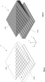
- FIG. 1a shows a simplified perspective view of a test specimen R according to the invention.
- the test specimen R comprises a profile block A, which is formed from a first material M A and extends in a longitudinal direction X, a transverse direction Y and a vertical direction Z.
- a stepped counter-block B made of a second material M B is arranged in the Z-direction below the profile block A. Large areas of the profile block A lie in the Z-direction above the counter-block B. An X-ray beam directed in the Z-direction from above through the profile block A therefore first penetrates the profile block A and then also the counter-block B below.
- Figure 1b shows the same arrangement as Figure 1a , where the two blocks A, B are highlighted in color to clarify the perspective arrangement.
- Figure 2a shows in a perspective arrangement already from the Figures 1a and 1b known combination of the profile block A with the counter-block B, with the profile block resting directly and almost completely on the counter-block.
- FIG 3 shows the matrix system according to which a test body according to the invention is constructed.
- Each segment S xy is denoted by its X and Y coordinates x,y.
- the coordinates are entered as examples, and the segments S 7.2 and S 2.5 are given for clarification.
- the tread block A extends from a top O A to a bottom U A (see figure 4 ).
- the bottom U A is bounded below by a minimum level H min , while the top is at a maximum level H max .
- Each segment of the profile block A extends from a segment-related underside height HU xy to a segment-related top side height HO xy and forms the thickness D xy of the segment in between.
- the thickness of the tread block A increases as the x coordinate increases increases in each case and reaches the maximum height H max of the profile block in segment S 10.1 .
- the respective thickness of the profile block A does not change in the Y-direction as long as the maximum height H max of the profile block A has not been reached. In the area below the maximum height, the thickness therefore only depends on the X position.
- the top side height HO xy increases with increasing Y coordinate
- the bottom side height HU xy also increases by the same amount, and therefore the thickness D xy remains constant within the same Y coordinate.
- the bottom height HU xy does not change as the X coordinate increases. This creates the surface O A in the manner of a two-dimensional ascending staircase, while the underside U A has a simple staircase shape.
- the inside figure 3 counter-block B arranged below the profile block A also extends in the X and Y direction and is designed as a staircase with individual steps T y . These extend from a common underside U B in the Z direction to a different step height for each Y coordinate with an individual step thickness DT y . Some of such steps and step thicknesses are given in figure 3 designated.
- the width of a step in the Y-direction corresponds to the width of the segments of the tread block A. This shape of the underside UA of the tread block and the top OB of the counter-block allows the respective surfaces of the two blocks to nestle against one another with almost no gap when they - be placed on top of each other ( figure 2a, figure 2b ).
- the arrangement of the profile block and the counter-block shown forms the combination of different material thicknesses of the two blocks in an XY matrix in a compact design. If you transport the specimen, for example in the X-direction, through an X-ray fan, for example, the specimen parallel to the Y-direction penetrates, all relevant thickness combinations can be radiographed in a short time and without the arrangement of profile block and counter-block having to be changed relative to each other, and the respective common radiographic properties can be recorded individually for each segment by a detector (line or area sensor) that is not shown in detail process, store or forward it via a suitable data processing device.
- a detector line or area sensor
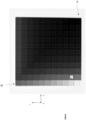
- figure 5 shows the result of a radiograph of a test specimen according to the invention with a projection of both the profile block and the counter-block.
- the segment S 1.1 is labeled for orientation. It can be seen that the intensity of the X-ray beam reaching the detector decreases with increasing X and Y coordinates, since the total thickness of the specimen increases in this direction as long as the maximum height is not yet reached.
- the thickness of tread block A no longer increases for segments whose sum of coordinates (x+y) is greater than 11
- the step thickness DT y of the counter block B is also constant in the X direction
- the gray values for all segments with (x + y) > 11 are constant with increasing X coordinates figure 5
- the outlined areas indicated represent those areas which, if necessary, are used to evaluate the radiation. With the formation of mean values, are used in order to be able to reliably rule out possible influences from adjacent segments with different thicknesses.
Landscapes
- Physics & Mathematics (AREA)
- Health & Medical Sciences (AREA)
- General Physics & Mathematics (AREA)
- Chemical & Material Sciences (AREA)
- Life Sciences & Earth Sciences (AREA)
- Analytical Chemistry (AREA)
- Biochemistry (AREA)
- General Health & Medical Sciences (AREA)
- Immunology (AREA)
- Pathology (AREA)
- Toxicology (AREA)
- Electromagnetism (AREA)
- Analysing Materials By The Use Of Radiation (AREA)
Description
- Die vorliegende Erfindung betrifft einen Prüfkörper zur Durchstrahlung mittels elektromagnetischer Strahlen, vorzugsweise Röntgenstrahlen. Der Prüfkörper dient zur Bestimmung von Referenzwerten, welche die Durchstrahlungseigenschaften eines Materials und insbesondere einer Paarung unterschiedlicher Materialien beschreiben.
- Bei der industriellen Fertigung von Produkten, insbesondere Lebensmitteln, ist häufig eine Untersuchung der Produkte auf unerwünschte Fremdkörper oder Verunreinigungen erforderlich, oder der Anteil bzw. die Dicke eines bestimmten Materials B an einer bestimmten Position innerhalb, oberhalb oder unterhalb des Materials A des Produktes ist zu ermitteln. Beispielsweise soll festgestellt werden, ob oder in welchem Anteil ein Stück Fleisch (als Material A) an einer bestimmten Position Knochen oder Fett (als Material B) aufweist. Das Produkt lässt sich dazu mittels Röntgenstrahlen durchstrahlen, wobei grundsätzlich auch jede andere zur Durchstrahlung geeignete Energieform Verwendung finden kann, etwa Terahertzstrahlung. Die verbleibende Intensität der aus dem durchstrahlten Produkt austretenden Röntgenstrahlen wird über einen Detektor (Zeilen- oder Flächensensor) erfasst und in einen der Intensität entsprechenden sogenannten "Grauwert" gewandelt. Dieser ist dann charakteristisch für eine bestimmte Dicke eines allein durchstrahlten Materials oder für eine Kombination des Materials A in einer bestimmten Dicke mit dem Material B in einer bestimmten Dicke (welche sich von der Dicke des Materials A auch unterscheiden kann)
- Um aus dem im laufenden Betrieb gemessenen Grauwert die korrekte Dicke des Materials oder der miteinander kombinierten Materialien zuordnen zu können muss zuvor für jede infrage kommende Materialdicke bzw. für jede Paarung zweier unterschiedlicher Materialien in jeweils verschiedenen Dicken der zugehörige Grauwert ermittelt bzw. simuliert und zur Zuordnung in einer geeigneten Datenverarbeitungsvorrichtung, beispielsweise in Tabellenform, hinterlegt werden (Anlernphase) Da hierbei Zuordnungen festgelegt werden, kann auch von Justieren gesprochen werden und der Prüfkörper könnte auch die Bezeichnung "Justierkörper" tragen. Für einen im regulären Betrieb gemessenen Grauwert lässt sich dann die Dicke des reinen Materials oder der in Strahlungsrichtung hintereinander liegenden Materialien anhand der Tabelle ermitteln. Zur Simulation der Durchstrahlungseigenschaften werden nach bisheriger Praxis die beiden infrage kommenden Materialien nacheinander in unterschiedlichen Dicken übereinandergelegt und jeweils durchstrahlt, um den zugehörigen Grauwert zu ermitteln und hinterlegen zu können (bevorzugt werden hier nicht die Materialien selbst sondern Ersatzmaterialien verwendet, welche die gleichen oder ähnliche Durchstrahlungseigenschaften besitzen, dauerhaft haltbar und gut bearbeitbar sind). Die Erstellung einer alle relevanten Dickenkombinationen enthaltenden Grauwerttabelle auf diese Weise ist sehr zeitaufwendig, und auch die Bereitstellung jedes Ersatzmaterials in unterschiedlichen Dicken ist aufwendig.
- Aus der
US 6 570 955 B1 ist ein Prüfkörper zur Durchstrahlung mittels Röntgenstrahlen bekannt, bei dem in einer Vielzahl von Segmenten jeweils wenigstens zwei unterschiedliche Materialien in einer Durchstrahlungsrichtung miteinander kombiniert sind, um aus der jeweiligen Durchstrahlung Referenzwerte für in der Praxis auftretende vergleichbare Materialpaarungen zu ermitteln. Die sich ergebenden Gesamtdicken der einzelnen Segmente sind jedoch für eine zügige Auswertung unhandlich, was zu einer unförmigen Gestaltung des gesamten Prüfkörpers führt. - Aufgabe der Erfindung war es daher, eine Vorrichtung und ein Verfahren anzubieten, um für eine Vielzahl möglicher Kombinationen von zwei oder auch mehr verschiedenen Materialien in jeweils wählbarer Dicke unter geringem zeitlichen und konstruktiven Aufwand jeweils einen Referenzwert (Grauwert) erfassen zu können.
- Die Aufgabe wird gelöst durch einen Prüfkörper nach Anspruch 1, eine Röntgeninspektionsvorrichtung nach Anspruch 14 und ein Verfahren nach Anspruch 16.
- Die Erfindung beruht auf der Erkenntnis, die Kombination wenigstens zweier Materialien in jeweils variierende Dicke ermöglichen zu können mittels eines speziellen Profilblocks, der aus einem der Materialien gebildet ist. Der Profilblock ist im wesentlichen zweidimensional in einer ersten horizontalen Längsrichtung X- und einer dazu rechtwinkligen, ebenfalls horizontalen Querrichtung Y ausgebildet ist. Die zu beiden Richtungen X, Y senkrechte dritte Richtung Z ist dabei zugleich die Richtung der Dicke Der Profilblock ist aus einem ersten Material MA gefertigt, welches die gleichen oder sehr ähnliche Durchstrahlungseigenschaften aufweist wie ein im Produktionsbetrieb zu untersuchendes Produktmaterial. Der Profilblock kann dazu monolithisch ausgebildet sein. Der Profilblock wird kombiniert mit einem Gegenblock aus einem zweiten Material MB, welches die gleichen oder sehr ähnliche Durchstrahlungseigenschaften aufweist wie das im laufenden Betrieb zu untersuchende zweite Material. Erfindungsgemäß erfolgt die Kombination, indem der Profilblock und der Gegenblock in Z-Richtung bzw. in Durchstrahlungsrichtung über- oder untereinander angeordnet und gemeinsam durchstrahlt werden. Zweckmäßigerweise sind die Durchstrahlungseigenschaften des Material MA des Profilblocks bezüglich Röntgenstrahlen verschieden von denjenigen des Materials MB des Gegenblocks B.
- Profilblock und Gegenblock bilden gemeinsam einen erfindungsgemäßen Prüfkörper. Die Erfindung sieht vor, dass der Profilblock in einer X-Y-Matrix Segmente Sxy mit jeweils konstanter Dicke Dxy in Z-Richtung aufweist. Jedes Segment ist durch seine jeweilige X- und Y-Koordinate (x, y) identifizierbar und in einem in einer X-Y-Ebene liegenden Segmentbereich in Z-Richtung durchstrahlbar. In X-Richtung ist eine Anzahl von n Segmenten und in Y-Richtung eine Anzahl von k Segmenten vorgesehen, wobei n und k jeweils größer sind als eins. Jedes Segment erstreckt sich in Z-Richtung von einer Oberseite Oxy , die auf einer Oberseitenhöhe HOxy liegt, bis zu einer Unterseite Uxy , die auf einer Unterseitenhöhe HUxy liegt, und bildet dadurch die Dicke Dxy aus. Der Profilblock (genauer: seine zur Durchstrahlung vorgesehenen Segmentbereiche) erstrecken sich in Z-Richtung zwischen einem Basisniveau Hmin, welches den Mindestwert für jede Unterseitenhöhe HUxy bildet, und einem Maximalniveau Hmax, welches den Maximalwert für jede Oberseitenhöhe HOxy bildet.
- Die der Erfindung zugrunde liegende Idee beruht darauf, den Profilblock in der Längsrrichtung (X-Richtung) mit segmentweise zunehmender Dicke auszubilden, wobei die Dicke vorzugsweise jeweils um einen konstanten Wert zunimmt. In der zur X-Richtung orthogonal Querrichtung (Y-Richtung) bleibt die durch die jeweilige X-Koordinate vorgegebene Dicke hingegen unabhängig von der Y-Koordinate konstant. Erfindungsgemäß ändert sich jedoch in Abhängigkeit der Y-Koordinate die Höhenlage des jeweiligen Segments. Vorzugsweise ändert sich die Höhenlage mit zunehmender Y-Koordinate jeweils um einen konstanten Wert. Der Profilblock erhält dadurch auf seiner Oberseite die Gestalt einer Treppe, welche in zunehmender X-und Y-Richtung jeweils ansteigt. Die Unterseite hingegen ist komplementär zu einer Treppe ausgebildet, deren Stufen in X-Richtung eine konstante Höhe aufweisen, während die Höhe der Unterseite in Y-Richtung mit jeder Stufe zunimmt.
- Der Profilblock aus dem Material Ma, ist somit in Z-Richtung - beispielsweise durch Aufeinanderlegen - kombinierbar mit einem Gegenblock aus dem Material MB, dessen Oberseite OB in Gestalt einer komplementär zur Unterseite des Profilblocks ausgebildeten Treppe geformt ist, wobei die Positiondes Profilblocks relativ zum Gegenblock als Prüfanordnung bezeichnet sein soll. Ist der Gegenblock dabei so gestaltet, dass die Dicke jeder Stufe mit zunehmender Y-Koordinate zunimmt, so ergibt sich für die einzelnen Segmente in der X-Y-Matrix des Profilblocks mit darunterliegendem Gegenblock jeweils eine Kombination des Materials Ma, in einer in X-Richtung zunehmenden und in Y-Richtung konstanten Dicke mit dem Material MB in einer in X-Richtung konstanten und in Y-Richtung zunehmenden Dicke. Eine Vielzahl von Materialkombinationen unterschiedlicher Dicke lässt sich so auf relativ geringem Raum herstellen, ohne dass die Prüfanordnung geändert werden muss. Der Begriff "Segment" umfasst bei einer Kombination von Profilblock mit Gegenblock das Material bzw. die Materialkombination, die sich an der durch die Segmentkoordinaten bestimmten Position in Z-Richtung insgesamt ergibt.
- Die Prüfanordnung, d.h. die Position des Profilblocks relativ zum Gegenblock, ist je nach Anforderung vorgebbar. Die beiden Blöcke können sich unmittelbar aneinander anschmiegen, in Z-Richtung beabstandet zueinander positioniert werden oder quer dazu um eine oder mehrere Segmentbreiten versetzt angeordnet sein.
- Hinweis: Die Durchstrahlungseigenschaften eines Materials ändern sich üblicherweise in Abhängigkeit der Materialdicke. Die Kombination unterschiedlicher Materialdicken dient erfindungsgemäß dazu, die dickenabhängigen Durchstrahlungseigenschaften zweier Materialien zu kombinieren. Vor diesem Hintergrund ist die in dieser Anmeldung beschriebene Kombination unterschiedlicher Dicken oder unterschiedlicher Materialien zu verstehen als Kombination unterschiedlicher Durchstrahlungseigenschaften (genauer : Absorptionseigenschaften) verschiedener Materialien.
- Der aus dem Profilblock und dem Gegenblock gebildete Prüfkörper kann dann in der Anlernphase, beispielsweise in X-Richtung, durch einen sich quer dazu erstreckenden Röntgenstrahlfächer hindurch gefahren werden, wobei die durch jedes Segment in Z-Richtung hindurchtretenden Röntgenstrahlen von einem darunter liegenden Detektor segmentbezogen erfasst und zumindest hinsichtlich ihrer verbleibenden Intensität ausgewertet werden. Anders als im Stand der Technik müssen die Materialien zur Überlagerung verschiedener Dicken des ersten Materials mit verschiedenen Dicken des zweiten Materials nicht mehr relativ zueinander bewegt werden, um jede gewünschte Dickenkombinationen zeitlich nacheinander zu erfassen, da alle relevanten Kombinationen durch den als Matrix gestalteten Prüfkörper bereits fertig ausgebildet sind. Die Durchstrahlung der einzelnen Segmente und die Erfassung, Auswertung und Hinterlegung der jeweiligen Grauwerte in einer Steuer- bzw. Datenverarbeitungseinheit kann daher zügig und in einer einzigen Relativposition von Profilblock und Gegenblock zueinander erfolgen.
- Der vorteilhafte Unterschied zum Stand der Technik ist offensichtlich. Bisher wurden einzelne Materialpaarungen (in Z-Richtung übereinanderliegend) jeweils in nur in einer Richtung, beispielsweise der Längsrichtung X, hintereinander liegend angeordnet. Um alle gewünschten Dickenpaarungen so hintereinanderliegend auszubilden ist ein sehr langer und unhandlicher Prüfkörper erforderlich, der daher nicht parallel zum Röntgenstrahlfächer (quer zur Fördereinrichtung) durch diesen hindurch bewegt werden kann (oder die einzelnen Paarungen sind aufgrund der begrenzten Detektorbreite quer zur Fördereinrichtung zu kurz, um einen zuverlässigen Absorptionswert ermitteln zu können). Erstreckt sich die Längsrichtung X des Prüfkörpers daher bei der Durchstrahlung in Förderrichtung und nicht quer dazu, dauert die Durchstrahlung sämtlicher einzelnen Dickenpaarungen unverhältnismäßig lange. Der erfindungsgemäße Prüfkörper dagegen bietet auf geringer horizontaler Fläche zweidimensional eine Vielzahl unterschiedlicher Dickenkombinationen und aufgrund der kompakten Ausbildung kann die X- bzw. Y-Achse des Prüfkörpers in der Anlernphase rechtwinklig oder parallel oder auch unter einem frei wählbaren Winkel zum Röntgenstrahlfächer ausgerichtet sein, und die schnelle Erfassung aller Dickenkombinationen ist dennoch einfach möglich.
- Jedes Segment des Profilblocks hat eine Oberseitenhöhe HOxy. Die Oberseitenhöhe nimmt in X-Richtung und in Y-Richtung jeweils segmentweise zu, sodass die Segmente insgesamt eine Anzahl f unterschiedlicher Oberseitenhöhen bilden. Ein Profilblock mit einer 10 x 10 - Segmentmatrix würde beispielsweise 100 Segmente mit 19 verschiedenen Oberseitenhöhen ausbilden. Eine Begrenzung der maximalen Höhe des Profilblocks, beispielsweise auf das Niveau der Oberseite des Segments mit den Koordinaten x=10, y=1, kann jedoch zweckmäßig sein und würde dazu führen, dass alle Segmente, deren Koordinatensumme (x+y) größer ist als 10, die gleiche Oberseitenhöhe HOxy = Hmax aufweisen (siehe
Fig. 1 ). Für Segmente mit (x+y) > 10 nimmt in diesem Fall die Dicke des Profilblocks mit zunehmender Y-Koordinate wieder ab und bleibt bei zunehmender X-Koordinate konstant. Die Begrenzung kann auf jedem gewünschten Niveau liegen. - Erfindungsgemäß ist der Profilblock so ausgebildet, dass für wenigstens vier, vorzugsweise alle Segmente die Oberseitenhöhe HOxy mit zunehmendem x-Index und mit zunehmendem y-Index zunimmt bis höchstens auf das Maximalniveau (Hmax), während die Unterseitenhöhe (HUxy) mit zunehmendem x-Index konstant bleibt und mit zunehmendem y-Index zunimmt.
- Ein solcher Profilblock aus einem ersten Material Ma, ist mithilfe eines geeigneten Gegenblocks aus einem zweiten Material zu einem erfindungsgemäßen Prüfkörper gemäß Anspruch 1 kombinierbar. Profilblock und Gegenblock erstrecken sich dabei in einer Längsrrichtung (X), einer dazu rechtwinklig verlaufenden Querrichtung (Y) und einer zu den beiden Richtungen (X, Y) senkrecht verlaufenden Höhenrichtung (Z).
- Der Profilblock weist eine Anzahl von Bereichen mit in Z-Richtung unterschiedlicher Dicke DA1, DA2, ... auf ebenso wie der Gegenblock, der eine Anzahl von Bereichen mit in Z-Richtung unterschiedlicher Dicke (DB1, DB2, ...) aufweist. Profilblock und Gegenblock sind in einer vorgebbaren Prüfanordnung in Z-Richtung übereinander anordenbar, um gemeinsam in Z-Richtung durchstrahlbare, voneinander verschiedene Materialpaarungen zu bilden. Erfindungsgemäß sind dabei in der Prüfanordnung wenigstens zwei, vorzugsweise alle verschiedenen, Dicken DA1, DA2,... des Profilblocks jeweils mit wenigstens zwei, vorzugsweise allen verschiedenen Dicken DB1, DB2... kombiniert. Zu jeder einzelnen im Profilblock vorhandenen Dicke gibt es daher jeweils eine Kombination mit jeder einzelnen im Gegenblock gebildeten Dicke, sodass Materialpaarungen entstehen in folgender Systematik:
DA1-DB1; DA1-DB2; DA1-DB3... DA2-DB1; DA2-DB2; DA2-DB3... usw. - Die Erfindung sieht vor, dass die Dicken des Profilblocks und des Gegenblocks so gewählt sind, dass der Prüfkörper mehrere Segmente aufweist, bei denen die Kombination verschiedener Einzeldicken des Profilblocks mit verschiedenen Einzeldicken des Gegenblocks jeweils zu einer gleichen Gesamtdicke des Prüfkörpers führt. Diese Gesamtdicke entspräche beispielsweise der Dicke eines zu durchstrahlenden Fleischstückes (Fleisch: Material MA), wobei das Fleischstück daraufhin zu untersuchen ist, ob bzw. zu welchem Teil diese Gesamtdicke durch ein Stück Knochen (Knochen: Material MB) gebildet wird. Trotz gleicher Gesamtdicke ergeben sich unterschiedliche Grauwerte bzw. Absorptionseigenschaften je nachdem, welches Material in welcher Dicke innerhalb des untersuchten Bereichs des Fleischstückes vorliegt. In Kenntnis der Gesamtdicke des Fleischstückes können dann zunächst die in zuvor angelernten und in der Tabelle hinterlegten Grauwerte ausgewählt werden, die für diese Gesamtdicke simuliert wurden. Aus diesen Grauwerten ist dann derjenige auszuwählen, der dem gemessenen Grauwert am ehesten entspricht. Die diesem simulierten Grauwert zugehörige Materialpaarung lässt sich dann aus der hinterlegten Tabelle bestimmen.
- Erfindungsgemäß sind zwei Segmente gleicher Gesamtdicke im Prüfkörper diagonal zueinander benachbart mit der Maßgabe, dass die Summe ihrer Koordinaten konstant ist (x + y = const.). Bereiche gleicher Gesamtdicke erstrecken sich dann bei einem Prüfkörper mit etwa quadratischen oder rechteckigen Segmenten in diagonaler Richtung (Siehe bspw.
Fig. 2a ). - Nach einer vorteilhaften Ausführungsform der Erfindung ändert sich die Dicke des Profilblocks mit zunehmendem x-Index um einen konstanten Wert. Die zu durchstrahlende Dicke des Profilblocks ändert sich mit zunehmender X-Koordinate dann linear. Dies ist zweckmäßig, wenn sich die Durchstrahlungseigenschaft des Materials beziehungsweise die Strahlungsintensität eines durch den Profilblock gerichteten und danach vom Detektor erfassten Röntgenstrahls linear zur Dicke verhält. Denkbar ist jedoch auch eine Variante, bei der die Änderung der Dicke zum in X-Richtung jeweils benachbarten Segment einer anderen, nichtlinearen mathematischen Bedingung gehorcht. So könnte beispielsweise ein bestimmter Kunststoff oder ein Metall Röntgenstrahlen über -oder unterproportional zur jeweils durchstrahlten Dicke absorbieren. Durch Anpassung der einzelnen Dicken an diesen nichtlinearen Zusammenhang der Absorption könnte sichergestellt werden, dass die Strahlungsabsorption bzw. die Strahlungsintensität des erfassten Röntgenstrahls mit zunehmender X- oder Y-Koordinate dann trotzdem stufenweise linear ab- oder zunimmt.
- Der erfindungsgemäße Profilblock erhält seine charakteristische Form durch die Vorgabe, dass sich die Dicke in X-Richtung segmentweise ändert, in Y-Richtung jedoch konstant bleibt (abgesehen von Begrenzungen die durch eine maximale Bauhöhe vorgegeben sind). Durch diese Vorgabe lässt sich der Profilblock mit einem treppenartigen Gegenblock so in Z-Richtung übereinander anordnen, dass in einer X-Y-Matrix die unterschiedlichen Dicken des Profilblocks jeweils mit den unterschiedlichen Dicken des Gegenblocks kombiniert werden. Auf vergleichsweise engem Raum lässt sich damit eine Vielzahl unterschiedlicher Dickenkombinationen erreichen, ohne dass Profilblock und Gegenblock dabei relativ zueinander bewegt werden müssen. Erfindungsgemäß kann der Prüfkörper segmentweise auf engem Raum die Parameter
- Dicke der Profilblocks
- Dicke des Gegenblocks, und
- Gesamtdicke des Prüfkörpers
- Der erfindungsgemäße Profilblock umfasst oberhalb des Basisniveaus eine mit "f" bezeichnete Anzahl unterschiedlicher Oberseitenhöhen. Die Oberseite jedes Segments bildet dabei jeweils eine Oberseitenhöhe, wobei mehrere Segmente die gleiche Oberseitenhöhe aufweisen können. Wie unter anderem
Figur 1a offenbart, liegt dies daran, dass die Oberseitenhöhe eines Segments bestimmt wird einerseits durch die Dicke des Profilblocks an diesem Segment und andererseits durch die Unterseitenhöhe, also das Höhenniveau, von dem sich das jeweilige Segment in Z-Richtung aufwärts erstreckt. Da erfindungsgemäß beides variiert, ergeben sich mehrere Segmente mit gleicher Oberseitenhöhe dann, wenn die Unterseitenhöhe in Y-Richtung im gleichen Maße ansteigt wie die Dicke in X-Richtung. - Die Oberseite des erfindungsgemäßen Profilblocks zeichnet sich dadurch aus, dass - ausgehend von einem Ausgangssegment - die Oberseitenhöhe sowohl des Nachbarsegments mit dem nächsthöheren X-Index als auch desjenigen mit dem nächsthöheren Y-Index zunimmt, solange eine vorgegebene Maximalhöhe Hmax diesen Zuwachs nicht begrenzt. Der Höhenunterschied in Z-Richtung von einem Ausgangssegment auf ein in X-Richtung oder in Y-Richtung angrenzendes, höher liegendes Nachbarsegment kann auch als Profilblockstufe bezeichnet werden. Bei einem Profilblock mit n in X-Richtung aneinandergrenzenden Segmenten und k in Y-Richtung aneinandergrenzenden Segmenten ergibt sich die Gesamtzahl f unterschiedlicher Oberseitenhöhen bzw. Profilblockstufen nach der Formel

- Der in
Figur 1a gezeigte Profilblock mit n=10 und k=10 hätte bei in der Höhe unbegrenzter Ausbildung 100 Segmente mit f=19 verschiedenen Oberseitenhöhen. Aus konstruktiven Gründen kann der Profilblock jedoch auch auf eine Höhe bzw. eine Anzahl Profilblockstufen begrenzt werden, oberhalb derer in der Matrix keine zusätzlichen Oberseitenhöhen mehr ausgebildet sind. Der Profilblock gemäßFigur 1a beispielsweise ist begrenzt auf eine maximale Höhe Hmax, die von den Oberseitenhöhen derjenigen Segmente bestimmt wird, für deren Koordinaten gilt (x + y) = 11. - Die Dicke (Dxy) eines Segments im Profilblock (A) folgt vorzugsweise aus der Bedingung Dxy = HOxy - HUxy, wobei für eine Gruppe von wenigstens vier Segmente gilt:


- Vorzugsweise gilt der vorgenannte Zusammenhang mindestens für alle Segmente mit der Koordinate x=1 oder y=1. Eine maximale Höhe Hmax ist erst dann erreicht, wenn der Profilblock für y=1 in X-Richtung bzw. für x=1 in Y-Richtung n bzw. k verschiedene Oberseitenhöhen ausgebildet hat.
- So folgt für den in
Figur 1a gezeigten Profilblock mit begrenzter Zahl an Profilblockstufen (f = 10) die Oberseitenhöhe HO2,7 für das Segment S2,7 unter der beispielhaften Annahme Hmax = 10, Hmin = 0:
- Der vollständig ausgebildete Profilblock (nach dem Vorbild der
Figur 1a , jedoch mit voller Profilblockstufenzahl f=19) hätte entsprechend die maximale Höhe Hmax=19, sodass sich für das Segment S2,7 die Oberseitenhöhe wieder ergäbe zu:
- und die Oberseitenhöhe des beispielhaft gewählten Segments S7,8 ergäbe sich zu :

- Nach einer vorteilhaften Ausführungsform weist jedes Segment einen Bereich mit einer gewissen Mindestausdehnung in X-und Y-Richtung auf, um für die vom Detektor erfassten Intensitäten der durch dieses Segment hindurch gerichteten Röntgenstrahlen einen repräsentativen Mittelwert bilden zu können. Vorzugsweise betragen die horizontalen Abmessungen jedes Segments oder zumindest des für die Durchstrahlung im Segment vorgesehenen Bereiches zwischen 40mm x 40mm, höchst vorzugsweise 20mm x 20mm, noch bevorzugter mehr als 5mm x 5mm.
- Die in den Figurenbeispielen gezeigten Ausführungsformen des Profilblocks zeigen Segmente, die in horizontaler Richtung im Wesentlichen quadratische Gestalt haben. Denkbar ist jedoch eine beliebige Ausführungsform, bei der die Segmente zum Beispiel rund oder rechteckig ausgebildet sind, also in eine der beiden horizontalen Richtungen eine größere Ausdehnung haben als in der jeweils anderen horizontaler Richtung. Dies kann zweckmäßig sein, um einen besseren Mittelwert bilden zu können bezogen auf die längere der beiden Abmessungen. Vorzugsweise weisen einige oder alle Segmente (Sxy) eine im Wesentlichen ebene Unterseite (Uxy) und/oder Oberseite Oxy senkrecht zur Z-Richtung auf.
- Der Gegenblock, der zur Ausbildung des Prüfkörpers mit dem Profilblock kombiniert wird, ist aus einem Material MB gefertigt, welches sich in wenigstens einer Eigenschaft vom Material MA des Profilblocks unterscheidet. Der Eigenschaftsunterschied sollte zweckmäßigerweise durch Röntgenstrahlen detektierbar sein. Der Unterschied kann allgemein die Absorptionseigenschaften des Materials bezüglich Röntgenstrahlen betreffen. Denkbar ist jedoch auch ein Unterschied im Wellenlängenspektrum eines durch das Material gerichteten Röntgenstrahls. Auch jede sonstige Materialeigenschaft, die durch Untersuchung eines durch das Material hindurch gerichteten elektromagnetischen Strahls (Röntgenstrahl, Terrahertz-Strahlung etc.) erfassbar ist, kann als Unterscheidungskriterium zwischen Material MA und MB herangezogen werden.
- Vorzugsweise ist der Gegenblock monolithisch, also aus einem durchgehenden Körper hergestellt. Schwierig zu untersuchenden Stoßstellen und zusätzlicher Montageaufwand werden dadurch vermieden.
- Zweckmäßigerweise ist der Gegenblock mit einer treppenförmige Oberseite ausgebildet und umfasst eine Anzahl m von in Y-Richtung hintereinander liegenden Stufen Ty unterschiedlicher Materialdicke. Die Stufen sind in Z-Richtung durchstrahlbar und ihre jeweils von der Y-Position abhängige Dicke DTy ist in X-Richtung vorzugsweise konstant.
- Vorzugsweise ist die Oberseite des Gegenblocks komplementär zur Unterseite des Profilblocks geformt. Da für jede der Stufen des Gegenblocks die Unterseitenhöhe der Segmente des Profilblocks in X-Richtung konstant ist, lässt sich der Profilblock bevorzugt von oben auf den Gegenblock aufsetzen, sodass die Oberseite des Gegenblocks bzw. seiner einzelnen Stufen Ty an der in X-Richtung in konstanter Höhe verlaufenden Unterseite des Profilblocks anliegen kann. So ergibt sich in kompakter Bauweise in einer X-Y-Matrix im Bereich jedes Segments Sxy die Kombination zweier unterschiedlicher Materialien in Z-Richtung, um diese gemeinsam zu durchstrahlen.
- Alternativ kann der Gegenblock auch in Z-Richtung beabstandet und/oder oberhalb des Profilblocks angeordnet werden. Die möglichst abstandslose Anordnung von Profilblock und Gegenblock ist jedoch zu bevorzugen, da das Winkelsegment eines Röntgenstrahlenfächers, welches innerhalb des Segments durch beide Blöcke gerichtet werden kann, , mit zunehmendem Abstand zwischen Profilblock und Gegenblock kleiner wird und die Bildung eines zuverlässigen Mittelwerts erschwert. Natürlich kann die Anordnung von oberem Profilblock mit darunter liegendem Gegenblock auch als Ganzes umgekehrt (auf den Kopf gestellt) werden. Unter Berücksichtigung der dann zu korrigierenden X- und Y-Richtungen bzw. -koordinaten ergeben sich für die einzelnen Segmente identische Durchstrahlungsverhältnisse in Z-Richtung.
- Damit Profilblock und Gegenblock möglichst komplementär zueinander ausgebildet sind, ist vorzugsweise vorgesehen, dass die Abmessung in Y-Richtung einer Treppenstufe Ty derjenigen Y-Abmessung eines Segmentes Sxy des Profilblocks entspricht.
- Die unterschiedlichen Dicken des Gegenblocks, die mit den unterschiedlichen Dicken des Profilblocks kombiniert werden sollen, ergeben sich aus den unterschiedlichen Stufenhöhen. Vorzugsweise erstreckt sich der Gegenblock daher von einer für alle Stufen gemeinsamen Unterseite bis auf eine für jede Stufe unterschiedliche Z-Höhe. Der Höhenunterschied zweier in Y-Richtung benachbarter Stufen entspricht vorzugsweise dem Dickenunterschied zweier in X-Richtung benachbarter Segmente des Profilblocks. Dadurch lassen sich die zuvor bereits beschriebenen unterschiedlichen Segmente mit gleicher Gesamtdicke ausbilden. Alternativ ist es jedoch denkbar, die Dicken oder Dickenänderung der in Y-Richtung hintereinander liegenden einzelnen Stufen unabhängig von der Dicke der Segmente des Profilblocks zu wählen. Insbesondere unter Berücksichtigung der Absorptionseigenschaften des Gegenblockmaterials kann es zweckmäßig sein, die Dicken oder deren Unterschied zweier benachbarter Stufen nach einem linearen oder nichtlinearen Zusammenhang zwischen Materialdicke und Absorptionseigenschaften zu wählen. Ähnlich wie für den Profilblock können so insbesondere nichtlineare Zusammenhänge zwischen Materialdicke und Absorptionseigenschaften in einen linearen Zusammenhang zwischen der jeweiligen Y-Position der Stufe und ihrer Strahlungsabsorption überführt werden.
- Obwohl die Materialpaarung des Profilblocks mit dem Gegenblock erfindungsgemäß von besonderem Interesse ist, soll der Prüfkörper auch die Möglichkeit bieten, in Z-Richtung nur einen der beiden Blöcke an unterschiedlichen Dickenpositionen zu durchstrahlen. So lassen sich die Absorptionseigenschaften des reinen Profilblockmaterials und/oder des reinen Gegenblockmaterials in der Prüfanordnung zusätzlich erfassen, das jeweils andere Material wäre in diesem Fall Luft.
- In einer vorteilhaften Ausführungsform der Erfindung ist daher vorgesehen, dass ein Abschnitt A0 des Profilblocks in X-Richtung oder in Y-Richtung in Form eines Überstands über den Gegenblock B seitlich hinausragt, so dass dort oberhalb oder unterhalb des Profilblocks A kein Abschnitt des Gegenblocks B, sondern bevorzugt das Material "Luft", angeordnet ist. In gleichem Sinne kann alternativ oder zusätzlich vorgesehen sein, dass ein Abschnitt B0 des Gegenblocks B in X-Richtung oder in Y-Richtung in Form eines Überstands über den Profilblock A seitlich hinausragt, so dass dort oberhalb oder unterhalb des Gegenblocks B kein Abschnitt des Profilblocks A, sondern bevorzugt Luft, angeordnet ist. Entsprechend zeigt
Figur 2a oder 2b , dass der Profilblock A den Gegenblock B in Y-Richtung mit dem Abschnitt A0 überragt, während zugleich der Gegenblock B in X-Richtung mit dem Abschnitt B0 unter dem Profilblock A hervorragt. Die den Überstand bildenden Segmente sind vorzugsweise etwa doppelt so breit wie die an den Überstand angrenzenden Segmente (so sind die den Überstand des Profilblocks inFigur 2a mit ausbildenden Segmente Sx,1 jeweils etwa doppelt so breit wie die in Y-Richtung angrenzenden Segmente Sx,2. ) Dadurch bieten diese Segmente einen Bereich mit Material des anderen Blocks darüber oder darunter sowie einen weiteren Bereich, der ausschließlich vom jeweiligen Block gebildet wird. - Nach einer vorteilhaften Ausführungsform ist weiterhin vorgesehen, dass oberhalb, unterhalb oder zwischen dem Profilblock A und dem Gegenblock B wenigstens ein aus einem dritten Material Mc gebildeter, vorzugsweise monolithischer Ergänzungsblock C, D,... angeordnet ist, um mehrere verschiedene, in Z-Richtung zu durchstrahlende Materialpaarungen zu erzeugen. Der Ergänzungsblock kann dabei eine für jedes Segment konstante Dicke oder stufenweise ansteigende Dicken aufweisen, um die Strahlungsabsorption der jeweiligen Segmente entsprechend zu beeinflussen. Denkbar ist jedoch auch, nur für eine Auswahl der Segmente deren vom Profilblock und vom Gegenblock gebildeten Durchstrahlungseigenschaften zusätzlich gezielt durch das Material Mc zu verändern, und auf andere Segmente keinen Einfluss zu nehmen. Beispielsweise könnte ab einer bestimmten Dicke des Gegenblocks B (der mit dem Material MB beispielsweise Knochen repräsentieren könnte) eine zusätzliche Materialschicht C in konstanter oder variabler Dicke in Z-Richtung über, unter oder zwischen den Blöcken A und B angeordnet werden, der beispielsweise eine ab einer gewissen Knochendicke stets auftretende Fettschicht repräsentieren könnte). Grundsätzlich lassen sich beliebig viele verschiedene Materialien in Z-Richtung übereinander anordnen. Zu bedenken ist jedoch, dass die für nur zwei Materialien erfindungsgemäß mögliche Kombination "jede Dicke des Profilblocks mit jeder Dicke des Gegenblocks" im dreidimensionalen Raum bei einer durch das zusätzliche Material C hinzukommenden weiteren "Dimension" nicht mehr ohne weiteres möglich ist.
- Im Bereich der Lebensmittelverarbeitung kann vorzugsweise vorgesehen sein, dass die Durchstrahlungseigenschaften des Materials des Profilblocks oder des Gegenblocks oder des Ergänzungsblocks bezüglich Röntgenstrahlen im Wesentlichen denjenigen entsprechen von wahlweise tierischem Fett, Wasser, Fleisch, Knochen, Glas, Metall oder Kunststoff. Je nach Anwendungsfall kann auch anderes Material verwendet werden, welches den Durchstrahlungseigenschaften eines zu untersuchenden Materials innerhalb vorgebbarer Toleranzen entspricht oder identisch zu diesem Material ist.
- Nach einer vorteilhaften Ausführungsform der Erfindung ist ferner vorgesehen, dass einer oder mehrere der Blöcke A, B, C... Kennzeichnungsmittel aufweisen, die vorzugsweise mittels Röntgenstrahlen detektierbar sind und/oder Information enthalten oder wenigstens einem der Blöcke zuordenbar machen. Dabei kann es sich um eine eindeutige Identifikation wenigstens eines der Blöcke handeln. Denkbar wäre etwa die Anordnung geeigneter metallischer Elemente oder Codierungen am oder im jeweiligen Block, um aus dem bei seiner Durchleuchtung entstehenden Röntgenbild Rückschlüsse auf die Art des Blocks ziehen zu können. Auch die räumliche Ausrichtung und/oder die Position eines Blocks kann auf diese Weise bestimmt werden. Dazu könnte der Block räumlich angeordnete Kennzeichnungselemente aufweisen (im einfachsten Fall sind dies kleine metallische Elemente wie beispielsweise . Kugeln). Die Auswertung des Röntgenbilds unter Zuhilfenahme trigonometrischer Grundsätze erlaubt dann (etwa unmittelbar vor der Anlernphase) die Überprüfung, ob die Blöcke relativ zueinander und/oder relativ zur Röntgenquelle korrekt positioniert sind. Fehlmessungen lassen sich so vermeiden. Schließlich können die Kennzeichnungsmittel auch zur Ermittlung von Kennwerten oder Korrekturwerten dienen, welche beispielsweise die Durchstrahlungseigenschaften eines bestimmten Blocks oder einzelner Segmente des Blocks oder des gesamten Prüfkörpers betreffen. Die Auswertung des Röntgenbilds zur Ermittlung der Lage, der Position oder der Kennwerte bzw. Korrekturwerte oder die Speicherung der die einzelnen Blöcke und Materialien identifizierenden Kennwerte kann computergestützt erfolgen, und davon abhängige Steuersignale zur Steuerung der Anlernphase (Abbruch, Neuausrichtung, Fördergeschwindigkeit etc.) können automatisch erzeugt werden.
- Der erfindungsgemäße Prüfkörper kann Bestandteil einer Röntgeninspektionsvorrichtung sein. Die Röntgeninspektionsvorrichtung kann natürlich auch mehrere verschiedene Prüfkörper, Profilblöcke und/oder Gegenblöcke aufweisen. Denkbar ist auch ein Sortiment von Profilblöcken und Gegenblöcken, bei dem ein Profilblock mit unterschiedlichen Gegenblöcken bzw. unterschiedliche Profilblöcke mit einem Gegenblock kombinierbar sind. So ließe sich beispielsweise ein das Material Fleisch repräsentierender Profilblock einmal mit einem Gegenblock kombinieren, der das Durchstrahlungsverhalten von Knochen aufweist, während eine Kombination des Profilblocks mit einem anderen Gegenblock die Paarung Fleisch - Fett simulieren würde.
- Die Matrixgröße eines erfindungsgemäßen Profilblocks, Gegenblocks, Ergänzungsblocks oder Prüfkörpers ist theoretisch nicht begrenzt. Sie nimmt zu mit der Anzahl der gewünschten Dickenkombinationen. Bereits eine in der X- und Y-Richtung aufgespannte 2 x 2-Segmentmatrix bietet den erfindungsgemäßen Vorteil, unterschiedliche Materialdicken platzsparend miteinander kombinieren zu können. Eine größere Matrix erlaubt entsprechend mehr Kombinationen, wobei je nach Anwendungsfall die Anzahl n der Segmente in X-Richtung verschieden sein kann von der Anzahl k der Segmente in Y-Richtung. Ein vollständig ausgebildeter 12x12-Prüfkörper bietet beispielsweise 144 Kombinationen, wobei ein durch den Profilblock und den Gegenblock jeweils zusätzlich gebildeter seitlicher Überstand nochmals 24 Kombinationen der Blöcke mit dem Material "Luft" hinzufügt.
- Bei der Durchstrahlung eines erfindungsgemäßen Prüfkörpers kann es zweckmäßig sein, zur Auswertung der Durchstrahlungseigenschaften jedes Segments nur diejenigen Strahlen heranzuziehen, die vom Rande des Segments einen gewissen Abstand haben. Der störende Einfluss von Dickensprüngen zu benachbarten Segmenten wird so bei der Auswertung oder Mittelwertbildung sicher ausgeschlossen.
- Die Bestandteile des erfindungsgemäßen Prüfkörpers (Profilblock, Gegenblock, Ergänzungsblock) können auf unterschiedliche Weise hergestellt werden. Infrage kommt unter anderem die Herstellung im 3D-Druck, durch Sintern, Fräsen, Pressen, Kleben, Gießen, Lasern, Erodieren, Ätzen oder Kombinationen daraus. Die Bestandteile können durch dem Fachmann bekannte Mechanismen erforderlichenfalls - auch dauerhaft - miteinander verbunden werden, etwa durch Kleben, Verschrauben, Verrasten, Verschweißen oder Kombinationen davon.
- Die vorliegende Erfindung wurde beschrieben anhand von Raumachsen mit zugehörigen Koordinaten x, y, z und Indizes für die einzelnen Segmente. Erfindungswesentlich ist jedoch nicht die Benennung oder auch die Ausrichtung der Raumachsen zueinander, sondern das Prinzip, einen Profilblock auszubilden, der in zwei voneinander verschiedenen Raumrichtungen X und Y jeweils Segmente mit unterschiedlicher Dicke und unterschiedlicher Höhe in Z-Richtung ausbildet. Aus konstruktiven Gründen bietet es sich an, die Dicke beispielsweise in X-Richtung mit zunehmendem X-Index stufenartig und um jeweils einen konstanten Wert anwachsen zu lassen, während die Oberseitenhöhe in Y-Richtung in gleicher Weise stufenartig zunimmt. Sofern konstruktiv möglich ist der erfindungsgemäße Profilblock jedoch nicht auf eine solche streng aufsteigende stufenartige Ausführungsform beschränkt. Der erfindungsgemäße Gedanke wird auch dann verwirklicht, wenn der Profilblock an beliebigen X-Y-Position einer zweidimensionalen Matrix wenigstens vier Segmente mit in einer dritten Dimension jeweils unterschiedlichen Dicken und unterschiedlichen Oberseitenhöhen aufweist, um jedes Segment in Z-Richtung mit einem Abschnitt des Gegenblocks bestimmter Dicke zu kombinieren und so möglichst alle Dicken-Kombinationen des Profilblocks mit dem Gegenblock zu ermöglichen.
- Nachfolgend soll eine Ausführungsform eines erfindungsgemäßen Prüfkörpers anhand von Figuren näher erläutert werden. Dabei zeigen
- Figuren 1a, 1b
- perspektivische Ansichten eines Profilblocks oberhalb eines Gegenblocks;
- Figuren 2a, 2b
- die Blöcke gemäß
Figuren 1a, 1b unmittelbar aufeinander liegend; - Figur 3
- die Darstellung der
Figur 1a mit weiteren Details; - Figur 4
- einen Profilblock mit weiteren Details, teilweise transparent dargestellt; und
- Figur 5
- das Durchstrahlungsergebnis eines erfindungsgemäßen Prüfkörpers.
-
Figur 1a zeigt eine vereinfachte perspektivische Darstellung eines erfindungsgemäßen Prüfkörpers R. Der Prüfkörper R umfasst einen Profilblock A, der aus einem ersten Material MA gebildet ist und sich in einer Längsrichtung X, einer Querrichtung Y sowie einer Höhenrichtung Z erstreckt. In Z-Richtung unterhalb des Profilblocks A ist ein treppenförmiger Gegenblock B aus einem zweiten Material MB angeordnet. Weite Bereiche des Profilblocks A liegen in Z-Richtung oberhalb des Gegenblocks B. Ein in Z-Richtung von oben durch den Profilblock A gerichteter Röntgenstrahl durchdringt daher zuerst den Profilblock A und danach auch den darunterliegenden Gegenblock B. -
Figur 1b zeigt die gleiche Anordnung wieFigur 1a , wobei die beiden Blöcke A, B farblich hervorgehoben sind, um die perspektivische Anordnung zu verdeutlichen. -
Figur 2a zeigt in perspektivische Anordnung die bereits aus denFiguren 1a und 1b bekannte Kombination des Profilblocks A mit dem Gegenblock B, wobei hier der Profilblock unmittelbar und nahezu abstandslos auf dem Gegenblock aufliegt. -
Figur 3 zeigt die Matrix-Systematik, nach der ein erfindungsgemäßer Prüfkörper aufgebaut ist. Der Profilblock A erstreckt sich in X-Richtung entlang einer Anzahl von n Segmenten Sxy, wobei in dieser Ausführungsform n=10 ist. In Y-Richtung ist der Profilblock A in eine Anzahl von k Segmenten aufgeteilt, wobei in dieser Ausführungsform k=10 gewählt ist. Jedes Segment Sxy wird durch seine X-und Y-Koordinate x, y, bezeichnet. So liegt etwa das Segment mit der Koordinate x=1 und y=1, welches dann mit "S1,1" bezeichnet würde, inFigur 1a im vordersten untersten Abschnitt des Profilblocks A. Für weitere Segmente sind die Koordinaten beispielhaft eingetragen, und die Segmente S7,2 sowie S2,5 sind zur Verdeutlichung angegeben. - Der Profilblock A erstreckt sich von einer Oberseite OA bis zu einer Unterseite UA (siehe
Figur 4 ). Die Unterseite UA ist nach unten begrenzt durch ein Mindestniveau Hmin, während die Oberseite auf einem Maximalniveau Hmax liegt. - Jedes Segment des Profilblocks A erstreckt sich von einer segmentbezogenen Unterseitenhöhe HUxy bis auf eine segmentbezogene Oberseitenhöhe HOxy und bildet dazwischen jeweils die Dicke Dxy des Segments aus. Wie insbesondere entlang der Koordinate y=1 zu sehen ist, nimmt die Dicke des Profilblocks A mit zunehmender X-Koordinate jeweils zu und erreicht im Segment S10,1 die maximale Höhe Hmax des Profilblocks. In Y-Richtung verändert sich die jeweilige Dicke des Profilblocks A nicht, solange die maximal Höhe Hmax des Profilblocks A nicht erreicht ist. Im Bereich unterhalb der maximalen Höhe hängt die Dicke daher nur von der X-Position ab. In Y-Richtung hingegen erhöht sich die Oberseitenhöhe HOxy mit zunehmender Y-Koordinate, während auch die Unterseitenhöhe HUxy jeweils um das gleiche Maß zunimmt, und daher die Dicke Dxy innerhalb der gleichen Y-Koordinate konstant bleibt. Die Unterseitenhöhe HUxy ändert sich mit zunehmender X-Koordinate nicht. Dadurch entsteht die Oberfläche OA nach Art einer zweidimensional aufsteigenden Treppe, während die Unterseite UA eine einfache Treppenform aufweist.
- Der in
Figur 3 unterhalb des Profilblocks A angeordnete Gegenblock B erstreckt sich ebenfalls in X- und Y-Richtung und ist als Treppe mit einzelnen Stufen Ty ausgebildet. Diese erstrecken sich von einer gemeinsamen Unterseite UB in Z-Richtung zu einer für jede Y-Koordinate verschiedenen Stufenhöhe mit einer individuellen Stufendicke DTy. Einige solcher Stufen und Stufendicken sind beispielhaft inFigur 3 bezeichnet. Die Breite einer Stufe in Y-Richtung entspricht hier jeweils der Breite der Segmente des Profilblocks A. Durch diese Formgebung der Unterseite UA des Profilblocks und der Oberseite OB des Gegenblocks können sich die jeweiligen Flächen der beiden Blöcke weitgehend abstandslos aneinander anschmiegen, wenn sie - aufeinander gelegt werden (Figur 2a, Figur 2b ). - In dieser (in
Figur 2 gezeigten) Anordnung ragt der Profilblock A mit einem Überstand A0 in Y-Richtung seitlich über den Gegenblock B hinaus. In diesem Bereich erfasst ein entlang der Z-Richtung durch den Prüfkörper gerichteter Röntgenstrahl nur das Material des Profilblocks A, während der Bereich unterhalb des Überstands als Material "Luft" gilt. In gleicher Weise ragt der Gegenblock mit einem Überstand B0 in X-Richtung seitlich unter dem Profilblock A hervor, sodass anstelle des Profilblockmaterials hier wiederum das Material "Luft" durchleuchtet würde. - Die unter anderem in
Figur 2a und 2b gezeigte Anordnung des Profilblocks und des Gegenblocks, die auch als Prüfanordnung bezeichnet wird, bildet erfindungsgemäß die Kombination unterschiedlicher Materialdicken der beiden Blöcke in einer X-Y-Matrix in kompakter Bauform. Transportiert man den Prüfkörper, beispielsweise in X-Richtung, durch einen Röntgenstrahlfächer, der den Prüfkörper beispielsweise parallel zur Y-Richtung durchdringt, so lassen sich in kurzer Zeit und ohne dass die Anordnung von Profilblock und Gegenblock relativ zueinander geändert werden müsste, alle relevanten Dickenkombinationen durchstrahlen und die jeweils gemeinsamen Durchstrahlungseigenschaften durch einen nicht näher gezeigten Detektor (Zeilen- oder Flächensensor) für jedes Segment individuell erfassen und über eine geeignete Datenverarbeitungsvorrichtung verarbeiten, abspeichern oder weiterleiten. -
Figur 5 zeigt das Ergebnis einer Durchstrahlung eines erfindungsgemäßen Prüfkörpers mit Überstand sowohl des Profilblocks als auch des Gegenblocks. Das Segment S1,1 ist zur Orientierung beschriftet. Zu sehen ist, dass die Intensität des den Detektor erreichende Röntgenstrahls mit zunehmender X- und Y-Koordinate abnimmt, da in dieser Richtung die Gesamtdicke des Prüfkörpers zunimmt, solange die maximale Höhe noch nicht erreicht ist. Da der Prüfkörper in dieser Ausführungsform auf die maximale Höhe des Segments S10,1 begrenzt ist (Hmax = HO10,1), nimmt die Dicke des Profilblocks A nicht mehr zu für Segmente, deren Koordinatensumme (x+y) größer ist als 11. Da auch die Stufendicke DTy des Gegenblocks B in X-Richtung konstant ist, sind die Grauwerte für alle Segmente mit (x + y) > 11 mit zunehmender X-Koordinate konstant.Die in den einzelnen Segmenten derFigur 5 angedeuteten umrandeten Bereiche stellen diejenigen Bereiche dar, die zur Auswertung der Durchstrahlung, ggfsl. Unter Bildung von Mittelwerten, herangezogen werden, um mögliche Einflüsse angrenzender Segmente mit abweichender Dicke sicher ausschließen zu können. -
- A
- Profilblock
- A0
- Abschnitt, Überstand des Profilblocks
- B
- Gegenblock
- B0
- Abschnitt, Überstand des Gegenbocks
- C, D
- Ergänzungsblock
- DA
- Eine Dicke des Profilblocks A
- DB
- Eine Dicke des Gegenblocks B
- Dxy
- Dicke des Segments Sxy
- f
- Anzahl unterschiedlicher Oberseitenhöhen
- Hmax
- Maximalniveau
- Hmin
- Basisniveau
- HOxy
- Oberseitenhöhe des Segments Sxy
- HUxy
- Unterseitenhöhe des Segments Sxy
- k
- Anzahl Segmente in Y-Richtung
- m
- Anzahl der Stufen T
- MA
- Material des Profilblocks A
- MB
- Material des Gegenblocks B
- n
- Anzahl Segmente in X-Richtung
- OA
- Oberseite des Profilblocks A
- OB
- Oberseite des Gegenblocks B
- R
- Prüfkörper
- Sxy
- Segment an der Position x, y
- Ty
- Stufe des Gegenblocks B an der Position y
- UA
- Unterseite des Profilblocks A
- UB
- Unterseite des Gegenblocks B
- x
- Index, X-Koordinate
- X
- Längsrichtung
- y
- Index, Y-Koordinate
- Y
- Querrichtung
- Z
- Höhenrichtung
Claims (18)
- Prüfkörper (R) für Röntgeninspektionsanlagen,a) umfassend einen aus einem ersten Material (MA) gebildeten, vorzugsweise monolithischen Profilblock (A) und einen vorzugsweise monolithischen Gegenblock (B), dessen Material (MB) sich in wenigstens einer Eigenschaft vom ersten Material (MA) unterscheidet, wobei sich der Profilblock (A) und der Gegenblock (B) in einer Längsrichtung (X), einer dazu rechtwinklig verlaufenden Querrichtung (Y) und einer zu den beiden Richtungen (X, Y) senkrecht verlaufenden Höhenrichtung (Z) erstrecken,b) wobei der Profilblock (A) eine Anzahl von Bereichen mit in Z-Richtung unterschiedlicher Dicke (DA1, DA2, ...) aufweist und wobei der Gegenblock (B) eine Anzahl von Bereichen mit in Z-Richtung unterschiedlicher Dicke (DB1, DB2, ...) aufweist,c) wobei der Profilblock (A) und der Gegenblock (B) in einer vorgebbaren Prüfanordnung in Z-Richtung übereinander anordenbar sind, um gemeinsam in Z-Richtung durchstrahlbare, voneinander verschiedene Materialpaarungen zu bilden,d) dass die Dicken des Profilblocks und des Gegenblocks in einer X-Y-Matrix miteinander kombiniert sind, indem in X-Richtung wenigstens zwei, vorzugsweise alle, verschiedenen Dicken des Profilblocks (A) mit einer Dicke des Gegenblocks (B) kombiniert sind, während in Y-Richtung wenigstens zwei, vorzugsweise alle verschiedenen Dicken des Gegenblocks (B) mit einer Dicke des Profilblocks (A) kombiniert sind
dadurch gekennzeichnet,e) dass die Prüfanordnung entlang von Diagonalen angeordnete Segmente gleicher Gesamtdicke mit jeweils unterschiedlichen einzelnen Dicken (DA, DB) bildet,f) wobei entlang jeder Diagonalen alle Segmente einer Diagonalen eine jeweils konstante Gesamtdicke aufweisen. - Prüfkörper nach Anspruch 1,a) wobei der Profilblock (A) eine Oberseite (OA) und eine Unterseite (UA) aufweist, undb) wobei der Profilblock (A) in einer X-Y-Matrix Segmente (Sxy) mit jeweils konstanter Dicke (Dxy) in Z-Richtung aufweist, die zu Prüfzwecken durchstrahlbar sind, wobei jedes Segment durch seine jeweilige X- und Y-Koordinate (x, y) identifizierbar ist, undc) wobei in X-Richtung eine Anzahl von (n) Segmente (Sxy) und in Y-Richtung eine Anzahl von (k) Segmenten (Sxy) mit (n >1, k >1) vorgesehen ist, undd) wobei sich jedes Segment (Sxy) in Z-Richtung von einer Oberseite mit einer zugehörigen Oberseitenhöhe (HOxy) bis zu einer Unterseite mit einer zugehörigen Unterseitenhöhe (HUxy) erstreckt und dadurch die Dicke (Dxy) ausbildet, unde) wobei sich die zur Durchstrahlung vorgesehenen Bereiche aller Segmente (Sxy) in Z-Richtung erstrecken zwischen einem Basisniveau (Hmin), welches den Mindestwert für jede Unterseitenhöhe (HUxy) bildet, und einem Maximalniveau (Hmax), welches den Maximalwert für jede Oberseitenhöhe (HOxy) bildet, undf) wobei der Profilblock (A) oberhalb des Basisniveaus (Hmin) Segmente (Sxy) mit einer Anzahl (f) unterschiedlicher Oberseitenhöhen (HOxy) aufweist,
dadurch gekennzeichnet,g) dass für wenigstens vier, vorzugsweise alle, Segmente (Sxy)g1) die Oberseitenhöhe (HOxy) mit zunehmendem x-Index und mit zunehmendem y-Index zunimmt bis höchstens auf das Maximalniveau (Hmax), undg2) die Unterseitenhöhe (HUxy) mit zunehmendem x-Index konstant bleibt und mit zunehmendem y-Index zunimmt. - Prüfkörper nach dem vorhergehenden Anspruch, dadurch gekennzeichnet, dass die Dickenänderung mit zunehmendem x-Index jeweils gleich ist.
- Prüfkörper nach Anspruch 2 oder 3, dadurch gekennzeichnet, dass die Dicke (Dxy) mit zunehmendem x-Index zunimmt und mit zunehmendem Y-Index konstant bleibt.
- Prüfkörper (A) nach einem der Ansprüche 1 bis 4, dadurch gekennzeichnet, dass die Dicke (Dxy) folgt aus der Bedingung Dxy = HOxy - HUxy, wobei für eine Gruppe von wenigstens vier, vorzugsweise für alle Segmente (Sxy) gilt:


- Prüfkörper nach einem der vorigen Ansprüche,a) wobei der Gegenblock (B) gebildet wird durch eine Anzahl (m) von in Y-Richtung hintereinanderliegenden, zu Prüfzwecken durchstrahlbaren Stufen (Ty) mit einer entlang der X-Richtung jeweils konstanten Stufendicke, (DTy) undb) wobei der Gegenblock (B) oberhalb oder unterhalb des Profilblocks (A) zu diesem in Höhenrichtung (Z) beabstandet oder abstandslos gegenüberliegt,um die beiden gepaarten Blöcke (A, B) im Bereich eines Segments (Sxy) gemeinsam in Z-Richtung zu durchstrahlen und für mehrere Segmente (Sxy) jeweils einen Wert erfassen zu können, der die gemeinsamen Durchstrahlungseigenschaften der beiden in diesen Segmenten (Sxy) übereinander liegenden Blöcke charakterisiert.
- Prüfkörper nach dem vorhergehenden Anspruch, dadurch gekennzeichnet, dass die Abmessung in Y-Richtung einer Treppenstufe (Ty) derjenigen Y-Abmessung eines Segmentes (Sxy) des Profilblocks (A) entspricht.
- Prüfkörper nach einem der vorigen Ansprüche, dadurch gekennzeichnet, dass sich jede Stufe (Ty) von einer im Wesentlichen ebenen, allen Stufen gemeinsamen Unterseite (UB) des Gegenblocks (B) bis auf eine für jede Stufe (Ty) unterschiedliche Höhe oberhalb der Unterseite (UB) erstreckt.
- Prüfkörper nach einem der vorigen Ansprüche, dadurch gekennzeichnet, dass ein Abschnitt (A0) des Profilblocks (A) in X-Richtung oder in Y-Richtung in Form eines Überstands über den Gegenblock (B) seitlich hinausragt, so dass dort oberhalb oder unterhalb des Profilblocks (A) kein Abschnitt des Gegenblocks (B) angeordnet ist.
- Prüfkörper nach einem der vorigen Ansprüche, dadurch gekennzeichnet, dass ein Abschnitt (B0) des Gegenblocks (B) in X-Richtung oder in Y-Richtung in Form eines Überstands über den Profilblock (A) seitlich hinausragt, so dass dort oberhalb oder unterhalb des Gegenblocks (B) kein Abschnitt des Profilblocks (A) angeordnet ist.
- Prüfkörper nach Anspruch 9 oder 10, dadurch gekennzeichnet, dass die Abmessung, um welches der Überstand über den jeweils anderen Block hinausragt, der in der gleichen Richtung zu messenden Abmessung eines an den Überstand angrenzenden Segments des anderen Blocks entspricht.
- Prüfkörper nach einem der vorigen Ansprüche, dadurch gekennzeichnet, dass der Profilblock (A) mit seiner Unterseite (UA) auf der Oberseite (OB) des Gegenblock (B) aufliegt.
- Prüfkörper nach einem der vorigen Ansprüche, dadurch gekennzeichnet, dass ein aus einem dritten Material (MC, MD) gebildeter, vorzugsweise monolithischer Ergänzungsblock (C, D, ...) vorgesehen ist, der in Z-Richtung oberhalb, unterhalb oder zwischen der Anordnung des Profilblocks und des Gegenblocks positioniert ist.
- Prüfkörper nach einem der vorigen Ansprüche, dadurch gekennzeichnet, dass einer oder mehrere der Blöcke (A, B, C, D...) Kennzeichnungsmittel aufweisen, die vorzugsweise mittels Röntgenstrahlen detektierbar sind und/oder Information enthalten oder wenigstens einem der Blöcke (A, B, C, D...) zuordenbar machen, betreffenda) eine eindeutige Identifikation wenigstens eines der Blöcke (A, B, C, D...) und/oderb) die aktuelle räumliche Ausrichtung und/oder Position wenigstens eines der Blöcke (A, B, C, D...) und/oderc) Kennwerte oder Korrekturwerte für einzelne Segmente (Sxy) oder deren Druchstrahlungseigenschaften.
- Röntgeninspektionsvorrichtung, umfassend einen Prüfkörper nach einem der vorigen Ansprüche.
- Verfahren zur Erfassung der Durchstrahlungseigenschaften von Materialpaarungen unter Verwendungen eines Prüfkörpers nach einem der Ansprüche 1 bis 15, umfassend folgende Schritte:a) Durchstrahlung des Segments (Sxy) eines Profilblocks (A) sowie eines mit dem Profilblock gepaarten Gegenblocks (B) und/oder Ergänzungsblocks (C) in Richtung (Z) mit einer elektromagnetischen Strahlung, insbesondere Röntgenstrahlung,b) Erfassen wenigstens einer die Durchstrahlungseigenschaften des Prüfkörpers im Bereich des Segments (Sxy) charakterisierenden Größe.
- Verfahren nach Anspruch 16, wobei zur Bestimmung der das Segment (Sxy) betreffenden Größe ein Flächenbereich des Segments durchstrahlt wird, der in X-Richtung und/oder in Y-Richtung von einem benachbarten Segment einen definierten Mindestabstand einhält.
- Verwendung eines Prüfkörpers nach einem der Ansprüche 1 bis 15 zur Ermittlung von Durchstrahlungseigenschaften von einer oder mehreren mit dem Prüfkörper gebildeten Materialpaarungen.
Applications Claiming Priority (1)
| Application Number | Priority Date | Filing Date | Title |
|---|---|---|---|
| DE102019111560.4A DE102019111560A1 (de) | 2019-05-03 | 2019-05-03 | Prüfkörper |
Publications (2)
| Publication Number | Publication Date |
|---|---|
| EP3761015A1 EP3761015A1 (de) | 2021-01-06 |
| EP3761015B1 true EP3761015B1 (de) | 2023-07-05 |
Family
ID=70480130
Family Applications (1)
| Application Number | Title | Priority Date | Filing Date |
|---|---|---|---|
| EP20172118.0A Active EP3761015B1 (de) | 2019-05-03 | 2020-04-29 | Prüfkörper |
Country Status (6)
| Country | Link |
|---|---|
| US (1) | US11248907B2 (de) |
| EP (1) | EP3761015B1 (de) |
| JP (1) | JP7014849B2 (de) |
| CN (1) | CN111521625B (de) |
| DE (1) | DE102019111560A1 (de) |
| PL (1) | PL3761015T3 (de) |
Families Citing this family (3)
| Publication number | Priority date | Publication date | Assignee | Title |
|---|---|---|---|---|
| IT202000011947A1 (it) * | 2020-05-21 | 2021-11-21 | Sacmi | Macchina e metodo di stampaggio a compressione |
| CN113008170B (zh) * | 2021-03-19 | 2022-08-19 | 长江存储科技有限责任公司 | 一种厚度测量方法和系统 |
| US11703468B2 (en) * | 2021-07-01 | 2023-07-18 | Fei Company | Method and system for determining sample composition from spectral data |
Family Cites Families (9)
| Publication number | Priority date | Publication date | Assignee | Title |
|---|---|---|---|---|
| JP4427204B2 (ja) | 2001-03-28 | 2010-03-03 | 富士フイルム株式会社 | 放射線画像情報生成装置の性能判定方法およびシステム |
| US6570955B1 (en) * | 2002-01-08 | 2003-05-27 | Cyberlogic, Inc. | Digital x-ray material testing and bone densitometry apparatus and method |
| US20100221347A1 (en) * | 2009-02-18 | 2010-09-02 | Ritman Erik L | Enhancing solute transport within a tissue scaffold |
| US8077827B2 (en) * | 2010-02-23 | 2011-12-13 | Test Research, Inc. | Method for thickness calibration and measuring thickness of material |
| JP5826469B2 (ja) * | 2010-07-30 | 2015-12-02 | 国立大学法人東北大学 | 評価用補助具 |
| JP2012145507A (ja) | 2011-01-14 | 2012-08-02 | Meiwa E Tec:Kk | X線検査方法 |
| US9151854B2 (en) | 2012-08-03 | 2015-10-06 | Samsung Electronics Co., Ltd. | Information detection apparatus, phantom information recording apparatus and operation method thereof |
| JP6562812B2 (ja) | 2015-10-19 | 2019-08-21 | 株式会社日立製作所 | キャリブレーション用ファントム |
| WO2017069286A1 (ja) | 2015-10-23 | 2017-04-27 | 株式会社ジョブ | X線装置、データ処理装置及びデータ処理方法 |
-
2019
- 2019-05-03 DE DE102019111560.4A patent/DE102019111560A1/de active Pending
-
2020
- 2020-04-28 US US16/860,482 patent/US11248907B2/en active Active
- 2020-04-28 JP JP2020079029A patent/JP7014849B2/ja active Active
- 2020-04-29 PL PL20172118.0T patent/PL3761015T3/pl unknown
- 2020-04-29 EP EP20172118.0A patent/EP3761015B1/de active Active
- 2020-05-06 CN CN202010375497.0A patent/CN111521625B/zh active Active
Also Published As
| Publication number | Publication date |
|---|---|
| CN111521625B (zh) | 2024-01-02 |
| JP7014849B2 (ja) | 2022-02-01 |
| US11248907B2 (en) | 2022-02-15 |
| US20200408514A1 (en) | 2020-12-31 |
| DE102019111560A1 (de) | 2020-11-05 |
| CN111521625A (zh) | 2020-08-11 |
| EP3761015A1 (de) | 2021-01-06 |
| JP2020183959A (ja) | 2020-11-12 |
| PL3761015T3 (pl) | 2024-02-05 |
Similar Documents
| Publication | Publication Date | Title |
|---|---|---|
| DE102013217126B4 (de) | Verfahren zum Feststellen von Abweichungen einer Ist-Lage eines Laserbearbeitungskopfes von einer Soll-Lage, Laserbearbeitungsmaschine und Computerprogrammprodukt | |
| EP3734260B1 (de) | Verfahren und vorrichtung zur röntgeninspektion von produkten, insbesondere von lebensmitteln | |
| EP3761015A1 (de) | Prüfkörper | |
| DE102020120887B4 (de) | Verfahren zum erfassen einer einhängeposition eines auflagestegs und flachbettwerkzeugmaschine | |
| DE10312535B4 (de) | Verfahren und Vorrichtung zum geometrischen Vermessen eines Materialbandes | |
| EP4459546A1 (de) | Verfahren und vorrichtung zur detektion von anomalien in zweidimensionalen digitalen bildern von produkten | |
| EP1708828B1 (de) | Bestimmung von koordinaten eines werkstücks | |
| DE102004014445B4 (de) | Sekundärkollimator für eine Röntgenstreuvorrichtung sowie Röntgenstreuvorrichtung | |
| EP2693403B1 (de) | Verfahren zur Prüfung eines zusammenhängenden Bildbereichs auf Fehler im Oberflächenbereich eines Gegenstands | |
| EP3708945B1 (de) | Auswertung von messdaten aus einer vermessung einer mehrzahl von werkstücken | |
| EP3548871B1 (de) | Vorrichtung zur aufnahme vollflächiger bilder einer zellkulturplatte mit einer oder mehreren kavitäten | |
| WO2012146392A1 (de) | Verfahren und vorrichtung zur charakterisierung von physikalischen eigenschaften granularer materialien | |
| DE102005032687A1 (de) | Verfahren und Anordnung zum Auswerten eines Koordinaten-Datensatzes eines Messobjekts | |
| DE102011012689A1 (de) | Verfahren zur Bestimmung der Position eines Objekts in einem Bezugssystem | |
| EP1899714B1 (de) | Verfahren und anordnung zum untersuchen eines messobjekts mittels invasiver strahlung | |
| DE102011083621B4 (de) | Verfahren und Vorrichtung zur Fertigungskontrolle eines Kollimators | |
| DE102008037552B4 (de) | Verfahren und Vorrichtung zur Positionsbestimmung von Werkstücken | |
| WO2024056737A1 (de) | Röntgensystem | |
| DE102023101395A1 (de) | Verfahren zur Messwertkorrektur bei Messungen eines Partikelvolumenstroms mittels Schattenfotografie | |
| DE102004060608B4 (de) | Verfahren zur Korrektur der Schwächung der Compton-Streuquanten | |
| DE102006032423B4 (de) | Verfahren und Vorrichtung zur Bestimmung des Fettgehaltes einer Gesamtheit von Fleischstücken | |
| DE102020129792B4 (de) | Computerimplementiertes Verfahren zum Ermitteln eines Werts eines geometrischen Parameters | |
| EP4574290A1 (de) | Verfahren zum biegen | |
| DE102014115353A1 (de) | Verfahren und Vorrichtung zur Bewertung von flächigen Materialien | |
| EP0374686A2 (de) | Verfahren zur Verbesserung von Richtigkeit und Reproduzierbarkeit der Messdaten immunometrischer Tests |
Legal Events
| Date | Code | Title | Description |
|---|---|---|---|
| PUAI | Public reference made under article 153(3) epc to a published international application that has entered the european phase |
Free format text: ORIGINAL CODE: 0009012 |
|
| STAA | Information on the status of an ep patent application or granted ep patent |
Free format text: STATUS: THE APPLICATION HAS BEEN PUBLISHED |
|
| AK | Designated contracting states |
Kind code of ref document: A1 Designated state(s): AL AT BE BG CH CY CZ DE DK EE ES FI FR GB GR HR HU IE IS IT LI LT LU LV MC MK MT NL NO PL PT RO RS SE SI SK SM TR |
|
| AX | Request for extension of the european patent |
Extension state: BA ME |
|
| STAA | Information on the status of an ep patent application or granted ep patent |
Free format text: STATUS: REQUEST FOR EXAMINATION WAS MADE |
|
| 17P | Request for examination filed |
Effective date: 20210705 |
|
| RBV | Designated contracting states (corrected) |
Designated state(s): AL AT BE BG CH CY CZ DE DK EE ES FI FR GB GR HR HU IE IS IT LI LT LU LV MC MK MT NL NO PL PT RO RS SE SI SK SM TR |
|
| STAA | Information on the status of an ep patent application or granted ep patent |
Free format text: STATUS: EXAMINATION IS IN PROGRESS |
|
| 17Q | First examination report despatched |
Effective date: 20210812 |
|
| GRAP | Despatch of communication of intention to grant a patent |
Free format text: ORIGINAL CODE: EPIDOSNIGR1 |
|
| STAA | Information on the status of an ep patent application or granted ep patent |
Free format text: STATUS: GRANT OF PATENT IS INTENDED |
|
| INTG | Intention to grant announced |
Effective date: 20230201 |
|
| GRAS | Grant fee paid |
Free format text: ORIGINAL CODE: EPIDOSNIGR3 |
|
| GRAA | (expected) grant |
Free format text: ORIGINAL CODE: 0009210 |
|
| STAA | Information on the status of an ep patent application or granted ep patent |
Free format text: STATUS: THE PATENT HAS BEEN GRANTED |
|
| AK | Designated contracting states |
Kind code of ref document: B1 Designated state(s): AL AT BE BG CH CY CZ DE DK EE ES FI FR GB GR HR HU IE IS IT LI LT LU LV MC MK MT NL NO PL PT RO RS SE SI SK SM TR |
|
| REG | Reference to a national code |
Ref country code: CH Ref legal event code: EP |
|
| REG | Reference to a national code |
Ref country code: AT Ref legal event code: REF Ref document number: 1585284 Country of ref document: AT Kind code of ref document: T Effective date: 20230715 |
|
| REG | Reference to a national code |
Ref country code: DE Ref legal event code: R096 Ref document number: 502020004001 Country of ref document: DE |
|
| REG | Reference to a national code |
Ref country code: IE Ref legal event code: FG4D Free format text: LANGUAGE OF EP DOCUMENT: GERMAN |
|
| P01 | Opt-out of the competence of the unified patent court (upc) registered |
Effective date: 20230724 |
|
| REG | Reference to a national code |
Ref country code: LT Ref legal event code: MG9D |
|
| REG | Reference to a national code |
Ref country code: NL Ref legal event code: MP Effective date: 20230705 |
|
| PG25 | Lapsed in a contracting state [announced via postgrant information from national office to epo] |
Ref country code: NL Free format text: LAPSE BECAUSE OF FAILURE TO SUBMIT A TRANSLATION OF THE DESCRIPTION OR TO PAY THE FEE WITHIN THE PRESCRIBED TIME-LIMIT Effective date: 20230705 |
|
| PG25 | Lapsed in a contracting state [announced via postgrant information from national office to epo] |
Ref country code: GR Free format text: LAPSE BECAUSE OF FAILURE TO SUBMIT A TRANSLATION OF THE DESCRIPTION OR TO PAY THE FEE WITHIN THE PRESCRIBED TIME-LIMIT Effective date: 20231006 |
|
| PG25 | Lapsed in a contracting state [announced via postgrant information from national office to epo] |
Ref country code: ES Free format text: LAPSE BECAUSE OF FAILURE TO SUBMIT A TRANSLATION OF THE DESCRIPTION OR TO PAY THE FEE WITHIN THE PRESCRIBED TIME-LIMIT Effective date: 20230705 |
|
| PG25 | Lapsed in a contracting state [announced via postgrant information from national office to epo] |
Ref country code: IS Free format text: LAPSE BECAUSE OF FAILURE TO SUBMIT A TRANSLATION OF THE DESCRIPTION OR TO PAY THE FEE WITHIN THE PRESCRIBED TIME-LIMIT Effective date: 20231105 |
|
| PG25 | Lapsed in a contracting state [announced via postgrant information from national office to epo] |
Ref country code: SE Free format text: LAPSE BECAUSE OF FAILURE TO SUBMIT A TRANSLATION OF THE DESCRIPTION OR TO PAY THE FEE WITHIN THE PRESCRIBED TIME-LIMIT Effective date: 20230705 Ref country code: RS Free format text: LAPSE BECAUSE OF FAILURE TO SUBMIT A TRANSLATION OF THE DESCRIPTION OR TO PAY THE FEE WITHIN THE PRESCRIBED TIME-LIMIT Effective date: 20230705 Ref country code: PT Free format text: LAPSE BECAUSE OF FAILURE TO SUBMIT A TRANSLATION OF THE DESCRIPTION OR TO PAY THE FEE WITHIN THE PRESCRIBED TIME-LIMIT Effective date: 20231106 Ref country code: NO Free format text: LAPSE BECAUSE OF FAILURE TO SUBMIT A TRANSLATION OF THE DESCRIPTION OR TO PAY THE FEE WITHIN THE PRESCRIBED TIME-LIMIT Effective date: 20231005 Ref country code: LV Free format text: LAPSE BECAUSE OF FAILURE TO SUBMIT A TRANSLATION OF THE DESCRIPTION OR TO PAY THE FEE WITHIN THE PRESCRIBED TIME-LIMIT Effective date: 20230705 Ref country code: LT Free format text: LAPSE BECAUSE OF FAILURE TO SUBMIT A TRANSLATION OF THE DESCRIPTION OR TO PAY THE FEE WITHIN THE PRESCRIBED TIME-LIMIT Effective date: 20230705 Ref country code: IS Free format text: LAPSE BECAUSE OF FAILURE TO SUBMIT A TRANSLATION OF THE DESCRIPTION OR TO PAY THE FEE WITHIN THE PRESCRIBED TIME-LIMIT Effective date: 20231105 Ref country code: HR Free format text: LAPSE BECAUSE OF FAILURE TO SUBMIT A TRANSLATION OF THE DESCRIPTION OR TO PAY THE FEE WITHIN THE PRESCRIBED TIME-LIMIT Effective date: 20230705 Ref country code: GR Free format text: LAPSE BECAUSE OF FAILURE TO SUBMIT A TRANSLATION OF THE DESCRIPTION OR TO PAY THE FEE WITHIN THE PRESCRIBED TIME-LIMIT Effective date: 20231006 Ref country code: FI Free format text: LAPSE BECAUSE OF FAILURE TO SUBMIT A TRANSLATION OF THE DESCRIPTION OR TO PAY THE FEE WITHIN THE PRESCRIBED TIME-LIMIT Effective date: 20230705 Ref country code: ES Free format text: LAPSE BECAUSE OF FAILURE TO SUBMIT A TRANSLATION OF THE DESCRIPTION OR TO PAY THE FEE WITHIN THE PRESCRIBED TIME-LIMIT Effective date: 20230705 |
|
| REG | Reference to a national code |
Ref country code: DE Ref legal event code: R097 Ref document number: 502020004001 Country of ref document: DE |
|
| PG25 | Lapsed in a contracting state [announced via postgrant information from national office to epo] |
Ref country code: SM Free format text: LAPSE BECAUSE OF FAILURE TO SUBMIT A TRANSLATION OF THE DESCRIPTION OR TO PAY THE FEE WITHIN THE PRESCRIBED TIME-LIMIT Effective date: 20230705 Ref country code: RO Free format text: LAPSE BECAUSE OF FAILURE TO SUBMIT A TRANSLATION OF THE DESCRIPTION OR TO PAY THE FEE WITHIN THE PRESCRIBED TIME-LIMIT Effective date: 20230705 Ref country code: EE Free format text: LAPSE BECAUSE OF FAILURE TO SUBMIT A TRANSLATION OF THE DESCRIPTION OR TO PAY THE FEE WITHIN THE PRESCRIBED TIME-LIMIT Effective date: 20230705 Ref country code: DK Free format text: LAPSE BECAUSE OF FAILURE TO SUBMIT A TRANSLATION OF THE DESCRIPTION OR TO PAY THE FEE WITHIN THE PRESCRIBED TIME-LIMIT Effective date: 20230705 Ref country code: CZ Free format text: LAPSE BECAUSE OF FAILURE TO SUBMIT A TRANSLATION OF THE DESCRIPTION OR TO PAY THE FEE WITHIN THE PRESCRIBED TIME-LIMIT Effective date: 20230705 Ref country code: SK Free format text: LAPSE BECAUSE OF FAILURE TO SUBMIT A TRANSLATION OF THE DESCRIPTION OR TO PAY THE FEE WITHIN THE PRESCRIBED TIME-LIMIT Effective date: 20230705 |
|
| PLBE | No opposition filed within time limit |
Free format text: ORIGINAL CODE: 0009261 |
|
| STAA | Information on the status of an ep patent application or granted ep patent |
Free format text: STATUS: NO OPPOSITION FILED WITHIN TIME LIMIT |
|
| 26N | No opposition filed |
Effective date: 20240408 |
|
| PG25 | Lapsed in a contracting state [announced via postgrant information from national office to epo] |
Ref country code: SI Free format text: LAPSE BECAUSE OF FAILURE TO SUBMIT A TRANSLATION OF THE DESCRIPTION OR TO PAY THE FEE WITHIN THE PRESCRIBED TIME-LIMIT Effective date: 20230705 |
|
| PG25 | Lapsed in a contracting state [announced via postgrant information from national office to epo] |
Ref country code: BG Free format text: LAPSE BECAUSE OF FAILURE TO SUBMIT A TRANSLATION OF THE DESCRIPTION OR TO PAY THE FEE WITHIN THE PRESCRIBED TIME-LIMIT Effective date: 20230705 |
|
| PG25 | Lapsed in a contracting state [announced via postgrant information from national office to epo] |
Ref country code: MC Free format text: LAPSE BECAUSE OF FAILURE TO SUBMIT A TRANSLATION OF THE DESCRIPTION OR TO PAY THE FEE WITHIN THE PRESCRIBED TIME-LIMIT Effective date: 20230705 |
|
| PG25 | Lapsed in a contracting state [announced via postgrant information from national office to epo] |
Ref country code: MC Free format text: LAPSE BECAUSE OF FAILURE TO SUBMIT A TRANSLATION OF THE DESCRIPTION OR TO PAY THE FEE WITHIN THE PRESCRIBED TIME-LIMIT Effective date: 20230705 Ref country code: BG Free format text: LAPSE BECAUSE OF FAILURE TO SUBMIT A TRANSLATION OF THE DESCRIPTION OR TO PAY THE FEE WITHIN THE PRESCRIBED TIME-LIMIT Effective date: 20230705 |
|
| REG | Reference to a national code |
Ref country code: CH Ref legal event code: PL |
|
| PG25 | Lapsed in a contracting state [announced via postgrant information from national office to epo] |
Ref country code: LU Free format text: LAPSE BECAUSE OF NON-PAYMENT OF DUE FEES Effective date: 20240429 |
|
| REG | Reference to a national code |
Ref country code: BE Ref legal event code: MM Effective date: 20240430 |
|
| PG25 | Lapsed in a contracting state [announced via postgrant information from national office to epo] |
Ref country code: LU Free format text: LAPSE BECAUSE OF NON-PAYMENT OF DUE FEES Effective date: 20240429 |
|
| PG25 | Lapsed in a contracting state [announced via postgrant information from national office to epo] |
Ref country code: BE Free format text: LAPSE BECAUSE OF NON-PAYMENT OF DUE FEES Effective date: 20240430 |
|
| PG25 | Lapsed in a contracting state [announced via postgrant information from national office to epo] |
Ref country code: FR Free format text: LAPSE BECAUSE OF NON-PAYMENT OF DUE FEES Effective date: 20240430 |
|
| PG25 | Lapsed in a contracting state [announced via postgrant information from national office to epo] |
Ref country code: FR Free format text: LAPSE BECAUSE OF NON-PAYMENT OF DUE FEES Effective date: 20240430 Ref country code: BE Free format text: LAPSE BECAUSE OF NON-PAYMENT OF DUE FEES Effective date: 20240430 Ref country code: CH Free format text: LAPSE BECAUSE OF NON-PAYMENT OF DUE FEES Effective date: 20240430 |
|
| PG25 | Lapsed in a contracting state [announced via postgrant information from national office to epo] |
Ref country code: IE Free format text: LAPSE BECAUSE OF NON-PAYMENT OF DUE FEES Effective date: 20240429 |
|
| PGFP | Annual fee paid to national office [announced via postgrant information from national office to epo] |
Ref country code: PL Payment date: 20250417 Year of fee payment: 6 Ref country code: DE Payment date: 20250331 Year of fee payment: 6 |
|
| PGFP | Annual fee paid to national office [announced via postgrant information from national office to epo] |
Ref country code: IT Payment date: 20250430 Year of fee payment: 6 |
|
| PGFP | Annual fee paid to national office [announced via postgrant information from national office to epo] |
Ref country code: AT Payment date: 20250721 Year of fee payment: 5 |
|
| PG25 | Lapsed in a contracting state [announced via postgrant information from national office to epo] |
Ref country code: CY Free format text: LAPSE BECAUSE OF FAILURE TO SUBMIT A TRANSLATION OF THE DESCRIPTION OR TO PAY THE FEE WITHIN THE PRESCRIBED TIME-LIMIT; INVALID AB INITIO Effective date: 20200429 |
|
| PG25 | Lapsed in a contracting state [announced via postgrant information from national office to epo] |
Ref country code: HU Free format text: LAPSE BECAUSE OF FAILURE TO SUBMIT A TRANSLATION OF THE DESCRIPTION OR TO PAY THE FEE WITHIN THE PRESCRIBED TIME-LIMIT; INVALID AB INITIO Effective date: 20200429 |
|
| PGFP | Annual fee paid to national office [announced via postgrant information from national office to epo] |
Ref country code: GB Payment date: 20260202 Year of fee payment: 7 |