EP3760864B1 - Soupape de réglage de capacité - Google Patents
Soupape de réglage de capacité Download PDFInfo
- Publication number
- EP3760864B1 EP3760864B1 EP19760096.8A EP19760096A EP3760864B1 EP 3760864 B1 EP3760864 B1 EP 3760864B1 EP 19760096 A EP19760096 A EP 19760096A EP 3760864 B1 EP3760864 B1 EP 3760864B1
- Authority
- EP
- European Patent Office
- Prior art keywords
- valve
- pressure
- main valve
- sensitive
- valve element
- Prior art date
- Legal status (The legal status is an assumption and is not a legal conclusion. Google has not performed a legal analysis and makes no representation as to the accuracy of the status listed.)
- Active
Links
- 239000012530 fluid Substances 0.000 claims description 36
- 238000006073 displacement reaction Methods 0.000 description 36
- 230000033228 biological regulation Effects 0.000 description 35
- 230000002093 peripheral effect Effects 0.000 description 20
- XEEYBQQBJWHFJM-UHFFFAOYSA-N Iron Chemical group [Fe] XEEYBQQBJWHFJM-UHFFFAOYSA-N 0.000 description 18
- 230000007423 decrease Effects 0.000 description 8
- 238000004378 air conditioning Methods 0.000 description 7
- 230000001276 controlling effect Effects 0.000 description 4
- 238000001816 cooling Methods 0.000 description 4
- 230000003247 decreasing effect Effects 0.000 description 4
- 238000005192 partition Methods 0.000 description 4
- 238000007599 discharging Methods 0.000 description 3
- 230000004044 response Effects 0.000 description 3
- 238000000926 separation method Methods 0.000 description 3
- 230000006835 compression Effects 0.000 description 2
- 238000007906 compression Methods 0.000 description 2
- 230000000149 penetrating effect Effects 0.000 description 2
- 239000003507 refrigerant Substances 0.000 description 2
- 230000001105 regulatory effect Effects 0.000 description 2
- 230000004043 responsiveness Effects 0.000 description 2
- 229910000976 Electrical steel Inorganic materials 0.000 description 1
- 238000010586 diagram Methods 0.000 description 1
- 230000005284 excitation Effects 0.000 description 1
- 238000003780 insertion Methods 0.000 description 1
- 230000037431 insertion Effects 0.000 description 1
- 238000009434 installation Methods 0.000 description 1
- 229910052742 iron Inorganic materials 0.000 description 1
- 239000000696 magnetic material Substances 0.000 description 1
- 239000000463 material Substances 0.000 description 1
- 239000007769 metal material Substances 0.000 description 1
- 239000011347 resin Substances 0.000 description 1
- 229920005989 resin Polymers 0.000 description 1
- 238000007789 sealing Methods 0.000 description 1
- 239000007787 solid Substances 0.000 description 1
- 230000000087 stabilizing effect Effects 0.000 description 1
Images


Classifications
-
- F—MECHANICAL ENGINEERING; LIGHTING; HEATING; WEAPONS; BLASTING
- F04—POSITIVE - DISPLACEMENT MACHINES FOR LIQUIDS; PUMPS FOR LIQUIDS OR ELASTIC FLUIDS
- F04B—POSITIVE-DISPLACEMENT MACHINES FOR LIQUIDS; PUMPS
- F04B27/00—Multi-cylinder pumps specially adapted for elastic fluids and characterised by number or arrangement of cylinders
- F04B27/08—Multi-cylinder pumps specially adapted for elastic fluids and characterised by number or arrangement of cylinders having cylinders coaxial with, or parallel or inclined to, main shaft axis
- F04B27/14—Control
- F04B27/16—Control of pumps with stationary cylinders
- F04B27/18—Control of pumps with stationary cylinders by varying the relative positions of a swash plate and a cylinder block
- F04B27/1804—Controlled by crankcase pressure
-
- B—PERFORMING OPERATIONS; TRANSPORTING
- B60—VEHICLES IN GENERAL
- B60H—ARRANGEMENTS OF HEATING, COOLING, VENTILATING OR OTHER AIR-TREATING DEVICES SPECIALLY ADAPTED FOR PASSENGER OR GOODS SPACES OF VEHICLES
- B60H1/00—Heating, cooling or ventilating [HVAC] devices
- B60H1/32—Cooling devices
- B60H1/3204—Cooling devices using compression
- B60H1/3205—Control means therefor
-
- F—MECHANICAL ENGINEERING; LIGHTING; HEATING; WEAPONS; BLASTING
- F16—ENGINEERING ELEMENTS AND UNITS; GENERAL MEASURES FOR PRODUCING AND MAINTAINING EFFECTIVE FUNCTIONING OF MACHINES OR INSTALLATIONS; THERMAL INSULATION IN GENERAL
- F16K—VALVES; TAPS; COCKS; ACTUATING-FLOATS; DEVICES FOR VENTING OR AERATING
- F16K17/00—Safety valves; Equalising valves, e.g. pressure relief valves
- F16K17/02—Safety valves; Equalising valves, e.g. pressure relief valves opening on surplus pressure on one side; closing on insufficient pressure on one side
- F16K17/04—Safety valves; Equalising valves, e.g. pressure relief valves opening on surplus pressure on one side; closing on insufficient pressure on one side spring-loaded
-
- F—MECHANICAL ENGINEERING; LIGHTING; HEATING; WEAPONS; BLASTING
- F16—ENGINEERING ELEMENTS AND UNITS; GENERAL MEASURES FOR PRODUCING AND MAINTAINING EFFECTIVE FUNCTIONING OF MACHINES OR INSTALLATIONS; THERMAL INSULATION IN GENERAL
- F16K—VALVES; TAPS; COCKS; ACTUATING-FLOATS; DEVICES FOR VENTING OR AERATING
- F16K27/00—Construction of housing; Use of materials therefor
- F16K27/003—Housing formed from a plurality of the same valve elements
-
- F—MECHANICAL ENGINEERING; LIGHTING; HEATING; WEAPONS; BLASTING
- F16—ENGINEERING ELEMENTS AND UNITS; GENERAL MEASURES FOR PRODUCING AND MAINTAINING EFFECTIVE FUNCTIONING OF MACHINES OR INSTALLATIONS; THERMAL INSULATION IN GENERAL
- F16K—VALVES; TAPS; COCKS; ACTUATING-FLOATS; DEVICES FOR VENTING OR AERATING
- F16K31/00—Actuating devices; Operating means; Releasing devices
- F16K31/02—Actuating devices; Operating means; Releasing devices electric; magnetic
- F16K31/06—Actuating devices; Operating means; Releasing devices electric; magnetic using a magnet, e.g. diaphragm valves, cutting off by means of a liquid
- F16K31/0603—Multiple-way valves
-
- F—MECHANICAL ENGINEERING; LIGHTING; HEATING; WEAPONS; BLASTING
- F04—POSITIVE - DISPLACEMENT MACHINES FOR LIQUIDS; PUMPS FOR LIQUIDS OR ELASTIC FLUIDS
- F04B—POSITIVE-DISPLACEMENT MACHINES FOR LIQUIDS; PUMPS
- F04B27/00—Multi-cylinder pumps specially adapted for elastic fluids and characterised by number or arrangement of cylinders
- F04B27/08—Multi-cylinder pumps specially adapted for elastic fluids and characterised by number or arrangement of cylinders having cylinders coaxial with, or parallel or inclined to, main shaft axis
- F04B27/14—Control
- F04B27/16—Control of pumps with stationary cylinders
- F04B27/18—Control of pumps with stationary cylinders by varying the relative positions of a swash plate and a cylinder block
- F04B27/1804—Controlled by crankcase pressure
- F04B2027/1809—Controlled pressure
- F04B2027/1813—Crankcase pressure
-
- F—MECHANICAL ENGINEERING; LIGHTING; HEATING; WEAPONS; BLASTING
- F04—POSITIVE - DISPLACEMENT MACHINES FOR LIQUIDS; PUMPS FOR LIQUIDS OR ELASTIC FLUIDS
- F04B—POSITIVE-DISPLACEMENT MACHINES FOR LIQUIDS; PUMPS
- F04B27/00—Multi-cylinder pumps specially adapted for elastic fluids and characterised by number or arrangement of cylinders
- F04B27/08—Multi-cylinder pumps specially adapted for elastic fluids and characterised by number or arrangement of cylinders having cylinders coaxial with, or parallel or inclined to, main shaft axis
- F04B27/14—Control
- F04B27/16—Control of pumps with stationary cylinders
- F04B27/18—Control of pumps with stationary cylinders by varying the relative positions of a swash plate and a cylinder block
- F04B27/1804—Controlled by crankcase pressure
- F04B2027/1822—Valve-controlled fluid connection
- F04B2027/1827—Valve-controlled fluid connection between crankcase and discharge chamber
-
- F—MECHANICAL ENGINEERING; LIGHTING; HEATING; WEAPONS; BLASTING
- F04—POSITIVE - DISPLACEMENT MACHINES FOR LIQUIDS; PUMPS FOR LIQUIDS OR ELASTIC FLUIDS
- F04B—POSITIVE-DISPLACEMENT MACHINES FOR LIQUIDS; PUMPS
- F04B27/00—Multi-cylinder pumps specially adapted for elastic fluids and characterised by number or arrangement of cylinders
- F04B27/08—Multi-cylinder pumps specially adapted for elastic fluids and characterised by number or arrangement of cylinders having cylinders coaxial with, or parallel or inclined to, main shaft axis
- F04B27/14—Control
- F04B27/16—Control of pumps with stationary cylinders
- F04B27/18—Control of pumps with stationary cylinders by varying the relative positions of a swash plate and a cylinder block
- F04B27/1804—Controlled by crankcase pressure
- F04B2027/184—Valve controlling parameter
- F04B2027/1854—External parameters
-
- F—MECHANICAL ENGINEERING; LIGHTING; HEATING; WEAPONS; BLASTING
- F04—POSITIVE - DISPLACEMENT MACHINES FOR LIQUIDS; PUMPS FOR LIQUIDS OR ELASTIC FLUIDS
- F04B—POSITIVE-DISPLACEMENT MACHINES FOR LIQUIDS; PUMPS
- F04B27/00—Multi-cylinder pumps specially adapted for elastic fluids and characterised by number or arrangement of cylinders
- F04B27/08—Multi-cylinder pumps specially adapted for elastic fluids and characterised by number or arrangement of cylinders having cylinders coaxial with, or parallel or inclined to, main shaft axis
- F04B27/14—Control
- F04B27/16—Control of pumps with stationary cylinders
- F04B27/18—Control of pumps with stationary cylinders by varying the relative positions of a swash plate and a cylinder block
- F04B27/1804—Controlled by crankcase pressure
- F04B2027/184—Valve controlling parameter
- F04B2027/1859—Suction pressure
-
- F—MECHANICAL ENGINEERING; LIGHTING; HEATING; WEAPONS; BLASTING
- F04—POSITIVE - DISPLACEMENT MACHINES FOR LIQUIDS; PUMPS FOR LIQUIDS OR ELASTIC FLUIDS
- F04B—POSITIVE-DISPLACEMENT MACHINES FOR LIQUIDS; PUMPS
- F04B27/00—Multi-cylinder pumps specially adapted for elastic fluids and characterised by number or arrangement of cylinders
- F04B27/08—Multi-cylinder pumps specially adapted for elastic fluids and characterised by number or arrangement of cylinders having cylinders coaxial with, or parallel or inclined to, main shaft axis
- F04B27/14—Control
- F04B27/16—Control of pumps with stationary cylinders
- F04B27/18—Control of pumps with stationary cylinders by varying the relative positions of a swash plate and a cylinder block
- F04B27/1804—Controlled by crankcase pressure
- F04B2027/1863—Controlled by crankcase pressure with an auxiliary valve, controlled by
- F04B2027/1868—Crankcase pressure
-
- F—MECHANICAL ENGINEERING; LIGHTING; HEATING; WEAPONS; BLASTING
- F04—POSITIVE - DISPLACEMENT MACHINES FOR LIQUIDS; PUMPS FOR LIQUIDS OR ELASTIC FLUIDS
- F04B—POSITIVE-DISPLACEMENT MACHINES FOR LIQUIDS; PUMPS
- F04B27/00—Multi-cylinder pumps specially adapted for elastic fluids and characterised by number or arrangement of cylinders
- F04B27/08—Multi-cylinder pumps specially adapted for elastic fluids and characterised by number or arrangement of cylinders having cylinders coaxial with, or parallel or inclined to, main shaft axis
- F04B27/14—Control
- F04B27/16—Control of pumps with stationary cylinders
- F04B27/18—Control of pumps with stationary cylinders by varying the relative positions of a swash plate and a cylinder block
- F04B27/1804—Controlled by crankcase pressure
- F04B2027/1863—Controlled by crankcase pressure with an auxiliary valve, controlled by
- F04B2027/1877—External parameters
-
- F—MECHANICAL ENGINEERING; LIGHTING; HEATING; WEAPONS; BLASTING
- F04—POSITIVE - DISPLACEMENT MACHINES FOR LIQUIDS; PUMPS FOR LIQUIDS OR ELASTIC FLUIDS
- F04B—POSITIVE-DISPLACEMENT MACHINES FOR LIQUIDS; PUMPS
- F04B27/00—Multi-cylinder pumps specially adapted for elastic fluids and characterised by number or arrangement of cylinders
- F04B27/08—Multi-cylinder pumps specially adapted for elastic fluids and characterised by number or arrangement of cylinders having cylinders coaxial with, or parallel or inclined to, main shaft axis
- F04B27/14—Control
- F04B27/16—Control of pumps with stationary cylinders
- F04B27/18—Control of pumps with stationary cylinders by varying the relative positions of a swash plate and a cylinder block
- F04B27/1804—Controlled by crankcase pressure
- F04B2027/1886—Open (not controlling) fluid passage
- F04B2027/1895—Open (not controlling) fluid passage between crankcase and suction chamber
Definitions
- the present invention relates to a capacity control valve for variably controlling a capacity or a pressure of a working fluid and relates to, for example, a capacity control valve for controlling a discharge amount of a variable displacement compressor used in an air conditioning system of an automobile in response to a pressure.
- a variable displacement compressor used in an air conditioning system of an automobile or the like includes a rotating shaft rotationally driven by an engine, a swash plate connected the rotating shaft so that an inclination angle is variable, a compression piston connected to the swash plate, and the like and changes the inclination angle of the swash plate so that a stroke amount of the piston is changed to control a discharge amount of a fluid.
- the inclination angle of the swash plate can be changed continuously by appropriately controlling a pressure inside a control chamber while using a suction pressure Ps of a suction chamber sucking a fluid by using a capacity control valve driven to be opened and closed by an electromagnetic force, a discharge pressure Pd of a discharge chamber discharging a fluid pressurized by the piston, and a control pressure Pc of the control chamber accommodating the swash plate.
- the capacity control valve When the variable displacement compressor is driven continuously (hereinafter, simply referred to as a continuous driving state"), the capacity control valve is energized by a control computer and performs normal control in which a main valve element is moved in the axial direction by an electromagnetic force generated in a solenoid and a main valve is opened and closed to adjust the control pressure Pc of the control chamber.
- the pressure of the control chamber of the variable displacement compressor is appropriately controlled and the inclination angle of the swash plate with respect to the rotating shaft is continuously changed to change the stroke amount of the piston so that the discharge amount of the fluid with respect to the discharge chamber is controlled and the air conditioning system is adjusted to have desired cooling capacity.
- variable displacement compressor when the variable displacement compressor is stopped and is maintained in a stop state for a long time, the suction pressure Ps, the discharge pressure Pd, and the control pressure Pc of the variable displacement compressor become uniform and the control pressure Pc and the suction pressure Ps are much higher than the control pressure Pc and the suction pressure Ps in the continuous driving state.
- the control pressure Pc since the control pressure Pc is much higher than that in the continuous driving state, it requires a long time until the discharge amount is controlled to be a target value. For this reason, there is a capacity control valve that discharges a fluid from the inside of the control chamber of the variable displacement compressor when starting the variable displacement compressor in a short time.
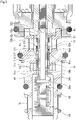
- a capacity control valve 100 shown in Patent Citation 1 includes, as illustrated in FIG. 10 , a valve housing 110 which is provided with a first communication path 112 communicating a first valve chamber 120 provided with a first valve seat 110a with a discharge chamber of a variable displacement compressor, a second communication path 113 communicating a second valve chamber 130 provided with a second valve seat 182a with a suction chamber of the variable displacement compressor, and a third communication path 114 communicating a third valve chamber 140 formed on the side opposite to the second valve chamber 130 in the axial direction with respect to the first valve chamber 120 with a control chamber of the variable displacement compressor, a main valve element 151 which integrally includes a first valve portion 151a coming into contact with and separating from the first valve seat 110a in the first valve chamber 120 so as to open and close the communication between the discharge chamber and the control chamber and a second valve portion 151b coming into contact with and separating from a second valve seat 182a in the second valve chamber 130 so as to open and close the communication between the control chamber and the suction chamber
- the solenoid 180 of the capacity control valve 100 is energized and the main valve element 151 moves in the axial direction when starting the variable displacement compressor, the first valve portion 151a closes the main valve and the second valve portion 151b opens the second valve so that a communication flow path extending from the third valve chamber 140 to the second valve chamber 130 is formed inside the valve housing 110 by the auxiliary communication path 190 and the intermediate communication path 155. Further, since the suction pressure Ps of the suction chamber decreases as the variable displacement compressor is started, the high-pressure fluid in the control chamber moves due to a pressure difference with the suction chamber and passes through a flow path formed inside the valve housing 110 so as to be discharged in a short time.
- Patent Citation 2 discloses control valve comprising a valve main body having a first valve chamber, a second valve chamber and a third valve chamber, said first valve chamber communicating with a first communication passage, said second valve chamber having a second valve seat face for a valve hole and communicating with a second communication passage, said third valve chamber having a third valve seat face and communicating with a third communication passage; a valve body having a first valve member, a second valve member and a third valve member, said second valve member having an intermediate communication passage therein communicating with said first valve chamber and said third communication passage, said second valve member opening and closing a valve hole with respect to second valve seat face, thereby communicating with said first valve chamber and said second valve chamber, said third valve member performing a valve opening/closing action with respect to said third valve seat face in an reverse manner against said second valve member, thereby opening or closing the communication with said intermediate communication passage and said third communication passage, said first valve member performing a valve opening/closing action in the same direction to said second valve member; a pressure sensing member having a valve
- the present invention has been made in view of such problems and an object of the present invention is to provide a capacity control valve having good responsiveness during start-up and good control accuracy during normal control.
- a capacity control valve includes: a valve housing provided with a Pc port through which a control fluid of a control pressure passes, a Pd port through which a discharge fluid of a discharge pressure passes and a Ps port through which a suction fluid of a suction pressure passes; a main valve formed by a main valve seat and a main valve element having a main valve portion, the main valve being capable of closing and opening a communication between the Pc port and the Pd port when the main valve portion of the main valve element driven by a drive force of a solenoid comes into contact with and separates from the main valve seat; a pressure-sensitive valve which is opened by an ambient pressure; a hollow tube member which forms a part of the pressure-sensitive valve and allows the Pc port to communicate with the Ps port through a hollow communication path formed therein when the pressure-sensitive valve is opened; and an auxiliary communication path which allows the Pc port to communicate with the Ps port independently of the pressure-sensitive valve.
- the auxiliary communication path is configured to be able to increase a flow path cross-sectional area thereof after the main valve is closed. According to the aforesaid feature, it is possible to promptly discharge a fluid by increasing the flow path cross-sectional area of the auxiliary communication path during the start-up of the variable displacement compressor and to increase controllability by decreasing the flow path cross-sectional area of the auxiliary communication path during normal control.
- the auxiliary communication path is a communication hole which is formed in the hollow tube member and communicates with the hollow communication path
- the main valve element is externally fitted to the hollow tube member with a spring so as to be axially movable, and the main valve element relatively moves with respect to the hollow tube member so as to be capable of closing at least a part of an opening of the communication hole.
- the flow path cross-sectional area of the auxiliary communication path upon a close state of the main valve is a half or less of the flow path cross-sectional area of the auxiliary communication path upon a full open state of the main valve. According to this preferable configuration, since the flow rate of the Pc port and the Ps port decreases during normal control, controllability is good.
- the auxiliary communication path is a communication hole which is formed in the hollow tube member and communicates with the hollow communication path.
- the auxiliary communication path can be formed with a simple structure.
- the main valve element is externally fitted to the hollow tube member with a spring so as to be axially movable, and the main valve element relatively moves with respect to the hollow tube member so as to be capable of closing at least a part of an opening of the communication hole. Since it is possible to change the flow path cross-sectional area of the auxiliary communication path by the corporation between the main valve element and the communication hole, the structure of the main valve element is simple and the movement of the main valve element is smooth.
- the main valve element is internally fitted to the valve housing. According to this preferable configuration, the movement of the main valve element is smoother.
- the main valve element and the hollow tube member are provided with engagement portions capable of engaging with each other in accordance with a relative movement between the main valve element and the hollow tube member. According to this preferable configuration, since the movement position of the main valve element with respect to the hollow tube member in the closing and opening direction of the communication hole is regulated by the engagement portions, the structure is simple.
- a capacity control valve according to a first embodiment will be described with reference to FIGS. 1 to 8 .
- the left and right sides as viewed from the front side in FIG. 2 will be described as the left and right sides of the capacity control valve.
- a capacity control valve V of the present invention is incorporated in a variable displacement compressor M used in an air conditioning system of an automobile or the like and variably controls a pressure of a working fluid (hereinafter, simply referred to as a "fluid") which is a refrigerant so that a discharge amount of the variable displacement compressor M is controlled to adjust the air conditioning system to a desired cooling capacity.
- a working fluid hereinafter, simply referred to as a "fluid"
- variable displacement compressor M includes a casing 1 having a discharge chamber 2, a suction chamber 3, a control chamber 4, and a plurality of cylinders 4a.
- the variable displacement compressor M is provided with a communication path (not illustrated) allowing the control chamber 4 and the suction chamber 3 to directly communicate with each other and this communication path is provided with a fixed orifice for adjusting a pressure between the suction chamber 3 and the control chamber 4 in a balanced state.
- variable displacement compressor M includes a rotating shaft 5 which is rotationally driven by an engine (not illustrated) installed outside the casing 1, a swash plate 6 which is eccentrically connected to the rotating shaft 5 inside the control chamber 4 by a hinge mechanism 8, and a plurality of pistons 7 which are connected to the swash plate 6 and are fitted so as to be movable in a reciprocating manner inside the respective cylinders 4a and continuously changes an inclination angle of the swash plate 6 by appropriately controlling a pressure inside the control chamber 4 while using a suction pressure Ps of the suction chamber 3 sucking a fluid by using the capacity control valve V driven to be opened and closed by an electromagnetic force, a discharge pressure Pd of the discharge chamber 2 discharging a fluid pressurized by the piston 7, and a control pressure Pc of the control chamber 4 accommodating the swash plate 6 so that a stroke amount of the piston 7 is changed to control a discharge amount of the fluid.
- the capacity control valve V incorporated in the variable displacement compressor M is omitted
- the inclination angle of the swash plate 6 with respect to the rotating shaft 5 becomes smaller so that the stroke amount of the piston 7 decreases as the control pressure Pc inside the control chamber 4 becomes higher.
- the swash plate 6 is substantially perpendicular to the rotating shaft 5, that is, slightly inclined from the vertical direction.
- the stroke amount of the piston 7 is minimized and the pressurization of the fluid inside the cylinder 4a by the piston 7 is minimized, the discharge amount of the fluid to the discharge chamber 2 decreases and the cooling capacity of the air conditioning system is minimized.
- the inclination angle of the swash plate 6 with respect to the rotating shaft 5 becomes larger so that the stroke amount of the piston 7 increases as the control pressure Pc inside the control chamber 4 becomes lower.
- the pressure becomes a certain level or less
- the inclination angle of the swash plate 6 with respect to the rotating shaft 5 is maximized.
- the stroke amount of the piston 7 is maximized and the pressurization of the fluid inside the cylinder 4a by the piston 7 is maximized, the discharge amount of the fluid to the discharge chamber 2 increases and the cooling capacity of the air conditioning system is maximized.
- the capacity control valve V incorporated in the variable displacement compressor M adjusts a current flowing through a coil 86 constituting a solenoid 80 so as to control the opening and closing of a first valve 50 and a second valve 53 which are main valves of the capacity control valve V and to control the opening and closing of a pressure-sensitive valve 55 by an ambient fluid pressure so that the fluid flowing into the control chamber 4 or flowing out from the control chamber 4 is controlled to variably control the control pressure Pc inside the control chamber 4.
- the first valve 50 includes a main valve element 51 and a first valve seat 10a which is a main valve seat formed on an inner peripheral surface of a valve housing 10 and a first valve portion 51a which is a main valve portion formed in a left axial end of the main valve element 51 comes into contact with and separates from the first valve seat 10a.
- the second valve 53 includes a second valve element 52 which is a hollow tube member and a second valve seat 82a which is formed in a left axial end surface corresponding to an opening end surface of the fixed iron core 82 and a second valve portion 52a which is formed in a right axial end surface of an annular flange portion 52c extending outward in the radial direction from the outer peripheral surface of the substantially axial center of the second valve element 52 comes into contact with and separates from the second valve seat 82a.
- a second valve element 52 which is a hollow tube member and a second valve seat 82a which is formed in a left axial end surface corresponding to an opening end surface of the fixed iron core 82 and a second valve portion 52a which is formed in a right axial end surface of an annular flange portion 52c extending outward in the radial direction from the outer peripheral surface of the substantially axial center of the second valve element 52 comes into contact with and separates from the second valve seat 82a.
- the pressure-sensitive valve 55 includes an adapter 70 of a pressure-sensitive element 60 and a pressure-sensitive valve seat 54a which is formed in a left axial end portion of a pressure-sensitive valve member 54 corresponding to a hollow tube member and a right axial end 70a of the adapter 70 comes into contact with and separates from the pressure-sensitive valve seat 54a.
- the capacity control valve V mainly includes the valve housing 10 which is formed of a metal material or a resin material, the main valve element 51, the second valve element 52, and the pressure-sensitive valve member 54 which are disposed (i.e., internally fitted) so as to be movable in a reciprocating manner in the axial direction inside the valve housing 10, the pressure-sensitive element 60 which applies a biasing force to the main valve element 51, the second valve element 52, and the pressure-sensitive valve member 54 rightward in the axial direction in response to an ambient fluid pressure, and the solenoid 80 which is connected to the valve housing 10 and applies a drive force to the main valve element 51, the second valve element 52, and the pressure-sensitive valve member 54.
- the solenoid 80 mainly includes a casing 81 which has an opening portion 81a opening leftward in the axial direction, a substantially cylindrical fixed iron core 82 which is inserted into the opening portion 81a of the casing 81 from the left side in the axial direction and is fixed to the inner radial side of the casing 81, a drive rod 83 which is fixed to the inner radial side of the fixed iron core 82 so as to be movable in a reciprocating manner in the axial direction and of which a left axial end portion is connected and fixed to the second valve element 52, a movable iron core 84 which is fixed to a right axial end portion of the drive rod 83, a coil spring 85 which is provided between the fixed iron core 82 and the movable iron core 84 and urges the movable iron core 84 rightward in the axial direction, and an excitation coil 86 which is wound on the outside of the fixed iron core 82 through a bobbin.
- the casing 81 is provided with a concave portion 81b which is recessed rightward in the axial direction from the radial center of the left axial end and the right axial end portion of the valve housing 10 is inserted and fixed to the concave portion 81b.
- the fixed iron core 82 includes a cylindrical portion 82b which is formed of a rigid element corresponding to a magnetic material such as iron or silicon steel and is provided with an insertion hole 82c extending in the axial direction and allowing the drive rod 83 to be inserted therethrough and an annular flange portion 82d which extends outward in the radial direction from the outer peripheral surface of the left axial end portion of the cylindrical portion 82b and a concave portion 82e is formed so as to be recessed rightward in the axial direction from the radial center of the left axial end of the cylindrical portion 82b.
- the valve housing 10 has a substantially cylindrical shape with a bottom by press-inserting a partition adjustment member 11 into the left axial end portion.
- the main valve element 51, the second valve element 52, and the pressure-sensitive valve member 54 are disposed inside the valve housing 10 so as to be movable in a reciprocating manner in the axial direction and a guide surface 10b having a small diameter and slidable in the outer peripheral surface of the main valve element 51 is formed in a part of the inner peripheral surface of the valve housing 10.
- the partition adjustment member 11 can adjust the urging force of the pressure-sensitive element 60 by adjusting the installation position of the valve housing 10 in the axial direction.
- a first valve chamber 20 in which a left axial side corresponding to the side of the first valve portion 51a of the main valve element 51 is disposed, a second valve chamber 30 which is formed on the right axial side corresponding to a back pressure side of the main valve element 51, and a pressure-sensitive chamber 40 which is formed at a position on the side opposite to the second valve chamber 30 in the axial direction with respect to the first valve chamber 20 are formed inside the valve housing 10.
- the second valve chamber 30 is defined by the outer peripheral surface on the back pressure side of the main valve element 51, the outer peripheral surface of the second valve element 52, the concave portion 82e and the left axial end surface corresponding to the opening end surface of the fixed iron core 82, and the right axial inner peripheral surface in relation to the guide surface 10b of the valve housing 10.
- valve housing 10 is provided with a Pd port 12 which communicates the first valve chamber 20 with the discharge chamber 2 of the variable displacement compressor M, a Ps port 13 which communicates the second valve chamber 30 with the suction chamber 3 of the variable displacement compressor M, and a Pc port 14 which communicates the pressure-sensitive chamber 40 with the control chamber 4 of the variable displacement compressor M.
- the main valve element 51 is formed in a cylindrical shape, includes a cylindrical portion 51b, the first valve portion 51a which is formed on the outer radial side of the left axial end of the cylindrical portion 51b, a sliding portion 51c which protrudes in an annular shape inward in the radial direction from the inner peripheral surface of the left axial end portion of the cylindrical portion 51b and is formed such that the inner diameter is smaller than the cylindrical portion 51b, and a regulation portion 51d which protrudes in an annular shape inward in the radial direction from the inner peripheral surface of the right axial end portion of the cylindrical portion 51b and is formed such that the inner diameter is smaller than the sliding portion 51c, and is externally fitted to the pressure-sensitive valve member 54 so as to be movable in the axial direction.
- an annular gap is formed between the inner peripheral surface of the cylindrical portion 51b and an outer peripheral surface of a cylindrical portion 54b of the pressure-sensitive valve member 54 so as to separate them in the radial direction while the main valve element 51 is externally fitted to the pressure-sensitive valve member 54 and the main valve element 51 is easily relatively movable in the axial direction with respect to the pressure-sensitive valve member 54.
- the pressure-sensitive valve member 54 is formed in a substantially cylindrical shape and a substantially turret shape in the side view and includes the cylindrical portion 54b, a flange portion 54c which extends outward in the radial direction from the outer peripheral surface of the left axial end portion of the cylindrical portion 54b and has the pressure-sensitive valve seat 54a formed in the left axial end, and an attachment portion 54d which is formed in the right axial end portion of the cylindrical portion 54b and has a diameter smaller than the cylindrical portion 54b and the cylindrical portion 54b is formed such that the outer diameter is slightly smaller than the inner diameter of the sliding portion 51c of the main valve element 51.
- the attachment portion 54d is formed such that the outer diameter is slightly smaller than the inner diameter of the regulation portion 51d of the main valve element 51 and the axial dimension is longer than the regulation portion 51d of the main valve element 51.
- the attachment portion 54d of the pressure-sensitive valve member 54 is inserted and fitted to the inner radial side of the regulation portion 51d of the main valve element 51 so as to be movable in the axial direction while the main valve element 51 is externally fitted to the pressure-sensitive valve member 54 so that the right axial end portion of the attachment portion 54d protrudes from the right axial opening portion of the regulation portion 51d of the main valve element 51 and an end surface 54e corresponding to the right axial engagement portion of the cylindrical portion 54b of the pressure-sensitive valve member 54 can engage with a regulation end surface 51f corresponding to the left axial engagement portion of the regulation portion 51d of the main valve element 51.
- the second valve element 52 is formed in a substantially cylindrical shape with a flange and includes a cylindrical portion 52b, the annular flange portion 52c which extends outward in the radial direction from the outer peripheral surface of the substantially axial center portion of the cylindrical portion 52b, and an attachment concave portion 52d which is recessed rightward in the axial direction from the radial center of the left axial end of the cylindrical portion 52b and the right axial end portion of the attachment portion 54d of the pressure-sensitive valve member 54 is inserted and fixed to the attachment concave portion 52d so that the second valve element 52 and the pressure-sensitive valve member 54 are integrally connected to each other.
- the drive rod 83 is connected and fixed to the right axial end portion of the second valve element 52 and the main valve element 51, the second valve element 52, and the pressure-sensitive valve member 54 are movable together in the axial direction.
- a coil spring 57 which is a spring is externally fitted to the left axial cylindrical portion 52b in relation to the flange portion 52c of the second valve element 52, the left axial end of the coil spring 57 comes into contact with an outer radial side of a regulation end surface 51g which is the right axial engagement portion of the regulation portion 51d of the main valve element 51, and the right axial end of the coil spring 57 comes into contact with the left axial end surface of the flange portion 52c of the second valve element 52.
- the coil spring 57 applies a biasing force leftward in the axial direction so that the left axial regulation end surface 51f of the regulation portion 51d of the main valve element 51 engages with the right axial end surface 54e of the cylindrical portion 54b of the pressure-sensitive valve member 54.
- the spring constant of the coil spring 57 is set to be smaller than that of a coil spring 62 provided in the pressure-sensitive element 60.
- annular groove 58 is formed in the outer periphery of the attachment portion 54d of the pressure-sensitive valve member 54 to which the regulation portion 51d of the main valve element 51 is externally fitted.
- the groove 58 is formed by the outer peripheral surface of the attachment portion 54d of the pressure-sensitive valve member 54, the right axial end surface 54e of the cylindrical portion 54b of the pressure-sensitive valve member 54, and a left axial end surface 52e of the cylindrical portion 52b of the second valve element 52 and the axial position of the main valve element 51, that is, the regulation portion 51d relatively moving in the axial direction with respect to the second valve element 52 and the pressure-sensitive valve member 54 is determined by the groove 58.
- the right axial end of the main valve element 51 that is, the right axial regulation end surface 51g of the regulation portion 51d of the main valve element 51 is separated from the left axial end of the second valve element 52, that is, the end surface 52e corresponding to the left axial engagement portion of the cylindrical portion 52b of the second valve element 52 by an axial dimension A (see FIG. 7A ).
- the axial separation dimension A between the regulation end surface 51g of the main valve element 51 and the end surface 52e of the second valve element 52 is set to a dimension of a substantially half of the right axial side of the opening of the communication hole 90 corresponding to the auxiliary communication path to be described later. That is, the pressure-sensitive valve member 54 is further movable in the axial direction by the separation dimension A after the first valve 50 is closed.
- a hollow communication path 56 which penetrates in the axial direction by connecting a hollow hole is formed inside the second valve element 52 and the pressure-sensitive valve member 54.
- the hollow communication path 56 communicates with the inside of the concave portion 82e of the fixed iron core 82 through a plurality of through-holes 52f penetrating the right axial cylindrical portion 52b in relation to the flange portion 52c of the second valve element 52 in the radial direction.
- the hollow communication path 56 communicates with the first valve chamber 20 and/or the pressure-sensitive chamber 40 through a plurality of communication holes 90 penetrating the left axial end portion of the cylindrical portion 54b of the pressure-sensitive valve member 54 in the radial direction.
- a substantially half of the right axial side of the opening preferably, a half or more of the opening of the communication hole 90 is closed by the sliding portion 51c of the main valve element 51 externally fitted to the pressure-sensitive valve member 54 (see FIG. 8A ).
- the pressure-sensitive element 60 mainly includes the bellows core 61 in which the coil spring 62 is embedded and the adapter 70 which is formed in the right axial end portion of the bellows core 61 and the left axial end of the bellows core 61 is fixed to the partition adjustment member 11.
- the pressure-sensitive element 60 is disposed inside the pressure-sensitive chamber 40 and the right axial end 70a of the adapter 70 sits on the pressure-sensitive valve seat 54a of the pressure-sensitive valve member 54 by the urging force of the coil spring 62 and the bellows core 61.
- the pressure-sensitive element 60 contracts due to an ambient fluid pressure when the suction pressure Ps inside the hollow communication path 56 is high so as to separate the right axial end 70a of the adapter 70 from the pressure-sensitive valve seat 54a of the pressure-sensitive valve member 54 and open the pressure-sensitive valve 55 (see FIGS. 4 and 5 ). Accordingly, for example, when the suction pressure Ps inside the second valve chamber 30 is high, the control pressure Pc can be promptly released to the second valve chamber 30 through the hollow communication path 56 and the through-hole 52f of the second valve element 52.
- the first valve portion 51a of the main valve element 51 is separated from the first valve seat 10a formed on the inner peripheral surface of the valve housing 10 so as to open the first valve 50.
- the left axial regulation end surface 51f of the regulation portion 51d of the main valve element 51 engages with the right axial end surface 54e of the cylindrical portion 54b of the pressure-sensitive valve member 54 by the urging force of the coil spring 57 (see FIG. 7A ) and a substantially half of the right axial side of the opening of the communication hole 90 is closed by the sliding portion 51c of the main valve element 51 externally fitted to the pressure-sensitive valve member 54 (see FIG. 8A ).
- the control pressure Pc is higher than the control pressure Pc before the non-energized state, is higher than the suction pressure Ps, and is expressed by a relational expression of Pd ⁇ Pc > Ps. For that reason, a fluid inside the control chamber 4 flows into the suction chamber 3 through the communication path and the fixed orifice directly communicating the control chamber 4 with the suction chamber 3. The inflow of the fluid is performed until the discharge pressure Pd, the suction pressure Ps, and the control pressure Pc are equalized.
- the main valve element 51, the second valve element 52, and the pressure-sensitive valve member 54 move leftward in the axial direction so that the first valve portion 51a of the main valve element 51 sits on the first valve seat 10a formed on the inner peripheral surface of the valve housing 10 so as to close the first valve 50 (see FIG. 4 ).
- the second valve portion 52a of the second valve element 52 is separated from the second valve seat 82a formed on the opening end surface of the fixed iron core 82 so that the second valve 53 is opened.
- the main valve element 51 moves together leftward in the axial direction without relatively moving in the axial direction with respect to the second valve element 52 and the pressure-sensitive valve member 54 by the urging force of the coil spring 57 until the non-energized state is changed to the energized state so that the first valve 50 is closed (see FIGS. 7B and 8B ).
- the current for energizing the coil 86 of the solenoid 80 is controlled to increase from the closed state of the first valve 50 and the movable iron core 84 and the drive rod 83 are further moved leftward in the axial direction so that the second valve element 52 and the pressure-sensitive valve member 54 move leftward in the axial direction against the urging force of the coil spring 57 (see FIG. 5 ).
- the present invention is not limited to a drive force generated by the solenoid 80 and even when a force generated by the suction pressure Ps for moving the second valve element 52 and the pressure-sensitive valve member 54 rightward in the axial direction exceeds the urging force of the coil spring 57, the second valve element 52 and the pressure-sensitive valve member 54 move leftward in the axial direction.
- the main valve element 51 relatively moves rightward in the axial direction by the dimension A with respect to the second valve element 52 and the pressure-sensitive valve member 54 inside the groove 58 formed in the outer periphery of the attachment portion 54d of the pressure-sensitive valve member 54 to an axial position in which the right axial end surface 54e of the cylindrical portion 54b of the pressure-sensitive valve member 54 is separated from the left axial regulation end surface 51f of the regulation portion 51d of the main valve element 51 in the axial direction so as to release the engagement and the right axial regulation end surface 51g of the regulation portion 51d of the main valve element 51 engages with the left axial end surface 52e of the cylindrical portion 52b of the second valve element 52 (see FIG. 7C ).
- the left axial end of the sliding portion 51c of the main valve element 51 moves relatively rightward in the axial direction by the dimension A, that is, the substantially half of the right axial side of the opening of the communication hole 90 to a position not overlapping the communication hole 90 formed in the cylindrical portion 54b of the pressure-sensitive valve member 54 so that the entire opening of the communication hole 90 of the pressure-sensitive valve member 54 is opened (see FIG. 8C ) .
- a pressure difference between the control pressure Pc of the control chamber 4 and the suction pressure Ps of the suction chamber 3 generates a flow of a fluid flowing from the Pc port 14 to the hollow communication path 56 through the communication hole 90 and flowing to the Ps port 13 (indicated by a solid arrow in FIGS. 5 and 6 ) and a flow of a fluid flowing from the inside of the pressure-sensitive chamber 40 to the hollow communication path 56 through the pressure-sensitive valve 55 and flowing to the Ps port 13 (indicated by a solid line in FIGS. 4 and 5 ).
- the capacity control valve V of the present embodiment opens the pressure-sensitive valve 55 communicating with the hollow communication path 56 and relatively moves the main valve element 51 in the axial direction with respect to the second valve element 52 and the pressure-sensitive valve member 54 so as to increase the flow path cross-sectional area of the communication hole 90 communicating with the hollow communication path 56.
- the pressure-sensitive element 60 expands when a liquefied refrigerant is discharged and the suction pressure Ps decreases, the right axial end 70a of the adapter 70 sits on the pressure-sensitive valve seat 54a of the pressure-sensitive valve member 54. Accordingly, since the wide flow path cross-sectional area of the communication hole 90 can be maintained even when the suction pressure Ps is low and the pressure-sensitive valve 55 is not opened, it is possible to reliably discharge a liquefied fluid (see FIG. 6 ).
- the capacity control valve V closes the first valve 50 and relatively moves the main valve element 51 in the axial direction with respect to the second valve element 52 and the pressure-sensitive valve member 54 so as to maintain the wide flow path cross-sectional area of the communication hole 90.
- the control pressure Pc and the suction pressure Ps are easily maintained at the equal pressure (i.e., the same pressure). For that reason, it is possible to improve the operation efficiency by stabilizing the stroke of the piston 7 inside the cylinder 4a of the control chamber 4 and maintaining the maximum capacity state.
- the current for energizing the coil 86 of the solenoid 80 is controlled to decrease and the main valve element 51 is relatively moved in the axial direction with respect to the second valve element 52 and the pressure-sensitive valve member 54 while the first valve 50 is maintained in a closed state so that the flow path cross-sectional area of the communication hole 90 is narrowed (see FIG. 8B ). Accordingly, the flow rate from the Pc port 14 to the Ps port 13 decreases so that the control pressure Pc can be higher than the suction pressure Ps (Pc > Ps). For this reason, since the control pressure Pc of the control chamber 4 can be increased, the output of the variable displacement compressor M can be decreased to a desired output and controllability is high.
- the auxiliary communication path communicating the Pc port 14 with the Ps port 13 is formed by the communication hole 90 of the pressure-sensitive valve member 54 communicating with the hollow communication path 56 separately from the pressure-sensitive valve 55, the auxiliary communication path can be formed in the capacity control valve V with a simple structure. Further, since the communication hole 90 is provided in the small-diameter cylindrical portion 54b of the pressure-sensitive valve member 54, the externally fitted main valve element 51 can be decreased in size.
- the main valve element 51 is externally fitted to the second valve element 52 and the pressure-sensitive valve member 54 through the coil spring 57 so as to be movable in the axial direction and moves relatively in the axial direction with respect to the second valve element 52 and the pressure-sensitive valve member 54 so as to close at least a part of the opening of the communication hole 90, it is possible to change the flow path cross-sectional area of the communication hole 90 by the cooperation between the main valve element 51 and the communication hole 90 and to have a simple structure. Furthermore, since the main valve element 51 is externally fitted to the cylindrical portion 54b of the pressure-sensitive valve member 54 and is internally fitted to the guide surface 10b of the valve housing 10, the movement of the main valve element 51 in the axial direction can be smoothly performed.
- the structure is simple.
- a capacity control valve V of the second embodiment will be described.
- a communication hole 290 which is an auxiliary communication path is formed so as to correspond to an axial position of an annular groove portion 291 provided on an outer periphery of a cylindrical portion 254b of a pressure-sensitive valve member 254 to which a sliding portion 251c of a main valve element 251 is externally fitted
- a structure that opens and closes the communication hole 290 by the main valve element 251 is a so-called spool valve structure.
- the communication hole 90 formed in the cylindrical portion 54b of the pressure-sensitive valve member 54 has been described such that a substantially half of the right axial side of the opening of the communication hole 90 is closed by the sliding portion 51c of the main valve element 51 externally fitted to the pressure-sensitive valve member 54, but the present invention is not limited thereto.
- the opening of the communication hole 90 may be fully closed by the sliding portion 51c of the main valve element 51.
- the regulation portion 51d of the main valve element 51 is externally fitted into the groove 58 so that the engagement portions engage with each other and the axial position of the main valve element 51 relatively moving in the axial direction with respect to the second valve element 52 and the pressure-sensitive valve member 54 is determined, but the present invention is not limited thereto.
- the axial position of the main valve element in the non-energized state may be determined by the engagement between the engagement portion of the regulation portion extending outward in the radial direction from the outer peripheral surface of the cylindrical portion of the main valve element and the engagement portion provided in the inner peripheral surface of the valve housing 10.
- the second valve element 52 and the pressure-sensitive valve member 54 constituting the hollow tube member may be integrally formed with each other.
- the auxiliary communication path can increase the flow path cross-sectional area after the first valve portion 51a of the main valve element 51 sits on the first valve seat 10a formed on the inner peripheral surface of the valve housing 10 so that the first valve 50 is closed
- the auxiliary communication path may be a through-hole provided in the adapter 70 constituting the pressure-sensitive valve 55 or an axial hole provided in the valve housing 10.
- the communication path and the fixed orifice which directly communicate the control chamber 4 and the suction chamber 3 of the variable displacement compressor M with each other may not be provided.
- the second valve may not be provided and the second valve portion 52a of the second valve element 52 may function as a support member that receives an axial load and does not essentially need a sealing function.
- the second valve chamber 30 may be provided on the side opposite to the solenoid 80 in the axial direction and the pressure-sensitive chamber 40 may be provided on the side of the solenoid 80.
- the coil spring 57 is not limited to a compression spring, but may be a tension spring or have a shape other than a coil shape.
- the pressure-sensitive element 60 may not use a coil spring therein.
Claims (4)
- Soupape de réglage de capacité (V) pour régler une capacité d'un fluide, comprenant :un corps de soupape (10) pourvu d'un raccord Pc (14), d'un raccord Pd (12) et d'un raccord Ps (13),une soupape principale formée par un siège de soupape principale (10a) et un élément de soupape principale (51, 251) ayant une partie de soupape principale (51a), la soupape principale étant en mesure de fermer et d'ouvrir une communication entre le port Pc (14) et le port Pd (12) lorsque la partie de soupape principale (51a) de l'élément de soupape principale (51, 251), entraînée par une force d'entraînement d'un solénoïde, vient en contact avec le, et est éloignée du, siège de soupape principale (10a),une soupape (55) sensible à la pression qui est ouverte par une pression ambiante,un élément de tube creux (54, 254) qui forme une partie de la soupape (55) sensible à la pression et rend possible au raccord Pc (14) de communiquer avec le port Ps (13) par un chemin creux de communication (56) formé là-dedans, lorsque la soupape (55) sensible à la pression est ouverte, etun chemin de communication auxiliaire (90, 290) qui rend possible au port Pc (14) de communiquer avec le port Ps (13) indépendamment de la soupape (55) sensible à la pression,le chemin de communication auxiliaire (90, 290) étant un trou de communication qui est formé dans l'élément de tube creux (52) et communique avec le chemin creux de communication (56),caractérisée en ce que le chemin de communication auxiliaire (90, 290) est configuré pour être en mesure d'augmenter une section transversale de chemin de flux de celui-ci une fois la soupape principale est fermée,l'élément de soupape principale (51, 251) étant montée extérieurement sur l'élément de tube creux (52) au moyen d'un ressort (57) afin d'être axialement mobile, etl'élément de soupape principale (51, 251) se déplaçant relativement par rapport à l'élément de tube creux (52) afin d'être en mesure de fermer au moins une partie d'une ouverture du trou de communication (90, 290).
- Soupape de réglage de capacité (V) selon la revendication 1, caractérisée en ce que, dans un état fermé de la soupape principale, la section transversale du chemin auxiliaire de communication (90, 290) est la moitié ou moins de la section transversale du chemin auxiliaire de communication (90, 290) dans un état entièrement ouvert de la soupape principale.
- Soupape de réglage de capacité (V) selon la revendication 1 ou 2, caractérisée en ce que l'élément de soupape principale (51, 251) est monté à l'intérieur du corps de soupape (10).
- Soupape de réglage de capacité (V) selon l'une des revendications 1 à 3, caractérisée en ce que l'élément de soupape principale (51, 251) et l'élément de tube creux (52) sont pourvus de parties d'introduction (51f, 51g) adaptées pour être introduite l'une dans l'autre selon un mouvement relatif entre l'élément de soupape principale (51, 251) et l'élément de tube creux (52).
Applications Claiming Priority (2)
| Application Number | Priority Date | Filing Date | Title |
|---|---|---|---|
| JP2018033902 | 2018-02-27 | ||
| PCT/JP2019/007187 WO2019167912A1 (fr) | 2018-02-27 | 2019-02-26 | Soupape de réglage de capacité |
Publications (3)
| Publication Number | Publication Date |
|---|---|
| EP3760864A1 EP3760864A1 (fr) | 2021-01-06 |
| EP3760864A4 EP3760864A4 (fr) | 2021-11-03 |
| EP3760864B1 true EP3760864B1 (fr) | 2022-11-16 |
Family
ID=67805767
Family Applications (1)
| Application Number | Title | Priority Date | Filing Date |
|---|---|---|---|
| EP19760096.8A Active EP3760864B1 (fr) | 2018-02-27 | 2019-02-26 | Soupape de réglage de capacité |
Country Status (6)
| Country | Link |
|---|---|
| US (1) | US11873804B2 (fr) |
| EP (1) | EP3760864B1 (fr) |
| JP (1) | JP7139084B2 (fr) |
| KR (1) | KR102352195B1 (fr) |
| CN (1) | CN111742141B (fr) |
| WO (1) | WO2019167912A1 (fr) |
Families Citing this family (17)
| Publication number | Priority date | Publication date | Assignee | Title |
|---|---|---|---|---|
| US11225962B2 (en) | 2018-05-23 | 2022-01-18 | Eagle Industry Co., Ltd. | Capacity control valve |
| WO2020013155A1 (fr) | 2018-07-12 | 2020-01-16 | イーグル工業株式会社 | Soupape de commande de capacité |
| WO2020013154A1 (fr) | 2018-07-12 | 2020-01-16 | イーグル工業株式会社 | Vanne de régulation de capacité |
| CN112424473B (zh) | 2018-07-13 | 2023-02-28 | 伊格尔工业股份有限公司 | 容量控制阀 |
| JP7289604B2 (ja) | 2018-08-08 | 2023-06-12 | イーグル工業株式会社 | 容量制御弁 |
| EP3835578B1 (fr) | 2018-08-08 | 2023-12-06 | Eagle Industry Co., Ltd. | Soupape de régulation de capacité |
| WO2020095918A1 (fr) | 2018-11-07 | 2020-05-14 | イーグル工業株式会社 | Soupape de régulation de capacité |
| US11473684B2 (en) | 2018-12-04 | 2022-10-18 | Eagle Industry Co., Ltd. | Capacity control valve |
| KR102603184B1 (ko) * | 2018-12-04 | 2023-11-16 | 이구루코교 가부시기가이샤 | 용량 제어 밸브 |
| US11053933B2 (en) * | 2018-12-13 | 2021-07-06 | Eagle Industry Co., Ltd. | Displacement control valve |
| JP7391486B2 (ja) | 2019-03-01 | 2023-12-05 | イーグル工業株式会社 | 容量制御弁 |
| KR20210136128A (ko) | 2019-04-03 | 2021-11-16 | 이구루코교 가부시기가이샤 | 용량 제어 밸브 |
| CN113661324B (zh) | 2019-04-03 | 2023-06-06 | 伊格尔工业股份有限公司 | 容量控制阀 |
| EP3998401A4 (fr) | 2019-07-12 | 2023-07-12 | Eagle Industry Co., Ltd. | Soupape de régulation de capacité |
| WO2021215345A1 (fr) * | 2020-04-23 | 2021-10-28 | イーグル工業株式会社 | Vanne de régulation de capacité |
| US20230193889A1 (en) * | 2020-05-25 | 2023-06-22 | Eagle Industry Co., Ltd. | Capacity control valve |
| EP4160016A1 (fr) * | 2020-05-25 | 2023-04-05 | Eagle Industry Co., Ltd. | Soupape régulatrice de capacité |
Family Cites Families (46)
| Publication number | Priority date | Publication date | Assignee | Title |
|---|---|---|---|---|
| US3297048A (en) | 1963-10-10 | 1967-01-10 | Imhof Augustin | Safety valve |
| AU615200B2 (en) | 1987-06-30 | 1991-09-26 | Sanden Corporation | Refrigerant circuit with passageway control mechanism |
| CH681384A5 (fr) | 1989-07-13 | 1993-03-15 | Balzers Hochvakuum | |
| JP3089816B2 (ja) | 1992-04-28 | 2000-09-18 | 株式会社豊田自動織機製作所 | 斜板式可変容量圧縮機 |
| JPH06200875A (ja) | 1993-01-08 | 1994-07-19 | Toyota Autom Loom Works Ltd | 揺動斜板式可変容量圧縮機 |
| JP3175536B2 (ja) * | 1995-06-13 | 2001-06-11 | 株式会社豊田自動織機製作所 | クラッチレス可変容量型圧縮機における容量制御構造 |
| JP3490557B2 (ja) * | 1995-10-31 | 2004-01-26 | 株式会社テージーケー | 容量可変圧縮機の容量制御装置 |
| US6010312A (en) | 1996-07-31 | 2000-01-04 | Kabushiki Kaisha Toyoda Jidoshokki Seiksakusho | Control valve unit with independently operable valve mechanisms for variable displacement compressor |
| JP2000064957A (ja) | 1998-08-17 | 2000-03-03 | Toyota Autom Loom Works Ltd | 容量可変型斜板式圧縮機および抜き側制御弁 |
| JP3583951B2 (ja) | 1999-06-07 | 2004-11-04 | 株式会社豊田自動織機 | 容量制御弁 |
| JP2001073939A (ja) | 1999-08-31 | 2001-03-21 | Toyota Autom Loom Works Ltd | 容量可変型圧縮機の制御弁及び容量可変型圧縮機 |
| JP2001099060A (ja) | 1999-10-04 | 2001-04-10 | Fuji Koki Corp | 可変容量型圧縮機用制御弁 |
| JP2001132632A (ja) * | 1999-11-10 | 2001-05-18 | Toyota Autom Loom Works Ltd | 容量可変型圧縮機の制御弁 |
| JP3941303B2 (ja) | 1999-11-17 | 2007-07-04 | 株式会社豊田自動織機 | 空調装置 |
| JP3780784B2 (ja) | 1999-11-25 | 2006-05-31 | 株式会社豊田自動織機 | 空調装置および容量可変型圧縮機の制御弁 |
| JP4242624B2 (ja) | 2002-09-26 | 2009-03-25 | イーグル工業株式会社 | 容量制御弁及びその制御方法 |
| JP2005069072A (ja) | 2003-08-22 | 2005-03-17 | Eagle Ind Co Ltd | 容量制御弁 |
| JP2005291142A (ja) | 2004-04-02 | 2005-10-20 | Zexel Valeo Climate Control Corp | 可変容量型圧縮機の制御装置及び圧力制御弁 |
| JP4431462B2 (ja) | 2004-08-10 | 2010-03-17 | 株式会社鷺宮製作所 | 斜板式容量可変型圧縮機および電磁制御弁 |
| JP4700048B2 (ja) | 2005-02-24 | 2011-06-15 | イーグル工業株式会社 | 容量制御弁 |
| JP2006307828A (ja) | 2005-03-31 | 2006-11-09 | Tgk Co Ltd | 可変容量圧縮機用制御弁 |
| WO2006137270A1 (fr) | 2005-06-22 | 2006-12-28 | Eagle Industry Co., Ltd. | Valve de contrôle de capacité |
| WO2007119380A1 (fr) | 2006-03-15 | 2007-10-25 | Eagle Industry Co., Ltd. | Soupape de regulation de capacite |
| KR101319565B1 (ko) | 2010-03-16 | 2013-10-23 | 이구루코교 가부시기가이샤 | 용량 제어밸브 |
| JP5878703B2 (ja) | 2010-09-06 | 2016-03-08 | 株式会社不二工機 | 可変容量型圧縮機用制御弁 |
| EP2653723B1 (fr) | 2010-12-09 | 2019-01-02 | Eagle Industry Co., Ltd. | Soupape de commande de capacité |
| JP5665722B2 (ja) | 2011-11-17 | 2015-02-04 | 株式会社豊田自動織機 | 容量制御弁 |
| JP6064132B2 (ja) | 2012-10-09 | 2017-01-25 | 株式会社テージーケー | 複合弁 |
| JP6216950B2 (ja) * | 2012-12-11 | 2017-10-25 | 株式会社テージーケー | 可変容量圧縮機用制御弁および制御弁 |
| WO2014091975A1 (fr) | 2012-12-12 | 2014-06-19 | イーグル工業株式会社 | Soupape de commande de capacité |
| EP3404262B1 (fr) * | 2013-01-31 | 2019-09-11 | Eagle Industry Co., Ltd. | Valve de commande de capacité |
| JP6103586B2 (ja) * | 2013-03-27 | 2017-03-29 | 株式会社テージーケー | 可変容量圧縮機用制御弁 |
| JP6206274B2 (ja) | 2014-03-19 | 2017-10-04 | 株式会社豊田自動織機 | 容量制御弁 |
| WO2017057160A1 (fr) * | 2015-09-29 | 2017-04-06 | 株式会社ヴァレオジャパン | Valve de régulation de compresseur à cylindrée variable |
| JP6383720B2 (ja) * | 2015-12-16 | 2018-08-29 | 株式会社不二工機 | 可変容量型圧縮機用制御弁 |
| JP6663227B2 (ja) | 2016-01-19 | 2020-03-11 | サンデン・オートモーティブコンポーネント株式会社 | 可変容量圧縮機の容量制御弁 |
| KR20170093349A (ko) * | 2016-02-05 | 2017-08-16 | 주식회사 뉴로스 | 가변용량 압축기의 전자제어밸브 |
| DE112017000921B4 (de) | 2016-02-22 | 2022-01-05 | Kabushiki Kaisha Toyota Jidoshokki | Taumelscheibenverdichter mit veränderbarer Verdrängung |
| JP6810131B2 (ja) * | 2016-03-17 | 2021-01-06 | イーグル工業株式会社 | 容量制御弁 |
| JP6714274B2 (ja) * | 2016-06-13 | 2020-06-24 | 株式会社テージーケー | 可変容量圧縮機用制御弁 |
| JP6626789B2 (ja) * | 2016-06-28 | 2019-12-25 | 株式会社不二工機 | 可変容量型圧縮機用制御弁 |
| JP6647156B2 (ja) * | 2016-06-28 | 2020-02-14 | 株式会社不二工機 | 可変容量型圧縮機用制御弁 |
| JP2018040385A (ja) | 2016-09-05 | 2018-03-15 | 株式会社テージーケー | 電磁弁 |
| JP7167067B2 (ja) | 2018-01-26 | 2022-11-08 | イーグル工業株式会社 | 容量制御弁 |
| WO2019159998A1 (fr) | 2018-02-15 | 2019-08-22 | イーグル工業株式会社 | Soupape de réglage de capacité |
| CN111712638B (zh) | 2018-02-15 | 2022-05-03 | 伊格尔工业股份有限公司 | 容量控制阀 |
-
2019
- 2019-02-26 KR KR1020207024987A patent/KR102352195B1/ko active IP Right Grant
- 2019-02-26 WO PCT/JP2019/007187 patent/WO2019167912A1/fr unknown
- 2019-02-26 US US16/969,175 patent/US11873804B2/en active Active
- 2019-02-26 CN CN201980012733.8A patent/CN111742141B/zh active Active
- 2019-02-26 EP EP19760096.8A patent/EP3760864B1/fr active Active
- 2019-02-26 JP JP2020503506A patent/JP7139084B2/ja active Active
Also Published As
| Publication number | Publication date |
|---|---|
| US11873804B2 (en) | 2024-01-16 |
| KR20200112965A (ko) | 2020-10-05 |
| JPWO2019167912A1 (ja) | 2021-02-04 |
| KR102352195B1 (ko) | 2022-01-17 |
| CN111742141A (zh) | 2020-10-02 |
| WO2019167912A1 (fr) | 2019-09-06 |
| EP3760864A1 (fr) | 2021-01-06 |
| JP7139084B2 (ja) | 2022-09-20 |
| CN111742141B (zh) | 2022-05-10 |
| EP3760864A4 (fr) | 2021-11-03 |
| US20200400134A1 (en) | 2020-12-24 |
Similar Documents
| Publication | Publication Date | Title |
|---|---|---|
| EP3760864B1 (fr) | Soupape de réglage de capacité | |
| US11225962B2 (en) | Capacity control valve | |
| JP7387237B2 (ja) | 容量制御弁 | |
| EP3822485B1 (fr) | Soupape de réglage de capacité | |
| EP3754190B1 (fr) | Soupape de réglage de capacité | |
| EP3754191B1 (fr) | Soupape de réglage de capacité | |
| EP3822484A1 (fr) | Soupape de commande de capacité | |
| EP4148274B1 (fr) | Vanne de régulation de capacité | |
| WO2020032088A1 (fr) | Soupape de régulation de capacité | |
| JP7358022B2 (ja) | 容量制御弁 | |
| CN112955684B (zh) | 容量控制阀 | |
| WO2020032089A1 (fr) | Soupape de régulation de capacité | |
| WO2020116436A1 (fr) | Vanne à commande de déplacement |
Legal Events
| Date | Code | Title | Description |
|---|---|---|---|
| STAA | Information on the status of an ep patent application or granted ep patent |
Free format text: STATUS: THE INTERNATIONAL PUBLICATION HAS BEEN MADE |
|
| PUAI | Public reference made under article 153(3) epc to a published international application that has entered the european phase |
Free format text: ORIGINAL CODE: 0009012 |
|
| STAA | Information on the status of an ep patent application or granted ep patent |
Free format text: STATUS: REQUEST FOR EXAMINATION WAS MADE |
|
| 17P | Request for examination filed |
Effective date: 20200907 |
|
| AK | Designated contracting states |
Kind code of ref document: A1 Designated state(s): AL AT BE BG CH CY CZ DE DK EE ES FI FR GB GR HR HU IE IS IT LI LT LU LV MC MK MT NL NO PL PT RO RS SE SI SK SM TR |
|
| AX | Request for extension of the european patent |
Extension state: BA ME |
|
| DAV | Request for validation of the european patent (deleted) | ||
| DAX | Request for extension of the european patent (deleted) | ||
| A4 | Supplementary search report drawn up and despatched |
Effective date: 20211005 |
|
| RIC1 | Information provided on ipc code assigned before grant |
Ipc: F04B 27/18 20060101AFI20210929BHEP |
|
| GRAP | Despatch of communication of intention to grant a patent |
Free format text: ORIGINAL CODE: EPIDOSNIGR1 |
|
| STAA | Information on the status of an ep patent application or granted ep patent |
Free format text: STATUS: GRANT OF PATENT IS INTENDED |
|
| RIC1 | Information provided on ipc code assigned before grant |
Ipc: F04B 27/18 20060101AFI20220620BHEP |
|
| INTG | Intention to grant announced |
Effective date: 20220713 |
|
| GRAS | Grant fee paid |
Free format text: ORIGINAL CODE: EPIDOSNIGR3 |
|
| GRAA | (expected) grant |
Free format text: ORIGINAL CODE: 0009210 |
|
| STAA | Information on the status of an ep patent application or granted ep patent |
Free format text: STATUS: THE PATENT HAS BEEN GRANTED |
|
| AK | Designated contracting states |
Kind code of ref document: B1 Designated state(s): AL AT BE BG CH CY CZ DE DK EE ES FI FR GB GR HR HU IE IS IT LI LT LU LV MC MK MT NL NO PL PT RO RS SE SI SK SM TR |
|
| REG | Reference to a national code |
Ref country code: GB Ref legal event code: FG4D |
|
| REG | Reference to a national code |
Ref country code: CH Ref legal event code: EP |
|
| REG | Reference to a national code |
Ref country code: DE Ref legal event code: R096 Ref document number: 602019022016 Country of ref document: DE |
|
| REG | Reference to a national code |
Ref country code: IE Ref legal event code: FG4D |
|
| REG | Reference to a national code |
Ref country code: AT Ref legal event code: REF Ref document number: 1531914 Country of ref document: AT Kind code of ref document: T Effective date: 20221215 |
|
| REG | Reference to a national code |
Ref country code: LT Ref legal event code: MG9D |
|
| REG | Reference to a national code |
Ref country code: NL Ref legal event code: MP Effective date: 20221116 |
|
| REG | Reference to a national code |
Ref country code: AT Ref legal event code: MK05 Ref document number: 1531914 Country of ref document: AT Kind code of ref document: T Effective date: 20221116 |
|
| PG25 | Lapsed in a contracting state [announced via postgrant information from national office to epo] |
Ref country code: SE Free format text: LAPSE BECAUSE OF FAILURE TO SUBMIT A TRANSLATION OF THE DESCRIPTION OR TO PAY THE FEE WITHIN THE PRESCRIBED TIME-LIMIT Effective date: 20221116 Ref country code: PT Free format text: LAPSE BECAUSE OF FAILURE TO SUBMIT A TRANSLATION OF THE DESCRIPTION OR TO PAY THE FEE WITHIN THE PRESCRIBED TIME-LIMIT Effective date: 20230316 Ref country code: NO Free format text: LAPSE BECAUSE OF FAILURE TO SUBMIT A TRANSLATION OF THE DESCRIPTION OR TO PAY THE FEE WITHIN THE PRESCRIBED TIME-LIMIT Effective date: 20230216 Ref country code: LT Free format text: LAPSE BECAUSE OF FAILURE TO SUBMIT A TRANSLATION OF THE DESCRIPTION OR TO PAY THE FEE WITHIN THE PRESCRIBED TIME-LIMIT Effective date: 20221116 Ref country code: FI Free format text: LAPSE BECAUSE OF FAILURE TO SUBMIT A TRANSLATION OF THE DESCRIPTION OR TO PAY THE FEE WITHIN THE PRESCRIBED TIME-LIMIT Effective date: 20221116 Ref country code: ES Free format text: LAPSE BECAUSE OF FAILURE TO SUBMIT A TRANSLATION OF THE DESCRIPTION OR TO PAY THE FEE WITHIN THE PRESCRIBED TIME-LIMIT Effective date: 20221116 Ref country code: AT Free format text: LAPSE BECAUSE OF FAILURE TO SUBMIT A TRANSLATION OF THE DESCRIPTION OR TO PAY THE FEE WITHIN THE PRESCRIBED TIME-LIMIT Effective date: 20221116 |
|
| PG25 | Lapsed in a contracting state [announced via postgrant information from national office to epo] |
Ref country code: RS Free format text: LAPSE BECAUSE OF FAILURE TO SUBMIT A TRANSLATION OF THE DESCRIPTION OR TO PAY THE FEE WITHIN THE PRESCRIBED TIME-LIMIT Effective date: 20221116 Ref country code: PL Free format text: LAPSE BECAUSE OF FAILURE TO SUBMIT A TRANSLATION OF THE DESCRIPTION OR TO PAY THE FEE WITHIN THE PRESCRIBED TIME-LIMIT Effective date: 20221116 Ref country code: LV Free format text: LAPSE BECAUSE OF FAILURE TO SUBMIT A TRANSLATION OF THE DESCRIPTION OR TO PAY THE FEE WITHIN THE PRESCRIBED TIME-LIMIT Effective date: 20221116 Ref country code: IS Free format text: LAPSE BECAUSE OF FAILURE TO SUBMIT A TRANSLATION OF THE DESCRIPTION OR TO PAY THE FEE WITHIN THE PRESCRIBED TIME-LIMIT Effective date: 20230316 Ref country code: HR Free format text: LAPSE BECAUSE OF FAILURE TO SUBMIT A TRANSLATION OF THE DESCRIPTION OR TO PAY THE FEE WITHIN THE PRESCRIBED TIME-LIMIT Effective date: 20221116 Ref country code: GR Free format text: LAPSE BECAUSE OF FAILURE TO SUBMIT A TRANSLATION OF THE DESCRIPTION OR TO PAY THE FEE WITHIN THE PRESCRIBED TIME-LIMIT Effective date: 20230217 |
|
| PG25 | Lapsed in a contracting state [announced via postgrant information from national office to epo] |
Ref country code: NL Free format text: LAPSE BECAUSE OF FAILURE TO SUBMIT A TRANSLATION OF THE DESCRIPTION OR TO PAY THE FEE WITHIN THE PRESCRIBED TIME-LIMIT Effective date: 20221116 |
|
| PG25 | Lapsed in a contracting state [announced via postgrant information from national office to epo] |
Ref country code: SM Free format text: LAPSE BECAUSE OF FAILURE TO SUBMIT A TRANSLATION OF THE DESCRIPTION OR TO PAY THE FEE WITHIN THE PRESCRIBED TIME-LIMIT Effective date: 20221116 Ref country code: RO Free format text: LAPSE BECAUSE OF FAILURE TO SUBMIT A TRANSLATION OF THE DESCRIPTION OR TO PAY THE FEE WITHIN THE PRESCRIBED TIME-LIMIT Effective date: 20221116 Ref country code: EE Free format text: LAPSE BECAUSE OF FAILURE TO SUBMIT A TRANSLATION OF THE DESCRIPTION OR TO PAY THE FEE WITHIN THE PRESCRIBED TIME-LIMIT Effective date: 20221116 Ref country code: DK Free format text: LAPSE BECAUSE OF FAILURE TO SUBMIT A TRANSLATION OF THE DESCRIPTION OR TO PAY THE FEE WITHIN THE PRESCRIBED TIME-LIMIT Effective date: 20221116 Ref country code: CZ Free format text: LAPSE BECAUSE OF FAILURE TO SUBMIT A TRANSLATION OF THE DESCRIPTION OR TO PAY THE FEE WITHIN THE PRESCRIBED TIME-LIMIT Effective date: 20221116 |
|
| REG | Reference to a national code |
Ref country code: DE Ref legal event code: R097 Ref document number: 602019022016 Country of ref document: DE |
|
| PG25 | Lapsed in a contracting state [announced via postgrant information from national office to epo] |
Ref country code: SK Free format text: LAPSE BECAUSE OF FAILURE TO SUBMIT A TRANSLATION OF THE DESCRIPTION OR TO PAY THE FEE WITHIN THE PRESCRIBED TIME-LIMIT Effective date: 20221116 Ref country code: AL Free format text: LAPSE BECAUSE OF FAILURE TO SUBMIT A TRANSLATION OF THE DESCRIPTION OR TO PAY THE FEE WITHIN THE PRESCRIBED TIME-LIMIT Effective date: 20221116 |
|
| PLBE | No opposition filed within time limit |
Free format text: ORIGINAL CODE: 0009261 |
|
| STAA | Information on the status of an ep patent application or granted ep patent |
Free format text: STATUS: NO OPPOSITION FILED WITHIN TIME LIMIT |
|
| PG25 | Lapsed in a contracting state [announced via postgrant information from national office to epo] |
Ref country code: MC Free format text: LAPSE BECAUSE OF FAILURE TO SUBMIT A TRANSLATION OF THE DESCRIPTION OR TO PAY THE FEE WITHIN THE PRESCRIBED TIME-LIMIT Effective date: 20221116 |
|
| REG | Reference to a national code |
Ref country code: CH Ref legal event code: PL |
|
| REG | Reference to a national code |
Ref country code: BE Ref legal event code: MM Effective date: 20230228 |
|
| 26N | No opposition filed |
Effective date: 20230817 |
|
| GBPC | Gb: european patent ceased through non-payment of renewal fee |
Effective date: 20230226 |
|
| PG25 | Lapsed in a contracting state [announced via postgrant information from national office to epo] |
Ref country code: LU Free format text: LAPSE BECAUSE OF NON-PAYMENT OF DUE FEES Effective date: 20230226 Ref country code: LI Free format text: LAPSE BECAUSE OF NON-PAYMENT OF DUE FEES Effective date: 20230228 Ref country code: CH Free format text: LAPSE BECAUSE OF NON-PAYMENT OF DUE FEES Effective date: 20230228 |
|
| PG25 | Lapsed in a contracting state [announced via postgrant information from national office to epo] |
Ref country code: SI Free format text: LAPSE BECAUSE OF FAILURE TO SUBMIT A TRANSLATION OF THE DESCRIPTION OR TO PAY THE FEE WITHIN THE PRESCRIBED TIME-LIMIT Effective date: 20221116 |
|
| REG | Reference to a national code |
Ref country code: IE Ref legal event code: MM4A |
|
| PG25 | Lapsed in a contracting state [announced via postgrant information from national office to epo] |
Ref country code: GB Free format text: LAPSE BECAUSE OF NON-PAYMENT OF DUE FEES Effective date: 20230226 |
|
| PG25 | Lapsed in a contracting state [announced via postgrant information from national office to epo] |
Ref country code: IE Free format text: LAPSE BECAUSE OF NON-PAYMENT OF DUE FEES Effective date: 20230226 Ref country code: GB Free format text: LAPSE BECAUSE OF NON-PAYMENT OF DUE FEES Effective date: 20230226 Ref country code: FR Free format text: LAPSE BECAUSE OF NON-PAYMENT OF DUE FEES Effective date: 20230228 |
|
| PG25 | Lapsed in a contracting state [announced via postgrant information from national office to epo] |
Ref country code: BE Free format text: LAPSE BECAUSE OF NON-PAYMENT OF DUE FEES Effective date: 20230228 |
|
| PGFP | Annual fee paid to national office [announced via postgrant information from national office to epo] |
Ref country code: DE Payment date: 20231229 Year of fee payment: 6 |