EP3760818A1 - Schliessblech fuer einen treibstangenbeschlag - Google Patents
Schliessblech fuer einen treibstangenbeschlag Download PDFInfo
- Publication number
- EP3760818A1 EP3760818A1 EP20182409.1A EP20182409A EP3760818A1 EP 3760818 A1 EP3760818 A1 EP 3760818A1 EP 20182409 A EP20182409 A EP 20182409A EP 3760818 A1 EP3760818 A1 EP 3760818A1
- Authority
- EP
- European Patent Office
- Prior art keywords
- legs
- striking plate
- head part
- plate according
- base
- Prior art date
- Legal status (The legal status is an assumption and is not a legal conclusion. Google has not performed a legal analysis and makes no representation as to the accuracy of the status listed.)
- Granted
Links
Images

Classifications
-
- E—FIXED CONSTRUCTIONS
- E05—LOCKS; KEYS; WINDOW OR DOOR FITTINGS; SAFES
- E05C—BOLTS OR FASTENING DEVICES FOR WINGS, SPECIALLY FOR DOORS OR WINDOWS
- E05C9/00—Arrangements of simultaneously actuated bolts or other securing devices at well-separated positions on the same wing
- E05C9/18—Details of fastening means or of fixed retaining means for the ends of bars
- E05C9/1808—Keepers
-
- E—FIXED CONSTRUCTIONS
- E05—LOCKS; KEYS; WINDOW OR DOOR FITTINGS; SAFES
- E05B—LOCKS; ACCESSORIES THEREFOR; HANDCUFFS
- E05B15/00—Other details of locks; Parts for engagement by bolts of fastening devices
- E05B15/02—Striking-plates; Keepers; Bolt staples; Escutcheons
- E05B15/0205—Striking-plates, keepers, staples
- E05B15/024—Striking-plates, keepers, staples adjustable
Definitions
- the invention relates to a strike plate for a connecting rod fitting of a window, a window door or the like, with a base part and with a head part connected to the base part and with at least one retaining edge arranged in the head part for supporting a locking pin of the drive rod fitting, the head part being U-shaped in cross section is designed with a base and two legs protruding from the base.
- Such a striking plate is for example from the EP 3 441 547 A1 known.
- the base part has a support for the head part. Screw connections of the strike plate to the window are passed through the two legs of the U-shaped head part and through the support of the foot part.
- the strike plate has a particularly high stability and can be easily adapted to different windows. For example, the head part of a left-hinged window can simply be exchanged for a head part of a right-hinged window. The head part can also be exchanged if, for example, instead of a tilted position of the window, a gap ventilation position is desired, which requires a different position and / or a different geometry of the retaining edge.
- the invention is based on the problem of developing a strike plate of the type mentioned at the beginning in such a way that it can be adapted even more easily for different windows.
- both legs each have retaining edges and that the head part can optionally be mounted with one leg or the other leg in a position that interacts with the locking pin.
- the second leg also has retaining edges which, depending on the mounting position of the head part, interact with the locking pin.
- the head part can be mounted in such a way that, depending on the mounted state, different retaining edges face the locking pin.
- the headboard can be prepared with one leg for left-hinged windows and with the other leg for right-hinged windows.
- the strike plate can be adapted even more easily for different windows because the head part enables an adjustment through its mounting position on the base part.
- a central introduction of the locking pin into the striking plate is particularly easy in every assembly position if both legs each have an inlet opening.
- a separation of the two inlet openings by a web running parallel to the retaining edges could lead to tight tolerances.
- tight tolerances of the strike plate in the assembled state can be avoided if the inlet openings of the two legs are connected to one another via the base.
- lateral insertion of the locking pin into the locking plate is made possible if inlet openings are arranged on opposite ends of the locking plate.
- the assembly of the strike plate on the window, the balcony door or the like is particularly simple according to another advantageous development of the invention if the base part has a web to support the two legs of the head part and support feet to support an adjacent component of the window, the balcony door or like that.
- the strike plate can be preassembled in a simple manner if the base part and the head part have latching recesses and latching hooks which correspond to one another for latching purposes. Another advantage of this design is that the risk of mix-ups of the possible assembly positions of the head part during final assembly on the window, the balcony door or the like is avoided.
- the head part latched to the base part can be easily dismantled if the base part has a recess for attaching a lever tool. This further simplifies assembly.
- the strike plate has particularly high stability in the assembled state if the legs have fastening recesses that are aligned with one another for the passage of fastening screws.
- the legs have markings on their sides facing away from one another to identify the mounting position.
- the legs can be marked differently, for example, for windows opening on the right and left. This makes it possible to see at a glance whether the strike plate with the retaining edge provided for the respective window is correctly installed.
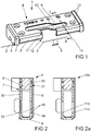
- Figure 1 shows a closure 1 for a window with a sash 3 pivotable against a frame 2.
- the frame 2 and the wing 3 are shown only schematically in the drawing.
- the lock 1 has a locking plate 4 attached to the frame 2 and a locking pin 5 which is longitudinally displaceable on the wing 3.
- the locking plate 4 is designed in two parts with a base part 6 resting on the frame 2 and a head part 7 connected to the base part 6.
- the base part 6 is made of plastic, while the head part 7 is bent and punched in a U-shape from sheet steel.
- the head part 7 has a base 8 and two legs 9, 10 protruding from the base 8.
- the two legs 9, 10 each have an inlet opening 11, 12 for the locking pin 5.
- the locking plate 4 has mounting recesses 13 for the implementation of mounting screws, not shown.
- the fastening recesses 13 penetrate the legs 9, 10 of the head part 7 and the base part 6.
- the inlet openings 11, 12 are connected to one another via the base 8 and lead to the retaining edge 14 and to Figure 2 retaining edge 15 shown, which support the locking pin 5 in the closed state of the lock 1.
- FIG. 1 in a sectional view through the strike plate 4
- the two legs 9, 10 each have retaining edges 14, 15 for the locking pin 5.
- the retaining edge 14 of one leg 9 or the retaining edge 15 acts optionally of the other leg 10 with the locking pin 5 together.
- the base part 6 has latching hooks 16 for engaging behind latching recesses 17 of the head part 7.
- the strike plate 4 can thus be latched in a pre-assembly.
- the retaining edges 14, 15 of the embodiment of the strike plate 4 have bevels 18, which enable the inserted locking pin 5 to tilt. A window equipped with this lock 1 can thus be moved into a tilted position.
- FIG 2a shows a further embodiment of a strike plate 104 in a sectional view which extends from the Figure 2 only differs in that retaining edges 114, 115 are designed with sharp edges. As a result, the locking pin 5 is reliably supported in a closed position.
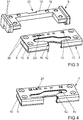
- FIG 3 shows the strike plate 4 from Figure 1 before assembly.
- the base part 6 has a web 19 which connects the legs 9, 10 to the inlet opening 11, 12 supports facing away from the side.
- the legs 9, 10 also have insertion bevels 20 to simplify the insertion of the head part 7 into the base part 6.
- the base part 6 has support feet 21 for support on the frame 2 of the window and a recess 22 for attaching a lever tool to separate the head part 7 from the base part 6.
- the head part 7 is provided with a marking "RS" 23 and is thus in this assembly position intended for use in a right-hinged window.
- Figure 4 shows the head part 7 Figure 3 in a view from below of the other leg 10.
- This leg 10 is provided with a marking “LS” 24. If the head part 7 is mounted with this leg 10 in such a way that the marking “LS” is visible, the strike plate 4 can be inserted in a window hinged on the left.
- FIG 5 shows a further embodiment of a strike plate 204 in a plan view. It can be seen here that inlet openings 211, 212 are arranged laterally on the strike plate 204. Otherwise, the striking plate 204 is like that from the Figures 1 to 4 built up.
- the strike plate 204 has different legs 209, 210 with differently designed retaining edges 214, 215.
Landscapes
- Engineering & Computer Science (AREA)
- Mechanical Engineering (AREA)
- Hinges (AREA)
Abstract
Description
- Die Erfindung betrifft ein Schließblech für einen Treibstangenbeschlag eines Fensters, einer Fenstertür oder dergleichen, mit einem Grundteil und mit einem mit dem Grundteil verbundenen Kopfteil und mit zumindest einer im Kopfteil angeordneten Haltekante zur Abstützung eines Schließzapfens des Treibstangenbeschlages, wobei das Kopfteil im Querschnitt U-förmig mit einer Basis und zwei von der Basis abstehenden Schenkeln gestaltet ist.
- Ein solches Schließblech ist beispielsweise aus der
EP 3 441 547 A1 bekannt. Das Grundteil hat eine Stütze für das Kopfteil. Verschraubungen des Schließblechs mit dem Fenster sind durch die beiden Schenkel des U-förmigen Kopfteils und durch die Stütze des Fußteils geführt. Das Schließblech hat hierdurch eine besonders hohe Stabilität und lässt sich einfach auf verschiedene Fenster anpassen. Beispielsweise lässt sich das Kopfteil bei einem links anschlagenden Fenster einfach gegen ein Kopfteil eines rechts anschlagenden Fensters austauschen. Ebenso kann das Kopfteil ausgetauscht werden, wenn beispielsweise anstelle einer Kippstellung des Fensters eine Spaltlüftungsstellung gewünscht wird, was eine andere Lage und/oder eine andere Geometrie der Haltekante erfordert. - Der Erfindung liegt das Problem zugrunde, ein Schließblech der eingangs genannten Art so weiter zu bilden, dass es noch einfacher für verschiedene Fenster angepasst werden kann.
- Dieses Problem wird erfindungsgemäß dadurch gelöst, dass beide Schenkel jeweils Haltekanten aufweisen und dass das Kopfteil wahlweise mit dem einen Schenkel oder dem anderem Schenkel in eine mit dem Schließzapfen zusammenwirkende Position montierbar ist.
- Durch diese Gestaltung hat auch der zweite Schenkel Haltekanten, welche in Abhängigkeit von der Montagestellung des Kopfteils mit dem Schließzapfen zusammenwirken. Dank der Erfindung ist das Kopfteil derart montierbar, so dass in Abhängigkeit von dem montierten Zustand dem Schließzapfen verschiedene Haltekanten gegenüberstehen. Durch diese Gestaltung lässt sich das Kopfteil mit dem einen Schenkel für links anschlagende Fenster und mit dem anderen Schenkel für rechts anschlagende Fenster vorbereiten. Hierdurch lässt sich das Schließblech noch einfacher für verschiedene Fenster anpassen, weil das Kopfteil eine Anpassung durch seine Montagestellung auf dem Grundteil ermöglicht.
- Ein mittiges Einführen des Schließzapfens in das Schließblech gestaltet sich in jeder Montageposition besonders einfach, wenn beide Schenkel jeweils eine Einlauföffnung aufweisen.
- Eine Trennung der beiden Einlauföffnungen durch einen parallel zu den Haltekanten verlaufenden Steg könnte zu engen Toleranzen führen. Enge Toleranzen des Schließblechs im montierten Zustand lassen sich gemäß einer anderen vorteilhaften Weiterbildung der Erfindung vermeiden, wenn die Einlauföffnungen der beiden Schenkel über die Basis miteinander verbunden sind.
- Ein seitliches Einführen des Schließzapfens in das Schließblech wird gemäß einer anderen vorteilhaften Weiterbildung der Erfindung ermöglicht, wenn Einlauföffnungen auf einander gegenüberliegenden Enden des Schließblechs angeordnet sind.
- Die Montage des Schließblechs an dem Fenster, der Fenstertür oder dergleichen gestaltet sich gemäß einer anderen vorteilhaften Weiterbildung der Erfindung besonders einfach, wenn das Grundteil einen Steg zur Abstützung der beiden Schenkel des Kopfteils und Stützfüße zur Abstützung an einem angrenzenden Bauteil des Fensters, der Fenstertür oder dergleichen hat.
- Das Schließblech lässt sich gemäß einer anderen vorteilhaften Weiterbildung der Erfindung einfach vormontieren, wenn das Grundteil und das Kopfteil miteinander korrespondierende Rastausnehmungen und Rasthaken zur Verrasterung aufweisen. Ein weiterer Vorteil dieser Gestaltung besteht darin, dass die Gefahr von Verwechselungen der möglichen Montagepositionen des Kopfteils bei der Endmontage am Fenster, der Fenstertür oder dergleichen vermieden wird.
- Das mit dem Grundteil verrastete Kopfteil lässt sich gemäß einer anderen vorteilhaften Weiterbildung der Erfindung einfach demontieren, wenn das Grundteil eine Ausnehmung zum Ansetzen eines Hebelwerkzeugs aufweist. Dies trägt zur weiteren Vereinfachung der Montage bei.
- Das Schließblech weist gemäß einer anderen vorteilhaften Weiterbildung der Erfindung im montierten Zustand eine besonders hohe Stabilität auf, wenn die Schenkel einander fluchtende Befestigungsausnehmungen zur Durchführung von Befestigungsschrauben haben.
- Ein versehentliches fehlerhaftes Montieren des Kopfteils an dem Fußteil lässt sich gemäß einer anderen vorteilhaften Weiterbildung der Erfindung vermeiden, wenn die Schenkel auf ihren voneinander abgewandten Seiten Markierungen zur Kennzeichnung der Montageposition aufweisen. Durch diese Gestaltung können die Schenkel beispielsweise für rechts und links anschlagende Fenster unterschiedlich markiert werden. Hierdurch lässt sich mit einem Blick feststellen, ob das Schließblech mit der vorgesehenen Haltekante für das jeweilige Fenster richtig montiert ist.
- Die Erfindung lässt zahlreiche Ausführungsformen zu. Zur weiteren Verdeutlichung ihres Grundprinzips sind mehrere davon in der Zeichnung dargestellt und werden nachfolgend beschrieben. Diese zeigt in
- Fig.1
- perspektivisch einen Verschluss eines Treibstangenbeschlages mit einem Schließblech,
- Fig.2
- eine Schnittdarstellung durch das Schließblech aus
Figur 1 entlang der Linie II - II, - Fig.2a
- eine weitere Ausführungsform des Schließblechs in einer Schnittdarstellung,
- Fig.3
- ein Kopfteil und ein Grundteil des Schließblechs aus
Figur 1 vor der Montage, - Fig.4
- eine Ansicht des Kopfteils des Schließblechs aus
Figur 3 von unten, - Fig.5
- eine weitere Ausführungsform des Schließblechs.
-
Figur 1 zeigt einen Verschluss 1 für ein gegen einen Rahmen 2 schwenkbaren Flügel 3 aufweisendes Fenster. Der Rahmen 2 und der Flügel 3 sind in der Zeichnung nur schematisch dargestellt. Der Verschluss 1 hat ein an dem Rahmen 2 befestigtes Schließblech 4 und einen längsverschieblich an dem Flügel 3 geführten Schließzapfen 5. Das Schließblech 4 ist mit einem am Rahmen 2 anliegenden Grundteil 6 und einem mit dem Grundteil 6 verbundenen Kopfteil 7 zweiteilig gestaltet. Das Grundteil 6 ist aus Kunststoff gefertigt, während das Kopfteil 7 aus Stahlblech U-förmig gebogen und gestanzt ist. Das Kopfteil 7 hat eine Basis 8 und zwei von der Basis 8 abstehende Schenkel 9, 10. Die beiden Schenkel 9, 10 haben jeweils eine Einlauföffnung 11, 12 für den Schließzapfen 5. Das Schließblech 4 hat Befestigungsausnehmungen 13 zur Durchführung von nicht dargestellten Befestigungsschrauben. Die Befestigungsausnehmungen 13 durchdringen die Schenkel 9, 10 des Kopfteils 7 und das Grundteil 6. Die Einlauföffnungen 11, 12 sind über die Basis 8 miteinander verbunden und führen zur Haltekante 14 und zurFigur 2 dargestellten Haltekante 15, welche den Schließzapfen 5 im geschlossenen Zustand des Verschlusses 1 abstützen. - Wie
Figur 2 in einer Schnittdarstellung durch das Schließblech 4 ausFigur 1 entlang der Linie II - II zeigt, haben die beiden Schenkel 9, 10 jeweils Haltekanten 14, 15 für den Schließzapfen 5. In Abhängigkeit von der Montagestellung des Kopfteils 7 an dem Grundteil 6 wirkt wahlweise die Haltekante 14 des einen Schenkels 9 oder die Haltekante 15 des anderen Schenkels 10 mit dem Schließzapfen 5 zusammen. Das Grundteil 6 hat Rasthaken 16 zur Hintergreifung von Rastausnehmungen 17 des Kopfteils 7. Damit lässt sich das Schließblech 4 in einer Vormontage verrasten. Die Haltekanten 14, 15 der Ausführungsform des Schließblechs 4 haben Schrägen 18, welches dem eingeführten Schließzapfen 5 ein Kippen ermöglicht. Damit lässt sich ein mit diesem Verschluss 1 ausgestattetes Fenster in eine Kippstellung bewegen. -
Figur 2a zeigt eine weitere Ausführungsform eines Schließblechs 104 in einer Schnittdarstellung, welches sich von dem ausFigur 2 nur dadurch unterscheidet, dass Haltekanten 114, 115 scharfkantig gestaltet sind. Hierdurch wird der Schließzapfen 5 in einer Schließstellung zuverlässig abgestützt. -
Figur 3 zeigt das Schließblech 4 ausFigur 1 vor der Montage. Hierbei ist zu erkennen, dass das Grundteil 6 einen Steg 19 hat, welcher die Schenkel 9, 10 an der der Einlauföffnung 11, 12 abgewandten Seite abstützt. Die Schenkel 9, 10 weisen zudem Einführschrägen 20 zur Vereinfachung des Einführens des Kopfteils 7 in das Grundteil 6 auf. Das Grundteil 6 hat Stützfüße 21 zur Abstützung an dem Rahmen 2 des Fensters und eine Ausnehmung 22 zum Ansetzen eines Hebelwerkzeugs zur Trennung des Kopfteils 7 von dem Grundteil 6. Das Kopfteil 7 ist mit einer Markierung "RS" 23 versehen und ist damit in dieser Montageposition für den Einsatz in einem rechts anschlagenden Fenster vorgesehen. -
Figur 4 zeigt das Kopfteil 7 ausFigur 3 in einer Ansicht von unten auf den anderen Schenkel 10. Dieser Schenkel 10 ist mit einer Markierung "LS" 24 versehen. Wird das Kopfteil 7 mit diesem Schenkel 10 derart montiert, dass die Markierung "LS" sichtbar ist, kann das Schließblech 4 in einem links anschlagenden Fenster eingesetzt werden. -
Figur 5 zeigt eine weitere Ausführungsform eines Schließblechs 204 in einer Draufsicht. Hierbei ist zu erkennen, dass Einlauföffnungen 211, 212 seitlich an dem Schließblech 204 angeordnet sind. Ansonsten ist das Schließblech 204 wie das aus denFiguren 1 bis 4 aufgebaut. Das Schließblech 204 hat unterschiedliche Schenkel 209, 210 mit unterschiedlich gestalteten Haltekanten 214, 215.
Claims (9)
- Schließblech (4, 104, 204) für einen Treibstangenbeschlag eines Fensters, einer Fenstertür oder dergleichen, mit einem Grundteil (6) und mit einem mit dem Grundteil (6) verbundenen Kopfteil (7) und mit zumindest einer im Kopfteil (7) angeordneten Haltekante (14, 15, 114, 115) zur Abstützung eines Schließzapfens (5) des Treibstangenbeschlages, wobei das Kopfteil (7) im Querschnitt U-förmig mit einer Basis (8) und zwei von der Basis (8) abstehenden Schenkeln (9, 10, 209, 210) gestaltet ist, dadurch gekennzeichnet, dass beide Schenkel (9, 10) jeweils Haltekanten (14, 15, 114, 115, 214, 215) aufweisen und dass das Kopfteil (7) wahlweise mit dem einen Schenkel (9, 209) oder dem anderem Schenkel (10, 210) in eine mit dem Schließzapfen (5) zusammenwirkende Position montierbar ist.
- Schließblech nach Anspruch 1, dadurch gekennzeichnet, dass beide Schenkel (9, 10) jeweils eine Einlauföffnung (11, 12, 211, 212) aufweisen.
- Schließblech nach Anspruch 1 oder 2, dadurch gekennzeichnet, dass die Einlauföffnungen (11, 12) der beiden Schenkel (9, 10) über die Basis (8) miteinander verbunden sind.
- Schließblech nach Anspruch 1 oder 2, dadurch gekennzeichnet, dass Einlauföffnungen (211, 212) auf einander gegenüberliegenden Enden des Schließblechs (204) angeordnet sind.
- Schließblech nach zumindest einem der Ansprüche 1 bis 4, dadurch gekennzeichnet, dass das Grundteil (6) einen Steg (19) zur Abstützung der beiden Schenkel (9, 10) des Kopfteils (7) und Stützfüße (21) zur Abstützung an einem angrenzenden Bauteil des Fensters, der Fenstertür oder dergleichen hat.
- Schließblech nach zumindest einem der Ansprüche 1 bis 5, dadurch gekennzeichnet, dass das Grundteil (6) und das Kopfteil (7) miteinander korrespondierende Rastausnehmungen (17) und Rasthaken (16) zur Verrasterung aufweisen.
- Schließblech nach zumindest einem der Ansprüche 1 bis 6, dadurch gekennzeichnet, dass das Grundteil (6) eine Ausnehmung (22) zum Ansetzen eines Hebelwerkzeugs aufweist.
- Schließblech nach zumindest einem der Ansprüche 1 bis 7, dadurch gekennzeichnet, dass die Schenkel (9, 10) einander fluchtende Befestigungsausnehmungen (13) zur Durchführung von Befestigungsschrauben haben.
- Schließblech nach zumindest einem der Ansprüche 1 bis 8, dadurch gekennzeichnet, dass die Schenkel (9, 10) auf ihren voneinander abgewandten Seiten Markierungen (23, 24) zur Kennzeichnung der Montageposition aufweisen.
Priority Applications (1)
| Application Number | Priority Date | Filing Date | Title |
|---|---|---|---|
| PL20182409T PL3760818T3 (pl) | 2019-07-04 | 2020-06-26 | Blacha zaczepowa do okucia zasuwnicy |
Applications Claiming Priority (1)
| Application Number | Priority Date | Filing Date | Title |
|---|---|---|---|
| DE102019209860.6A DE102019209860A1 (de) | 2019-07-04 | 2019-07-04 | SCHLIEßBLECH FÜR EINEN TREIBSTANGENBESCHLAG |
Publications (2)
| Publication Number | Publication Date |
|---|---|
| EP3760818A1 true EP3760818A1 (de) | 2021-01-06 |
| EP3760818B1 EP3760818B1 (de) | 2022-01-12 |
Family
ID=71170371
Family Applications (1)
| Application Number | Title | Priority Date | Filing Date |
|---|---|---|---|
| EP20182409.1A Active EP3760818B1 (de) | 2019-07-04 | 2020-06-26 | Schliessblech fuer einen treibstangenbeschlag |
Country Status (3)
| Country | Link |
|---|---|
| EP (1) | EP3760818B1 (de) |
| DE (1) | DE102019209860A1 (de) |
| PL (1) | PL3760818T3 (de) |
Cited By (2)
| Publication number | Priority date | Publication date | Assignee | Title |
|---|---|---|---|---|
| US20230022439A1 (en) * | 2019-12-06 | 2023-01-26 | Emka Beschlagteile Gmbh & Co. Kg | Catch |
| WO2025087827A1 (de) | 2023-10-25 | 2025-05-01 | Aug. Winkhaus SE & Co. KG | SCHLIEßBLECH |
Citations (3)
| Publication number | Priority date | Publication date | Assignee | Title |
|---|---|---|---|---|
| DE1935885U (de) * | 1966-01-25 | 1966-03-31 | Jaeger Frank K G | Schliessgehaeuse fuer zum verriegeln der fluegel von fenstern, tueren od. dgl. dienende kantengetriebe. |
| GB2424448A (en) * | 2005-03-21 | 2006-09-27 | Kenrick & Sons Ltd | Reversible keep |
| EP3441547A1 (de) | 2017-08-10 | 2019-02-13 | Aug. Winkhaus GmbH & Co. KG | Schliessblech für einen treibstangenbeschlag |
-
2019
- 2019-07-04 DE DE102019209860.6A patent/DE102019209860A1/de not_active Withdrawn
-
2020
- 2020-06-26 PL PL20182409T patent/PL3760818T3/pl unknown
- 2020-06-26 EP EP20182409.1A patent/EP3760818B1/de active Active
Patent Citations (3)
| Publication number | Priority date | Publication date | Assignee | Title |
|---|---|---|---|---|
| DE1935885U (de) * | 1966-01-25 | 1966-03-31 | Jaeger Frank K G | Schliessgehaeuse fuer zum verriegeln der fluegel von fenstern, tueren od. dgl. dienende kantengetriebe. |
| GB2424448A (en) * | 2005-03-21 | 2006-09-27 | Kenrick & Sons Ltd | Reversible keep |
| EP3441547A1 (de) | 2017-08-10 | 2019-02-13 | Aug. Winkhaus GmbH & Co. KG | Schliessblech für einen treibstangenbeschlag |
Cited By (3)
| Publication number | Priority date | Publication date | Assignee | Title |
|---|---|---|---|---|
| US20230022439A1 (en) * | 2019-12-06 | 2023-01-26 | Emka Beschlagteile Gmbh & Co. Kg | Catch |
| US12540487B2 (en) * | 2019-12-06 | 2026-02-03 | Emka Beschlagteile Gmbh & Co. Kg | Catch |
| WO2025087827A1 (de) | 2023-10-25 | 2025-05-01 | Aug. Winkhaus SE & Co. KG | SCHLIEßBLECH |
Also Published As
| Publication number | Publication date |
|---|---|
| EP3760818B1 (de) | 2022-01-12 |
| PL3760818T3 (pl) | 2022-03-28 |
| DE102019209860A1 (de) | 2021-01-07 |
Similar Documents
| Publication | Publication Date | Title |
|---|---|---|
| EP3238569B1 (de) | Vorrichtung zur anbringung einer rückwand an ein bewegbares möbelteil | |
| EP2546438B1 (de) | Zur verschieblichen Montage in einer einen Hinterschnitt aufweisenden Beschlagnut vorgesehenes Beschlagteil | |
| DE69612273T2 (de) | Mehrpunkt-Verriegelungsstruktur für einen Verschlussmechanismus mit Gleitschiene | |
| EP3760818B1 (de) | Schliessblech fuer einen treibstangenbeschlag | |
| CH663983A5 (de) | Treibstangenbeschlag fuer fenster oder tueren. | |
| AT507493B1 (de) | Laufrolle für einen schiebeflügel | |
| WO2017001226A1 (de) | Absenkdichtung | |
| DE102015206905A1 (de) | Getriebebeschlag sowie Fenster, Tür oder dergleichen mit einem Getriebebeschlag | |
| EP2754804B1 (de) | Verschluss für einen Treibstangenbeschlag | |
| EP3293330B1 (de) | Verschluss für einen treibstangenbeschlag | |
| EP2099989B1 (de) | Treibstangengetriebe | |
| WO2008119451A1 (de) | Beschlag für ein fenster, eine tür oder dergleichen | |
| DE19758907B4 (de) | Einen Überschlag aufweisender Flügel eines Fensters, einer Tür oder dergleichen, mit einem Scharnierbeschlag sowie Montageverfahren des Scharnierbeschlags | |
| EP3441547B1 (de) | Schliessblech für einen treibstangenbeschlag | |
| EP2132391B1 (de) | Treibstangenanordnung mit mindestens einer treibstange und mindestens einem treibstangenführungselement | |
| DE202014104461U1 (de) | Anordnung zum Positionieren eines Griffs | |
| EP0006439B2 (de) | Vorrichtung zur Stossstellenüberlappung an Stulpschienen | |
| DE102016004915B3 (de) | Beschlag für ein Fenster, Verfahren zum Herstellen des Beschlags sowie entsprechendes Fenster | |
| EP1757760B1 (de) | Beschlagteil für einen Treibstangenbeschlag | |
| DE2366635C2 (de) | Stulpschienen-Eckverbindung | |
| DE202007011079U1 (de) | Ausstellvorrichtung | |
| EP1944442B1 (de) | Treibstangengetriebe und Fenster oder Tür mit einem Treibstangengetriebe | |
| DE2421643B2 (de) | Schließstück für Fenster- und Türverschlüsse o.dgl | |
| DE8323366U1 (de) | Vorrichtung zur stossstellenueberlappung zwischen den einander zugewendeten enden zweier stulpschienen von beschlagelementen | |
| DE10100924A1 (de) | Gestängekupplung |
Legal Events
| Date | Code | Title | Description |
|---|---|---|---|
| PUAI | Public reference made under article 153(3) epc to a published international application that has entered the european phase |
Free format text: ORIGINAL CODE: 0009012 |
|
| STAA | Information on the status of an ep patent application or granted ep patent |
Free format text: STATUS: THE APPLICATION HAS BEEN PUBLISHED |
|
| AK | Designated contracting states |
Kind code of ref document: A1 Designated state(s): AL AT BE BG CH CY CZ DE DK EE ES FI FR GB GR HR HU IE IS IT LI LT LU LV MC MK MT NL NO PL PT RO RS SE SI SK SM TR |
|
| AX | Request for extension of the european patent |
Extension state: BA ME |
|
| STAA | Information on the status of an ep patent application or granted ep patent |
Free format text: STATUS: REQUEST FOR EXAMINATION WAS MADE |
|
| 17P | Request for examination filed |
Effective date: 20210609 |
|
| RBV | Designated contracting states (corrected) |
Designated state(s): AL AT BE BG CH CY CZ DE DK EE ES FI FR GB GR HR HU IE IS IT LI LT LU LV MC MK MT NL NO PL PT RO RS SE SI SK SM TR |
|
| GRAP | Despatch of communication of intention to grant a patent |
Free format text: ORIGINAL CODE: EPIDOSNIGR1 |
|
| STAA | Information on the status of an ep patent application or granted ep patent |
Free format text: STATUS: GRANT OF PATENT IS INTENDED |
|
| INTG | Intention to grant announced |
Effective date: 20210823 |
|
| GRAS | Grant fee paid |
Free format text: ORIGINAL CODE: EPIDOSNIGR3 |
|
| GRAA | (expected) grant |
Free format text: ORIGINAL CODE: 0009210 |
|
| STAA | Information on the status of an ep patent application or granted ep patent |
Free format text: STATUS: THE PATENT HAS BEEN GRANTED |
|
| AK | Designated contracting states |
Kind code of ref document: B1 Designated state(s): AL AT BE BG CH CY CZ DE DK EE ES FI FR GB GR HR HU IE IS IT LI LT LU LV MC MK MT NL NO PL PT RO RS SE SI SK SM TR |
|
| REG | Reference to a national code |
Ref country code: GB Ref legal event code: FG4D Free format text: NOT ENGLISH |
|
| REG | Reference to a national code |
Ref country code: CH Ref legal event code: EP |
|
| REG | Reference to a national code |
Ref country code: DE Ref legal event code: R096 Ref document number: 502020000546 Country of ref document: DE |
|
| REG | Reference to a national code |
Ref country code: IE Ref legal event code: FG4D Free format text: LANGUAGE OF EP DOCUMENT: GERMAN |
|
| REG | Reference to a national code |
Ref country code: AT Ref legal event code: REF Ref document number: 1462493 Country of ref document: AT Kind code of ref document: T Effective date: 20220215 |
|
| REG | Reference to a national code |
Ref country code: LT Ref legal event code: MG9D |
|
| REG | Reference to a national code |
Ref country code: NL Ref legal event code: MP Effective date: 20220112 |
|
| PG25 | Lapsed in a contracting state [announced via postgrant information from national office to epo] |
Ref country code: NL Free format text: LAPSE BECAUSE OF FAILURE TO SUBMIT A TRANSLATION OF THE DESCRIPTION OR TO PAY THE FEE WITHIN THE PRESCRIBED TIME-LIMIT Effective date: 20220112 |
|
| PG25 | Lapsed in a contracting state [announced via postgrant information from national office to epo] |
Ref country code: SE Free format text: LAPSE BECAUSE OF FAILURE TO SUBMIT A TRANSLATION OF THE DESCRIPTION OR TO PAY THE FEE WITHIN THE PRESCRIBED TIME-LIMIT Effective date: 20220112 Ref country code: RS Free format text: LAPSE BECAUSE OF FAILURE TO SUBMIT A TRANSLATION OF THE DESCRIPTION OR TO PAY THE FEE WITHIN THE PRESCRIBED TIME-LIMIT Effective date: 20220112 Ref country code: PT Free format text: LAPSE BECAUSE OF FAILURE TO SUBMIT A TRANSLATION OF THE DESCRIPTION OR TO PAY THE FEE WITHIN THE PRESCRIBED TIME-LIMIT Effective date: 20220512 Ref country code: NO Free format text: LAPSE BECAUSE OF FAILURE TO SUBMIT A TRANSLATION OF THE DESCRIPTION OR TO PAY THE FEE WITHIN THE PRESCRIBED TIME-LIMIT Effective date: 20220412 Ref country code: LT Free format text: LAPSE BECAUSE OF FAILURE TO SUBMIT A TRANSLATION OF THE DESCRIPTION OR TO PAY THE FEE WITHIN THE PRESCRIBED TIME-LIMIT Effective date: 20220112 Ref country code: HR Free format text: LAPSE BECAUSE OF FAILURE TO SUBMIT A TRANSLATION OF THE DESCRIPTION OR TO PAY THE FEE WITHIN THE PRESCRIBED TIME-LIMIT Effective date: 20220112 Ref country code: ES Free format text: LAPSE BECAUSE OF FAILURE TO SUBMIT A TRANSLATION OF THE DESCRIPTION OR TO PAY THE FEE WITHIN THE PRESCRIBED TIME-LIMIT Effective date: 20220112 Ref country code: BG Free format text: LAPSE BECAUSE OF FAILURE TO SUBMIT A TRANSLATION OF THE DESCRIPTION OR TO PAY THE FEE WITHIN THE PRESCRIBED TIME-LIMIT Effective date: 20220412 |
|
| PG25 | Lapsed in a contracting state [announced via postgrant information from national office to epo] |
Ref country code: LV Free format text: LAPSE BECAUSE OF FAILURE TO SUBMIT A TRANSLATION OF THE DESCRIPTION OR TO PAY THE FEE WITHIN THE PRESCRIBED TIME-LIMIT Effective date: 20220112 Ref country code: GR Free format text: LAPSE BECAUSE OF FAILURE TO SUBMIT A TRANSLATION OF THE DESCRIPTION OR TO PAY THE FEE WITHIN THE PRESCRIBED TIME-LIMIT Effective date: 20220413 Ref country code: FI Free format text: LAPSE BECAUSE OF FAILURE TO SUBMIT A TRANSLATION OF THE DESCRIPTION OR TO PAY THE FEE WITHIN THE PRESCRIBED TIME-LIMIT Effective date: 20220112 |
|
| PG25 | Lapsed in a contracting state [announced via postgrant information from national office to epo] |
Ref country code: IS Free format text: LAPSE BECAUSE OF FAILURE TO SUBMIT A TRANSLATION OF THE DESCRIPTION OR TO PAY THE FEE WITHIN THE PRESCRIBED TIME-LIMIT Effective date: 20220512 |
|
| REG | Reference to a national code |
Ref country code: DE Ref legal event code: R097 Ref document number: 502020000546 Country of ref document: DE |
|
| PG25 | Lapsed in a contracting state [announced via postgrant information from national office to epo] |
Ref country code: SM Free format text: LAPSE BECAUSE OF FAILURE TO SUBMIT A TRANSLATION OF THE DESCRIPTION OR TO PAY THE FEE WITHIN THE PRESCRIBED TIME-LIMIT Effective date: 20220112 Ref country code: SK Free format text: LAPSE BECAUSE OF FAILURE TO SUBMIT A TRANSLATION OF THE DESCRIPTION OR TO PAY THE FEE WITHIN THE PRESCRIBED TIME-LIMIT Effective date: 20220112 Ref country code: RO Free format text: LAPSE BECAUSE OF FAILURE TO SUBMIT A TRANSLATION OF THE DESCRIPTION OR TO PAY THE FEE WITHIN THE PRESCRIBED TIME-LIMIT Effective date: 20220112 Ref country code: EE Free format text: LAPSE BECAUSE OF FAILURE TO SUBMIT A TRANSLATION OF THE DESCRIPTION OR TO PAY THE FEE WITHIN THE PRESCRIBED TIME-LIMIT Effective date: 20220112 Ref country code: DK Free format text: LAPSE BECAUSE OF FAILURE TO SUBMIT A TRANSLATION OF THE DESCRIPTION OR TO PAY THE FEE WITHIN THE PRESCRIBED TIME-LIMIT Effective date: 20220112 Ref country code: CZ Free format text: LAPSE BECAUSE OF FAILURE TO SUBMIT A TRANSLATION OF THE DESCRIPTION OR TO PAY THE FEE WITHIN THE PRESCRIBED TIME-LIMIT Effective date: 20220112 |
|
| PLBE | No opposition filed within time limit |
Free format text: ORIGINAL CODE: 0009261 |
|
| STAA | Information on the status of an ep patent application or granted ep patent |
Free format text: STATUS: NO OPPOSITION FILED WITHIN TIME LIMIT |
|
| PG25 | Lapsed in a contracting state [announced via postgrant information from national office to epo] |
Ref country code: AL Free format text: LAPSE BECAUSE OF FAILURE TO SUBMIT A TRANSLATION OF THE DESCRIPTION OR TO PAY THE FEE WITHIN THE PRESCRIBED TIME-LIMIT Effective date: 20220112 |
|
| 26N | No opposition filed |
Effective date: 20221013 |
|
| PG25 | Lapsed in a contracting state [announced via postgrant information from national office to epo] |
Ref country code: MC Free format text: LAPSE BECAUSE OF FAILURE TO SUBMIT A TRANSLATION OF THE DESCRIPTION OR TO PAY THE FEE WITHIN THE PRESCRIBED TIME-LIMIT Effective date: 20220112 |
|
| REG | Reference to a national code |
Ref country code: BE Ref legal event code: MM Effective date: 20220630 |
|
| PG25 | Lapsed in a contracting state [announced via postgrant information from national office to epo] |
Ref country code: SI Free format text: LAPSE BECAUSE OF FAILURE TO SUBMIT A TRANSLATION OF THE DESCRIPTION OR TO PAY THE FEE WITHIN THE PRESCRIBED TIME-LIMIT Effective date: 20220112 |
|
| PG25 | Lapsed in a contracting state [announced via postgrant information from national office to epo] |
Ref country code: LU Free format text: LAPSE BECAUSE OF NON-PAYMENT OF DUE FEES Effective date: 20220626 Ref country code: IE Free format text: LAPSE BECAUSE OF NON-PAYMENT OF DUE FEES Effective date: 20220626 |
|
| PG25 | Lapsed in a contracting state [announced via postgrant information from national office to epo] |
Ref country code: BE Free format text: LAPSE BECAUSE OF NON-PAYMENT OF DUE FEES Effective date: 20220630 |
|
| P01 | Opt-out of the competence of the unified patent court (upc) registered |
Effective date: 20230516 |
|
| PG25 | Lapsed in a contracting state [announced via postgrant information from national office to epo] |
Ref country code: IT Free format text: LAPSE BECAUSE OF FAILURE TO SUBMIT A TRANSLATION OF THE DESCRIPTION OR TO PAY THE FEE WITHIN THE PRESCRIBED TIME-LIMIT Effective date: 20220112 |
|
| REG | Reference to a national code |
Ref country code: CH Ref legal event code: PL |
|
| PG25 | Lapsed in a contracting state [announced via postgrant information from national office to epo] |
Ref country code: MK Free format text: LAPSE BECAUSE OF FAILURE TO SUBMIT A TRANSLATION OF THE DESCRIPTION OR TO PAY THE FEE WITHIN THE PRESCRIBED TIME-LIMIT Effective date: 20220112 Ref country code: CY Free format text: LAPSE BECAUSE OF FAILURE TO SUBMIT A TRANSLATION OF THE DESCRIPTION OR TO PAY THE FEE WITHIN THE PRESCRIBED TIME-LIMIT Effective date: 20220112 Ref country code: CH Free format text: LAPSE BECAUSE OF NON-PAYMENT OF DUE FEES Effective date: 20230630 |
|
| PG25 | Lapsed in a contracting state [announced via postgrant information from national office to epo] |
Ref country code: HU Free format text: LAPSE BECAUSE OF FAILURE TO SUBMIT A TRANSLATION OF THE DESCRIPTION OR TO PAY THE FEE WITHIN THE PRESCRIBED TIME-LIMIT; INVALID AB INITIO Effective date: 20200626 |
|
| PG25 | Lapsed in a contracting state [announced via postgrant information from national office to epo] |
Ref country code: TR Free format text: LAPSE BECAUSE OF FAILURE TO SUBMIT A TRANSLATION OF THE DESCRIPTION OR TO PAY THE FEE WITHIN THE PRESCRIBED TIME-LIMIT Effective date: 20220112 |
|
| PG25 | Lapsed in a contracting state [announced via postgrant information from national office to epo] |
Ref country code: MT Free format text: LAPSE BECAUSE OF FAILURE TO SUBMIT A TRANSLATION OF THE DESCRIPTION OR TO PAY THE FEE WITHIN THE PRESCRIBED TIME-LIMIT Effective date: 20220112 |
|
| REG | Reference to a national code |
Ref country code: DE Ref legal event code: R081 Ref document number: 502020000546 Country of ref document: DE Owner name: AUG. WINKHAUS SE & CO. KG, DE Free format text: FORMER OWNER: AUG. WINKHAUS GMBH & CO. KG, 48291 TELGTE, DE Ref country code: DE Ref legal event code: R081 Ref document number: 502020000546 Country of ref document: DE Owner name: AUG. WINKHAUS SE, DE Free format text: FORMER OWNER: AUG. WINKHAUS GMBH & CO. KG, 48291 TELGTE, DE |
|
| GBPC | Gb: european patent ceased through non-payment of renewal fee |
Effective date: 20240626 |
|
| PG25 | Lapsed in a contracting state [announced via postgrant information from national office to epo] |
Ref country code: GB Free format text: LAPSE BECAUSE OF NON-PAYMENT OF DUE FEES Effective date: 20240626 |
|
| PGFP | Annual fee paid to national office [announced via postgrant information from national office to epo] |
Ref country code: PL Payment date: 20250618 Year of fee payment: 6 Ref country code: DE Payment date: 20250618 Year of fee payment: 6 |
|
| PGFP | Annual fee paid to national office [announced via postgrant information from national office to epo] |
Ref country code: FR Payment date: 20250618 Year of fee payment: 6 |
|
| PGFP | Annual fee paid to national office [announced via postgrant information from national office to epo] |
Ref country code: AT Payment date: 20250616 Year of fee payment: 6 |
|
| REG | Reference to a national code |
Ref country code: DE Ref legal event code: R081 Ref document number: 502020000546 Country of ref document: DE Owner name: AUG. WINKHAUS SE, DE Free format text: FORMER OWNER: AUG. WINKHAUS SE & CO. KG, 48291 TELGTE, DE |