EP3760746B1 - Grain-oriented electrical steel sheet - Google Patents
Grain-oriented electrical steel sheet Download PDFInfo
- Publication number
- EP3760746B1 EP3760746B1 EP19758237.2A EP19758237A EP3760746B1 EP 3760746 B1 EP3760746 B1 EP 3760746B1 EP 19758237 A EP19758237 A EP 19758237A EP 3760746 B1 EP3760746 B1 EP 3760746B1
- Authority
- EP
- European Patent Office
- Prior art keywords
- steel sheet
- grain
- oriented electrical
- electrical steel
- groove
- Prior art date
- Legal status (The legal status is an assumption and is not a legal conclusion. Google has not performed a legal analysis and makes no representation as to the accuracy of the status listed.)
- Active
Links
Images


Classifications
-
- H—ELECTRICITY
- H01—ELECTRIC ELEMENTS
- H01F—MAGNETS; INDUCTANCES; TRANSFORMERS; SELECTION OF MATERIALS FOR THEIR MAGNETIC PROPERTIES
- H01F1/00—Magnets or magnetic bodies characterised by the magnetic materials therefor; Selection of materials for their magnetic properties
- H01F1/01—Magnets or magnetic bodies characterised by the magnetic materials therefor; Selection of materials for their magnetic properties of inorganic materials
- H01F1/03—Magnets or magnetic bodies characterised by the magnetic materials therefor; Selection of materials for their magnetic properties of inorganic materials characterised by their coercivity
- H01F1/12—Magnets or magnetic bodies characterised by the magnetic materials therefor; Selection of materials for their magnetic properties of inorganic materials characterised by their coercivity of soft-magnetic materials
- H01F1/14—Magnets or magnetic bodies characterised by the magnetic materials therefor; Selection of materials for their magnetic properties of inorganic materials characterised by their coercivity of soft-magnetic materials metals or alloys
- H01F1/147—Alloys characterised by their composition
-
- C—CHEMISTRY; METALLURGY
- C21—METALLURGY OF IRON
- C21D—MODIFYING THE PHYSICAL STRUCTURE OF FERROUS METALS; GENERAL DEVICES FOR HEAT TREATMENT OF FERROUS OR NON-FERROUS METALS OR ALLOYS; MAKING METAL MALLEABLE, e.g. BY DECARBURISATION OR TEMPERING
- C21D8/00—Modifying the physical properties of ferrous metals or ferrous alloys by deformation combined with, or followed by, heat treatment
- C21D8/12—Modifying the physical properties of ferrous metals or ferrous alloys by deformation combined with, or followed by, heat treatment during manufacturing of articles with special electromagnetic properties
-
- C—CHEMISTRY; METALLURGY
- C22—METALLURGY; FERROUS OR NON-FERROUS ALLOYS; TREATMENT OF ALLOYS OR NON-FERROUS METALS
- C22C—ALLOYS
- C22C38/00—Ferrous alloys, e.g. steel alloys
- C22C38/02—Ferrous alloys, e.g. steel alloys containing silicon
-
- B—PERFORMING OPERATIONS; TRANSPORTING
- B23—MACHINE TOOLS; METAL-WORKING NOT OTHERWISE PROVIDED FOR
- B23K—SOLDERING OR UNSOLDERING; WELDING; CLADDING OR PLATING BY SOLDERING OR WELDING; CUTTING BY APPLYING HEAT LOCALLY, e.g. FLAME CUTTING; WORKING BY LASER BEAM
- B23K26/00—Working by laser beam, e.g. welding, cutting or boring
- B23K26/36—Removing material
- B23K26/362—Laser etching
- B23K26/364—Laser etching for making a groove or trench, e.g. for scribing a break initiation groove
-
- C—CHEMISTRY; METALLURGY
- C21—METALLURGY OF IRON
- C21D—MODIFYING THE PHYSICAL STRUCTURE OF FERROUS METALS; GENERAL DEVICES FOR HEAT TREATMENT OF FERROUS OR NON-FERROUS METALS OR ALLOYS; MAKING METAL MALLEABLE, e.g. BY DECARBURISATION OR TEMPERING
- C21D10/00—Modifying the physical properties by methods other than heat treatment or deformation
- C21D10/005—Modifying the physical properties by methods other than heat treatment or deformation by laser shock processing
-
- C—CHEMISTRY; METALLURGY
- C21—METALLURGY OF IRON
- C21D—MODIFYING THE PHYSICAL STRUCTURE OF FERROUS METALS; GENERAL DEVICES FOR HEAT TREATMENT OF FERROUS OR NON-FERROUS METALS OR ALLOYS; MAKING METAL MALLEABLE, e.g. BY DECARBURISATION OR TEMPERING
- C21D6/00—Heat treatment of ferrous alloys
- C21D6/008—Heat treatment of ferrous alloys containing Si
-
- C—CHEMISTRY; METALLURGY
- C21—METALLURGY OF IRON
- C21D—MODIFYING THE PHYSICAL STRUCTURE OF FERROUS METALS; GENERAL DEVICES FOR HEAT TREATMENT OF FERROUS OR NON-FERROUS METALS OR ALLOYS; MAKING METAL MALLEABLE, e.g. BY DECARBURISATION OR TEMPERING
- C21D8/00—Modifying the physical properties of ferrous metals or ferrous alloys by deformation combined with, or followed by, heat treatment
-
- C—CHEMISTRY; METALLURGY
- C21—METALLURGY OF IRON
- C21D—MODIFYING THE PHYSICAL STRUCTURE OF FERROUS METALS; GENERAL DEVICES FOR HEAT TREATMENT OF FERROUS OR NON-FERROUS METALS OR ALLOYS; MAKING METAL MALLEABLE, e.g. BY DECARBURISATION OR TEMPERING
- C21D8/00—Modifying the physical properties of ferrous metals or ferrous alloys by deformation combined with, or followed by, heat treatment
- C21D8/12—Modifying the physical properties of ferrous metals or ferrous alloys by deformation combined with, or followed by, heat treatment during manufacturing of articles with special electromagnetic properties
- C21D8/1216—Modifying the physical properties of ferrous metals or ferrous alloys by deformation combined with, or followed by, heat treatment during manufacturing of articles with special electromagnetic properties characterised by the working steps
- C21D8/1233—Cold rolling
-
- C—CHEMISTRY; METALLURGY
- C21—METALLURGY OF IRON
- C21D—MODIFYING THE PHYSICAL STRUCTURE OF FERROUS METALS; GENERAL DEVICES FOR HEAT TREATMENT OF FERROUS OR NON-FERROUS METALS OR ALLOYS; MAKING METAL MALLEABLE, e.g. BY DECARBURISATION OR TEMPERING
- C21D8/00—Modifying the physical properties of ferrous metals or ferrous alloys by deformation combined with, or followed by, heat treatment
- C21D8/12—Modifying the physical properties of ferrous metals or ferrous alloys by deformation combined with, or followed by, heat treatment during manufacturing of articles with special electromagnetic properties
- C21D8/1244—Modifying the physical properties of ferrous metals or ferrous alloys by deformation combined with, or followed by, heat treatment during manufacturing of articles with special electromagnetic properties characterised by the heat treatment
- C21D8/1272—Final recrystallisation annealing
-
- C—CHEMISTRY; METALLURGY
- C21—METALLURGY OF IRON
- C21D—MODIFYING THE PHYSICAL STRUCTURE OF FERROUS METALS; GENERAL DEVICES FOR HEAT TREATMENT OF FERROUS OR NON-FERROUS METALS OR ALLOYS; MAKING METAL MALLEABLE, e.g. BY DECARBURISATION OR TEMPERING
- C21D8/00—Modifying the physical properties of ferrous metals or ferrous alloys by deformation combined with, or followed by, heat treatment
- C21D8/12—Modifying the physical properties of ferrous metals or ferrous alloys by deformation combined with, or followed by, heat treatment during manufacturing of articles with special electromagnetic properties
- C21D8/1277—Modifying the physical properties of ferrous metals or ferrous alloys by deformation combined with, or followed by, heat treatment during manufacturing of articles with special electromagnetic properties involving a particular surface treatment
- C21D8/1283—Application of a separating or insulating coating
-
- C—CHEMISTRY; METALLURGY
- C21—METALLURGY OF IRON
- C21D—MODIFYING THE PHYSICAL STRUCTURE OF FERROUS METALS; GENERAL DEVICES FOR HEAT TREATMENT OF FERROUS OR NON-FERROUS METALS OR ALLOYS; MAKING METAL MALLEABLE, e.g. BY DECARBURISATION OR TEMPERING
- C21D8/00—Modifying the physical properties of ferrous metals or ferrous alloys by deformation combined with, or followed by, heat treatment
- C21D8/12—Modifying the physical properties of ferrous metals or ferrous alloys by deformation combined with, or followed by, heat treatment during manufacturing of articles with special electromagnetic properties
- C21D8/1294—Modifying the physical properties of ferrous metals or ferrous alloys by deformation combined with, or followed by, heat treatment during manufacturing of articles with special electromagnetic properties involving a localised treatment
-
- H—ELECTRICITY
- H01—ELECTRIC ELEMENTS
- H01F—MAGNETS; INDUCTANCES; TRANSFORMERS; SELECTION OF MATERIALS FOR THEIR MAGNETIC PROPERTIES
- H01F1/00—Magnets or magnetic bodies characterised by the magnetic materials therefor; Selection of materials for their magnetic properties
- H01F1/01—Magnets or magnetic bodies characterised by the magnetic materials therefor; Selection of materials for their magnetic properties of inorganic materials
- H01F1/03—Magnets or magnetic bodies characterised by the magnetic materials therefor; Selection of materials for their magnetic properties of inorganic materials characterised by their coercivity
- H01F1/12—Magnets or magnetic bodies characterised by the magnetic materials therefor; Selection of materials for their magnetic properties of inorganic materials characterised by their coercivity of soft-magnetic materials
- H01F1/14—Magnets or magnetic bodies characterised by the magnetic materials therefor; Selection of materials for their magnetic properties of inorganic materials characterised by their coercivity of soft-magnetic materials metals or alloys
- H01F1/16—Magnets or magnetic bodies characterised by the magnetic materials therefor; Selection of materials for their magnetic properties of inorganic materials characterised by their coercivity of soft-magnetic materials metals or alloys in the form of sheets
-
- B—PERFORMING OPERATIONS; TRANSPORTING
- B23—MACHINE TOOLS; METAL-WORKING NOT OTHERWISE PROVIDED FOR
- B23K—SOLDERING OR UNSOLDERING; WELDING; CLADDING OR PLATING BY SOLDERING OR WELDING; CUTTING BY APPLYING HEAT LOCALLY, e.g. FLAME CUTTING; WORKING BY LASER BEAM
- B23K2101/00—Articles made by soldering, welding or cutting
- B23K2101/18—Sheet panels
-
- B—PERFORMING OPERATIONS; TRANSPORTING
- B23—MACHINE TOOLS; METAL-WORKING NOT OTHERWISE PROVIDED FOR
- B23K—SOLDERING OR UNSOLDERING; WELDING; CLADDING OR PLATING BY SOLDERING OR WELDING; CUTTING BY APPLYING HEAT LOCALLY, e.g. FLAME CUTTING; WORKING BY LASER BEAM
- B23K2101/00—Articles made by soldering, welding or cutting
- B23K2101/36—Electric or electronic devices
- B23K2101/38—Conductors
-
- B—PERFORMING OPERATIONS; TRANSPORTING
- B23—MACHINE TOOLS; METAL-WORKING NOT OTHERWISE PROVIDED FOR
- B23K—SOLDERING OR UNSOLDERING; WELDING; CLADDING OR PLATING BY SOLDERING OR WELDING; CUTTING BY APPLYING HEAT LOCALLY, e.g. FLAME CUTTING; WORKING BY LASER BEAM
- B23K2103/00—Materials to be soldered, welded or cut
- B23K2103/02—Iron or ferrous alloys
- B23K2103/04—Steel or steel alloys
-
- C—CHEMISTRY; METALLURGY
- C21—METALLURGY OF IRON
- C21D—MODIFYING THE PHYSICAL STRUCTURE OF FERROUS METALS; GENERAL DEVICES FOR HEAT TREATMENT OF FERROUS OR NON-FERROUS METALS OR ALLOYS; MAKING METAL MALLEABLE, e.g. BY DECARBURISATION OR TEMPERING
- C21D2201/00—Treatment for obtaining particular effects
- C21D2201/05—Grain orientation
-
- C—CHEMISTRY; METALLURGY
- C21—METALLURGY OF IRON
- C21D—MODIFYING THE PHYSICAL STRUCTURE OF FERROUS METALS; GENERAL DEVICES FOR HEAT TREATMENT OF FERROUS OR NON-FERROUS METALS OR ALLOYS; MAKING METAL MALLEABLE, e.g. BY DECARBURISATION OR TEMPERING
- C21D3/00—Diffusion processes for extraction of non-metals; Furnaces therefor
- C21D3/02—Extraction of non-metals
- C21D3/04—Decarburising
-
- C—CHEMISTRY; METALLURGY
- C21—METALLURGY OF IRON
- C21D—MODIFYING THE PHYSICAL STRUCTURE OF FERROUS METALS; GENERAL DEVICES FOR HEAT TREATMENT OF FERROUS OR NON-FERROUS METALS OR ALLOYS; MAKING METAL MALLEABLE, e.g. BY DECARBURISATION OR TEMPERING
- C21D9/00—Heat treatment, e.g. annealing, hardening, quenching or tempering, adapted for particular articles; Furnaces therefor
- C21D9/46—Heat treatment, e.g. annealing, hardening, quenching or tempering, adapted for particular articles; Furnaces therefor for sheet metals
-
- C—CHEMISTRY; METALLURGY
- C22—METALLURGY; FERROUS OR NON-FERROUS ALLOYS; TREATMENT OF ALLOYS OR NON-FERROUS METALS
- C22C—ALLOYS
- C22C38/00—Ferrous alloys, e.g. steel alloys
-
- C—CHEMISTRY; METALLURGY
- C22—METALLURGY; FERROUS OR NON-FERROUS ALLOYS; TREATMENT OF ALLOYS OR NON-FERROUS METALS
- C22C—ALLOYS
- C22C38/00—Ferrous alloys, e.g. steel alloys
- C22C38/06—Ferrous alloys, e.g. steel alloys containing aluminium
Definitions
- the present invention relates to a grain-oriented electrical steel sheet.
- This grain-oriented electrical steel sheet in which magnetic domains are refined by grooves formed on the surface by a laser process (For example, refer to Patent Document 1).
- This grain-oriented electrical steel sheet is used for, for example, a wound iron core in a transformer (transformer). In the wound iron core, a plurality of grain-oriented electrical steel sheets is wound in a laminated state.
- Patent Document 2 discloses an oriented electromagnetic steel sheet.
- Patent Document 3 discloses a grain-oriented electrical steel sheet and a method for producing the same.
- the present invention aims to suppress the deterioration of the iron loss of a wound iron core by stress relief annealing in a manufacturing step of a transformer.
- a grain-oriented electrical steel sheet according to the present invention is a grain-oriented electrical steel sheet, in which a groove is formed on a surface thereof, wherein, in a cross section of the grain-oriented electrical steel sheet orthogonal to the groove, a KAM value in a region, which is on a central side in a thickness direction of the grain-oriented electrical steel sheet with respect to the groove and which is surrounded by a square of which one side is in contact with a groove bottom of the groove and a length in each side of which is 50 ⁇ m, is 0.1 or more and 3.0 or less.
- the groove is preferably a laser groove.
- the KAM value is preferably 0.1 or more and 2.0 or less.
- the present invention it is possible to suppress the deterioration of the iron loss of a wound iron core by stress relief annealing in a manufacturing step of a transformer.
- the grain-oriented electrical steel sheet according to the present embodiment is an electrical steel sheet in which the magnetization easy axes of crystal grains (a ⁇ 100> direction of a body-centered cubic crystal) are substantially aligned in a rolling direction described below.
- the grain-oriented electrical steel sheet has a plurality of magnetic domains magnetized in the rolling direction.
- a plurality of grooves is formed by a laser process.
- the plurality of grooves extends in the width direction of the grain-oriented electrical steel sheet and is arrayed in the rolling direction at intervals. Due to these grooves, the magnetic domains of the grain-oriented electrical steel sheet are refined.
- This grain-oriented electrical steel sheet is likely to be magnetized in the rolling direction described below. Therefore, the grain-oriented electrical steel sheet is suitable for a wound iron core (core material) in a transformer in which the flow directions of lines of magnetic force are substantially constant.
- the wound iron core is wound, for example, in a state in which a plurality of grain-oriented electrical steel sheets is laminated together.
- a steel sheet main body of the grain-oriented electrical steel sheet according to the present embodiment is made of an iron alloy containing Si.
- the composition of the steel sheet main body is, as an example, Si; 2.0% by mass or more and 4.0% by mass or less, C; 0.003% by mass or less, Mn; 0.05% by mass or more and 0.15% by mass or less, acid-soluble AI; 0.003% by mass or more and 0.040% by mass or less, N; 0.002% by mass or less, and S; 0.020% by mass or less with a remainder being Fe and an inevitable impurity.
- the thickness of the steel sheet main body is, for example, 0.15 mm or more and 0.35 mm or less.
- a surface of the steel sheet main body is coated with a glass film.
- the glass film is made of, for example, a complex oxide such as Forsterite (Mg 2 SiO 4 ), Spinel (MgAl 2 O 4 ), or Cordierite (Mg 2 Al 4 Si 5 O 18 ).
- the thickness of this glass film is, for example, 1 ⁇ m.
- the glass film is further coated with an insulating coating.
- the insulating coating is made of, for example, an insulating coating agent mainly including colloidal silica and a phosphate (magnesium phosphate, aluminum phosphate, or the like) (coating liquid) or an insulating coating agent obtained by mixing alumina sol and boric acid (coating liquid)
- the manufacturing method of a grain-oriented electrical steel sheet includes, for example, a casting step, a hot rolling step, an annealing step, a cold rolling step, a decarburization annealing step, an annealing separating agent application step, a final finish annealing step, an insulating coating agent application step, a flattening annealing step, a laser groove formation step, a heat treatment step, and an insulating coating re-formation step.
- a slab is formed by continuous casting.
- the slab is hot-rolled, thereby forming a hot-rolled steel sheet having a predetermined thickness.
- the hot-rolled steel sheet is annealed at a predetermined temperature, for example, 1,100°C.
- the hot-rolled steel sheet is drawn out in a predetermined direction (hereinafter, referred to as the "rolling direction"), thereby forming a steel sheet having a predetermined thickness (cold-rolled steel sheet).
- the rolling direction coincides with the longitudinal direction of the cold-rolled steel sheet (grain-oriented electrical steel sheet).
- the cold-rolled steel sheet is decarburization-annealed (continuously annealed) at a predetermined temperature (for example, 700°C to 900°C). Therefore, the cold-rolled steel sheet is decarburization-annealed, and primary recrystallization (crystal grain size: 10 to 30 ⁇ m) occurs in the cold-rolled steel sheet.
- a predetermined temperature for example, 700°C to 900°C.
- primary recrystallization crystal grain size: 10 to 30 ⁇ m
- an annealing separating agent including MgO as a main component is applied to a surface of the cold-rolled steel sheet. After that, the cold-rolled steel sheet is wound in a coil shape.
- the cold-rolled steel sheet wound in a coil shape is annealed (batch-annealed) at a predetermined temperature (for example, approximately 1,200°C) for a predetermined time (for example, approximately 20 hours). Therefore, secondary recrystallization occurs in the cold-rolled steel sheet, a crystal orientation in which magnetization easy axes are substantially aligned in the rolling direction is generated, and a glass film is formed on the surface of the cold-rolled steel sheet. As a result, a grain-oriented electrical steel sheet is formed. After that, the coil-shaped grain-oriented electrical steel sheet is unwound.
- the cold-rolled steel sheet includes an inhibitor, for example, MnS, AIN, or the like. Therefore, in the final annealing step, crystal grains having the Goss orientation in which magnetization easy axes are substantially aligned in the rolling direction preferentially grow. As a result, a grain-oriented electrical steel sheet having a high crystal orientation is formed.
- an insulating coating agent having an electrical insulation property and capable of imparting a predetermined tensile force to the surface of the grain-oriented electrical steel sheet (coating liquid) is applied to the surface of the grain-oriented electrical steel sheet.
- the grain-oriented electrical steel sheet is annealed (flattening-annealed) at a predetermined temperature (for example, 800°C to 850°C) for a predetermined time (for example, 10 seconds or longer and 120 seconds or shorter) while being transported by a transportation device.
- a tensile force is imparted in the rolling direction (longitudinal direction) of the grain-oriented electrical steel sheet from the transportation device to the grain-oriented electrical steel sheet. Therefore, curls or strains in the cold-rolled steel sheet during final finish annealing are removed, and the grain-oriented electrical steel sheet is flattened.
- the insulating coating agent is attached to the surface of the grain-oriented electrical steel sheet, and the surface of the grain-oriented electrical steel sheet is insulated and coated with the insulating coating agent. After that, the grain-oriented electrical steel sheet is cooled.
- a plurality of grooves is formed by a laser process on the surface of the grain-oriented electrical steel sheet transported by the transportation device. Specifically, the grain-oriented electrical steel sheet is transported to a laser irradiation device by the transportation device.
- a tensile force (thread tensile force) of 2 MPa or more and 15 MPa or less is imparted in the rolling direction (longitudinal direction) of the grain-oriented electrical steel sheet from the transportation device.
- laser beams radiated from the laser irradiation device are radiated (scanned) to the surface of the grain-oriented electrical steel sheet along the width direction of the grain-oriented electrical steel sheet.
- the thread tensile force is more preferably in a range of 2 MPa or more and 9 MPa or less.
- the laser grooves are formed at predetermined intervals (pitches) in the rolling direction of the grain-oriented electrical steel sheet. Therefore, the magnetic domains of the grain-oriented electrical steel sheet are refined by the plurality of laser grooves, and the iron loss of the grain-oriented electrical steel sheet is reduced.
- the kind of the laser beam is set to, for example, a fiber laser, a YAG laser, or a CO2 laser.
- the wavelength of the laser beam is set to, for example, 1,070 to 1,090 nm or 10.6 ⁇ m.
- the depth of each groove is set to, for example, 20 ⁇ m.
- the width of the groove is set to, for example, 50 ⁇ m.
- the interval (pitch) between the grooves is set to, for example, 3 mm.
- the insulating coating that coats the surface of the grain-oriented electrical steel sheet is partially removed. Therefore, in the insulating coating re-formation step, the surface of the grain-oriented electrical steel sheet is, again, insulated and coated.
- an insulating coating agent (coating liquid) having electrical insulation properties and capable of imparting a predetermined tensile force to the surface of the steel sheet is applied to the surface of the grain-oriented electrical steel sheet.
- the grain-oriented electrical steel sheet to which the insulating coating agent has been applied is heated to a predetermined temperature (for example, 800°C to 850°C) and then cooled.
- a predetermined temperature for example, 800°C to 850°C
- the insulating coating agent is baked on the surface of the grain-oriented electrical steel sheet, and the surface of the grain-oriented electrical steel sheet is insulated by the insulating coating agent.
- the insulating coating re-formation step is an example of the insulating coating forming step.
- the grain-oriented electrical steel sheet is cooled at, for example, 20°C/s or more and 100°C/s or less. Therefore, the grain-oriented electrical steel sheet is manufactured.
- the grain-oriented electrical steel sheet is cooled at 20°C/s or more and 100°C/s or less, whereby a grain-oriented electrical steel sheet having a KAM value of 0.1 or more and 0.3 or less in the above-described groove peripheral region is obtained.
- the cooling rate of the grain-oriented electrical steel sheet is adjusted by, for example, the amount of a cooling liquid or a cooling air sprayed to the grain-oriented electrical steel sheet or the transportation rate of the grain-oriented electrical steel sheet.
- the insulating coating re-formation step is an example of the insulating coating formation step.
- the grain-oriented electrical steel sheet manufactured by the manufacturing method of a grain-oriented electrical steel sheet according to the present embodiment is used for, for example, a wound iron core in a transformer.
- a wound iron core In the wound iron core, a plurality of the grain-oriented electrical steel sheets is wound in a laminated state.
- stress relief annealing for eliminating distortion strains (bending strains) in the wound iron core is carried out.
- the wound iron core is heated to, for example, approximately 800°C.
- the wound iron core formed of the grain-oriented electrical steel sheet having the grooves formed by a laser process on the surface is stress-relief-annealed, the iron loss of the wound iron core (grain-oriented electrical steel sheet) deteriorates (increases).
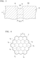
- FIG. 1 shows a cross-sectional microstructure of a wound iron core 20 stress-relief-annealed at 800°C for two hours in the manufacturing step of the transformer.
- This wound iron core 20 is formed of a grain-oriented electrical steel sheet 10 having a groove 12 formed on a surface 10A in the laser groove formation step.
- FIG. 1 shows a microstructural photograph of a cross section orthogonal to the groove 12 formed on the surface 10A in the grain-oriented electrical steel sheet 10 configuring the wound iron core 20.
- a subgrain boundary 14 is generated on a central side (arrow X side) in the thickness direction of the grain-oriented electrical steel sheet 10 with respect to the groove 12.
- the subgrain boundary refers to a low-angle grain boundary in which the orientation difference (crystal orientation difference) is 15° or less.
- FIG. 2 shows the analysis results of the crystal orientation differences on the central side in the thickness direction of the grain-oriented electrical steel sheet 10 with respect to the groove 12.
- a cross section perpendicular to a surface of the steel sheet including the rolling direction of the grain-oriented electrical steel sheet 10 shown in FIG. 1 was almost distortion-freely polished with colloidal silica or colloidal alumina, and the crystal orientation differences were analyzed by electron backscatter diffraction (EBSD) at a plurality of analysis points on an analysis position P.
- EBSD electron backscatter diffraction
- the horizontal axis of a graph shown in FIG. 2 indicates the measurement point numbers of the measurement points of crystal orientations arranged at equal intervals on the analysis position P in FIG. 1 from the left side.
- the vertical axis of the graph shown in FIG. 2 indicates crystal orientation differences (deg) at the respective analysis points.
- crystal orientation differences the integral values from a reference point (origin) at which the subgrain boundary 14 was not present were used.
- the measurement points at which these integral values were obtained were set to a depth position 5 ⁇ m away from the groove bottom in an X direction (a direction toward the central side in the thickness direction of the grain-oriented electrical steel sheet) with respect to the concave groove 12 shown in FIG. 1 .
- 29 places arranged at equal intervals (2 ⁇ m intervals) in a range corresponding to the groove width in a direction parallel to the surface of the steel sheet were used as the measurement points.
- a region having a different contrast from the circumference, which is considered as the subgrain boundary 14 is generated below the groove 12, and thus the first left measurement point of these measurement points is determined as the reference point at which the subgrain boundary 14 was not present.
- the crystal orientation differences reach 3 to 5 (deg). From this fact, it is found that the subgrain boundary 14 (refer to FIG. 1 ) is generated on the central side (arrow X side) in the thickness direction of the grain-oriented electrical steel sheet 10 with respect to the groove 12.
- FIG. 3 schematically shows the cross section of the grain-oriented electrical steel sheet 10 to be stress-relief-annealed.
- the groove 12 is formed by a laser process.
- the KAM value in a region on the central side (arrow X side) in the thickness direction of the grain-oriented electrical steel sheet 10 with respect to the groove 12 (hereinafter, referred to as the "groove peripheral region") 16 increases.
- FIG. 1 shows a cross section orthogonal to the groove 12 on the surface 10A of the grain-oriented electrical steel sheet 10. That is, FIG. 1 shows a cross section of the grain-oriented electrical steel sheet 10 cut along the width direction.
- the groove peripheral region 16 refers to, for example, in the cross section of the grain-oriented electrical steel sheet 10 shown in FIG. 3 , a region on the central side (arrow X side) in the thickness direction of the grain-oriented electrical steel sheet 10 with respect to the groove 12 and a region surrounded by a square having one side in contact with a groove bottom 12A of the groove 12 and having a length of 50 ⁇ m in each side.
- the groove bottom 12A of the groove 12 mentioned herein refers to the deepest portion of the groove 12. Furthermore, the fact that one side of the square is in contact with the groove bottom 12A of the groove 12 refers to a state in which one side of the square is in contact with the groove bottom 12A (the deepest portion) of the groove 12 in a state in which the side is placed parallel to the surface 10A of the grain-oriented electrical steel sheet 10.
- KAM Kernel Average Misorientation
- the KAM value can be obtained by using hexagonal pixels C as shown in FIG. 4 and mapping the groove peripheral region 16 shown in FIG. 3 .
- the average value of orientation differences between a specific pixel C A and six pixels C B adjacent to the specific pixel is computed, and this average value can be regarded as the KAM value of the predetermined pixel C A .
- the KAM value of the groove peripheral region 16 can also be determined by regulating a step size of, for example, approximately 0.1 to 1 ⁇ m in the groove peripheral region 16, setting a probe diameter to 10 nm or the like, computing the KAM values at a considerable number, for example, 10,000 places in the groove peripheral region 16, and adopting the absolute maximum value thereof.
- pixels being used are not limited to the hexagonal pixels C shown in FIG. 4 , and pixels with a different shape such as a square may also be used.
- a thread tensile force of 2 MPa or more and 15 MPa or less is imparted to the grain-oriented electrical steel sheet 10 in the laser groove formation step such that the KAM value in the groove peripheral region 16 of the grain-oriented electrical steel sheet 10 reaches 0.1 or more and 3.0 or less.
- the cooling rate of the grain-oriented electrical steel sheet 10 is adjusted to 20°C/s or more and 100°C/s or less in the flattening annealing step such that the KAM value in the groove peripheral region 16 of the grain-oriented electrical steel sheet 10 reaches 0.1 or more and 3.0 or less.
- the deterioration of the iron loss in the wound iron core (the grain-oriented electrical steel sheet 10) can be suppressed even when the wound iron core is stress-relief-annealed in the manufacturing step of the transformer.
- a KAM value in a groove peripheral region of a grain-oriented electrical steel sheet having grooves formed on a surface by a laser process was measured.
- a 25 KVA monolayer wound iron core was produced from the grain-oriented electrical steel sheet for which the KAM value was measured.
- the produced wound iron core was stress-relief-annealed, and the iron loss of a wound iron core (grain-oriented electrical steel sheet) was measured.
- a similar wound iron core was produced using a grain-oriented electrical steel sheet having no grooves formed on the surface, and the transformer iron loss was 36 W.
- the iron loss of the wound iron core made of this grain-oriented electrical steel sheet having no grooves formed thereon was regarded as a reference value and compared with the iron loss of the wound iron core made of the grain-oriented electrical steel sheet for which the KAM value was measured, thereby obtaining an iron loss improvement percentage (%) described below.
- the grain-oriented electrical steel sheets were manufactured using the same manufacturing method as the embodiment.
- the heating temperature (baking temperature) of the grain-oriented electrical steel was set to 800°C to 850°C
- the cooling rate of the grain-oriented electrical steel sheet was set to 20°C/s or more and 100°C/s or less.
- B8 refers to the density of magnetic flux [T] generated in the grain-oriented electrical steel sheet when the grain-oriented electrical steel sheet is magnetized in a rolling direction by a magnetizing force of 800 A/m.
- the processing conditions for the grooves (laser grooves) formed on the surface of the grain-oriented electrical steel sheet are as described below.
- FIG. 3 shows the cross section of the grain-oriented electrical steel sheet 10 having the groove 12 formed on the surface 10A by a laser process.
- the KAM value in the groove peripheral region 16 on the central side (arrow X side) in the thickness direction of the grain-oriented electrical steel sheet 10 with respect to the groove 12 was measured.
- the KAM value refers to an index indicating the degree of a relative difference between the orientations of adjacent crystal grains in a predetermined cross section of the grain-oriented electrical steel sheet.
- Kernel Average Misorientation KAM
- a strain-free cross section process was carried out by ion milling or the like in the cross section of the grain-oriented electrical steel sheet 10, and the crystal orientation differences were analyzed by the electron backscatter diffraction (EBSD) of a field emission-scanning electron microscope (FE-SEM).
- EBSD electron backscatter diffraction
- FE-SEM field emission-scanning electron microscope
- the average value of orientation differences between a predetermined pixel C A and six pixels C B adjacent to the pixel C A was computed, and this average value was regarded as the KAM value of the predetermined pixel C A .
- the absolute maximum value of the KAM values of the pixels C in the groove peripheral region 16 was regarded as the KAM value of the groove peripheral region 16.
- the step size S of the pixel C was, for example, 0.1 to 1 ⁇ m.
- the probe diameter was set to 10 nm.
- the step size was set to 0.5 ⁇ m. Therefore, for the groove peripheral region 16, the KAM values at 10,000 places were computed, and the absolute maximum value thereof was regarded as the KAM value of the groove peripheral region 16.
- the iron loss improvement percentage ⁇ of the wound iron core was computed from Expression (1) by obtaining an iron loss W0 of the wound iron core formed of the grain-oriented electrical steel sheet having no grooves formed thereon and an iron loss Wg of the wound iron core formed of the grain-oriented electrical steel sheet having grooves formed by a laser process.
- ⁇ W 0 ⁇ Wg / W 0 ⁇ 100
- the iron losses W0 and Wg of the wound iron cores were measured using an electric power meter after a primary winding (excitation winding) and a secondary winding (search coil) were wound around the wound iron cores respectively.
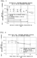
- a relationship among the KAM value of the groove peripheral region of the grain-oriented electrical steel sheet to be stress-relief-annealed, the iron loss improvement percentage ⁇ of the stress-relief-annealed wound iron core (grain-oriented electrical steel sheet), and the iron loss improvement percentage of a single sheet to be stress-relief-annealed (SST improvement percentage: an improvement percentage based on an iron loss value measured by a single sheet test (regulated in JIS C2556)) is shown in FIG. 5 .
- a plot indicated by a reference symbol D1 (0 as a sign) in FIG. 5 is about the iron loss improvement percentage ⁇ of the stress-relief-annealed wound iron core formed on the grain-oriented electrical steel sheet having grooves formed on the surface by a laser process.
- a plot indicated by a reference symbol D2 in FIG. 5 is about the iron loss improvement percentage ⁇ of the stress-relief-annealed wound iron core having grooves formed on the surface by an etching method described below.
- a plot indicated by a reference symbol D0 ( ⁇ as a sign) in FIG. 5 is about the iron loss improvement percentage of a single sheet to be stress-relief-annealed (SST improvement percentage).
- the iron loss improvement percentage ⁇ of the grain-oriented electrical steel sheet was computed from Expression (1) by respectively measuring the iron loss W0 of the grain-oriented electrical steel sheet having no grooves and the iron loss Wg of the grain-oriented electrical steel sheet having grooves formed by a laser process using a single sheet tester (SST) method which is a well-known iron loss measurement method. Therefore, in a case where the iron loss improvement percentage ⁇ of the wound iron core is lower than the iron loss improvement percentage of the single sheet to be stress-relief-annealed, it is confirmed that stress relief annealing deteriorates the iron loss.
- SST single sheet tester
- a stress-relief-annealed wound iron core formed of a grain-oriented electrical steel sheet having a KAM value of more than 3.0 in the groove peripheral region has an iron loss improvement percentage ⁇ lower than the iron loss improvement percentage of the single sheet, and thus it is possible to determine that the iron loss of the wound iron core deteriorated.
- the subgrain boundary 14 was generated on the central side (arrow X side) in the thickness direction of the grain-oriented electrical steel sheet 10 with respect to the groove 12.
- a stress-relief-annealed wound iron core formed of a grain-oriented electrical steel sheet having a KAM value of 0.1 or more and 3.0 or less in the groove peripheral region had an iron loss improvement percentage ⁇ that became equal to or higher than the iron loss improvement percentage of the single sheet, and thus the iron loss of the wound iron core was reduced.
- the cause of the deterioration of the iron loss of the stress-relief-annealed wound iron core is considered to be the subgrain boundary generated on the central side in the thickness direction of the grain-oriented electrical steel sheet with respect to the groove in the stress-relief-annealed wound iron core.
- the amount of this subgrain boundary generated has a correlation with the KAM value in the groove peripheral region of the grain-oriented electrical steel sheet to be stress-relief-annealed.
- the KAM value in the groove peripheral region of the grain-oriented electrical steel sheet to be stress-relief-annealed increases, in the stress-relief-annealed wound iron core, the amount of the subgrain boundary generated on the central side in the thickness direction of the grain-oriented electrical steel sheet with respect to the groove increases.
- the KAM value in the groove peripheral region of the grain-oriented electrical steel sheet to be stress-relief-annealed decreases, in the stress-relief-annealed wound iron core, the amount of the subgrain boundary generated on the central side in the thickness direction of the grain-oriented electrical steel sheet with respect to the groove decreases.
- the iron loss of a wound iron core deteriorates during the stress relief annealing of a transformer on the basis of the KAM value in the groove peripheral region of the grain-oriented electrical steel sheet to be stress-relief-annealed.
- the iron loss of a stress-relief-annealed wound iron core can be efficiently reduced by decreasing the KAM value in the groove peripheral region of the grain-oriented electrical steel sheet.
- the KAM value in the groove peripheral region is preferably as small as possible.
- the lower limit of the KAM value is set to 0.1.
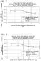
- FIG. 6 A graph showing the relationship between the thread tensile force of the grain-oriented electrical steel sheet in the laser groove formation step and the iron loss improvement percentage ⁇ of the stress-relief-annealed wound iron core is shown in FIG. 6 .
- the thread tensile force of the grain-oriented electrical steel sheet exceeded 15 MPa
- the iron loss improvement percentage ⁇ of the stress-relief-annealed wound iron core became lower than the iron loss improvement percentage of the single sheet (SST improvement percentage), and the iron loss of the wound iron core deteriorated.
- the thread tensile force of the grain-oriented electrical steel sheet is 9 MPa or less, the iron loss improvement percentage ⁇ of the wound iron core became higher than the iron loss improvement percentage of the single sheet (SST improvement percentage), and the iron loss of the wound iron core was reduced. Therefore, the thread tensile force of the grain-oriented electrical steel sheet is more preferably 9 MPa or less.
- the thread tensile force in the laser groove formation step is preferably 2 MPa or more. This is because, when the thread tensile force is less than 2 MPa, the grain-oriented electrical steel sheet is likely to vibrate while being transported, and a process defect of the laser process is likely to be caused.
- FIG. 7 a graph showing a relationship between the KAM value in the groove peripheral region of the grain-oriented electrical steel sheet to be stress-relief-annealed and the iron loss improvement percentage ⁇ of the stress-relief-annealed wound iron core is shown in FIG. 7 .
- the KAM value in the groove peripheral region is 3.0 or less, the iron loss improvement percentage ⁇ of the wound iron core became equal to or higher than the iron loss improvement percentage of the single sheet (SST improvement percentage), and, particularly, when the KAM value in the groove peripheral region was 2.0 or less, the iron loss improvement percentage ⁇ of the wound iron core became higher than the iron loss improvement percentage of the single sheet, and the iron loss was reduced. Therefore, the KAM value in the groove peripheral region is more preferably 2.0 or less.
- the cooling rate of the grain-oriented electrical steel sheet was changed as shown in Table 2, the KAM value in the groove peripheral region of the grain-oriented electrical steel sheet was measured, and the iron loss improvement percentage ⁇ of the stress-relief-annealed wound iron core was obtained [Table 2] Cooling rate (°C/sec) KAM value in groove peripheral region before stress relief annealing (deg) Iron loss improvement percentage of wound core after stress relief annealing (%) Iron loss improvement percentage of single sheet SST before stress relief annealing (%) 20 0.1 19.1 17.1 50 0.9 18.9 16.6 70 1.9 18.3 16.8 100 3 15.0 15.0 120 3.3 14.5 15.0 150 3.7 12.9 14.8
- FIG. 8 A graph showing the relationship between the cooling rate of the grain-oriented electrical steel sheet in the insulating coating re-formation step carried out after the formation of the laser grooves and the iron loss improvement percentage ⁇ of the stress-relief-annealed wound iron core is shown in FIG. 8 .
- the cooling rate of the grain-oriented electrical steel sheet was in a range of 20°C/s to 100°C/s
- the iron loss improvement percentage ⁇ of the wound iron core became equal to or higher than the iron loss improvement percentage of the single sheet (SST improvement percentage).
- the cooling rate exceeded 100°C/s the iron loss improvement percentage ⁇ of the wound iron core became lower than the iron loss improvement percentage of the single sheet, and the iron loss of the wound iron core deteriorated.
- the cooling rate of the grain-oriented electrical steel sheet is 75°C/s or less, the iron loss improvement percentage ⁇ of the wound iron core more reliably became higher than the iron loss improvement percentage of the single sheet, and the iron loss of the wound iron core was reduced. Therefore, the cooling rate of the grain-oriented electrical steel sheet is more preferably 75°C/s or less.
- the cooling rate of the grain-oriented electrical steel sheet in the insulating coating re-formation step carried out after the formation of the laser grooves is preferably 20°C/s or more. This is because, when the cooling rate became less than 20°C/s, the manufacturability (cooling efficiency) of the grain-oriented electrical steel sheet degrades.
- FIG. 9 a graph showing the relationship between the KAM value in the groove peripheral region of the grain-oriented electrical steel sheet to be stress-relief-annealed and the iron loss improvement percentage ⁇ of the stress-relief-annealed wound iron core is shown in FIG. 9 .
- the KAM value in the groove peripheral region was 3.0 or less
- the iron loss improvement percentage ⁇ of the wound iron core became higher than the iron loss improvement percentage of the single sheet (SST improvement percentage) and the iron loss was reduced.
- a measurement method of the KAM value in the groove peripheral region of the grain-oriented electrical steel sheet can be appropriately changed.
- the size of the pixel C (refer to FIG. 4 ) and the like at the time of mapping the groove peripheral region can be appropriately changed.
- the insulating coating agent application step and the flattening annealing step were carried out between the final annealing step and the laser groove formation step.
- the insulating coating agent application step and the flattening annealing step may be carried out after the laser groove formation step. That is, the final annealing step, the laser groove formation step, the heat treatment step, the insulating coating agent application step, and the flattening annealing step may also be carried out in this order. In this case, the insulating coating re-formation step becomes unnecessary, and thus the number of the manufacturing steps of the grain-oriented electrical steel sheet is reduced.
Landscapes
- Chemical & Material Sciences (AREA)
- Engineering & Computer Science (AREA)
- Physics & Mathematics (AREA)
- Mechanical Engineering (AREA)
- Metallurgy (AREA)
- Organic Chemistry (AREA)
- Materials Engineering (AREA)
- Crystallography & Structural Chemistry (AREA)
- Thermal Sciences (AREA)
- Electromagnetism (AREA)
- Manufacturing & Machinery (AREA)
- Optics & Photonics (AREA)
- Dispersion Chemistry (AREA)
- Power Engineering (AREA)
- Plasma & Fusion (AREA)
- Manufacturing Of Steel Electrode Plates (AREA)
- Soft Magnetic Materials (AREA)
Applications Claiming Priority (2)
| Application Number | Priority Date | Filing Date | Title |
|---|---|---|---|
| JP2018032552 | 2018-02-26 | ||
| PCT/JP2019/007251 WO2019164012A1 (ja) | 2018-02-26 | 2019-02-26 | 方向性電磁鋼板 |
Publications (3)
| Publication Number | Publication Date |
|---|---|
| EP3760746A1 EP3760746A1 (en) | 2021-01-06 |
| EP3760746A4 EP3760746A4 (en) | 2021-10-20 |
| EP3760746B1 true EP3760746B1 (en) | 2024-02-14 |
Family
ID=67687151
Family Applications (1)
| Application Number | Title | Priority Date | Filing Date |
|---|---|---|---|
| EP19758237.2A Active EP3760746B1 (en) | 2018-02-26 | 2019-02-26 | Grain-oriented electrical steel sheet |
Country Status (8)
| Country | Link |
|---|---|
| US (1) | US11393612B2 (pl) |
| EP (1) | EP3760746B1 (pl) |
| JP (1) | JP6614398B1 (pl) |
| KR (1) | KR102478773B1 (pl) |
| CN (1) | CN111742068B (pl) |
| PL (1) | PL3760746T3 (pl) |
| RU (1) | RU2765033C1 (pl) |
| WO (1) | WO2019164012A1 (pl) |
Families Citing this family (4)
| Publication number | Priority date | Publication date | Assignee | Title |
|---|---|---|---|---|
| KR102428854B1 (ko) * | 2019-12-20 | 2022-08-02 | 주식회사 포스코 | 방향성 전기강판 및 그 자구미세화 방법 |
| JP7485954B2 (ja) * | 2020-10-26 | 2024-05-17 | 日本製鉄株式会社 | 巻鉄心 |
| EP4527950A4 (en) * | 2022-06-20 | 2025-11-26 | Jfe Steel Corp | METHOD FOR PRODUCING ELECTROMAGNETIC STEEL SHEET AND COLD-ROLL-ROLL SHEET |
| JPWO2025183132A1 (pl) * | 2024-03-01 | 2025-09-04 |
Family Cites Families (17)
| Publication number | Priority date | Publication date | Assignee | Title |
|---|---|---|---|---|
| JPS5234222B2 (pl) | 1972-02-04 | 1977-09-02 | ||
| SU1096291A1 (ru) * | 1983-01-10 | 1984-06-07 | Научно-исследовательский институт металлургии | Способ изготовлени анизотропной холоднокатаной электротехнической стали |
| SU1647030A1 (ru) * | 1988-07-22 | 1991-05-07 | Институт физики металлов Уральского отделения АН СССР | Способ производства полосы анизотропной электротехнической стали |
| JP5234222B2 (ja) | 2010-04-01 | 2013-07-10 | 新日鐵住金株式会社 | 方向性電磁鋼板及びその製造方法 |
| JP5853352B2 (ja) | 2010-08-06 | 2016-02-09 | Jfeスチール株式会社 | 方向性電磁鋼板およびその製造方法 |
| BR112013005450B1 (pt) * | 2010-09-10 | 2019-05-07 | Jfe Steel Corporation | Chapa de aço elétrico com grão orientado e método para produção da mesma. |
| US10131018B2 (en) | 2012-04-27 | 2018-11-20 | Nippon Steel & Sumitomo Metal Corporation | Grain-oriented magnetic steel sheet and method of producing the same |
| JP5871137B2 (ja) * | 2012-12-12 | 2016-03-01 | Jfeスチール株式会社 | 方向性電磁鋼板 |
| SE542101C2 (en) * | 2014-04-02 | 2020-02-25 | Jfe Steel Corp | Iron powder for iron powder cores and method for selecting iron powder for iron powder cores |
| WO2016105055A1 (ko) | 2014-12-24 | 2016-06-30 | 주식회사 포스코 | 방향성 전기강판 및 그 제조방법 |
| KR101719231B1 (ko) | 2014-12-24 | 2017-04-04 | 주식회사 포스코 | 방향성 전기강판 및 그 제조방법 |
| BR112017019141B1 (pt) * | 2015-04-20 | 2021-09-08 | Nippon Steel Corporation | Chapa de aço elétrico com grão orientado |
| EP3287537B1 (en) * | 2015-04-20 | 2020-01-29 | Nippon Steel Corporation | Oriented electromagnetic steel sheet |
| KR102010166B1 (ko) * | 2015-04-20 | 2019-08-12 | 닛폰세이테츠 가부시키가이샤 | 방향성 전자기 강판 |
| MX2018001081A (es) | 2015-07-28 | 2018-05-07 | Jfe Steel Corp | Metodo de formacion de ranuras lineales y dispositivo de formacion de ranuras lineales. |
| KR102148383B1 (ko) * | 2016-01-22 | 2020-08-26 | 주식회사 포스코 | 방향성 전기강판의 자구미세화 방법과 그 장치 |
| JP2018032552A (ja) | 2016-08-25 | 2018-03-01 | トヨタ自動車株式会社 | リチウムイオン二次電池 |
-
2019
- 2019-02-26 KR KR1020207026301A patent/KR102478773B1/ko active Active
- 2019-02-26 JP JP2019526341A patent/JP6614398B1/ja active Active
- 2019-02-26 US US16/971,617 patent/US11393612B2/en active Active
- 2019-02-26 CN CN201980014946.4A patent/CN111742068B/zh active Active
- 2019-02-26 WO PCT/JP2019/007251 patent/WO2019164012A1/ja not_active Ceased
- 2019-02-26 RU RU2020129393A patent/RU2765033C1/ru active
- 2019-02-26 EP EP19758237.2A patent/EP3760746B1/en active Active
- 2019-02-26 PL PL19758237.2T patent/PL3760746T3/pl unknown
Also Published As
| Publication number | Publication date |
|---|---|
| CN111742068B (zh) | 2022-05-13 |
| RU2765033C1 (ru) | 2022-01-24 |
| KR102478773B1 (ko) | 2022-12-20 |
| KR20200118202A (ko) | 2020-10-14 |
| WO2019164012A1 (ja) | 2019-08-29 |
| CN111742068A (zh) | 2020-10-02 |
| EP3760746A1 (en) | 2021-01-06 |
| JP6614398B1 (ja) | 2019-12-04 |
| BR112020017171A2 (pt) | 2020-12-22 |
| EP3760746A4 (en) | 2021-10-20 |
| US11393612B2 (en) | 2022-07-19 |
| PL3760746T3 (pl) | 2024-05-20 |
| JPWO2019164012A1 (ja) | 2020-02-27 |
| US20200381150A1 (en) | 2020-12-03 |
Similar Documents
| Publication | Publication Date | Title |
|---|---|---|
| EP2599883B1 (en) | Orientated electromagnetic steel sheet and manufacturing method for same | |
| CN103069033B (zh) | 方向性电磁钢板及其制造方法 | |
| EP3287533B1 (en) | Oriented magnetic steel plate | |
| CN103080352B (zh) | 方向性电磁钢板 | |
| EP3913076B1 (en) | Grain-oriented electrical steel sheet and method for manufacturing the same | |
| US11393612B2 (en) | Grain-oriented electrical steel sheet | |
| EP3770282B1 (en) | Method for manufacturing grain-oriented electrical steel sheet and grain-oriented electrical steel sheet | |
| EP4123038A1 (en) | Grain-oriented electromagnetic steel sheet, and method for manufacturing grain-oriented electromagnetic steel sheet | |
| JP7031364B2 (ja) | 方向性電磁鋼板の製造方法 | |
| EP3913080A1 (en) | Grain-oriented electrical steel sheet and method for manufacturing same | |
| EP3748020B1 (en) | Grain-oriented electrical steel sheet | |
| US11450460B2 (en) | Grain-oriented electrical steel sheet | |
| TWI834443B (zh) | 晶粒取向性電氣片材及用於細化其中之磁域的方法 | |
| EP3913088B1 (en) | Method for manufacturing grain-oriented electrical steel sheet | |
| RU2858634C2 (ru) | Ленточный сердечник | |
| EP4625452A1 (en) | Wound core | |
| RU2776382C1 (ru) | Лист анизотропной электротехнической стали и способ его производства | |
| TWI887859B (zh) | 捲鐵心 | |
| EP4624617A1 (en) | Grain-oriented electrical steel sheet | |
| BR112020017171B1 (pt) | Chapa de aço elétrico de grão orientado | |
| CN120457230A (zh) | 方向性电磁钢板 |
Legal Events
| Date | Code | Title | Description |
|---|---|---|---|
| STAA | Information on the status of an ep patent application or granted ep patent |
Free format text: STATUS: THE INTERNATIONAL PUBLICATION HAS BEEN MADE |
|
| PUAI | Public reference made under article 153(3) epc to a published international application that has entered the european phase |
Free format text: ORIGINAL CODE: 0009012 |
|
| STAA | Information on the status of an ep patent application or granted ep patent |
Free format text: STATUS: REQUEST FOR EXAMINATION WAS MADE |
|
| 17P | Request for examination filed |
Effective date: 20200921 |
|
| AK | Designated contracting states |
Kind code of ref document: A1 Designated state(s): AL AT BE BG CH CY CZ DE DK EE ES FI FR GB GR HR HU IE IS IT LI LT LU LV MC MK MT NL NO PL PT RO RS SE SI SK SM TR |
|
| AX | Request for extension of the european patent |
Extension state: BA ME |
|
| DAV | Request for validation of the european patent (deleted) | ||
| DAX | Request for extension of the european patent (deleted) | ||
| A4 | Supplementary search report drawn up and despatched |
Effective date: 20210922 |
|
| RIC1 | Information provided on ipc code assigned before grant |
Ipc: C21D 3/04 20060101ALN20210916BHEP Ipc: C21D 9/46 20060101ALN20210916BHEP Ipc: C21D 6/00 20060101ALN20210916BHEP Ipc: C21D 8/00 20060101ALN20210916BHEP Ipc: H01F 1/16 20060101ALI20210916BHEP Ipc: C21D 10/00 20060101ALI20210916BHEP Ipc: C22C 38/06 20060101ALI20210916BHEP Ipc: H01F 1/147 20060101ALI20210916BHEP Ipc: C22C 38/00 20060101ALI20210916BHEP Ipc: C21D 8/12 20060101AFI20210916BHEP |
|
| RIC1 | Information provided on ipc code assigned before grant |
Ipc: C21D 3/04 20060101ALN20220718BHEP Ipc: C21D 9/46 20060101ALN20220718BHEP Ipc: C21D 6/00 20060101ALN20220718BHEP Ipc: C21D 8/00 20060101ALN20220718BHEP Ipc: C22C 38/02 20060101ALI20220718BHEP Ipc: H01F 1/16 20060101ALI20220718BHEP Ipc: C21D 10/00 20060101ALI20220718BHEP Ipc: C22C 38/06 20060101ALI20220718BHEP Ipc: H01F 1/147 20060101ALI20220718BHEP Ipc: C22C 38/00 20060101ALI20220718BHEP Ipc: C21D 8/12 20060101AFI20220718BHEP |
|
| GRAP | Despatch of communication of intention to grant a patent |
Free format text: ORIGINAL CODE: EPIDOSNIGR1 |
|
| STAA | Information on the status of an ep patent application or granted ep patent |
Free format text: STATUS: GRANT OF PATENT IS INTENDED |
|
| RIC1 | Information provided on ipc code assigned before grant |
Ipc: C21D 3/04 20060101ALN20220726BHEP Ipc: C21D 9/46 20060101ALN20220726BHEP Ipc: C21D 6/00 20060101ALN20220726BHEP Ipc: C21D 8/00 20060101ALN20220726BHEP Ipc: C22C 38/02 20060101ALI20220726BHEP Ipc: H01F 1/16 20060101ALI20220726BHEP Ipc: C21D 10/00 20060101ALI20220726BHEP Ipc: C22C 38/06 20060101ALI20220726BHEP Ipc: H01F 1/147 20060101ALI20220726BHEP Ipc: C22C 38/00 20060101ALI20220726BHEP Ipc: C21D 8/12 20060101AFI20220726BHEP |
|
| RIC1 | Information provided on ipc code assigned before grant |
Ipc: C21D 3/04 20060101ALN20220818BHEP Ipc: C21D 9/46 20060101ALN20220818BHEP Ipc: C21D 6/00 20060101ALN20220818BHEP Ipc: C21D 8/00 20060101ALN20220818BHEP Ipc: C22C 38/02 20060101ALI20220818BHEP Ipc: H01F 1/16 20060101ALI20220818BHEP Ipc: C21D 10/00 20060101ALI20220818BHEP Ipc: C22C 38/06 20060101ALI20220818BHEP Ipc: H01F 1/147 20060101ALI20220818BHEP Ipc: C22C 38/00 20060101ALI20220818BHEP Ipc: C21D 8/12 20060101AFI20220818BHEP |
|
| INTG | Intention to grant announced |
Effective date: 20220831 |
|
| GRAJ | Information related to disapproval of communication of intention to grant by the applicant or resumption of examination proceedings by the epo deleted |
Free format text: ORIGINAL CODE: EPIDOSDIGR1 |
|
| STAA | Information on the status of an ep patent application or granted ep patent |
Free format text: STATUS: REQUEST FOR EXAMINATION WAS MADE |
|
| STAA | Information on the status of an ep patent application or granted ep patent |
Free format text: STATUS: EXAMINATION IS IN PROGRESS |
|
| INTC | Intention to grant announced (deleted) | ||
| 17Q | First examination report despatched |
Effective date: 20230209 |
|
| RIN1 | Information on inventor provided before grant (corrected) |
Inventor name: OKUMURA, SHUNSUKE Inventor name: KATAOKA, TAKASHI Inventor name: ARAI, SATOSHI Inventor name: HAMAMURA, HIDEYUKI |
|
| GRAP | Despatch of communication of intention to grant a patent |
Free format text: ORIGINAL CODE: EPIDOSNIGR1 |
|
| STAA | Information on the status of an ep patent application or granted ep patent |
Free format text: STATUS: GRANT OF PATENT IS INTENDED |
|
| RIC1 | Information provided on ipc code assigned before grant |
Ipc: C21D 3/04 20060101ALN20230909BHEP Ipc: C21D 9/46 20060101ALN20230909BHEP Ipc: C21D 6/00 20060101ALN20230909BHEP Ipc: C21D 8/00 20060101ALN20230909BHEP Ipc: C22C 38/02 20060101ALI20230909BHEP Ipc: H01F 1/16 20060101ALI20230909BHEP Ipc: C21D 10/00 20060101ALI20230909BHEP Ipc: C22C 38/06 20060101ALI20230909BHEP Ipc: H01F 1/147 20060101ALI20230909BHEP Ipc: C22C 38/00 20060101ALI20230909BHEP Ipc: C21D 8/12 20060101AFI20230909BHEP |
|
| INTG | Intention to grant announced |
Effective date: 20231004 |
|
| GRAS | Grant fee paid |
Free format text: ORIGINAL CODE: EPIDOSNIGR3 |
|
| GRAA | (expected) grant |
Free format text: ORIGINAL CODE: 0009210 |
|
| STAA | Information on the status of an ep patent application or granted ep patent |
Free format text: STATUS: THE PATENT HAS BEEN GRANTED |
|
| AK | Designated contracting states |
Kind code of ref document: B1 Designated state(s): AL AT BE BG CH CY CZ DE DK EE ES FI FR GB GR HR HU IE IS IT LI LT LU LV MC MK MT NL NO PL PT RO RS SE SI SK SM TR |
|
| REG | Reference to a national code |
Ref country code: GB Ref legal event code: FG4D |
|
| REG | Reference to a national code |
Ref country code: CH Ref legal event code: EP |
|
| REG | Reference to a national code |
Ref country code: DE Ref legal event code: R096 Ref document number: 602019046523 Country of ref document: DE |
|
| REG | Reference to a national code |
Ref country code: IE Ref legal event code: FG4D |
|
| REG | Reference to a national code |
Ref country code: LT Ref legal event code: MG9D |
|
| REG | Reference to a national code |
Ref country code: NL Ref legal event code: MP Effective date: 20240214 |
|
| PG25 | Lapsed in a contracting state [announced via postgrant information from national office to epo] |
Ref country code: IS Free format text: LAPSE BECAUSE OF FAILURE TO SUBMIT A TRANSLATION OF THE DESCRIPTION OR TO PAY THE FEE WITHIN THE PRESCRIBED TIME-LIMIT Effective date: 20240614 |
|
| PG25 | Lapsed in a contracting state [announced via postgrant information from national office to epo] |
Ref country code: LT Free format text: LAPSE BECAUSE OF FAILURE TO SUBMIT A TRANSLATION OF THE DESCRIPTION OR TO PAY THE FEE WITHIN THE PRESCRIBED TIME-LIMIT Effective date: 20240214 |
|
| PG25 | Lapsed in a contracting state [announced via postgrant information from national office to epo] |
Ref country code: GR Free format text: LAPSE BECAUSE OF FAILURE TO SUBMIT A TRANSLATION OF THE DESCRIPTION OR TO PAY THE FEE WITHIN THE PRESCRIBED TIME-LIMIT Effective date: 20240515 |
|
| REG | Reference to a national code |
Ref country code: AT Ref legal event code: MK05 Ref document number: 1657063 Country of ref document: AT Kind code of ref document: T Effective date: 20240214 |
|
| PG25 | Lapsed in a contracting state [announced via postgrant information from national office to epo] |
Ref country code: NL Free format text: LAPSE BECAUSE OF FAILURE TO SUBMIT A TRANSLATION OF THE DESCRIPTION OR TO PAY THE FEE WITHIN THE PRESCRIBED TIME-LIMIT Effective date: 20240214 Ref country code: HR Free format text: LAPSE BECAUSE OF FAILURE TO SUBMIT A TRANSLATION OF THE DESCRIPTION OR TO PAY THE FEE WITHIN THE PRESCRIBED TIME-LIMIT Effective date: 20240214 Ref country code: RS Free format text: LAPSE BECAUSE OF FAILURE TO SUBMIT A TRANSLATION OF THE DESCRIPTION OR TO PAY THE FEE WITHIN THE PRESCRIBED TIME-LIMIT Effective date: 20240514 |
|
| PG25 | Lapsed in a contracting state [announced via postgrant information from national office to epo] |
Ref country code: ES Free format text: LAPSE BECAUSE OF FAILURE TO SUBMIT A TRANSLATION OF THE DESCRIPTION OR TO PAY THE FEE WITHIN THE PRESCRIBED TIME-LIMIT Effective date: 20240214 |
|
| PG25 | Lapsed in a contracting state [announced via postgrant information from national office to epo] |
Ref country code: AT Free format text: LAPSE BECAUSE OF FAILURE TO SUBMIT A TRANSLATION OF THE DESCRIPTION OR TO PAY THE FEE WITHIN THE PRESCRIBED TIME-LIMIT Effective date: 20240214 |
|
| PG25 | Lapsed in a contracting state [announced via postgrant information from national office to epo] |
Ref country code: RS Free format text: LAPSE BECAUSE OF FAILURE TO SUBMIT A TRANSLATION OF THE DESCRIPTION OR TO PAY THE FEE WITHIN THE PRESCRIBED TIME-LIMIT Effective date: 20240514 Ref country code: NO Free format text: LAPSE BECAUSE OF FAILURE TO SUBMIT A TRANSLATION OF THE DESCRIPTION OR TO PAY THE FEE WITHIN THE PRESCRIBED TIME-LIMIT Effective date: 20240514 Ref country code: NL Free format text: LAPSE BECAUSE OF FAILURE TO SUBMIT A TRANSLATION OF THE DESCRIPTION OR TO PAY THE FEE WITHIN THE PRESCRIBED TIME-LIMIT Effective date: 20240214 Ref country code: LT Free format text: LAPSE BECAUSE OF FAILURE TO SUBMIT A TRANSLATION OF THE DESCRIPTION OR TO PAY THE FEE WITHIN THE PRESCRIBED TIME-LIMIT Effective date: 20240214 Ref country code: IS Free format text: LAPSE BECAUSE OF FAILURE TO SUBMIT A TRANSLATION OF THE DESCRIPTION OR TO PAY THE FEE WITHIN THE PRESCRIBED TIME-LIMIT Effective date: 20240614 Ref country code: HR Free format text: LAPSE BECAUSE OF FAILURE TO SUBMIT A TRANSLATION OF THE DESCRIPTION OR TO PAY THE FEE WITHIN THE PRESCRIBED TIME-LIMIT Effective date: 20240214 Ref country code: GR Free format text: LAPSE BECAUSE OF FAILURE TO SUBMIT A TRANSLATION OF THE DESCRIPTION OR TO PAY THE FEE WITHIN THE PRESCRIBED TIME-LIMIT Effective date: 20240515 Ref country code: FI Free format text: LAPSE BECAUSE OF FAILURE TO SUBMIT A TRANSLATION OF THE DESCRIPTION OR TO PAY THE FEE WITHIN THE PRESCRIBED TIME-LIMIT Effective date: 20240214 Ref country code: ES Free format text: LAPSE BECAUSE OF FAILURE TO SUBMIT A TRANSLATION OF THE DESCRIPTION OR TO PAY THE FEE WITHIN THE PRESCRIBED TIME-LIMIT Effective date: 20240214 Ref country code: BG Free format text: LAPSE BECAUSE OF FAILURE TO SUBMIT A TRANSLATION OF THE DESCRIPTION OR TO PAY THE FEE WITHIN THE PRESCRIBED TIME-LIMIT Effective date: 20240214 Ref country code: AT Free format text: LAPSE BECAUSE OF FAILURE TO SUBMIT A TRANSLATION OF THE DESCRIPTION OR TO PAY THE FEE WITHIN THE PRESCRIBED TIME-LIMIT Effective date: 20240214 |
|
| PG25 | Lapsed in a contracting state [announced via postgrant information from national office to epo] |
Ref country code: PT Free format text: LAPSE BECAUSE OF FAILURE TO SUBMIT A TRANSLATION OF THE DESCRIPTION OR TO PAY THE FEE WITHIN THE PRESCRIBED TIME-LIMIT Effective date: 20240614 |
|
| PG25 | Lapsed in a contracting state [announced via postgrant information from national office to epo] |
Ref country code: SE Free format text: LAPSE BECAUSE OF FAILURE TO SUBMIT A TRANSLATION OF THE DESCRIPTION OR TO PAY THE FEE WITHIN THE PRESCRIBED TIME-LIMIT Effective date: 20240214 Ref country code: PT Free format text: LAPSE BECAUSE OF FAILURE TO SUBMIT A TRANSLATION OF THE DESCRIPTION OR TO PAY THE FEE WITHIN THE PRESCRIBED TIME-LIMIT Effective date: 20240614 Ref country code: LV Free format text: LAPSE BECAUSE OF FAILURE TO SUBMIT A TRANSLATION OF THE DESCRIPTION OR TO PAY THE FEE WITHIN THE PRESCRIBED TIME-LIMIT Effective date: 20240214 |
|
| REG | Reference to a national code |
Ref country code: CH Ref legal event code: PL |
|
| PG25 | Lapsed in a contracting state [announced via postgrant information from national office to epo] |
Ref country code: DK Free format text: LAPSE BECAUSE OF FAILURE TO SUBMIT A TRANSLATION OF THE DESCRIPTION OR TO PAY THE FEE WITHIN THE PRESCRIBED TIME-LIMIT Effective date: 20240214 |
|
| PG25 | Lapsed in a contracting state [announced via postgrant information from national office to epo] |
Ref country code: SM Free format text: LAPSE BECAUSE OF FAILURE TO SUBMIT A TRANSLATION OF THE DESCRIPTION OR TO PAY THE FEE WITHIN THE PRESCRIBED TIME-LIMIT Effective date: 20240214 |
|
| PG25 | Lapsed in a contracting state [announced via postgrant information from national office to epo] |
Ref country code: LU Free format text: LAPSE BECAUSE OF NON-PAYMENT OF DUE FEES Effective date: 20240226 |
|
| PG25 | Lapsed in a contracting state [announced via postgrant information from national office to epo] |
Ref country code: CH Free format text: LAPSE BECAUSE OF NON-PAYMENT OF DUE FEES Effective date: 20240229 |
|
| PG25 | Lapsed in a contracting state [announced via postgrant information from national office to epo] |
Ref country code: EE Free format text: LAPSE BECAUSE OF FAILURE TO SUBMIT A TRANSLATION OF THE DESCRIPTION OR TO PAY THE FEE WITHIN THE PRESCRIBED TIME-LIMIT Effective date: 20240214 |
|
| PG25 | Lapsed in a contracting state [announced via postgrant information from national office to epo] |
Ref country code: SK Free format text: LAPSE BECAUSE OF FAILURE TO SUBMIT A TRANSLATION OF THE DESCRIPTION OR TO PAY THE FEE WITHIN THE PRESCRIBED TIME-LIMIT Effective date: 20240214 |
|
| PG25 | Lapsed in a contracting state [announced via postgrant information from national office to epo] |
Ref country code: SM Free format text: LAPSE BECAUSE OF FAILURE TO SUBMIT A TRANSLATION OF THE DESCRIPTION OR TO PAY THE FEE WITHIN THE PRESCRIBED TIME-LIMIT Effective date: 20240214 Ref country code: SK Free format text: LAPSE BECAUSE OF FAILURE TO SUBMIT A TRANSLATION OF THE DESCRIPTION OR TO PAY THE FEE WITHIN THE PRESCRIBED TIME-LIMIT Effective date: 20240214 Ref country code: RO Free format text: LAPSE BECAUSE OF FAILURE TO SUBMIT A TRANSLATION OF THE DESCRIPTION OR TO PAY THE FEE WITHIN THE PRESCRIBED TIME-LIMIT Effective date: 20240214 Ref country code: LU Free format text: LAPSE BECAUSE OF NON-PAYMENT OF DUE FEES Effective date: 20240226 Ref country code: EE Free format text: LAPSE BECAUSE OF FAILURE TO SUBMIT A TRANSLATION OF THE DESCRIPTION OR TO PAY THE FEE WITHIN THE PRESCRIBED TIME-LIMIT Effective date: 20240214 Ref country code: DK Free format text: LAPSE BECAUSE OF FAILURE TO SUBMIT A TRANSLATION OF THE DESCRIPTION OR TO PAY THE FEE WITHIN THE PRESCRIBED TIME-LIMIT Effective date: 20240214 Ref country code: CH Free format text: LAPSE BECAUSE OF NON-PAYMENT OF DUE FEES Effective date: 20240229 |
|
| REG | Reference to a national code |
Ref country code: DE Ref legal event code: R097 Ref document number: 602019046523 Country of ref document: DE |
|
| PG25 | Lapsed in a contracting state [announced via postgrant information from national office to epo] |
Ref country code: MC Free format text: LAPSE BECAUSE OF FAILURE TO SUBMIT A TRANSLATION OF THE DESCRIPTION OR TO PAY THE FEE WITHIN THE PRESCRIBED TIME-LIMIT Effective date: 20240214 |
|
| PG25 | Lapsed in a contracting state [announced via postgrant information from national office to epo] |
Ref country code: MC Free format text: LAPSE BECAUSE OF FAILURE TO SUBMIT A TRANSLATION OF THE DESCRIPTION OR TO PAY THE FEE WITHIN THE PRESCRIBED TIME-LIMIT Effective date: 20240214 |
|
| PG25 | Lapsed in a contracting state [announced via postgrant information from national office to epo] |
Ref country code: IT Free format text: LAPSE BECAUSE OF FAILURE TO SUBMIT A TRANSLATION OF THE DESCRIPTION OR TO PAY THE FEE WITHIN THE PRESCRIBED TIME-LIMIT Effective date: 20240214 |
|
| REG | Reference to a national code |
Ref country code: BE Ref legal event code: MM Effective date: 20240229 |
|
| PLBE | No opposition filed within time limit |
Free format text: ORIGINAL CODE: 0009261 |
|
| STAA | Information on the status of an ep patent application or granted ep patent |
Free format text: STATUS: NO OPPOSITION FILED WITHIN TIME LIMIT |
|
| PG25 | Lapsed in a contracting state [announced via postgrant information from national office to epo] |
Ref country code: IT Free format text: LAPSE BECAUSE OF FAILURE TO SUBMIT A TRANSLATION OF THE DESCRIPTION OR TO PAY THE FEE WITHIN THE PRESCRIBED TIME-LIMIT Effective date: 20240214 |
|
| PG25 | Lapsed in a contracting state [announced via postgrant information from national office to epo] |
Ref country code: BE Free format text: LAPSE BECAUSE OF NON-PAYMENT OF DUE FEES Effective date: 20240229 |
|
| 26N | No opposition filed |
Effective date: 20241115 |
|
| PG25 | Lapsed in a contracting state [announced via postgrant information from national office to epo] |
Ref country code: IE Free format text: LAPSE BECAUSE OF NON-PAYMENT OF DUE FEES Effective date: 20240226 |
|
| PG25 | Lapsed in a contracting state [announced via postgrant information from national office to epo] |
Ref country code: IE Free format text: LAPSE BECAUSE OF NON-PAYMENT OF DUE FEES Effective date: 20240226 Ref country code: BE Free format text: LAPSE BECAUSE OF NON-PAYMENT OF DUE FEES Effective date: 20240229 |
|
| PG25 | Lapsed in a contracting state [announced via postgrant information from national office to epo] |
Ref country code: SI Free format text: LAPSE BECAUSE OF FAILURE TO SUBMIT A TRANSLATION OF THE DESCRIPTION OR TO PAY THE FEE WITHIN THE PRESCRIBED TIME-LIMIT Effective date: 20240214 |
|
| PGFP | Annual fee paid to national office [announced via postgrant information from national office to epo] |
Ref country code: GB Payment date: 20250102 Year of fee payment: 7 |
|
| PG25 | Lapsed in a contracting state [announced via postgrant information from national office to epo] |
Ref country code: CY Free format text: LAPSE BECAUSE OF FAILURE TO SUBMIT A TRANSLATION OF THE DESCRIPTION OR TO PAY THE FEE WITHIN THE PRESCRIBED TIME-LIMIT; INVALID AB INITIO Effective date: 20190226 |
|
| PG25 | Lapsed in a contracting state [announced via postgrant information from national office to epo] |
Ref country code: HU Free format text: LAPSE BECAUSE OF FAILURE TO SUBMIT A TRANSLATION OF THE DESCRIPTION OR TO PAY THE FEE WITHIN THE PRESCRIBED TIME-LIMIT; INVALID AB INITIO Effective date: 20190226 |
|
| PG25 | Lapsed in a contracting state [announced via postgrant information from national office to epo] |
Ref country code: TR Free format text: LAPSE BECAUSE OF FAILURE TO SUBMIT A TRANSLATION OF THE DESCRIPTION OR TO PAY THE FEE WITHIN THE PRESCRIBED TIME-LIMIT Effective date: 20240214 |
|
| PGFP | Annual fee paid to national office [announced via postgrant information from national office to epo] |
Ref country code: FR Payment date: 20251231 Year of fee payment: 8 |
|
| PGFP | Annual fee paid to national office [announced via postgrant information from national office to epo] |
Ref country code: PL Payment date: 20251230 Year of fee payment: 8 |
|
| PGFP | Annual fee paid to national office [announced via postgrant information from national office to epo] |
Ref country code: DE Payment date: 20260102 Year of fee payment: 8 |
|
| PGFP | Annual fee paid to national office [announced via postgrant information from national office to epo] |
Ref country code: CZ Payment date: 20260218 Year of fee payment: 8 |