EP3760554B1 - Vorrichtung zum automatischen öffnen eines mit einem versiegelungselement versehenen behälters - Google Patents
Vorrichtung zum automatischen öffnen eines mit einem versiegelungselement versehenen behälters Download PDFInfo
- Publication number
- EP3760554B1 EP3760554B1 EP19760835.9A EP19760835A EP3760554B1 EP 3760554 B1 EP3760554 B1 EP 3760554B1 EP 19760835 A EP19760835 A EP 19760835A EP 3760554 B1 EP3760554 B1 EP 3760554B1
- Authority
- EP
- European Patent Office
- Prior art keywords
- screw thread
- automatic opening
- spout
- locking
- containers
- Prior art date
- Legal status (The legal status is an assumption and is not a legal conclusion. Google has not performed a legal analysis and makes no representation as to the accuracy of the status listed.)
- Active
Links
Images


Classifications
-
- B—PERFORMING OPERATIONS; TRANSPORTING
- B65—CONVEYING; PACKING; STORING; HANDLING THIN OR FILAMENTARY MATERIAL
- B65D—CONTAINERS FOR STORAGE OR TRANSPORT OF ARTICLES OR MATERIALS, e.g. BAGS, BARRELS, BOTTLES, BOXES, CANS, CARTONS, CRATES, DRUMS, JARS, TANKS, HOPPERS, FORWARDING CONTAINERS; ACCESSORIES, CLOSURES, OR FITTINGS THEREFOR; PACKAGING ELEMENTS; PACKAGES
- B65D51/00—Closures not otherwise provided for
- B65D51/18—Arrangements of closures with protective outer cap-like covers or of two or more co-operating closures
- B65D51/20—Caps, lids, or covers co-operating with an inner closure arranged to be opened by piercing, cutting, or tearing
- B65D51/22—Caps, lids, or covers co-operating with an inner closure arranged to be opened by piercing, cutting, or tearing having means for piercing, cutting, or tearing the inner closure
- B65D51/221—Caps, lids, or covers co-operating with an inner closure arranged to be opened by piercing, cutting, or tearing having means for piercing, cutting, or tearing the inner closure a major part of the inner closure being left inside the container after the opening
- B65D51/222—Caps, lids, or covers co-operating with an inner closure arranged to be opened by piercing, cutting, or tearing having means for piercing, cutting, or tearing the inner closure a major part of the inner closure being left inside the container after the opening the piercing or cutting means being integral with, or fixedly attached to, the outer closure
- B65D51/225—Caps, lids, or covers co-operating with an inner closure arranged to be opened by piercing, cutting, or tearing having means for piercing, cutting, or tearing the inner closure a major part of the inner closure being left inside the container after the opening the piercing or cutting means being integral with, or fixedly attached to, the outer closure and further comprising a device first inhibiting displacement of the outer closure
-
- B—PERFORMING OPERATIONS; TRANSPORTING
- B65—CONVEYING; PACKING; STORING; HANDLING THIN OR FILAMENTARY MATERIAL
- B65D—CONTAINERS FOR STORAGE OR TRANSPORT OF ARTICLES OR MATERIALS, e.g. BAGS, BARRELS, BOTTLES, BOXES, CANS, CARTONS, CRATES, DRUMS, JARS, TANKS, HOPPERS, FORWARDING CONTAINERS; ACCESSORIES, CLOSURES, OR FITTINGS THEREFOR; PACKAGING ELEMENTS; PACKAGES
- B65D41/00—Caps, e.g. crown caps or crown seals, i.e. members having parts arranged for engagement with the external periphery of a neck or wall defining a pouring opening or discharge aperture; Protective cap-like covers for closure members, e.g. decorative covers of metal foil or paper
- B65D41/02—Caps or cap-like covers without lines of weakness, tearing strips, tags, or like opening or removal devices
- B65D41/04—Threaded or like caps or cap-like covers secured by rotation
-
- B—PERFORMING OPERATIONS; TRANSPORTING
- B65—CONVEYING; PACKING; STORING; HANDLING THIN OR FILAMENTARY MATERIAL
- B65D—CONTAINERS FOR STORAGE OR TRANSPORT OF ARTICLES OR MATERIALS, e.g. BAGS, BARRELS, BOTTLES, BOXES, CANS, CARTONS, CRATES, DRUMS, JARS, TANKS, HOPPERS, FORWARDING CONTAINERS; ACCESSORIES, CLOSURES, OR FITTINGS THEREFOR; PACKAGING ELEMENTS; PACKAGES
- B65D41/00—Caps, e.g. crown caps or crown seals, i.e. members having parts arranged for engagement with the external periphery of a neck or wall defining a pouring opening or discharge aperture; Protective cap-like covers for closure members, e.g. decorative covers of metal foil or paper
- B65D41/62—Secondary protective cap-like outer covers for closure members
-
- B—PERFORMING OPERATIONS; TRANSPORTING
- B65—CONVEYING; PACKING; STORING; HANDLING THIN OR FILAMENTARY MATERIAL
- B65D—CONTAINERS FOR STORAGE OR TRANSPORT OF ARTICLES OR MATERIALS, e.g. BAGS, BARRELS, BOTTLES, BOXES, CANS, CARTONS, CRATES, DRUMS, JARS, TANKS, HOPPERS, FORWARDING CONTAINERS; ACCESSORIES, CLOSURES, OR FITTINGS THEREFOR; PACKAGING ELEMENTS; PACKAGES
- B65D47/00—Closures with filling and discharging, or with discharging, devices
- B65D47/04—Closures with discharging devices other than pumps
- B65D47/06—Closures with discharging devices other than pumps with pouring spouts or tubes; with discharge nozzles or passages
- B65D47/08—Closures with discharging devices other than pumps with pouring spouts or tubes; with discharge nozzles or passages having articulated or hinged closures
- B65D47/0804—Closures with discharging devices other than pumps with pouring spouts or tubes; with discharge nozzles or passages having articulated or hinged closures integrally formed with the base element provided with the spout or discharge passage
- B65D47/0809—Closures with discharging devices other than pumps with pouring spouts or tubes; with discharge nozzles or passages having articulated or hinged closures integrally formed with the base element provided with the spout or discharge passage and elastically biased towards both the open and the closed positions
-
- B—PERFORMING OPERATIONS; TRANSPORTING
- B65—CONVEYING; PACKING; STORING; HANDLING THIN OR FILAMENTARY MATERIAL
- B65D—CONTAINERS FOR STORAGE OR TRANSPORT OF ARTICLES OR MATERIALS, e.g. BAGS, BARRELS, BOTTLES, BOXES, CANS, CARTONS, CRATES, DRUMS, JARS, TANKS, HOPPERS, FORWARDING CONTAINERS; ACCESSORIES, CLOSURES, OR FITTINGS THEREFOR; PACKAGING ELEMENTS; PACKAGES
- B65D51/00—Closures not otherwise provided for
- B65D51/18—Arrangements of closures with protective outer cap-like covers or of two or more co-operating closures
- B65D51/20—Caps, lids, or covers co-operating with an inner closure arranged to be opened by piercing, cutting, or tearing
- B65D51/22—Caps, lids, or covers co-operating with an inner closure arranged to be opened by piercing, cutting, or tearing having means for piercing, cutting, or tearing the inner closure
- B65D51/221—Caps, lids, or covers co-operating with an inner closure arranged to be opened by piercing, cutting, or tearing having means for piercing, cutting, or tearing the inner closure a major part of the inner closure being left inside the container after the opening
- B65D51/222—Caps, lids, or covers co-operating with an inner closure arranged to be opened by piercing, cutting, or tearing having means for piercing, cutting, or tearing the inner closure a major part of the inner closure being left inside the container after the opening the piercing or cutting means being integral with, or fixedly attached to, the outer closure
-
- B—PERFORMING OPERATIONS; TRANSPORTING
- B65—CONVEYING; PACKING; STORING; HANDLING THIN OR FILAMENTARY MATERIAL
- B65D—CONTAINERS FOR STORAGE OR TRANSPORT OF ARTICLES OR MATERIALS, e.g. BAGS, BARRELS, BOTTLES, BOXES, CANS, CARTONS, CRATES, DRUMS, JARS, TANKS, HOPPERS, FORWARDING CONTAINERS; ACCESSORIES, CLOSURES, OR FITTINGS THEREFOR; PACKAGING ELEMENTS; PACKAGES
- B65D2251/00—Details relating to container closures
- B65D2251/0003—Two or more closures
- B65D2251/0006—Upper closure
- B65D2251/0025—Upper closure of the 47-type
-
- B—PERFORMING OPERATIONS; TRANSPORTING
- B65—CONVEYING; PACKING; STORING; HANDLING THIN OR FILAMENTARY MATERIAL
- B65D—CONTAINERS FOR STORAGE OR TRANSPORT OF ARTICLES OR MATERIALS, e.g. BAGS, BARRELS, BOTTLES, BOXES, CANS, CARTONS, CRATES, DRUMS, JARS, TANKS, HOPPERS, FORWARDING CONTAINERS; ACCESSORIES, CLOSURES, OR FITTINGS THEREFOR; PACKAGING ELEMENTS; PACKAGES
- B65D2251/00—Details relating to container closures
- B65D2251/0003—Two or more closures
- B65D2251/0006—Upper closure
- B65D2251/0028—Upper closure of the 51-type
-
- B—PERFORMING OPERATIONS; TRANSPORTING
- B65—CONVEYING; PACKING; STORING; HANDLING THIN OR FILAMENTARY MATERIAL
- B65D—CONTAINERS FOR STORAGE OR TRANSPORT OF ARTICLES OR MATERIALS, e.g. BAGS, BARRELS, BOTTLES, BOXES, CANS, CARTONS, CRATES, DRUMS, JARS, TANKS, HOPPERS, FORWARDING CONTAINERS; ACCESSORIES, CLOSURES, OR FITTINGS THEREFOR; PACKAGING ELEMENTS; PACKAGES
- B65D2251/00—Details relating to container closures
- B65D2251/0003—Two or more closures
- B65D2251/0068—Lower closure
- B65D2251/0093—Membrane
Definitions
- the present invention relates to an automatic opening device for containers that has a spout provided with a sealing element firmly attached to its rim, said automatic opening device for containers being provided with means that eliminates the need to remove the cap of the container and performs multiple operations to remove the sealing element from the edge of the spout to release the administering of the stored product.
- sealing elements in containers designed to store products such as condiments for food, soups, liquid or paste products, medicines, cosmetics and other products.
- the sealing element is firmly attached to the rim of the opening through which the product can be removed from the container, for example at the rim of a pouring spout.
- a closing element is provided in the pouring spout, usually a cap, which is often provided with an internal screw thread which engages to an external screw thread provided in the pouring spout.
- the cap will only operate to seal the container after a user removes the sealing element from the rim of the spout.
- sealing elements are known to adhere to the rim of the spouts of these containers, the characteristics of which vary according to the type of product contained in the container.
- the sealing elements comprise a multilayer material, which can comprise plastic materials, paper, aluminum films, etc.
- Patents US6277478 , US6461714 , US7648764 and US8080118 disclose some types of sealing elements.
- sealing elements applied to the rim of the spout, for example, the need to provide barriers against light, odours, scents, humidity, oxygen, etc., which can jeopardise the quality and the integrity of the product stored in the container.
- the sealing elements can usually be made in layers of different materials, each of them meeting specific needs.
- the sealing elements can also serve to extend the shelf life of the products stored in the containers, since the sale to the final user can take place long after the date of manufacture, in some cases in periods longer than one year after manufacture.
- the sealing elements also serve as an indication to the user that the contents of the container have not been tampered with. If the sealing element shows any sign of tampering when opening the cap, it will signal to the user that the container has been tampered with and the product may have suffered some type of contamination and therefore should not be used.
- containers with spouts having sealing elements in the rim are often not provided with tamper evidence devices, since the sealing element itself serves this purpose. In this case, when purchasing the product, users have just to remove the caps from the containers to check if the sealing element is intact.
- sealing elements In such situations, users may inadvertently damage the sealing element, which would make the product contained in the container unsuitable for sale.
- the sealing elements it is common for the sealing elements to be manufactured with layers of thicker materials than would be necessary to serve as a barrier element, aiming to increase its resistance.
- this option usually creates difficulties for users, causing them difficulties to remove the sealing element when it is necessary to open the container for the first time to pour product contained therein.
- the cap is provided with a pouring spout that makes it possible to pour the product without the need to disengage the cap from the spout. In these cases, after removing the sealing element, the cap must be re-engaged to the spout, to close the container and allow the product to be served normally through the pouring spout.
- the sealing elements are provided with at least one side lug that extends downwards the rim of the spout, facing the outer portion of the spout.
- This side lug aims to facilitate the task of removing the sealing element, and for this aim the user must handle the side lug and make an upward movement.
- the task of removing the sealing element is still difficult, and frequently users are unable to release the sealing element because it is firmly adhered to the rim of the spout.
- This operation is not always easy to be performed, being even very difficult for users to handle the remaining parts of the sealing element still adhered to the rim of the spout, in order to remove them.
- Users often use a sharp instrument, such as the tip of a knife or scissors, to assist removal of said remaining parts of the sealing element, which can cause accidents as well as creating the possibility of product contamination.
- sealing element it is not uncommon that users instead of trying to remove the sealing element as a whole, choose to simply cut it, usually with a sharp instrument, such as the tip of a knife or scissors.
- a sharp instrument such as the tip of a knife or scissors.
- one of the layers of the sealing element comprises a resilient plastic material, usually this may cause some resistance for users to be able to puncture the sealing element.
- the difficulty to release the sealing element may be even greater if it is quite thick, notably in containers in that the cap is not provided with a tamper evidence element, wherein the sealing element also serves to hinder tampering with the container, as previously mentioned.
- the need to provide a sealing element at the rim of the container spout, for the preservation of the product usually causes difficulties for users. Besides being necessary the users perform a sequence of operations to open the container (unscrew the cap of the spout, remove the sealing element from the rim of the spout and then screw the cap back on the spout), the operation of releasing the sealing element from the rim of the spout can even cause accidents.
- caps for container which also serve as sealing element for the containers.
- These caps are usually provided with a protruding element at the top, usually in the form of a cone trunk, which will later be used for pouring the product stored in the container.
- Said protruding element has its upper end closed, and therefore it will be necessary for users to use a cutting instrument, a knife, for example, to cut the upper portion of the protruding element, thereby opening a pouring orifice for the product into the container. It is then highly possible that accidents occur during this operation, especially if performed by children or older people.
- These caps can be provided in one piece or in two pieces joined by a pivoting element, one of the pieces being the part that is applied to the spout and the other serves as a closing element. In view of the problems previously reported, it becomes evident the need to provide sealed containers in which it is possible for users to easily perform the operation of opening the container without causing accidents.
- the cutting element 18 is moulded in one piece with the closure skirt 9 and is located inside the closure 8 at a height above the closure screw thread 11 such that, in use, screwing the closure 8 onto a fully engaged position on the container neck causes the cutting element 18 to cut the membrane seal 5 to open the membrane seal.
- the closure 8 may be provided with a tamper evident ring 33 that may be linked to the bottom of the skirt 9 by frangible integrally moulded bridges 34, whereby the closure skirt 9 can be pushed into the tamper evident ring 33 in telescope fashion as the closure 8 is screwed into the fully engaged position.
- the device of the invention disclosed in GB 2 440 525 A may solve some of the problems mentioned heretofore, however, as the device is applied only to standard threaded spouts, this causes a huge limitation for the use of said device, in special in situations in that containers with such devices applied to its necks are boxed in shipping boxes that are stacked. Depending on the number of the levels of shipping boxes piled up, it may occur that the weight of the stacked shipping boxes at the higher levels make such a pressure onto the devices applied to the containers into the shipping boxes packed at the lower level of the stack that eventually makes said frangible integrally moulded bridges 34 to rupture, thereby causing the partially screwed closure 8 to drive to a fully engaged position. Consequently, the containers where such situation occurred have to be discarded.
- the present invention provides an automatic opening device and modified pouring spout forming a system for automatic opening of containers provided with sealing elements fixed to the rim of the pouring spout, thereby allowing the operation for tearing the sealing element to be made in a single operation, whereby eliminating the need for the user to perform multiple tasks in order to tear the sealing element to open the containers.
- the present invention allows the sealing elements to be manufactured without the need to be thicker than necessary, thereby serving only as a barrier element. Consequently, it eliminates the need for the sealing elements to be more resistant to avoid accidental ruptures, as currently observed.
- FIGS 14-22 depict embodiments which are not covered by the subject-matter of the appended claims.
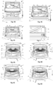
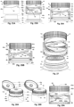
- FIG. 1A, 1B, 1C and 2 depict a first embodiment of the automatic opening device for containers 1 according to the present invention.
- the terms “container” and “packaging” may be used in this specification in an interchangeable manner.
- the automatic opening device for containers 1 comprises a closing element 1a, a base element 1b and a locking device 6.
- the closing element 1a is in the closed position, engaged into the base element 1b, as depicted in Figure 1A , and both are connected each other by means of a pivoting connection element 7, as shown in more detail in Figure 2 .
- a protruding sealing element 4 is provided in the inner central portion of the upper element 8 of the closing element 1a.
- the sealing protruding element 4 is designed to house into the protruding ring 2 and to close the throughout orifice 2a of the base element 1b when the closing element 1a and the base element 1b are closed.
- An internal screw thread 5 is provided in the inner portion of the first sidewall 11 of the base element 1b.
- the internal screw thread 5 comprises an internal orientation screw thread to the right of three starts, depicted in the Figure by means of three internal screw thread flanks 5.
- the internal screw thread 5 may comprise a screw thread with any number of starts and consequently, and so the invention is not limited to the use of an internal screw thread 5 with three starts.
- an external right hand oriented screw thread, with three starts is exclusively due to the fact that this is the embodiment used in the internal screw thread flanks 5 of the base element 1b.
- the same above comments are valid here, in which the use of a right hand screw thread with three starts is only a possibility to carry out the invention, which evidently is not limited to the use of a screw thread of three starts, as well as the screw thread may be right or left hand oriented.
- the external screw thread 14 can be a screw thread with any number of starts, and its orientation can be indistinctly to the right, as shown in Figure 3 , or to the left, as long as it is compatible with the screw thread used in the internal screw thread 5.
- a sealing element 19 is affixed to the rim of the spout 12.
- the elongated cylindrical body 13 of the spout 12 is also provided in its outer portion with an upper ring 16, an intermediate ring 18 and a lower ring 17, located in the upper, intermediate and lower regions, respectively.
- the diameter of the upper ring 16 is smaller than the diameter of the intermediate ring 18, and the diameter of the intermediate ring 18 is smaller than the diameter of the lower ring 17, as can be seen in Figure 3 .
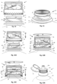
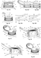
- Figures 4A , 4B, 4C and 4D show a sequence of a process for applying the automatic opening device for containers 1 to the spout 12 of the container 20 provided with a sealing element 19.
- the internal screw thread flanks 5 of the base element 1b located in the front portion of the device for the automatic opening device for containers 1 were not cut.
- the automatic opening device for containers 1 must be made of a relatively resilient material, a thermoplastic, for example, and so, elements of the automatic opening device for containers 1 located in regions where occur interference with elements of the spout 12 undergo temporary elastic deformations, thereby allowing the continuity of the process to apply the automatic opening device for containers 1 in the spout 12.
- FIG 4A An automatic opening device for containers 1 can be seen in Figure 4A , whose geometric axis is aligned with the geometric axis of the spout 12, in a position to start the operation to apply the automatic opening device for containers 1 to the spout 12.
- Figure 4B the automatic opening device for containers 1 is depicted in a position immediately before the beginning of its engagement to the spout 12.
- Figure 4C the automatic opening device for containers 1 is almost completely engaged in the spout 12. It is important to observe in this Figure that the lower regions of the lower locking elements 6b of the locking device 6 initiate contact with the upper face of the intermediate ring 18.
- Figures 6A, 6B, 6C and 6D depict upper perspective views, in partial cut, showing a sequence of the process for opening the container 20 by means of the automatic opening device for containers 1.
- the internal screw thread flanks 5 of the base element 1b had not been cut in Figures 6A, 6B, 6C and 6D .
- the cutting device 3 also does not appear in cut, thereby making possible to see it in its entirety.
- FIG 6A the automatic opening device for containers 1 is depicted in the final position after being applied to container 20, an operation carried out in a factory.
- a user In order to start the process to open the container 20 a user must apply a clockwise rotary movement to the upper portion of the automatic opening device for containers 1, formed by the closing element 1a and the base element 1b, as indicated by the circle T in the Figures.
- Figure 7 depicts an upper rupture element 6a which was torn at the beginning of the rotary movement of the automatic opening device for containers 1, part of the rupture element 6a being attached to the inner portion of the upper edge of the locking element 6, as shown in the upper part of the drawing, and the remaining part keeping attached to the inner portion of the lower edge of the base element 1b, as shown in the lower part of Figure 7 , indicated by the ellipses S.
- the cutting elements 3a of the cutting device 3 had already made the tearing of the sealing element 19. Consequently, the product into the container 20 can be poured through the protruding hollow body of the cutting device 3 and the throughout orifice 2a, pivoting first the closing element 1a to enable the product stored in the container 20 to pass through the throughout orifice 2a.
- both the outer face of the second sidewall 9 of the closing element 1a and the outer face of the first sidewall 11 of the base element 1b of the automatic opening device for containers 1 are provided with means that increase the friction coefficient thereof, consequently facilitating the handling of the automatic opening device for containers 1 by users.
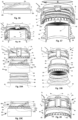
- Figure 8A depicts a first variation of the automatic opening device for containers 1, in which the internal screw thread flanks 5 are bipartite, and comprise an upper section 5s and a lower section 5i. The intermediate portion of each internal screw thread 5 was removed, as can be seen in Figure 8A .
- Figure 9A depicts a front partial cutting view of a second variation of the automatic opening device for containers 1, in which the upper end 21 of the internal screw thread flanks 14b extend beyond the upper ring 16 to a shorter extent than the length observed in Figures 4A , 4B, 4C and 4D , and the lower flank 14a has its upper end facing with the lower portion of the upper ring 16, as can be seen in Figure 9A .
- the locking elements 6b of the locking device 6 are designed in such a way that their upper ends maintain a gap in relation to the lower face of the intermediate ring 18, as indicated by the circles P in Figure 9A .
- the clearance between the upper ends of the locking elements 6b of the locking device 6 in relation to the lower face of the intermediate ring 18 must be designed so that it is sufficient to allow the internal screw thread flanks 5 to move past the upper end 21 of the upper flanks 14b.
- the gap has an extension greater than the vertical extension H that the upper ends 21 of the upper flanks 14b raise beyond the upper ring 16, as shown in Figure 9B . Therefore, in the event that the user applies an anti-clockwise rotation to the upper portion of the automatic opening device for containers 1, the gap between the upper ends 21 of the upper flanks 14b in relation to the lower face of the intermediate ring 18 will always allow that the upper ends 21 of the upper flanks 14b may extend beyond the upper ring 16, as can be seen by the circles T shown in Figure 9B .
- Figure 10 depicts a third variation of the first embodiment of the automatic opening device for containers 1.
- the internal screw thread flanks 5 comprise a left hand oriented screw thread, this being the only difference between the first embodiment and this variation.
- the spout 12 be provided with an external screw thread 14 with left hand orientation, as shown in Figure 10.
- Figure 11 depicts in more detail this spout with left angle orientation.
- open the container means to tear the sealing element that is applied to the rim of the spout of a container to protect its contents, thereby allowing the product into the container to be removed. Notice that, according to the teachings of the invention, once the user has opened the container, there is no need to execute any further action, and the product stored in the container can be served immediately.
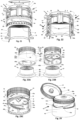
- Figures 12A, 12B and 12 C depict front views, in partial cut, of a fourth variation of the automatic opening device for containers depicted in Figures 1A, 1B, 1C and 2 .
- the difference observed in this variation is the provision of a locking device 6' of lesser longitudinal extension, as can be seen in the Figures, due to a partial screwing of the internal screw thread flanks 5 in the roots 15 of the external screw thread 14, as will be noted from the following description made in the next paragraphs.
- the locking device 6' comprises an elongated and substantially cylindrical body provided at its upper edge with a plurality of upper rupture elements 6a', as can be seen in more detail in Figure 12A , the upper rupture elements 6a' being connected to the lower edge of the base element 1b.
- a plurality of lower locking elements 6b' is provided in the lower inner portion of the locking device 6'.
- the same comments regarding the characteristics of the internal screw thread 5 and the external screw thread 14 apply to the fourth variation of the automatic opening device for containers depicted in Figures 12A, 12B and 12 C .
- the internal screw thread 5 and the external screw thread 14 comprise screw threads of multiple starts of right hand orientation.
- single or multiple screw threads having right or left hand orientation can be used.
- this fourth variation of the automatic opening device for containers 1 to the spout 12 is made at a factory, by means of an equipment not shown in the Figures, which executes a sequential pressing and rotating process. Initially, a downward longitudinal movement is applied to the automatic opening device for containers 1, as indicated by the arrow M in Figure 12A , whereby the lower part of the automatic opening device for containers 1 is pressed against the upper part of the spout 12 until the lower regions of the lower locking elements 6b' touch the upper region of the intermediate ring 18.
- the lower locking elements 6b' must be designed to make them strong enough to preclude any attempt to unscrew the automatic opening device for containers 1 in the spout 12, especially if right hand oriented screw threads are used in the internal screw thread flanks 5 and in the external screw thread 14.
- the difficulty users would face to apply a counterclockwise rotary movement to the automatic opening device for containers 1 would serve to draw their attention to the remarks in the upper region of the closing element 1a, which indicate that the correct rotational movement must be in a clockwise direction to open the container.
- FIGS 13A and 13B depict, respectively, an upper perspective view and an upper cutting perspective view of a fifth variation of the automatic opening device for containers 1, in which the base element 1b is provided with a suction spout 24, which comprises a hollow body which extends above the base element 1b and encircles the throughout orifice 2a.
- the suction spout 24 is provided at its upper end with a mouth ring 24a, and the protruding sealing element 4 of the upper element 8 of the sealing element 1a is designed to house in the mouth ring 24a and to close the throughout orifice 2a of the base element 1b when the closing element 1a and the base element 1b are closed.
- Containers provided with suction spouts are normally used to store liquids that are usually consumed by users when they are on the move, cases of cyclists, long-distance runners or even people who prefer to consume the product stored in the container while on the move
- the assembling of the automatic opening device for containers 1 and the opening of the container 20 are carried out exactly in the same manner as described hereinbefore, since all the other components of this variation are the same as previously described.
- this fifth variation can be combined with any of the variations of the first embodiment of the invention described hereinbefore. If it is made a combination of the third variation with the fifth variation, it will only be necessary to make the necessary to make some modifications due to the use of a left hand oriented screw thread.
- Figures 14A and 14B respectively depict a front view, in partial cut, and a upper perspective view, in partial cut, which show details of a spout adapter device intended to serve as an interface for the application of an automatic opening device for containers 1 in a spout provided with an external screw thread which is different from the internal screw thread of the automatic opening device for containers 1.
- a sealing element 19 is affixed to the rim of the spout 26. External upper end of the spout 26 is provided with an external screw thread 30, a retaining ring being located below the external screw thread 30.
- the automatic opening device for containers 1 depicted in Figures 14A and 14B does not form part of the invention but is substantially similar to the one that has been described regarding Figures 4A , 4B, 4C and 4D , and therefore it is not necessary to repeat the description herein. Any of the previous variations of the automatic opening device for containers 1 described hereinbefore could have been depicted in Figures 14A and 14B , which would normally operate in conjunction with the spout adapter device 25, meaning that there are no limitations for the use of any type of automatic opening device for containers 1 in conjunction with the spout adapter device 25.
- the lower external region of the spout 26 is provided with a base ring 28, larger in diameter than the retaining ring 33.
- the external screw thread 30 depicted in Figures 14A and 14B has a shape different from the internal screw thread 5 of the automatic opening device for containers 1.
- a screw thread of a single start having a right hand orientation, although other types of screw threads could be used, such as, for example, a multiple start screw thread and/or a left hand oriented screw thread.
- the spout adapter device 25 comprises an upper portion 25s rigidly connected to a lower portion 25i, of larger diameter, both being substantially cylindrical portions.
- the upper outer region of the upper portion 25s is provided with a protruding ring 25c, located near to the upper edge of the spout adapter device 25, and an external screw thread 27, the latter comprising a lower flank 27a and an upper flank 27b.
- a root 27c is formed between the lower flank 27a and the upper flank 27b.
- a three starts right hand oriented screw thread is shown in the Figures 14A, 14B and 14C , merely for exemplification. However, a screw thread with any number of starts could be used.
- the upper flank 27b of the external screw thread 27 has an upper end 31 that extends beyond the protruding ring 25c, in order to facilitate the screwing of the external screw thread flanks 5 of the automatic opening device for containers 1 in the root 27c, as will be seen hereafter.
- the lower flank 27a has the upper end levelled with the lower portion of the protruding ring 25c.
- An internal screw thread 29 is provided in the inner region of the upper portion 25s of the spout adapter device 25, as can be seen in Figures 14B, 14C and 14D .
- This internal screw thread 29 is sized to engage the external screw thread 30 of the spout 26, as will be seen hereafter.
- an internal screw thread 29 of one start is depicted in the Figures, although a multiple start screw thread could be depicted.
- the inner lower region of the lower portion 25i is provided with a plurality of lower locking elements 25a, each of them located in front of openings 25b formed in the lower portion 25i, as can be seen in the Figures.
- the lower locking elements 25a are similar to the lower locking elements 6b of the locking device 6, and comprise circularly distributed and spaced apart lugs, the lower portion of each lug being joined to the lower region of the lower portion 25i of the spout adapter device 25, and the body of each lug being tilted towards the geometric axis of the spout adapter device 25.
- the automatic opening device for containers 1 must be applied to the spout adapter device 25 by means of a pressing process, a downward longitudinal movement wherein the lower part of the automatic opening device for containers 1 is pressed against the top of the spout adapter device 25, thereby causing a strong assembly between them.
- This application will be made in a factory.
- the lower locking elements 6b of the locking device 6 should fit into the openings 25b formed in the lower portion 25i of the spout adapter device 25, which are in front of the lower locking elements 25a. Thereby the lower locking elements 6b and the lower locking elements 25a will be facing each other, as shown in Figure 15 .
- Figure 17 depicts an assembly formed by the automatic opening device for containers 1 and the spout adapter device 25 both already assembled each other in a position immediately prior to the beginning of the application of the assembly to the spout 26.
- This application is made in a factory by means of a rotating applicator, not shown in Figure 17 , which applies a clockwise rotation to the assembly, as indicated by circle G in the Figure.
- Figure 18 depicts the assembly formed by the automatic opening device for containers 1 and the spout adapter device 25 duly applied to the spout 26. Notice that the lower locking elements 25a of the spout adapter device 25 had already passed over the retaining ring 33 of the spout 26 at the end of the process to apply said assembly to the spout 26. Consequently, the container 20 will be ready to for sale, to be opened later by a user.
- Figures 19A, 19B and 19C depict an exploded front view, in partial cut, an upper perspective view, in partial cut, and a front view, respectively, showing an alternative embodiment, not covered by the appended claims, of a spout adapter device 35 to be used in conjunction with the automatic opening device for containers 1.
- the spout adapter device 35 comprises an upper portion 35s, a medial portion 35m and a lower portion 35i.
- the upper flank 37b of the external screw thread 37 has an upper end 32 extending beyond the protruding ring 35c, intended to facilitate the screwing of the external screw thread flanks 5 of the automatic opening device for containers 1 in the roots 37c, as will be seen hereafter, while the lower flank 37a has its upper end facing with the lower portion of the protruding ring 35c.
- a rim 34 is provided in the lower region of the upper portion 35s of the spout adapter device 35.
- the medial portion 35m is shaped like a trunk-cone and its upper portion is connected to the lower region of the rim 34, while its lower region is connected to the upper region of the lower portion 35i.
- the medial portion 35m is provided with a plurality of spaced apart and circumferentially distributed radial openings 35a.
- a internal screw thread 36 having one start is provided in the inner portion of the lower portion 35i of the spout adapter device 35. This internal screw thread 36 is sized to screw to the outer screw thread 30 of the spout 26, as will be seen hereafter.
- a plurality of lower locking elements 35b is provided in the lower inner region of the lower portion 35i, similar to the lower locking elements 25a of the spout adapter device 25, the lower locking elements 35b comprising a plurality of spaced apart lugs distributed circularly, the lower portion of each lug being joined to the lower region of the lower portion 35i of the spout adapter device 35, and the body of each lug being tilted towards the geometric axis of the spout adapter device 35.
- the lower locking elements 35b are able to bend slightly towards the inner wall of the spout adapter device 35 when it is connected to the spout 26, as will be seen hereafter.
- the automatic opening device for containers 1 must be applied to the spout adapter device 35 by means of a pressing process, a downward longitudinal movement in which the lower part of the automatic opening device for containers 1 is pressed against the top of the spout adapter device 35, which causes a forced assembly between them.
- This application will be made in a factory.
- the lower locking elements 6b of the locking device 6 will be pressed by the rim 34 of the spout adapter device 35, and consequently will tend to incline towards the internal wall of the locking device 6, thereby allowing the automatic opening device for containers 1 to make a downward longitudinal movement.
- FIG. 20 depicts a perspective view in cut wherein the automatic opening device for containers 1 is totally applied to the spout adapter device 35.
- the lower locking elements 6b of the locking device 6 should fit into the radial openings 35a of the medial portion 35m of the spout adapter device 35, as shown in Figure 20 .
- Figure 21 shows the assembly formed by the automatic opening device for containers 1 already applied to the spout adapter device 35, in a position immediately before starting the application of said assembly to the spout 26.
- This application will be made in a factory by means of a rotating applicator, not shown in Figure 21 .
- Said applicator applies a rotation to the assembly, in this case, a clockwise rotation, as indicated by circle J in the Figure.
- Figure 22 is an upper perspective cutting view showing the assembly formed by the automatic opening device for containers 1 and the spout adapter device 35 duly applied to the spout 26.
- the lower locking elements 35b of the device spout adapter 35 had passed the retaining ring 33 of spout 26 at the end of the process to apply said assembly to the spout 26. Therefore, the container 20 will be ready for sale and to be subsequently opened by a user.
- the external screw thread 27 of the spout adapter device 25, shown in Figures 14A, 14B, 14C and 14D , and the external screw thread 37 of the spout adapter device 35, shown in Figures 19A and 19B can both be left hand oriented screw threads if an automatic opening device for containers 1 is used in case the internal screw thread 5 is a left hand oriented screw thread.
- Figures 23A, 23B, 23C and 24 depict views of a further embodiment of the invention, showing an automatic opening device for containers 41 to be applied to a spout 47 of a container 51.
- the spout 47 comprises an elongated cylindrical body 48, a first upper ring 49 and a second lower ring 50, larger in diameter than the first upper ring 49.
- a sealing element 19 adheres to the upper rim of the spout 47.
- the upper external region of the cylindrical body 48 from the upper rim of the spout 47 to the first upper ring 49 is smooth, meaning that there is no screw thread there.
- the automatic opening device for containers 41 comprises a closing element 41a, a base element 41b and a guiding and locking device 46.
- the closing element 41a is in the open position, and the connection between the base element 41b and the closing element 41a is made by a pivoting connecting element, not shown in the Figure, a connection similar to that used between the closing element 1a and the base element 1b previously described in relation to Figures 1A, 1B and 1C and 2 .
- the base element 41b comprises a first sidewall 54 and an upper member 55 whose edges are joined to the upper edge of the first sidewall 54.
- a central protruding ring 39 is provided in the upper central portion of the upper member 55, which encircles a throughout orifice 39a.
- An external screw thread 45 is provided in the lower external portion of the first sidewall 54 of the base element 41b.
- an external screw thread with three starts is shown, for a exemplification only, as other types of screw threads may be used. It can be seen in the Figures the external screw thread flanks 45. Henceforth the expressions "external screw thread 45" and “external screw thread flanks 45" will be used to refer to the same screw thread.
- the closing element 41a comprises a second sidewall element 56, in the form of an elongated cylindrical body, and an upper member 57, circularly shaped, whose edges are joined to the upper edge of the second sidewall element 56.
- a protruding sealing element 40 is provided in the inner central portion of the upper member 55 of the sealing element 41a.
- the sealing protruding element 40 is designed to house the protruding ring 39 and to close the throughout orifice 39a of the base element 41b when the closing element 41a and the base element 41b are closed.
- the guiding and locking device 46 shown in partial cut in Figures 23A, 23B, 23C and 24 , comprises an elongated cylindrical body whose upper inner portion is provided with an internal screw thread 44, in the Figure a three starts screw thread comprising a lower flank 44a and an upper flank 44b, with a root 44c formed between these two flanks.
- the flanks of the internal screw thread 44 of the guiding and locking device 46 are shown in the Figures, which would not appear in a cutting view.
- the upper ends 44d of the upper flanks 44b extend above the upper ends of the lower flanks 44a to facilitate the screwing of the external screw thread flanks 45 in the roots 44c.
- Reinforcement lugs 46d are provided on the upper edge of the guiding and locking device 46, located in the regions where the upper ends 44d of the upper flanks 44b are extended, thereby providing support for the upper ends 44d at the moment when the starts 45a of the external screw thread flanks 45 touch the upper ends 44d, as will be seen hereafter.
- a plurality of lower locking elements 46b are provided in the lower region of the inner portion of the guiding and locking device 46, which comprise spaced apart lugs distributed circularly, the lower portion of each lug being joined to the lower region of the inner portion of the guiding and locking device 46, and the body of each lug being pivoted towards the geometric axis of the guiding and locking device 46.
- a plurality of upper rupture elements 46a connects the upper region of the guiding and locking device 46 to the lower edge of the base element 41b, as outlined by circle F in Figure 23C .
- a plurality of guiding fins 46c can also be seen in the Figure, provided in the lower inner portion of the guiding and locking device 46. These guide fins 46c are optional and serve to facilitate the insertion of the guiding and locking device 46 in the spout 47, thereby positioning it correctly.
- the screw thread 45 provided on the lower external portion of the first sidewall 54 of the base element 41b, and the internal screw thread 44 provided on the upper internal portion of the guiding and locking device 46 comprise a screw thread with three starts.
- a cutting device 43 is provided in the lower central portion of the upper member 55 of the base member 41b, the cutting device 43 comprising a hollow protruding body whose upper portion is connected to the lower central portion of the upper member 55 in the region where it is located the throughout orifice 39a, the latter being a continuation of the hollow portion of the cutting device 43.
- the lower portion of the cutting device 43 is provided with a plurality of cutting elements 43a.
- the automatic opening device for containers 41 is in a position immediately prior to the beginning of its application to the spout 47, which is made by pressing the lower portion of the automatic opening device for containers 41 against the upper portion of the spout 47, an operation performed in a factory by means of an applicator not shown in Figures 25A and 25B .
- Figure 26A is a partial front view showing the automatic opening device for containers 41 duly applied to the spout 47. Notice that the lower locking elements 46b of the guiding and locking device 46 had passed the first upper ring 49 at the end of the process of applying the automatic opening device for containers 41 to the spout 47. Consequently, the container 51 will be ready for sale and to be subsequently opened by a user.
- Figure 27 is a partial perspective cutting view depicting a variation of the automatic opening device for containers 41, in which the only difference regarding the automatic opening device for containers 41 depicted in Figures 23A, 23B, 23C and 24 is that the lower region of the guiding and locking device 46 is provided with an internal screw thread 52.
- This variation of the device for the automatic opening device for containers 41 can be used in containers provided with threaded spouts.
- the spout 26 of the container 20 shown in Figure 27 is provided with a single start screw thread with right angle orientation.
- screw threads having more than one start can be provided to the spout 26, as well as left hand oriented screw threads can be used.
- the internal screw thread 52 of the automatic opening device for containers 41 must be screwed onto the screw thread 30 of the screwed spout 26 by means of a rotating applicator, an operation executed in factory.
- the operation to open the container 20 is to be executed by users in the same manner as described hereinbefore. Users are unlikely to even notice the differences between the modalities of the automatic opening device for containers 41 used in a container, whether the one depicted in Figure 27 or the one depicted in Figures 23A, 23B, 23C and 24 .
- Figures 28A and 28B are perspective views depicting alternative embodiments for the guiding and locking device 46 of the automatic opening device for containers 41.
- the guiding and locking device 46 is not provided with reinforcement lugs 46d (shown in the embodiment of Figures 25A and 25B ).
- the upper ends 44d of the upper flanks 44b must be designed to withstand the stress to which they will be subjected at the moment of starting the operation to open the container, when they will come in contact with the starts 45a of the external screw thread flanks 45.
- FIGS 29A and 29B for exemplification only, use is made of a three starts screw thread.
- the screw threads 144 and 145 can be of single or multiple starts, and, in this case, the internal screw thread 145 will then comprise a plurality of internal screw thread flanks.
- left hand oriented screw threads were depicted in the Figures of the previously described embodiments of the automatic opening device for containers 41, left hand oriented screw threads can be used instead, as mentioned regarding the embodiments of the invention described hereinbefore.
- FIGS 30A and 30B are front cutting views showing an automatic opening device for containers 41 provided with left hand oriented screw threads, similar to those depicted in Figures 29A and 29B .
- Figures 31A and 31B depict a front partial cutting view and a partial front perspective cutting view depicting an additional embodiment of an automatic opening device for containers 61 according to the teachings of the present invention.
- the automatic opening device for containers 61 comprises a closing element 61a, a base element 61b and a locking device 62.
- the closing element 61a is in a closed position, engaged to the base element 61b.
- both are connected to each other by means of a pivoting connection element, not shown in the Figures.
- This type of pivoting connection between base elements and closing elements is well known in the art, variations thereof being known, and can be used interchangeably in conjunction with the present invention.
- Any other connection means can be used to connect the closing element 61a to the base element 61b, and there may even be no connection means between them, and the connection between these two parts could be made by pressure, or by screwing, for example.
- the base element 61b comprises a first sidewall 72, in the form of an elongated cylindrical body, and a top element 73, circularly shaped and whose edges are joined to the upper edge of the first sidewall 72.
- the closing element 61a is also similar to the closing elements 1a and 41a described hereinbefore and comprises a second sidewall 71, in the form of an elongated cylindrical body, and an upper element 75 circularly shaped and whose edges are joined to the upper edge of the second sidewall 71.
- a cutting device 63 is provided in the inner region of the top element 73, the cutting device 63 comprising a protruding hollow body which projects downwardly, as shown in Figure 31A , its lower portion being provided with a plurality of cutting elements 63a. In Figures 31A and 31B the cutting device 63 does not appear in cut so as to allow to view it in its entirety.
- the top element 73 is provided in its upper region with a protruding ring 74, which encircles a throughout orifice 74a.
- the upper region of the cutting device 63 is connected to the lower portion of the top element 73, in the region where the throughout orifice 74a is located, the latter being a continuation of the hollow portion of the cutting device 63.
- the throughout orifice is not viewed in the Figure, the throughout orifice 74a being shown in the Figure in dashed lines, to indicate its location in the top element 73 in alignment with the hollow portion of the cutting device 63.
- a protruding sealing member 76 is provided in the inner portion of the upper member 75 of the closing member 61a.
- the protruding sealing member 76 is designed to house the protruding ring 74 when the closing element 61a and the base element 61b are closed, wherein the protruding sealing member 76 closes the throughout orifice 74a of the base element 61b, as shown in Figures 31A and 31B .
- the second sidewall 71 of the closing element 61a and the first sidewall 72 of the base element 61b of the automatic opening device for containers 61 have substantially equal outside diameters when closed, as shown in Figure 31A . Therefore, the top element 73 of the base element 61b must be provided with a recess in the region of its edge at which it connects to the first sidewall 72, to form an annular ring region 73a. Thus, when the closing element 61a is in the closed position, the lower region of the second sidewall 71 will engage to the annular ring region 73a, as can be seen in Figure 31A .
- This feature is only intended to facilitate the manipulation of the automatic opening device for containers 61 by users, serving only to facilitate the use of the device.
- the configurations of the closing element 61a and the base element 61b can be different from those depicted in the Figures, provided that these different components do not cause difficulties for the operation of the automatic opening device for containers 61.
- the locking device 62 comprises an elongated substantially cylindrical body provided at its upper edge with a plurality of upper rupture elements 62a connected to the lower edge of the base element 61b, as can be seen in the Figures.
- a plurality of lower locking elements 62b is provided in the lower inner portion of the locking device 62.
- rupture elements may be used on the upper rupture elements 62a, provided that they are able to cause the same effects obtained by the rupture elements depicted in the Figure.
- the automatic opening device for containers 61 should be screwed onto a spout 65 provided in a container 70.
- the spout 65 comprises an elongated cylindrical body 66 provided in its outer region with an external screw thread 67.
- the internal screw thread 64 of the base element 61b will screw onto the external screw thread 67 of the spout 65, as will be seen hereafter.
- An upper ring 68 is provided in the outer region of the elongated cylindrical body 66, below the outer screw thread 67, and a lower ring 69 is provided in the lower outer region of the elongated cylindrical body 66, as can be seen in the Figures.
- the spout 65 is provided in its rim with a sealing element 77, as shown in Figure 31B .
- the automatic opening device for containers 61 is in a position immediately prior to starting its application to the spout 65.
- the application starts by inserting the lower portion of the automatic opening device for containers 61 against the upper portion of the spout 65, by making a linear downward movement as indicated by the arrow N in Figure 31B .
- This operation will cease when the automatic opening device for containers 61 is in a position where a rotational movement can be initiated, to cause the internal screw thread 64 of the base element 61b to screw in the external screw thread 67 of the spout 65.
- This operation is executed in a factory, using an applicator not shown in Figures 31A and 32B .
- Figure 31C depicts the automatic opening device for containers 61 partially screwed onto the spout 65, after the rotational screwing movement has started, as indicated by circle B. More particularly, the Figure depicts the moment of starting the rotational screwing movement, when the lower locking elements 62b touches the edge of the retaining ring 68. Consequently, the lower locking elements 62b incline towards the internal region of the locking device 62.
- said rotational screwing movement is applied to the automatic opening device for containers 61, it also undergoes a concomitant downward linear movement, as indicated by the arrow N in Figure 31C .
- a particular feature of this embodiment of the invention is that is partial the screwing of the internal screw thread 64 of the base element 61b of the automatic opening device for containers 61 on the external screw thread 67 of the spout 65, as depicted in Figure 31D .
- the use of the lower locking elements 62b is optional, although recommended, as it prevents inadvertent unscrewing of the automatic opening device for containers 61, as described hereinbefore. However, the automatic opening device for containers 61 would operate normally if it were not provided with the lower locking elements 62b.
- This partial screwing is fundamental to facilitate the opening of the container 70 by a user, who will only need to rotate the automatic opening device for containers 61 in a clockwise direction, thereby causing the tearing of the upper rupture elements 62a. Consequently, the screwing of the internal screw thread 64 of the base element 1b of the automatic opening device for containers 61 on the external screw thread 67 of the spout 65 will go on.
- Some aspects are relevant for designing the automatic opening device for containers 61, to enable it to operate correctly to open container 70.
- One of these relevant aspects is to design the lower locking elements 62b in such a way that, after they had move past the edge of the locking ring 68, they must resist any attempts to unscrew the automatic opening device for containers 61.
- An aspect of fundamental importance for the correct operation of the automatic opening device for containers 61 to open container 70 is the correct sizing of some components of the automatic opening device for containers 61 object of this embodiment of the invention, particularly the base element 61b and the locking device 62, as will be seen hereafter.
- the spout 65 has a linear extension L 1 between its rim and the edge of the retaining ring 68, and a linear extension C 1 between said edge of the retaining ring 68 and the portion of the upper region of the lower ring 69 where the lower edge of the locking device 62 will touch, at the end of the assembly of the automatic opening device for containers 61 on the container 70, as shown in Figure 31D .
- the base element 61b has a linear extension L2 between the lower part of the annular ring region 73a and its lower rim, and a linear extension C2 between that lower edge of the base element 61b and an imaginary plane that contains the upper region of the lower locking elements 62b.
- the linear extension L3 represents the displacement of the linear extension of the spout 65 between its edge and the edge of the retaining ring 68 inside the automatic opening device for containers 61, after the device is in the final position of its application to the spout 65.
- the linear extension C3 represents the spacing between the edge of the spout 65 and the lower part of the annular ring region 73a of the upper member 73.
- Figures 32A and 32B are upper perspective views showing an automatic opening device for containers 41 whose base element 41b is provided with a pouring device 53.
- the closing element 41a is in the open position
- in Figure 32B is in the closed position, in a partial cut.
- the pouring device 53 comprises an integrally hollow body formed by a first curved portion 53a and a second portion 53b.
- the first curved portion 53a has one end connected to the hollow body of the cutting device 43 (not shown in the Figures), and its other end is connected to one end of the second horizontal portion 53b, the latter extending over the face of the base element 41b towards the edge, as shown in Figure 32A .
- the other end of the second horizontal portion 53b is bevelled and forms a rim 53c, which defines a throughout orifice 53d.
- the sealing element 41a' prevents the possibility for the product to flow through the throughout orifice 53d and accumulate inside the empty space formed between the closing element 41a and the base element 41b. In case the sealing element 41a' were not provided, when a user would open the closing element 41a, an undesirable product spill would occur.
- This embodiment of the pouring device 53 enables a user to pour the product stored in the container without having to place the container upside-down, in a position where the throughout orifice is substantially downwards, which can cause the product to overflow, in special thixotropic products.
- the pouring device 53 may be used in conjunction with any of the embodiments and variations of the invention described hereinbefore. Therefore, mutatis mutandis, the automatic opening device for containers 1 shown in Figures 1A to 12 and Figures 14A to 22 may also be provided with a pouring device 53.
- the automatic opening device for containers is provided with a closing element and a base element, joined by a pivoting connecting element.
- the closing element can be attached to the base element by means of a screw thread, or by means of a pressure coupling, as previously mentioned.
- the embodiments of the automatic opening device for containers disclosed hereinbefore be provided with only the base elements 1b, 41b or 61b.
- the throughout orifice for the administration of the product would be permanently open, without a seal.
- the upper member 10 of the base element 1b may be provided with a protruding plugging element 58 formed by an elongated hollow body whose upper portion is closed, and the bottom portion is open and firmly connected to the base element 1b, with the hollow portion of the protruding plugging element 58 being aligned and in communication with the throughout orifice 2a and, consequently, with the hollow portion of the cutting device 3.
- a cutting element such as a knife
- a transverse cut across section the body of the protruding plugging element 58 to provide a throughout orifice, in order to allow the product stored in the container to pass through hollow portion of the protruding plugging element 58.
- a cap 59 can be provided to close this throughout orifice in the hollow portion of the protruding plugging element 58, in order to prevent that passage from being permanently open.
- the cap 59 is connected to the base element 1b by means of a flexible connecting element 60, to prevent the cap 59 from being inadvertently discarded by the user.
- FIGS 34A and 34B depict perspective views showing an exemplary rotational locking system that can be used in conjunction with any of the automatic opening devices for containers described hereinbefore.
- said rotational locking system is described in conjunction with the embodiment of the automatic opening device for containers 41 shown in Figures 23A, 23B, 23C and 24 . It is important to mention that, mutatis mutandis, this rotational locking system can also be used in the automatic opening devices for containers 1 and 61 described hereinbefore.
- FIGS 34A and 34B depict an external screw thread flank 45 being screwed onto the internal screw thread 44.
- Each of the external screw thread flanks 45 is provided with a locking recess 45b to preclude rotational movements, which is designed to latch into a locking protrusion 44e provided in one of the flanks of the screw thread 44, thereby preventing rotational movements.
- each rotational locking recess 45b and each rotational locking protrusion 44e must be determined in such a way that the latch between them occurs at the same time as the inner portion of the upper member 55 of the base member 41b touches the edge of the spout 47. Therefore, when a user opens the container, by means of a clockwise rotation of the assembly formed by the closing element 41a and the base element 41b, at the moment when the rotational locking recesses 45b latches into the locking protrusion 44e of the screw thread 44, the user will hear a snap. From that moment on no rotation will occur, in any direction, as the whole assembly is locked in that position.
- the rotational locking system depicted in Figures 34A and 34B prevents the assembly formed by the closing element 41a and the base element 41b from rotating to unscrew the screw thread 44 in an anti-clockwise direction. It therefore serves as a tamper resistant means that precludes removal of that assembly formed by the closing element 41a and the base element 41b, thereby preventing the container from being refilled after the product originally stored in the container has been fully poured.
- a container is provided with an automatic opening device for containers according to the invention in which there is no connecting element to hold the closing element 1a or 41a, or the cap 59, connected to the base element 1b, or 41b, it is recommended that an tamper evidence device is used to cover the automatic opening device for containers, thereby preventing the closing elements 1a, 41a, 61a or the cap 59 from being improperly removed when the container is in market shelves.
- Figure 35 shows an automatic opening device for containers 81 according to a further embodiment of the invention.
- the automatic opening device for containers 81 comprises a closing element 81a, a base element 81b and a locking device 6.
- the automatic opening device for containers 81 is quite similar to the automatic opening device for containers 1 shown in Figures 1A, 1B and 1C .
- the closing element 81a when is in the closed position, engage with the base element 81b, and both are connected to each other by means of a pivoting connection element 86, as shown in Figure 35 .
- a pivoting connection element 86 there are variations of this type of pivoting connection, which can be used interchangeably in conjunction with the present invention.
- any other type of connection means can be used to connect the closing element 81a to the base element 81b, and there may even be no connection means between them, in which case the connection between these two parts could be made by pressure or screwing, for example.
- the base element 81b comprises a first sidewall 78, in the form of an elongated cylindrical body, and a circularly shaped top element 79 whose edges are joined to the upper edge of the first sidewall 78.
- the upper region of the top element 79 is provided with a protruding element 84, located in a region close to the edge of the top element 79, preferably located 180° from the region where the connecting pivoting element 86 connects the base element 81b with the closing element 81a, although other locations can be chosen.
- the protruding element 84 encircles a throughout orifice 83.
- the closing element 81a comprises a second sidewall 80 in the form of an elongated cylindrical body and an upper element 82, circular in shape and whose edges are joined to the upper edge of the second sidewall 80.
- a protruding sealing element 85 is provided in the lower region of the upper element 82, intended to close the throughout orifice 83 of the base element 81b when the closing element 81a and the base element 81b are closed.
- the protruding sealing element 85 can be designed to encircle the protruding element 84, or, alternatively, engage with the throughout orifice 83 to create a sealing.
- the location of the protruding sealing element 85 in the lower region of the upper element 82 will be a function of the location of the protruding element 84, and in the present case it will be located in a region close to the edge of the upper portion of the upper element 82, preferably located at 180° from the region in which the connecting pivoting element 86 connects the base element 81b to the closing element 81a, although other locations can be chosen.
- the automatic opening device for containers 81 is designed so that the second sidewall 80 of the closing element 81a and the first sidewall 78 of the base element 81b have substantially equal outside diameters when closed.
- the top element 79 of the base element 81b must be provided with a recess in the region of its edge where it connects to the first sidewall 78, to form a ring-shaped engagement region 79a.
- the closing element 81a when the closing element 81a is in the closed position, the lower region of the second sidewall 80 will engage into said ring-shaped engagement region.
- This feature intends to facilitate the manipulation of the automatic opening device for containers 81 by users. It is possible to use different configurations of the closing element 81a and the base element 81b than those depicted in the Figures, without, however, changing the functionality of these components for the operation of the automatic opening device for containers 81.
- the automatic opening device for containers 81 may even be provided without a closing element 81a as shown in Figure 35 , and yet the automatic opening device for containers 81 will operate normally, according to the teachings of the invention.
- an internal screw thread 87 is provided in the inner portion of the first sidewall 78 of the base element 81b.
- the configuration of the internal screw thread 87 may comprise, for example, a right-oriented screw thread with three starts, although the internal screw thread 87 may comprise a screw thread with any number of starts.
- this embodiment of the invention is not limited to the use of an internal screw thread with three starts, and such screw thread was only chosen for exemplification only, although the use of a screw thread with multiple starts is more suitable for the purposes of the invention.
- the internal screw thread 87 may be indistinctly oriented to the right, as shown in the Figures, or to the left.
- the inner portion of the top element 79 is provided with a cutting device 88, which comprises a hollow protruding body whose upper portion is connected to the lower portion of the top element 79 in the region where the throughout orifice 83 is located.
- the latter is a continuation of the hollow portion of the cutting device 88, thereby forming a direct connection substantially between the throughout orifice 83 and the hollow portion of the cutting device 88, through which the product contained in the container will pass.
- the lower portion of the cutting device 88 is provided with a plurality of cutting elements 88a.
- the locking device 6 shown in Figures 35, 36 and 37 is identical to the locking device that has been described in relation to the embodiment of the invention shown in Figures 1A, 1B, 1C and 2 , and comprises an elongated substantially cylindrical body provided in its upper edge of a plurality of upper rupture elements 6a which are connected to the lower edge of the base element 1b, as can be seen in more detail in Figure 1C .
- a plurality of lower locking elements 6b is provided in the lower internal portion of the locking device 6.
- the lower locking elements 6b comprise spaced apart lugs circularly distributed, the lower portion of each lug being joined to the lower region of the locking device 6 and the body of each lug being inclined towards the geometric axis of the locking device 6.
- the lower locking elements 6b are designed so that they can slightly incline radially towards the inner wall of the locking device 6.
- FIG. 36 is provided with a spout 12 which comprises an elongated cylindrical body provided with an external screw thread 14, in the Figure a three-start, right-oriented screw thread, which comprises a lower flank 14a and an upper flank 14b, with a root 15 formed between these two flanks.
- the characteristics of the external screw thread 14 have been described hereinbefore, and for this reason, it will not be repeated here.
- an external right-oriented screw thread with three starts, is because this is the configuration used in the internal screw thread 5 of the base element 81b.
- the same comments presented hereinbefore with this regard are valid here, in that the use of a right-oriented thread with three starts is for exemplification only. Therefore, is evidently that the invention is not limited to use only a three-starts screw thread, be it right or left hand oriented. Therefore, the external screw thread 14 may be a screw thread with any number of starts, and its orientation can be indistinctly to the right, as shown in Figures 36 and 37 , or to the left, as long as it is compatible with the screw thread used in the internal screw thread 87.
- a sealing element 19 is affixed to the rim of the spout 12.
- the spout 12 is also provided in its outer portion with an upper ring 16, an intermediate ring 18 and a lower ring 17, located in the upper, intermediate and lower regions, respectively.
- the diameter of the upper ring 16 is smaller than the diameter of the intermediate ring 18, and the diameter of the intermediate ring 18 is smaller than the diameter of the lower ring 17, as can be seen in Figures 36 and 37 .
- the application of the automatic opening device for containers 81 to the spout 12 is made by means of a pressing process, a downward longitudinal movement, by means of which the lower part of the automatic opening device for containers 81 is pressed against the upper part of the spout 12.
- the process for applying the automatic opening device for containers 81 to the spout 12 of the container 20 is the same as previously described regarding the application of the automatic opening device for containers 1 to the spout 12 of the container 20, and shown in Figures 4A , 4B, 4C and 4D . For this reason, the description of this process will not be repeated here. Consequently, the same observations made hereinbefore regarding the embodiment of the invention referring to Figures 4A , 4B, 4C and 4D are valid here.
- Figure 36 depicts the automatic opening device for containers 81 in the position it remains after being applied to the spout 12 of the container 20, an operation executed in factory. In that position, container 20 is ready for sale.
- a user needs to open the container 20, to pour the product contained therein, suffices to rotate the automatic opening device for containers 81 in order to make the cutting elements 88a of the cutting device 88 tear the sealing element 19, thereby releasing the passage of the product through the hollow portion of the cutting device 88 and through the throughout orifice 83.
- Figure 37 the automatic opening device for containers 81 is depicted in a position after a user has made a rotation that has made the cutting elements 88a of the cutting device 88 cut the sealing element 19, thereby enabling the product to pass through the hollow portion of the cutter 88 and through the throughout orifice 83.
- Figure 38 depicts a top perspective view of a variation of the throughout orifice of the fourth embodiment of the automatic opening device for containers depicted in Figures 35, 36 and 37 .
- the protruding element 84 depicted in the Figure is has an annular shape, which encircles a circular throughout orifice 83. All the remaining components of the automatic opening device for containers 81 shown in Figure 38 are identical to those described in relation to Figures 35, 36 and 37 , and for that reason, the description of these components will not be repeated here.
- the fundamental characteristic of all of them is the provision of a cutting device that, in addition to serving as a cap for the container, is provided with a means for executing a cutting operation of the sealing elements which are usually affixed to the rims of the spouts of the containers, thereby creating a passage to enable the product contained in the container to be poured.
- the shapes of the cutting elements used in the cutting devices of the invention must be determined according to the cutting speed provided by the type of screw thread used in the automatic opening device for containers and the characteristics of the material used in the sealing element.
- Tamper resistant devices may be used in conjunction with the various embodiments and variations of the invention described herein, in order to guarantee the user that the container has not been tampered with.
- thermal wrappers around the spout and the devices can be used, which are provided with tear lines that facilitate their removal, as is well known in the art.
Landscapes
- Engineering & Computer Science (AREA)
- Mechanical Engineering (AREA)
- Closures For Containers (AREA)
Claims (11)
- System zum automatischen Öffnen eines Behälters (20), das eine automatische Öffnungsvorrichtung (1) und einen Ausguss (12) beinhaltet, der an dem Behälter (20) befestigt ist, wobei:der Ausguss (12) einen länglichen Körper (13) umfasst, dessen äußerer Bereich mit einem äußeren unteren Ring (17) und einem äußeren Zwischenring (18) versehen ist, der sich über dem äußeren unteren Ring (17) befindet, wobei der Durchmesser des äußeren unteren Rings (17) größer als der Durchmesser des äußeren Zwischenrings (18) ist;ein äußeres Schraubgewinde (14) von zumindest einem Gewindegang in dem länglichen Körper (13) des Ausgusses (12) über dem äußeren Zwischenring (18) bereitgestellt ist, wobei das äußere Schraubgewinde (14) eine untere Flanke (14a) und eine obere Flanke (14b) umfasst, wobei ein Gewindegrund (15) zwischen diesen zwei Flanken (14a-14b) gebildet ist, wobei die obere Flanke (14b) des äußeren Schraubgewindes (14) ein oberes Ende (21) aufweist;ein Versiegelungselement (19) an dem Rand des Ausgusses (12) befestigt ist;die automatische Öffnungsvorrichtung (1) zumindest ein Basiselement (1b), eine Schneidvorrichtung (3) und eine Verriegelungsvorrichtung (6,6') umfasst;das Basiselement (1b) einen länglichen Körper umfasst, der eine erste Seitenwand (11) bildet, deren Kanten mit einem oberen Element (10) zusammengefügt sind, das mit einer Durchgangsöffnung (2a) versehen ist;der innere Abschnitt der ersten Seitenwand (11) mit einem inneren Schraubgewinde (5) mit zumindest einem Gewindegang versehen ist, das zu dem äußeren Schraubgewinde (14) des Ausgusses (12) passt;die Verriegelungsvorrichtung (6,6') einen länglichen Körper umfasst, der an seiner oberen Kante mit einer Vielzahl von oberen Bruchelementen (6a,6a') versehen ist, die mit einer unteren Kante des länglichen Körpers des Basiselements (1b) verbunden sind, wobei der unterste Bereich der Verriegelungsvorrichtung (6,6') mit einem Verriegelungsmittel (6b) zum Verriegeln der automatischen Öffnungsvorrichtung (1) an dem Ausguss (12) versehen ist, indem das Verriegelungsmittel zwischen dem äußeren unteren Ring (17) und dem äußeren Zwischenring (18) eingefügt wird;die Schneidvorrichtung (3) einen hervorstehenden Hohlkörper umfasst, dessen oberer Abschnitt mit dem unteren Bereich des oberen Elements (10) verbunden ist, der die Durchgangsöffnung (2a) umschließt, wobei der untere Abschnitt der Schneidvorrichtung (3) mit zumindest einem Schneidelement (3a) versehen ist,das System zum automatischen Öffnen eines Behälters dadurch gekennzeichnet ist, dass:der äußere Bereich des Ausgusses (12) zusätzlich mit einem äußeren oberen Ring (16) versehen ist, der sich über dem äußeren Zwischenring (18) befindet, wobei sich das Schraubgewinde (14) zwischen dem äußeren Zwischenring (18) und dem äußeren oberen Ring (16) befindet, wobei der Durchmesser des äußeren oberen Rings (16) kleiner als der Durchmesser des äußeren Zwischenrings (18) ist;das innere Schraubgewinde (5) des länglichen Körpers des Basiselements (1b) und das äußere Schraubgewinde (14) des Ausgusses (12) aus der Gruppe ausgewählt sind, die rechtes Schraubgewinde und linkes Schraubgewinde umfasst;sich das obere Ende (21) der oberen Flanke (14b) des äußeren Schraubgewindes (14) über den äußeren oberen Ring (16) des Ausgusses (12) erstreckt und das obere Ende der unteren Flanke (14a) bündig mit dem unteren Abschnitt des äußeren oberen Rings (16) ist; undwobei Drehung des Basiselements (1b) bewirkt, dass die oberen Bruchelemente (6a) der Verriegelungsvorrichtung (6) brechen und sich das Basiselement (1b) dreht, sodass die Eintrittsspitzen (5a) der inneren Schraubgewindeflanken (5) entlang der oberen Fläche des oberen Rings (16) laufen, bis sie das obere Ende (21) der oberen Flanke (14b) des Schraubgewindes (14) treffen.
- System zum automatischen Öffnen eines Behälters (20) nach Anspruch 1, wobei:
das Verriegelungsmittel zum Verriegeln des Basiselements (2b) der automatischen Öffnungsvorrichtung (1) mit dem Ausguss (12) eine Vielzahl von unteren Verriegelungselementen (6b,6b') in der Form von beabstandeten Laschen, die kreisförmig verteilt sind, umfasst, wobei der untere Abschnitt jeder Lasche mit dem unteren Bereich des unteren Abschnittes der Verriegelungsvorrichtung (6,6') zusammengefügt ist, wobei der Körper jeder Lasche zu der geometrischen Achse der Verriegelungsvorrichtung (6,6') geneigt ist. - System zum automatischen Öffnen eines Behälters (20) nach einem von Anspruch 1-2, wobei:
die Drehung der automatischen Öffnungsvorrichtung (1) in eine falsche Richtung, um den Behälter zu öffnen, durch die Verwendung einer Anordnung angegeben ist, die aus der Gruppe ausgewählt ist, die aus einem Drehbegrenzer (23) und einer Geräuschvorrichtung zum Warnen vor falscher Drehrichtung gebildet ist, wobei:der Drehbegrenzer (23) durch ein Zusammenwirken zwischen einem Führungselement (22), dem oberen Ende (21) der oberen Flanke (14b) des äußeren Schraubgewindes (14) und der Flanke des inneren Schraubgewindes (5) gebildet ist;das Führungselement (22) an einem äußeren Abschnitt des länglichen Körpers des Ausgusses gebildet ist und sich parallel zu der oberen Kante des Ausgusses erstreckt;sich das obere Ende (21) der oberen Flanke (14b) des äußeren Schraubgewindes (14) bis zu dem Führungselement (22) erstreckt, wodurch der Drehbegrenzer (23) zwischen oberem Ende (21) der oberen Flanke (14b) des äußeren Schraubgewindes (14) und dem Führungselement (22) gebildet wird, wobei die Flanke des inneren Schraubgewindes (5) der automatischen Öffnungsvorrichtung (1) zweiteilig ist, einen oberen Abschnitt (5s) und einen unteren Abschnitt (5i) umfasst, wodurch ein Spalt zwischen ihnen gebildet wird;wobei, wenn die Öffnungsvorrichtung (1) in eine falsche Richtung gedreht wird, das Führungselement (22) in der Lage ist, durch den Spalt zwischen dem oberen Abschnitt (5s) und dem unteren Abschnitt (5i) der Flanke des inneren Schraubgewindes (5) zu verlaufen und sich der untere Abschnitt (5i) des inneren Schraubgewindes (5) über die obere Fläche des oberen Rings (16) bewegt, bis sie den Drehbegrenzer (23) in Eingriff nehmen; die Geräuschvorrichtung zum Warnen vor falscher Drehrichtung durch ein Zusammenwirken zwischen dem oberen Ende (21) der oberen Flanke (14b) des äußeren Schraubgewindes (14) und den oberen Enden der Verriegelungselementmittel (6b) der Verriegelungsvorrichtung (6) gebildet wird, wobei:
die oberen Enden der Verriegelungselemente (6b) der Verriegelungsvorrichtung (6) einen Spalt in Bezug auf die untere Fläche des Zwischenrings (18) halten, wodurch, wenn die automatische Öffnungsvorrichtung (1) in eine falsche Richtung gedreht wird, sich die Eintrittsspitze (5a) der inneren Schraubgewindeflanke (5) an den oberen Enden (21) der oberen Flanken (14b) vorbei bewegt und sich wieder an der oberen Fläche des oberen Rings (16) absetzt, wodurch ein Geräusch emittiert wird. - System zum automatischen Öffnen eines Behälters (20) nach einem von Anspruch 1-2, wobei die Flanken des inneren Schraubgewindes (5) im Werk teilweise in das äußere Schraubgewinde (14) eingeschraubt werden.
- System zum automatischen Öffnen eines Behälters (51), das eine automatische Öffnungsvorrichtung (41) und einen Ausguss (26,47) beinhaltet, der an dem Behälter (51) befestigt ist, wobei:der Ausguss (26,47) einen länglichen Körper (48) umfasst, dessen äußerer Bereich mit einem ersten oberen Ring (49) und einem zweiten unteren Ring (50) versehen ist, der größer im Durchmesser als der erste obere Ring (49) ist, wobei sich der zweite untere Ring (50) unter dem ersten oberen Ring (49) befindet, wobei der äußere Bereich des länglichen Körpers (48) aus der Gruppe ausgewählt ist, die einen glatten äußeren Bereich und einen unteren Bereich umfasst, der mit einem äußeren Schraubgewinde (30) versehen ist;ein Versiegelungselement (19) an dem Rand des Ausgusses (26,47) befestigt ist;die automatische Öffnungsvorrichtung (41) zumindest ein Basiselement (41b), eine Schneidvorrichtung (43) und eine Führungs- und Verriegelungsvorrichtung (46) umfasst;das Basiselement (41b) einen länglichen Körper umfasst, der eine erste Seitenwand (54) bildet, deren obere Kante mit einem oberen Teil (55) zusammengefügt ist, das mit einer Durchgangsöffnung (39a) versehen ist;der äußere Abschnitt der ersten Seitenwand (54) des Basiselements (41b) mit einem äußeren Schraubgewinde (45,145) mit zumindest einem Gewindegang versehen und aus der Gruppe ausgewählt ist, die ein rechtes Schraubgewinde und ein linkes Schraubgewinde umfasst;die Führungs- und Verriegelungsvorrichtung (46) einen länglichen Körper umfasst, der an seiner oberen Kante mit einer Vielzahl von oberen Bruchelementen (46a) versehen ist, die mit einer unteren Kante des länglichen Körpers des Basiselements (41b) verbunden sind, wobei der unterste Bereich der Führungs- und Verriegelungsvorrichtung (46) mit einem Verriegelungsmittel (46b) zum Verriegeln der automatischen Öffnungsvorrichtung (41) an dem Ausguss (26,47) versehen ist, indem das Verriegelungsmittel zwischen den ersten oberen Ring (49) und den zweiten unteren Ring (50) eingefügt wird;die Schneidvorrichtung (43) einen hervorstehenden Hohlkörper umfasst, dessen oberer Abschnitt mit dem unteren Bereich des oberen Teils (55) verbunden ist, die Durchgangsöffnung (39a) umschließt, der untere Abschnitt der Schneidvorrichtung (43) mit zumindest einem Schneidelement (43a) versehen ist;das System zum automatischen Öffnen eines Behälters dadurch gekennzeichnet ist, dass:der obere innere Abschnitt der Führungs- und Verriegelungsvorrichtung (46) mit einem inneren Schraubgewinde (44,144) mit zumindest einem Gewindegang versehen und aus der Gruppe ausgewählt ist, die rechtes Schraubgewinde und linkes Schraubgewinde umfasst, wobei das innere Schraubgewinde (44) in der Lage ist, in das äußere Schraubgewinde (45,145) des Basiselements (41b) einzugreifen;das innere Schraubgewinde (44) untere Flanken (44a) und obere Flanken (44b) umfasst, wobei letztere obere Enden (44d) aufweisen, die sich über den oberen Enden der unteren Flanken (44a) und über der oberen Kante der Führungs- und Verriegelungsvorrichtung (46) erstrecken, um das Einschrauben des äußeren Schraubgewindes (45) der ersten Seitenwand (54) in das innere Schraubgewinde (44) zu erleichtern.
- System zum automatischen Öffnen eines Behälters (51) nach Anspruch 5, wobei der äußere Bereich des Ausgusses (47) glatt ist, und:das Verriegelungsmittel zum Verriegeln des Basiselements (41b) der automatischen Öffnungsvorrichtung (41) mit dem Ausguss (47) eine Vielzahl von unteren Verriegelungselementen (46b) in der Form von beabstandeten Laschen, die kreisförmig verteilt sind, umfasst, wobei der untere Abschnitt jeder Lasche mit dem unteren Bereich des unteren Abschnittes der Führungs- und Verriegelungsvorrichtung (46) zusammengefügt ist, wobei der Körper jeder Lasche zu der geometrischen Achse der Verriegelungsvorrichtung (46) geneigt ist;Führungsrippen (46c) an dem unteren inneren Abschnitt der Führungs- und Verriegelungsvorrichtung (46) bereitgestellt sind, um das Einfügen und korrekte Positionieren der Führungs- und Verriegelungsvorrichtung (46) in dem Ausguss (47) zu erleichtern;Verstärkungslaschen (46d) an der oberen Kante der Führungs- und Verriegelungsvorrichtung (46) in den Bereichen, in denen sich die oberen Enden (44d) der oberen Flanken (44b) über die obere Kante der Führungs- und Verriegelungsvorrichtung (46) erstrecken, bereitgestellt sind.
- System zum automatischen Öffnen eines Behälters (51) nach Anspruch 5, wobei der äußere Bereich des Ausgusses mit einem äußeren Schraubgewinde (30) versehen ist, wobei:das Verriegelungsmittel zum Verriegeln des Basiselements (41b) der automatischen Öffnungsvorrichtung (41) mit dem Ausguss (47) eine Vielzahl von unteren Verriegelungselementen (46b) in der Form von beabstandeten Laschen, die kreisförmig verteilt sind, umfasst, wobei der untere Abschnitt jeder Lasche mit dem unteren Bereich des unteren Abschnittes der Führungs- und Verriegelungsvorrichtung (46) zusammengefügt ist, wobei der Körper jeder Lasche zu der geometrischen Achse der Verriegelungsvorrichtung (46) geneigt ist;ein inneres Schraubgewinde (52) an dem unteren Bereich der Führungs- und Verriegelungsvorrichtung (46) bereitgestellt ist, sich über der Vielzahl von unteren Verriegelungselementen (46b) befindet, wobei das innere Schraubgewinde (52) in der Lage ist, das äußere Schraubgewinde (30) des Ausgusses (47) zu verbinden;Verstärkungslaschen (46d) an der oberen Kante der Führungs- und Verriegelungsvorrichtung (46) in den Bereichen, in denen sich die oberen Enden (44d) der oberen Flanken (44b) über die obere Kante der Führungs- und Verriegelungsvorrichtung (46) erstrecken, bereitgestellt sind.
- System zum automatischen Öffnen eines Behälters (70), das eine automatische Öffnungsvorrichtung (61) und einen Ausguss (65) beinhaltet, der an dem Behälter (70) befestigt ist, wobei:der Ausguss (65) einen länglichen Körper (66) umfasst, dessen äußerer Bereich mit einem ersten oberen Ring (68) und einem zweiten unteren Ring (69) versehen ist, der im Durchmesser größer als der erste obere Ring (68) ist und sich unter dem ersten oberen Ring (68) befindet, wobei der äußere Bereich des länglichen Körpers (66) mit einem äußeren Schraubgewinde (67) versehen ist, das sich über dem ersten oberen Ring (68) befindet;ein Versiegelungselement (77) an dem Rand des Ausgusses (65) befestigt ist;die automatische Öffnungsvorrichtung (61) zumindest ein Basiselement (61b), eine Schneidvorrichtung (63) und eine Verriegelungsvorrichtung (62) umfasst;das Basiselement (61b) einen länglichen Körper umfasst, der eine erste Seitenwand (72) bildet, deren obere Kante mit einem oberen Element (73) zusammengefügt ist, das mit einer Durchgangsöffnung (74a) versehen ist;der innere Abschnitt der ersten Seitenwand (72) des Basiselements (61b) mit einem inneren Schraubgewinde (64) mit zumindest einem Gewindegang versehen ist;die Verriegelungsvorrichtung (62) einen länglichen zylindrischen Körper umfasst, der an seiner oberen Kante mit einer Vielzahl von oberen Bruchelementen (62a) versehen ist, die mit der unteren Kante des Basiselements (61b) verbunden sind, wobei der unterste Bereich der Verriegelungsvorrichtung (62) mit einem Verriegelungsmittel (62b) zum Verriegeln der automatischen Öffnungsvorrichtung (61) an dem Ausguss (65) versehen ist, indem das Verriegelungsmittel zwischen den ersten oberen Ring (68) und den zweiten unteren Ring (69) eingefügt wird;die Schneidvorrichtung (63) einen hervorstehenden Hohlkörper umfasst, dessen oberer Abschnitt mit dem unteren Bereich des oberen Elements (73) verbunden ist, die Durchgangsöffnung (74a) umschließt, wobei der untere Abschnitt der Schneidvorrichtung (63) mit zumindest einem Schneidelement (63a) versehen ist;das System zum automatischen Öffnen eines Behälters dadurch gekennzeichnet ist, dass:der Ausguss (65) eine lineare Verlängerung (L1) zwischen seinem Rand und der Kante des ersten oberen Rings (68) und eine lineare Verlängerung (C1) zwischen der Kante des ersten oberen Rings (68) und dem oberen Abschnitt des zweiten unteren Rings (69) aufweist, wo die untere Kante der Verriegelungsvorrichtung (62) an dem Ende der Montage der automatischen Öffnungsvorrichtung für Behälter (61) den Behälter (70) berührt;das Basiselement (61b) der automatischen Öffnungsvorrichtung für Behälter (61) eine lineare Verlängerung (L2) zwischen dem unteren Teil des ringförmigen Ringbereichs (73a) und der unteren Kante des Basiselements (61b) aufweist und die Verriegelungsvorrichtung (62) eine lineare Verlängerung (C2) zwischen der unteren Kante des Basiselements (61b) und einer imaginären Ebene aufweist, die durch den oberen Bereich des unteren Verriegelungsmittels (62b) gebildet ist;die linearen Verlängerungen (L1) und (L2) im Wesentlichen identisch sind, und die linearen Verlängerungen (C1) und (C2) auch im Wesentlichen identisch sind;das innere Schraubgewinde (64) von zumindest einem Gewindegang aus der Gruppe ausgewählt ist, die rechtes Schraubgewinde und linkes Schraubgewinde umfasst.
- System zum automatischen Öffnen eines Behälters (70) nach Anspruch 8, wobei:
das Verriegelungsmittel zum Verriegeln des Basiselements (61b) der automatischen Öffnungsvorrichtung (61) an dem Ausguss (65) eine Vielzahl von unteren Verriegelungselemente (62b) in der Form von beabstandeten Laschen, die kreisförmig verteilt sind, umfasst, und in der Lage sind, zu der geometrischen Achse der Verriegelungsvorrichtung (46) zu schwenken, wobei der untere Abschnitt jeder Lasche mit dem unteren Bereich des unteren Abschnittes der Verriegelungsvorrichtung (62) zusammengefügt ist und der Körper jeder Lasche zu der geometrischen Achse der Verriegelungsvorrichtung (62) geneigt ist, wenn die automatische Öffnungsvorrichtung (61) an dem Ausguss (65) montiert ist und die Laschen zwischen dem zweiten unteren Ring (69) und dem ersten oberen Ring (68) verriegelt sind. - System zum automatischen Öffnen eines Behälters (20,51,70) nach einem der vorhergehenden Ansprüche, wobei:
die automatische Öffnungsvorrichtung (1,41,61) mit einem Verschluss versehen ist, um das Basiselement (1b,41b,61b) zu schließen, wobei der Verschluss aus der Gruppe ausgewählt ist, die ein Verschlusselement (1a,41a,61a), einen Saugausguss (24), eine Gießvorrichtung (53) und ein hervorstehendes Element (58,84) umfasst, dadurch, dass:das Verschlusselement (1a,41a,61a) einen länglichen zylindrischen Körper umfasst, der eine Seitenwand (9,56,71) und ein oberes Element (8,57,75) bildet, das kreisförmig in Form ist, dessen Kanten mit der oberen Kante der Seitenwand (9,56,71) zusammengefügt sind, wobei das Verschlusselement (1a,41a,61a) mit dem Basiselement (1b,41b,61b) mittels einer Verbindung verbunden ist, die aus der Gruppe ausgewählt ist, die ein Verbindungsschwenkelement (7), ein flexibles Verbindungselement, eine Schraubgewindeverbindung und eine Druckverbindung umfasst;der Saugausguss (24) einen langen Körper umfasst, der sich über dem Basiselement erstreckt und mit der Durchgangsöffnung (2a,39a,74a) verbunden ist;die Gießvorrichtung (53) einen Hohlkörper umfasst, der durch einen ersten gekrümmten Abschnitt (53a), der mit der Durchgangsöffnung (2a,39a,74a) verbunden ist, und einen zweiten geraden Abschnitt (53b) gebildet ist, der sich radial von dem zentralen Bereich des oberen Elements erstreckt und einen Rand (53c) aufweist, der eine Gießöffnung (53d) definiert, wobei der erste gekrümmte Abschnitt (53a) und der zweite gerade Abschnitt (53b) einstückig mit dem oberen Element sind; unddas hervorstehende Element (58,84) einen hervorstehenden Körper umfasst, der den Bereich nahe der Kante des oberen Elements (8,57,75) umgibt. - System zum automatischen Öffnen eines Behälters (20,51,70) nach einem der vorhergehenden Ansprüche, wobei das Ende jeder Flanke von einem beliebigen von dem äußeren Schraubgewinde (14,45,67) oder dem inneren Schraubgewinde (5,44,64) mit einer Verriegelungsaussparung versehen ist und das Ende jeder Flanke von dem anderen äußeren Schraubgewinde (14,45,67) und dem inneren Schraubgewinde (5,44,64) mit einem Verriegelungsvorsprung versehen ist, wobei die Verriegelungsaussparung und der Verriegelungsvorsprung in der Lage sind, einander in Eingriff zu nehmen, wodurch verhindert wird, dass die automatische Öffnungsvorrichtung für Behälter (1,41,61) Drehbewegungen an dem Ende des Vorgangs zum Öffnen des Behälters (20,51,70) macht.
Applications Claiming Priority (3)
| Application Number | Priority Date | Filing Date | Title |
|---|---|---|---|
| BR102018004125-8A BR102018004125A2 (pt) | 2018-03-01 | 2018-03-01 | dispositivo para abertura automática de recipiente provido de elemento selante |
| BR132018006655-1A BR132018006655E2 (pt) | 2018-04-02 | 2018-04-02 | Dispositivo para abertura automática de recipiente provido de elemento selante |
| PCT/BR2019/050068 WO2019165530A1 (pt) | 2018-03-01 | 2019-03-01 | Dispositivo para abertura automática de recipiente provido de elemento selante |
Publications (3)
| Publication Number | Publication Date |
|---|---|
| EP3760554A1 EP3760554A1 (de) | 2021-01-06 |
| EP3760554A4 EP3760554A4 (de) | 2021-12-15 |
| EP3760554B1 true EP3760554B1 (de) | 2025-01-08 |
Family
ID=73598267
Family Applications (1)
| Application Number | Title | Priority Date | Filing Date |
|---|---|---|---|
| EP19760835.9A Active EP3760554B1 (de) | 2018-03-01 | 2019-03-01 | Vorrichtung zum automatischen öffnen eines mit einem versiegelungselement versehenen behälters |
Country Status (2)
| Country | Link |
|---|---|
| EP (1) | EP3760554B1 (de) |
| CN (2) | CN112055689A (de) |
Families Citing this family (1)
| Publication number | Priority date | Publication date | Assignee | Title |
|---|---|---|---|---|
| CN112055689A (zh) * | 2018-03-01 | 2020-12-08 | 安德烈·卢洽娜·马丁斯 | 用于带有密封元件的容器的自动开启装置 |
Citations (2)
| Publication number | Priority date | Publication date | Assignee | Title |
|---|---|---|---|---|
| WO2019165530A1 (pt) * | 2018-03-01 | 2019-09-06 | MARTINS, Andrea Luciana | Dispositivo para abertura automática de recipiente provido de elemento selante |
| EP3760554A1 (de) * | 2018-03-01 | 2021-01-06 | Martins, Andrea Luciana | Vorrichtung zum automatischen öffnen eines mit einem versiegelungselement versehenen behälters |
Family Cites Families (19)
| Publication number | Priority date | Publication date | Assignee | Title |
|---|---|---|---|---|
| ES208674Y (es) * | 1974-12-26 | 1976-07-16 | Aguade Prat | Tapon de seguridad para botellas y similares. |
| FR2622546B2 (fr) * | 1987-05-25 | 1990-03-16 | Emballages Conseils Etudes | Dispositif de fermeture pour recipients |
| JPH07330009A (ja) * | 1994-06-08 | 1995-12-19 | Nifco Inc | キャップ |
| GB2316397B (en) * | 1996-08-22 | 2001-03-28 | Courtaulds Packaging Ltd | Closure assembly including spacer ring |
| LU90016B1 (fr) * | 1997-01-31 | 1997-06-13 | Lynes Holding Sa | Bouchon à bande d'inviolabilité |
| JP3024089B2 (ja) * | 1997-09-09 | 2000-03-21 | 株式会社ファンケル | 容器の密閉式キャップ構造 |
| GB2330133B (en) * | 1997-10-10 | 2001-11-07 | Beeson & Sons Ltd | Closure assembly for pressurized containers |
| FR2779127B1 (fr) * | 1998-06-02 | 2000-07-13 | Crown Cork & Seal Tech Corp | Dispositif muni d'un bouchon a vis destine a un emballage |
| LU90375B1 (fr) * | 1999-03-23 | 2000-09-25 | Alain Franchet | Bouchon - r-cipient - col filet- et - collerette d'accrochage |
| EP1088764B1 (de) * | 1999-10-01 | 2004-07-28 | Tetra Laval Holdings & Finance SA | Verschliessbare Öffnungsvorrichtung für Packungen für fliessfähige Nahrungsmittel |
| FR2813866B1 (fr) * | 2000-09-12 | 2002-11-08 | Rical Sa | Bouchon comportant des moyens de clipage au col de recipient auquel il est destine |
| US6477743B1 (en) * | 2001-08-14 | 2002-11-12 | Seaquist Closures Foreign, Inc. | Twist-openable dispensing closure accommodating optional liner puncture feature |
| US6702161B2 (en) * | 2001-12-12 | 2004-03-09 | Portola Packaging, Inc. | Closure having rotatable spout and axially movable stem |
| DE102006016113B3 (de) * | 2006-04-04 | 2007-08-23 | Sig Technology Ag | Wiederverschließbares Ausgießelement für Karton/Kunststoff-Verbundpackungen |
| CH698015B1 (de) * | 2006-04-25 | 2009-04-30 | Belcap Switzerland Ag | Kunststoff-Verschluss mit Trink- oder Ausguss-Stutzen und Folienstech-Einrichtung. |
| GB2440525A (en) * | 2006-08-03 | 2008-02-06 | Mars Inc | Container and closure assembly having a membrane cutting element in the closure |
| JP4021461B1 (ja) * | 2006-09-04 | 2007-12-12 | 株式会社ファンケル | 開封機構付きキャップ及びこれを取り付けたボトル容器 |
| CH708556A2 (de) * | 2013-09-05 | 2015-03-13 | Deltona Innovations Ag | Selbstöffnender Kunststoffverschluss. |
| JP6061357B1 (ja) * | 2015-07-08 | 2017-01-18 | 日本クロージャー株式会社 | キャップおよびキャップ付き容器 |
-
2019
- 2019-03-01 CN CN201980024371.4A patent/CN112055689A/zh active Pending
- 2019-03-01 CN CN202510692250.4A patent/CN120621888A/zh active Pending
- 2019-03-01 EP EP19760835.9A patent/EP3760554B1/de active Active
Patent Citations (2)
| Publication number | Priority date | Publication date | Assignee | Title |
|---|---|---|---|---|
| WO2019165530A1 (pt) * | 2018-03-01 | 2019-09-06 | MARTINS, Andrea Luciana | Dispositivo para abertura automática de recipiente provido de elemento selante |
| EP3760554A1 (de) * | 2018-03-01 | 2021-01-06 | Martins, Andrea Luciana | Vorrichtung zum automatischen öffnen eines mit einem versiegelungselement versehenen behälters |
Also Published As
| Publication number | Publication date |
|---|---|
| EP3760554A1 (de) | 2021-01-06 |
| EP3760554A4 (de) | 2021-12-15 |
| CN112055689A (zh) | 2020-12-08 |
| CN120621888A (zh) | 2025-09-12 |
Similar Documents
| Publication | Publication Date | Title |
|---|---|---|
| US20210002046A1 (en) | Device for automatically opening a container provided with a sealing element | |
| US11993436B2 (en) | Container closure | |
| JP7823286B2 (ja) | 無菌の液体収容容器のための閉鎖装置 | |
| US4948003A (en) | Container and closure with internal tamper indication | |
| AU2014267212A1 (en) | Container closure with retractable pouring spout | |
| EP0244327A1 (de) | Behältermundstück mit Mitteln zum Verhindern des Wiederfüllens nach der Entleerung des ursprünglichen Inhaltes | |
| EP3102501B1 (de) | Behälterverschluss | |
| JP6762667B2 (ja) | 注出キャップの中栓 | |
| EP3059182B1 (de) | Spenderverschluss, Behälter mit einem Spenderverschluss und Verfahren zur Herstellung eines Spenderverschlusses | |
| EP1561698B1 (de) | Tropferflasche | |
| EP2550110A1 (de) | Flüssigkeitsspender | |
| EP4467482B1 (de) | Verschlusskapsel zum verschliessen eines behälters | |
| AU2019271418B2 (en) | Pull back closure | |
| EP3760554B1 (de) | Vorrichtung zum automatischen öffnen eines mit einem versiegelungselement versehenen behälters | |
| EP2114788B1 (de) | Originalitätsverschluss | |
| US20250250074A1 (en) | System for automatic opening containers provided with sealing elements | |
| WO2019165530A1 (pt) | Dispositivo para abertura automática de recipiente provido de elemento selante | |
| EP2038182B1 (de) | Öffnungsvorrichtung, schraubkappe zur verwendung für eine derartige öffnungsvorrichtung und verfahren zur herstellung einer derartigen öffnungsvorrichtung | |
| JP4251280B2 (ja) | 分別機能を備えたプラスチックキャップ | |
| JP2018016381A (ja) | 不正開封防止機構付きヒンジキャップ | |
| JP7386709B2 (ja) | 食品パッケージ用のスパウト | |
| BR102018004125A2 (pt) | dispositivo para abertura automática de recipiente provido de elemento selante | |
| US12291376B2 (en) | Closure cap and container neck for preventing detachment of a tamperevident strip | |
| EP4570696A1 (de) | Behälter für eine flüssigkeit | |
| JP7479770B2 (ja) | 容器用キャップ |
Legal Events
| Date | Code | Title | Description |
|---|---|---|---|
| STAA | Information on the status of an ep patent application or granted ep patent |
Free format text: STATUS: THE INTERNATIONAL PUBLICATION HAS BEEN MADE |
|
| PUAI | Public reference made under article 153(3) epc to a published international application that has entered the european phase |
Free format text: ORIGINAL CODE: 0009012 |
|
| STAA | Information on the status of an ep patent application or granted ep patent |
Free format text: STATUS: REQUEST FOR EXAMINATION WAS MADE |
|
| 17P | Request for examination filed |
Effective date: 20200930 |
|
| AK | Designated contracting states |
Kind code of ref document: A1 Designated state(s): AL AT BE BG CH CY CZ DE DK EE ES FI FR GB GR HR HU IE IS IT LI LT LU LV MC MK MT NL NO PL PT RO RS SE SI SK SM TR |
|
| AX | Request for extension of the european patent |
Extension state: BA ME |
|
| DAV | Request for validation of the european patent (deleted) | ||
| DAX | Request for extension of the european patent (deleted) | ||
| A4 | Supplementary search report drawn up and despatched |
Effective date: 20211112 |
|
| RIC1 | Information provided on ipc code assigned before grant |
Ipc: B65D 47/08 20060101ALI20211108BHEP Ipc: B65D 41/62 20060101ALI20211108BHEP Ipc: B65D 51/22 20060101ALI20211108BHEP Ipc: B65D 41/04 20060101AFI20211108BHEP |
|
| STAA | Information on the status of an ep patent application or granted ep patent |
Free format text: STATUS: EXAMINATION IS IN PROGRESS |
|
| 17Q | First examination report despatched |
Effective date: 20230627 |
|
| GRAP | Despatch of communication of intention to grant a patent |
Free format text: ORIGINAL CODE: EPIDOSNIGR1 |
|
| STAA | Information on the status of an ep patent application or granted ep patent |
Free format text: STATUS: GRANT OF PATENT IS INTENDED |
|
| GRAS | Grant fee paid |
Free format text: ORIGINAL CODE: EPIDOSNIGR3 |
|
| INTG | Intention to grant announced |
Effective date: 20240419 |
|
| GRAJ | Information related to disapproval of communication of intention to grant by the applicant or resumption of examination proceedings by the epo deleted |
Free format text: ORIGINAL CODE: EPIDOSDIGR1 |
|
| GRAL | Information related to payment of fee for publishing/printing deleted |
Free format text: ORIGINAL CODE: EPIDOSDIGR3 |
|
| STAA | Information on the status of an ep patent application or granted ep patent |
Free format text: STATUS: EXAMINATION IS IN PROGRESS |
|
| INTC | Intention to grant announced (deleted) | ||
| GRAP | Despatch of communication of intention to grant a patent |
Free format text: ORIGINAL CODE: EPIDOSNIGR1 |
|
| STAA | Information on the status of an ep patent application or granted ep patent |
Free format text: STATUS: GRANT OF PATENT IS INTENDED |
|
| INTG | Intention to grant announced |
Effective date: 20240923 |
|
| GRAA | (expected) grant |
Free format text: ORIGINAL CODE: 0009210 |
|
| STAA | Information on the status of an ep patent application or granted ep patent |
Free format text: STATUS: THE PATENT HAS BEEN GRANTED |
|
| AK | Designated contracting states |
Kind code of ref document: B1 Designated state(s): AL AT BE BG CH CY CZ DE DK EE ES FI FR GB GR HR HU IE IS IT LI LT LU LV MC MK MT NL NO PL PT RO RS SE SI SK SM TR |
|
| REG | Reference to a national code |
Ref country code: GB Ref legal event code: FG4D |
|
| REG | Reference to a national code |
Ref country code: CH Ref legal event code: EP |
|
| REG | Reference to a national code |
Ref country code: DE Ref legal event code: R096 Ref document number: 602019064624 Country of ref document: DE |
|
| REG | Reference to a national code |
Ref country code: IE Ref legal event code: FG4D |
|
| PGFP | Annual fee paid to national office [announced via postgrant information from national office to epo] |
Ref country code: DE Payment date: 20250331 Year of fee payment: 7 |
|
| PGFP | Annual fee paid to national office [announced via postgrant information from national office to epo] |
Ref country code: FR Payment date: 20250328 Year of fee payment: 7 |
|
| PGFP | Annual fee paid to national office [announced via postgrant information from national office to epo] |
Ref country code: GB Payment date: 20250330 Year of fee payment: 7 |
|
| REG | Reference to a national code |
Ref country code: LT Ref legal event code: MG9D |
|
| REG | Reference to a national code |
Ref country code: NL Ref legal event code: MP Effective date: 20250108 |
|
| REG | Reference to a national code |
Ref country code: AT Ref legal event code: MK05 Ref document number: 1758196 Country of ref document: AT Kind code of ref document: T Effective date: 20250108 |
|
| PG25 | Lapsed in a contracting state [announced via postgrant information from national office to epo] |
Ref country code: NL Free format text: LAPSE BECAUSE OF FAILURE TO SUBMIT A TRANSLATION OF THE DESCRIPTION OR TO PAY THE FEE WITHIN THE PRESCRIBED TIME-LIMIT Effective date: 20250108 |
|
| PG25 | Lapsed in a contracting state [announced via postgrant information from national office to epo] |
Ref country code: RS Free format text: LAPSE BECAUSE OF FAILURE TO SUBMIT A TRANSLATION OF THE DESCRIPTION OR TO PAY THE FEE WITHIN THE PRESCRIBED TIME-LIMIT Effective date: 20250408 |
|
| PG25 | Lapsed in a contracting state [announced via postgrant information from national office to epo] |
Ref country code: FI Free format text: LAPSE BECAUSE OF FAILURE TO SUBMIT A TRANSLATION OF THE DESCRIPTION OR TO PAY THE FEE WITHIN THE PRESCRIBED TIME-LIMIT Effective date: 20250108 |
|
| PG25 | Lapsed in a contracting state [announced via postgrant information from national office to epo] |
Ref country code: PL Free format text: LAPSE BECAUSE OF FAILURE TO SUBMIT A TRANSLATION OF THE DESCRIPTION OR TO PAY THE FEE WITHIN THE PRESCRIBED TIME-LIMIT Effective date: 20250108 |
|
| PG25 | Lapsed in a contracting state [announced via postgrant information from national office to epo] |
Ref country code: ES Free format text: LAPSE BECAUSE OF FAILURE TO SUBMIT A TRANSLATION OF THE DESCRIPTION OR TO PAY THE FEE WITHIN THE PRESCRIBED TIME-LIMIT Effective date: 20250108 |
|
| PG25 | Lapsed in a contracting state [announced via postgrant information from national office to epo] |
Ref country code: IS Free format text: LAPSE BECAUSE OF FAILURE TO SUBMIT A TRANSLATION OF THE DESCRIPTION OR TO PAY THE FEE WITHIN THE PRESCRIBED TIME-LIMIT Effective date: 20250508 Ref country code: NO Free format text: LAPSE BECAUSE OF FAILURE TO SUBMIT A TRANSLATION OF THE DESCRIPTION OR TO PAY THE FEE WITHIN THE PRESCRIBED TIME-LIMIT Effective date: 20250408 |
|
| PG25 | Lapsed in a contracting state [announced via postgrant information from national office to epo] |
Ref country code: HR Free format text: LAPSE BECAUSE OF FAILURE TO SUBMIT A TRANSLATION OF THE DESCRIPTION OR TO PAY THE FEE WITHIN THE PRESCRIBED TIME-LIMIT Effective date: 20250108 |
|
| PG25 | Lapsed in a contracting state [announced via postgrant information from national office to epo] |
Ref country code: LV Free format text: LAPSE BECAUSE OF FAILURE TO SUBMIT A TRANSLATION OF THE DESCRIPTION OR TO PAY THE FEE WITHIN THE PRESCRIBED TIME-LIMIT Effective date: 20250108 Ref country code: PT Free format text: LAPSE BECAUSE OF FAILURE TO SUBMIT A TRANSLATION OF THE DESCRIPTION OR TO PAY THE FEE WITHIN THE PRESCRIBED TIME-LIMIT Effective date: 20250508 |
|
| PG25 | Lapsed in a contracting state [announced via postgrant information from national office to epo] |
Ref country code: BG Free format text: LAPSE BECAUSE OF FAILURE TO SUBMIT A TRANSLATION OF THE DESCRIPTION OR TO PAY THE FEE WITHIN THE PRESCRIBED TIME-LIMIT Effective date: 20250108 |
|
| PG25 | Lapsed in a contracting state [announced via postgrant information from national office to epo] |
Ref country code: AT Free format text: LAPSE BECAUSE OF FAILURE TO SUBMIT A TRANSLATION OF THE DESCRIPTION OR TO PAY THE FEE WITHIN THE PRESCRIBED TIME-LIMIT Effective date: 20250108 |
|
| PG25 | Lapsed in a contracting state [announced via postgrant information from national office to epo] |
Ref country code: SE Free format text: LAPSE BECAUSE OF FAILURE TO SUBMIT A TRANSLATION OF THE DESCRIPTION OR TO PAY THE FEE WITHIN THE PRESCRIBED TIME-LIMIT Effective date: 20250108 |
|
| PG25 | Lapsed in a contracting state [announced via postgrant information from national office to epo] |
Ref country code: SM Free format text: LAPSE BECAUSE OF FAILURE TO SUBMIT A TRANSLATION OF THE DESCRIPTION OR TO PAY THE FEE WITHIN THE PRESCRIBED TIME-LIMIT Effective date: 20250108 |
|
| REG | Reference to a national code |
Ref country code: DE Ref legal event code: R097 Ref document number: 602019064624 Country of ref document: DE |
|
| PG25 | Lapsed in a contracting state [announced via postgrant information from national office to epo] |
Ref country code: DK Free format text: LAPSE BECAUSE OF FAILURE TO SUBMIT A TRANSLATION OF THE DESCRIPTION OR TO PAY THE FEE WITHIN THE PRESCRIBED TIME-LIMIT Effective date: 20250108 |
|
| PG25 | Lapsed in a contracting state [announced via postgrant information from national office to epo] |
Ref country code: MC Free format text: LAPSE BECAUSE OF FAILURE TO SUBMIT A TRANSLATION OF THE DESCRIPTION OR TO PAY THE FEE WITHIN THE PRESCRIBED TIME-LIMIT Effective date: 20250108 |
|
| PG25 | Lapsed in a contracting state [announced via postgrant information from national office to epo] |
Ref country code: EE Free format text: LAPSE BECAUSE OF FAILURE TO SUBMIT A TRANSLATION OF THE DESCRIPTION OR TO PAY THE FEE WITHIN THE PRESCRIBED TIME-LIMIT Effective date: 20250108 Ref country code: CZ Free format text: LAPSE BECAUSE OF FAILURE TO SUBMIT A TRANSLATION OF THE DESCRIPTION OR TO PAY THE FEE WITHIN THE PRESCRIBED TIME-LIMIT Effective date: 20250108 |
|
| REG | Reference to a national code |
Ref country code: CH Ref legal event code: H13 Free format text: ST27 STATUS EVENT CODE: U-0-0-H10-H13 (AS PROVIDED BY THE NATIONAL OFFICE) Effective date: 20251023 |
|
| PG25 | Lapsed in a contracting state [announced via postgrant information from national office to epo] |
Ref country code: RO Free format text: LAPSE BECAUSE OF FAILURE TO SUBMIT A TRANSLATION OF THE DESCRIPTION OR TO PAY THE FEE WITHIN THE PRESCRIBED TIME-LIMIT Effective date: 20250108 |
|
| PG25 | Lapsed in a contracting state [announced via postgrant information from national office to epo] |
Ref country code: SK Free format text: LAPSE BECAUSE OF FAILURE TO SUBMIT A TRANSLATION OF THE DESCRIPTION OR TO PAY THE FEE WITHIN THE PRESCRIBED TIME-LIMIT Effective date: 20250108 |
|
| PLBE | No opposition filed within time limit |
Free format text: ORIGINAL CODE: 0009261 |
|
| STAA | Information on the status of an ep patent application or granted ep patent |
Free format text: STATUS: NO OPPOSITION FILED WITHIN TIME LIMIT |
|
| PG25 | Lapsed in a contracting state [announced via postgrant information from national office to epo] |
Ref country code: LU Free format text: LAPSE BECAUSE OF NON-PAYMENT OF DUE FEES Effective date: 20250301 |
|
| REG | Reference to a national code |
Ref country code: BE Ref legal event code: MM Effective date: 20250331 |
|
| 26N | No opposition filed |
Effective date: 20251009 |
|
| PG25 | Lapsed in a contracting state [announced via postgrant information from national office to epo] |
Ref country code: BE Free format text: LAPSE BECAUSE OF NON-PAYMENT OF DUE FEES Effective date: 20250331 |
|
| PG25 | Lapsed in a contracting state [announced via postgrant information from national office to epo] |
Ref country code: CH Free format text: LAPSE BECAUSE OF NON-PAYMENT OF DUE FEES Effective date: 20250331 |
|
| PG25 | Lapsed in a contracting state [announced via postgrant information from national office to epo] |
Ref country code: IE Free format text: LAPSE BECAUSE OF NON-PAYMENT OF DUE FEES Effective date: 20250301 |
|
| PG25 | Lapsed in a contracting state [announced via postgrant information from national office to epo] |
Ref country code: IT Free format text: LAPSE BECAUSE OF FAILURE TO SUBMIT A TRANSLATION OF THE DESCRIPTION OR TO PAY THE FEE WITHIN THE PRESCRIBED TIME-LIMIT Effective date: 20250108 |