EP3760093A1 - Bodendüse und staubsauger - Google Patents
Bodendüse und staubsauger Download PDFInfo
- Publication number
- EP3760093A1 EP3760093A1 EP20177928.7A EP20177928A EP3760093A1 EP 3760093 A1 EP3760093 A1 EP 3760093A1 EP 20177928 A EP20177928 A EP 20177928A EP 3760093 A1 EP3760093 A1 EP 3760093A1
- Authority
- EP
- European Patent Office
- Prior art keywords
- light
- floor nozzle
- plug
- vacuum cleaner
- nozzle according
- Prior art date
- Legal status (The legal status is an assumption and is not a legal conclusion. Google has not performed a legal analysis and makes no representation as to the accuracy of the status listed.)
- Granted
Links
Images

Classifications
-
- A—HUMAN NECESSITIES
- A47—FURNITURE; DOMESTIC ARTICLES OR APPLIANCES; COFFEE MILLS; SPICE MILLS; SUCTION CLEANERS IN GENERAL
- A47L—DOMESTIC WASHING OR CLEANING; SUCTION CLEANERS IN GENERAL
- A47L9/00—Details or accessories of suction cleaners, e.g. mechanical means for controlling the suction or for effecting pulsating action; Storing devices specially adapted to suction cleaners or parts thereof; Carrying-vehicles specially adapted for suction cleaners
- A47L9/28—Installation of the electric equipment, e.g. adaptation or attachment to the suction cleaner; Controlling suction cleaners by electric means
- A47L9/30—Arrangement of illuminating devices
Definitions
- the invention relates to a floor nozzle and a vacuum cleaner.
- the invention relates to a floor nozzle with a light source and a vacuum cleaner which has the floor nozzle.
- a floor nozzle that has a light source is from the WO 2014 / 154995A1 known.
- the floor nozzle has a body with a leading edge, a light source and a light guide.
- a projection surface is arranged at the front edge, which receives light emitted by the light source by means of the light guide and emits it onto a surface to be cleaned.
- the invention thus presents the problem of providing a floor nozzle and a vacuum cleaner with a simple and economical arrangement of light sources with all the necessary electronic components inside the floor nozzle.
- a homogeneous luminous image should be generated by means of the floor nozzle and the surface to be cleaned should be well illuminated in front of the floor nozzle.
- the advantages that can be achieved with the invention consist, in addition to achieving a homogeneous luminous image, in a relatively simple assembly of the floor nozzle with a relatively small number of circuit cards, cables and component interfaces that have to be aligned with one another. Associated with this, the assembly costs are relatively low. Due to the synergies of the printed circuit board and interfaces, which are designed as connectors and not as soldered connections, the floor nozzle has relatively low material costs.
- the circuit board is preferably mounted in the middle of the floor nozzle and is thus far away and well protected from possible mechanical ones Loads from falls or collisions with, for example, table legs. As a result, the floor nozzle can have a relatively long service life.
- the printed circuit board and the light guide can be positioned and assembled in an optimal and tolerance-insensitive manner with respect to one another, which leads to a constant and relatively high quality.
- the printed circuit board is designed in one piece in such a way that all the components required for lighting are arranged on it.
- the at least one light source is preferably designed as an LED. LEDs are relatively inexpensive and powerful.
- the coolant is preferably designed as a cooling surface.
- the floor nozzle furthermore has a further cable harness which has the first connector, a third connector which is designed for connection to the second connector, and a fourth connector which is designed for connection to a motor of the vacuum cleaner which the floor nozzle is to be used.
- the additional wiring harness makes it possible to create a simple variant for the floor nozzle with and without a light source during assembly. There can therefore be a variant with a light source and a variant without a light source of the floor nozzle, without changes being made to the floor nozzle. This means that costs can still be saved.
- the respective plugs are preferably each coded.
- the light guide is made of plastic.
- the light guide is preferably the only plastic component that is mounted on the one-piece printed circuit board.
- an optimal, tolerance-insensitive coupling of the at least one light source, preferably LED can be implemented in the light guide without this Deviations in other components lead to a shift from the light source center and the corresponding light coupling point.
- the light guide preferably has a fastening element with a centering part adjacent to the at least one light coupling point.
- this centering part for example in the form of one or more centering notches, an optimal positioning of the light source center point to the corresponding light coupling point can be achieved.
- the light guide has a diameter in the range from 1 to 5 mm, preferably 3 mm ( ⁇ 2 mm). As a result, the under-ride height is only slightly affected.
- the ground clearance is preferably 65 mm, more preferably mm 60 mm.
- the light guide has one or more bending radii in the range of 7 x diameter> bending radius> 3 x diameter. Such bending radii can keep light losses relatively low.
- the light guide is preferably designed in the form of a ring, the term “ring-shaped” not meaning circular, but rather meaning that there are no tapering corners.
- the light guide preferably has rounded corners.
- the light guide has a coupling-out length in the range of 70 to 90%, preferably 80% ( ⁇ 10%) of a nozzle width, the nozzle width extending transversely to the working direction of the floor nozzle.
- the floor nozzle preferably has a roller brush. This enables a higher cleaning performance to be achieved.
- the at least one light source is preferably arranged behind the roller brush, based on a working position of the floor nozzle. By arranging the light source behind the brush roller, a suction at the front edge is optimized.
- the front edge suction of the floor nozzle is preferably in the range from 15 to 25 mm, preferably 20 mm or less.
- the one-piece printed circuit board is arranged between the joint and the roller brush above a suction channel, based on the working position of the floor nozzle. As a result, relatively little space is required for the one-piece printed circuit board.
- the floor nozzle preferably has two light introduction areas which are arranged laterally to the brush roller, and the light extraction area is arranged in an area in front of the brush roller, based on the working position of the floor nozzle.
- the light guide thus leads left and right around the brush roller in the front area of the floor nozzle in front of the brush roller, where the light extraction area begins, based on the working position of the floor nozzle. As a result, the light continues to be homogeneously coupled to illuminate the surface to be vacuumed.
- the floor nozzle preferably also has a reflector. As a result, the light can continue to be homogeneously coupled out to illuminate the surface to be vacuumed.
- the invention also relates to a vacuum cleaner which has a floor nozzle according to one or more of the embodiments described above.
- the vacuum cleaner is preferably designed as a hand-held vacuum cleaner.
- the expression “hand-held” means that the vacuum cleaner is operated by hand by the user.
- the vacuum cleaner is more preferably designed as a stick vacuum cleaner, which is also referred to as a stick vacuum cleaner or stick vacuum cleaner.
- the vacuum cleaner is preferably a cordless vacuum cleaner. That is, the vacuum cleaner has an accumulator and is designed to be operated by means of the accumulator as a power source.
- the vacuum cleaner preferably also has a motor with a fifth plug, the first plug being connected to the contact element for connection to the first plug, the second plug being connected to the third plug and the fourth plug being connected to the fifth plug.
- the floor nozzle according to the invention does not have to produce any other motor or joint variant than a further floor nozzle without a printed circuit board, light source, or light guide.
- the fifth connector and the second connector can be and / or connected.
- only components are added in the floor nozzle according to the invention, and the circuit board takes on the task of conducting electricity for the motor. This is done with inexpensive connectors and not with soldered cables.
- a further floor nozzle without a printed circuit board, light source and without a light guide can be mounted on the vacuum cleaner without having to make complex changes to the vacuum cleaner or connection options for the floor nozzles.
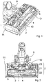
- Fig. 1 shows a perspective partial view of a floor nozzle according to the invention.
- a housing upper part (not shown) of a nozzle body 11 of the floor nozzle is removed so that a view into the interior of the nozzle body 11 is shown.
- the floor nozzle has a one-piece electrical circuit board 1.
- On the one-piece electrical circuit board 1 are - purely by way of example two - light sources (not shown), a component for setting a light source supply voltage, a coolant (not shown) for cooling the two light sources, a contact element (not shown) for connection to a first Connector and a component for smoothing a PWM signal (not shown) arranged.
- the floor nozzle also has a light guide 2, which is connected to the printed circuit board 1, and a reflector 3.
- the floor nozzle furthermore has a joint 9 which has a cable harness (not shown) with a second plug (not shown).
- the floor nozzle has a roller brush 4.
- the brush roller 4 extends along a width b of the floor nozzle, which extends perpendicularly or essentially perpendicularly to the working direction of the floor nozzle.
- the floor nozzle also has a suction channel 10.
- the one-piece printed circuit card is arranged between the joint 9 and the brush roller 4 above the suction channel 10.
- Fig. 2 shows a top view of the in Fig. 1 shown floor nozzle.
- the upper housing part (not shown) has been removed, so that a view into the interior of the nozzle body 11 is shown.
- the light guide 2 is arranged circumferentially around the brush roller 4.
- the light guide 2 has two light coupling points 23, two light insertion areas 22 and one light output area 22.
- the light coupling points 23 are arranged behind the brush roller 4, the light insertion areas 21 are arranged laterally or left and right around the brush roller 4 and the light extraction area 22 is arranged in front of the brush roller 4, based on the working position of the floor nozzle.
- FIG. 13 shows a perspective view of part of the FIG Fig. 1 shown floor nozzle.
- the one-piece printed circuit board 1 and the light guide 2 are shown.
- the light guide 2 is annular with a bending radius r.
- the light guide 2 is arranged on the printed circuit card 1 at the light coupling points 23 and fastened to it.
- FIG. 13 shows an enlarged partial view of the FIG Fig. 3 part of the floor nozzle shown in Fig. 3 marked as IV.
- the floor nozzle has the one-piece printed circuit card 1 with the two light sources 7, to each of which a light coupling point 23 is fastened by means of a centering part 8. Furthermore, the circuit card 1 has two coolants 6 in the form of two cooling surfaces.
Landscapes
- Engineering & Computer Science (AREA)
- Mechanical Engineering (AREA)
- Nozzles For Electric Vacuum Cleaners (AREA)
- Electric Vacuum Cleaner (AREA)
Abstract
Description
- Die Erfindung betrifft eine Bodendüse und einen Staubsauger. Insbesondere betrifft die Erfindung eine Bodendüse mit einer Lichtquelle und einen Staubsauger, der die Bodendüse aufweist.
- Eine Bodendüse, die eine Lichtquelle aufweist, ist aus der
WO 2014/154995A1 bekannt. Die Bodendüse weist einen Körper mit einer Vorderkante, eine Lichtquelle sowie einen Lichtleiter auf. An der Vorderkante ist eine Projektionsfläche angeordnet, die von der Lichtquelle ausgesendetes Licht mittels des Lichtleiters empfängt und auf einen zu reinigenden Untergrund aussendet. - Es besteht aber ein Bedarf an einer montagetechnisch einfachen und wirtschaftlichen Anordnung von Lichtquellen mit allen notwendigen elektronischen Bauteilen innerhalb einer Bodendüse, wobei ein homogenes Leuchtbild erzeugt und der zu reinigende Untergrund vor der Bodendüse gut ausgeleuchtet wird.
- Der Erfindung stellt sich somit das Problem, eine Bodendüse und einen Staubsauger mit einer montagetechnisch einfachen und wirtschaftlichen Anordnung von Lichtquellen mit allen notwendigen elektronischen Bauteilen innerhalb der Bodendüse bereitzustellen. Gleichzeitig soll mittels der Bodendüse ein homogenes Leuchtbild erzeugt werden und der zu reinigende Untergrund vor der Bodendüse gut ausgeleuchtet werden.
- Erfindungsgemäß wird dieses Problem durch eine Bodendüse mit den Merkmalen des Patentanspruchs 1 und einen Staubsauger mit den Merkmalen des Patentanspruchs 12 gelöst. Vorteilhafte Ausgestaltungen und Weiterbildungen der Erfindung ergeben sich aus den nachfolgenden Unteransprüchen.
- Die mit der Erfindung erreichbaren Vorteile bestehen neben dem Erreichen eines homogenen Leuchtbilds in einer relativ einfachen Montage der Bodendüse mit einer relativ geringen Anzahl an Leiterkarten, Kabeln und Bauteilschnittstellen, die zu einander ausgerichteten werden müssen. Damit verbunden sind die Montagekosten relativ gering. Aufgrund der Synergien der Leiterkarte und Schnittstellen, die als Stecker und nicht als Lötverbindungen ausgeführt sind, weist die Bodendüse relativ geringe Materialkosten auf.
- Zudem können relativ leistungsstarke Lichtquellen eingesetzt werden, da ein relativ großer Bauraum für Kühlflächen zu Verfügung steht. Die Leiterkarte ist bevorzugt in der Mitte der Bodendüse montiert und damit weit entfernt und gut geschützt von möglichen mechanischen Belastungen durch Stürze oder Kollisionen mit z.B. Tischbeinen. Dadurch kann eine relativ lange Lebensdauer der Bodendüse erreicht werden. Bei der Montage können die Leiterkarte und der Lichtleiter optimal und toleranzunempfindliche zueinander positioniert und montiert werden, was zu einer gleichbleibenden und relativ hohen Qualität führt.
- Die Erfindung betrifft eine Bodendüse für einen Staubsauger, aufweisend
- eine einstückige Leiterkarte (1), auf der mindestens eine Lichtquelle (7), ein Bauteil zum Einstellen einer Lichtquellen-Versorgungsspannung, ein Kühlmittel (6) zum Kühlen der mindestens einen Lichtquelle (7) und ein Kontaktelement (5) zur Verbindung mit einem elektrischen Leiter angeordnet sind;
- einen Lichtleiter (2), der mit der Leiterkarte (1) verbunden ist und der mindestens eine Lichteinkoppelstelle (23) zum Einkoppeln von der mindestens einen Lichtquelle (7) ausgesendetem Licht, einen Lichtauskoppelbereich (22) zum Auskoppeln des eingekoppelten Lichts auf einen zu reinigenden Untergrund und mindestens einen Lichteinführbereich (21) zum Einführen des Lichts von der mindestens einen Lichteinkoppelstelle (23) in den Lichtauskoppelbereich (22) aufweist; und
- ein Gelenk (9).
- Die Leiterkarte ist einstückig derart ausgebildet, dass alle für eine Beleuchtung erforderlichen Bauteile auf ihr angeordnet sind. Die mindestens eine Lichtquelle ist bevorzugt als LED ausgebildet. LEDs sind relativ kostengünstig und leistungsstark. Das Kühlmittel ist bevorzugt als eine Kühlfläche ausgebildet.
- In einer bevorzugten Ausführungsform weist die Bodendüse weiterhin einen weiteren Kabelbaum auf, der den ersten Stecker, einen dritten Stecker, der zur Verbindung mit dem zweiten Stecker ausgebildet ist, und einen vierten Stecker aufweist, der zur Verbindung mit einem Motor des Staubsaugers ausgebildet ist, mit dem die Bodendüse zu verwenden ist. Durch den weiteren Kabelbaum ist eine einfache Variantenbildung für die Bodendüse mit und ohne Lichtquelle in der Montage umsetzbar. Von der Bodendüse kann es daher eine Variante mit Lichtquelle und eine Variante ohne Lichtquelle geben, ohne dass Änderungen an der Bodendüse vorgenommen werden. Dadurch können weiterhin Kosten eingespart werden. Die jeweiligen Stecker sind bevorzugt jeweils kodiert.
- In einer bevorzugten Ausführungsform ist der Lichtleiter aus Kunststoff ausgebildet. Der Lichtleiter ist bevorzugt das einzige Kunststoffbauteil, was an die einstückige Leiterkarte montiert ist. Somit kann eine optimale, toleranzunempfindliche Einkopplung der mindestens einen Lichtquelle bevorzugt LED in den Lichtleiter umgesetzt werden, ohne dass Abweichungen in anderen Bauteilen zu einem Verschieben vom Lichtquellen-Mittelpunkt und der entsprechenden Lichteinkoppelstelle führen.
- Bevorzugt weist der Lichtleiter benachbart zu der mindestens einen Lichteinkoppelstelle ein Befestigungselement mit einem Zentrierteil auf. Durch dieses Zentrierteil beispielsweise in Form einer oder mehrerer Zentrierrasten kann eine optimale Positionierung des Lichtquellen-Mittelpunktes zu der entsprechenden Lichteinkoppelstelle erreicht werden.
- In einer bevorzugten Ausführungsform weist der Lichtleiter einen Durchmesser im Bereich von 1 bis 5 mm, bevorzugt 3 mm (±2 mm) auf. Dadurch wird eine Unterfahrhöhe nur gering beeinflusst. Die Unterfahrhöhe beträgt bevorzugt ≤65 mm, bevorzugter ≤60 mm. Alternativ oder zusätzlich bevorzugt weist der Lichtleiter einen oder mehrere Biegeradien im Bereich von 7 x Durchmesser > Biegeradius > 3 x Durchmesser auf. Durch derartige Biegeradien können Lichtverluste relativ gering gehalten werden. Bevorzugt ist der Lichtleiter ringförmig ausgebildet, wobei der Ausdruck "ringförmig" nicht kreisförmig bedeutet sondern vielmehr bedeutet, dass keine spitz zulaufenden Ecken vorhanden sind. Bevorzugt weist der Lichtleiter abgerundete Ecken auf. Weiterhin alternativ oder zusätzlich bevorzugt weist der Lichtleiter eine Auskoppellänge im Bereich von 70 bis 90 %, bevorzugt 80% (±10%) einer Düsenbreite auf, wobei die Düsenbreite sich quer zur Arbeitsrichtung der Bodendüse erstreckt.
- Bevorzugt weist die Bodendüse eine Bürstenwalze auf. Dadurch kann eine höhere Reinigungsleistung erreicht werden. Die mindestens eine Lichtquelle ist bevorzugt hinter der Bürstenwalze angeordnet, bezogen auf eine Arbeitsposition der Bodendüse. Durch Anordnung der Lichtquelle hinter die Bürstenwalze ist eine vordere Randabsaugung optimiert. Die vordere Randabsaugung der Bodendüse liegt bevorzugt im Bereich von 15 bis 25 mm, bevorzugt 20 mm oder weniger.
- In einer bevorzugten Ausführungsform ist die einstückige Leiterkarte zwischen dem Gelenk und der Bürstenwalze oberhalb eines Saugkanals angeordnet, bezogen auf die Arbeitsposition der Bodendüse. Dadurch wird relativ wenig Bauraum für die einstückige Leiterkarte benötigt.
- Bevorzugt weist die Bodendüse zwei Lichteinführbereiche auf, die seitlich zu der Bürstenwalze angeordnet sind, und ist der Lichtauskoppelbereich in einem Bereich vor der Bürstenwalze angeordnet, bezogen auf die Arbeitsposition der Bodendüse. Die Lichtführung führt somit links und rechts um die Bürstenwalze herum in den vorderen Bereich der Bodendüse vor die Bürstenwalze, wo der Lichtauskoppelbereich beginnt, bezogen auf die Arbeitsposition der Bodendüse. Dadurch findet weiterhin eine homogene Auskopplung des Lichts zur Ausleuchtung des zu saugenden Untergrunds statt.
- Bevorzugt weist die Bodendüse weiterhin einen Reflektor auf. Dadurch kann weiterhin eine homogene Auskopplung des Lichts zur Ausleuchtung des zu saugenden Untergrunds stattfinden.
- Die Erfindung betrifft ferner einen Staubsauger, der eine Bodendüse nach einer oder mehreren der vorangehend beschriebenen Ausführungsformen aufweist.
- Bevorzugt ist der Staubsauger als ein handgeführter Staubsauger ausgebildet. Unter dem Ausdruck "handgeführt" ist zu verstehen, dass der Staubsauger per Hand von dem Nutzer bei Betrieb geführt wird. Bevorzugter ist der Staubsauger als Stab-Staubsauger ausgebildet, der auch als Stiel-Staubsauger oder Stick-Staubsauger bezeichnet wird.
- Der Staubsauger ist bevorzugt ein Akkustaubsauger. D.h., der Staubsauger weist einen Akkumulator auf und ist ausgelegt, mittels des Akkumulators als Stromquelle betrieben zu werden.
- Bevorzugt weist der Staubsauger weiterhin einen Motor mit einem fünften Stecker auf, wobei der erste Stecker mit dem Kontaktelement zur Verbindung mit dem ersten Stecker verbunden ist, der zweite Stecker mit dem dritten Stecker verbunden ist und der vierte Stecker mit dem fünften Stecker verbunden ist. Durch diese Verbindungsart muss bei der erfindungsgemäßen Bodendüse keine andere Motor- oder Gelenkvariante erzeugt werden als bei einer weiteren Bodendüse ohne Leiterkarte, Lichtquelle, Lichtleiter. Bei der Variante ohne Licht sind der fünfte Stecker und der zweite Stecker verbindbar und/oder verbunden. Im Vergleich zu der weiteren Bodendüse kommen bei der erfindungsgemäßen Bodendüse nur Bauteile hinzu, und die Leiterkarte übernimmt die Aufgabe Strom für den Motor zu leiten. Dies wird mit kostengünstigen Steckern und nicht mit angelöteten Kabeln realisiert. Dem Staubsauger kann neben der erfindungsgemäßen Bodendüse eine weitere Bodendüse ohne Leiterkarte, Lichtquelle und ohne Lichtleiter montiert werden, ohne dass aufwändige Änderungen am Staubsauger oder Anschlussmöglichkeiten der Bodendüsen vorgenommen werden müssten.
- Ein Ausführungsbeispiel der Erfindung ist in den Zeichnungen rein schematisch dargestellt und wird nachfolgend näher beschrieben. Es zeigt
- Fig. 1
- eine perspektivische Teil-Ansicht einer erfindungsgemäßen Bodendüse;
- Fig. 2
- eine Draufsicht auf die in
Fig. 1 gezeigte Bodendüse; - Fig. 3
- eine perspektivische Ansicht auf einen Teil der in
Fig. 1 gezeigten Bodendüse; und - Fig. 4
- eine vergrößerte Teil-Ansicht des in
Fig. 3 gezeigten Teils der Bodendüse. -
Fig. 1 zeigt eine perspektivische Teil-Ansicht einer erfindungsgemäßen Bodendüse. Ein Gehäuse-Oberteil (nicht gezeigt) eines Düsenkörpers 11 der Bodendüse ist entfernt, so dass ein Blick in das Innere des Düsenkörpers 11 gezeigt ist. Die Bodendüse weist eine einstückige elektrische Leiterkarte 1 auf. Auf der einstückigen elektrischen Leiterkarte 1 sind - rein beispielhaft zwei - Lichtquellen (nicht gezeigt), ein Bauteil zum Einstellen einer Lichtquellen-Versorgungsspannung, ein Kühlmittel (nicht gezeigt) zum Kühlen der zwei Lichtquellen, ein Kontaktelement (nicht gezeigt) zur Verbindung mit einem ersten Stecker und ein Bauteil zum Glätten eines PWM-Signals (nicht gezeigt) angeordnet. Die Bodendüse weist ferner einen Lichtleiter 2, der mit der Leiterkarte 1 verbunden ist, sowie einen Reflektor 3 auf. Die Bodendüse weist weiterhin ein Gelenk 9 auf, das einen Kabelbaum (nicht gezeigt) mit einem zweiten Stecker (nicht gezeigt) aufweist. Zudem weist die Bodendüse eine Bürstenwalze 4 auf. Die Bürstenwalze 4 erstreckt sich entlang einer Breite b der Bodendüse, die sich senkrecht oder im Wesentlichen senkrecht zur Arbeitsrichtung der Bodendüse erstreckt. Ferner weist die Bodendüse einen Saugkanal 10 auf. Die einstückige Leiterkarte ist zwischen dem Gelenk 9 und der Bürstenwalze 4 oberhalb des Saugkanals 10 angeordnet. -
Fig. 2 zeigt eine Draufsicht auf die inFig. 1 gezeigte Bodendüse. Das Gehäuse-Oberteil (nicht gezeigt) ist entfernt, so dass ein Blick in das Innere des Düsenkörpers 11 gezeigt ist. Der Lichtleiter 2 ist umlaufend um die Bürstenwalze 4 herum angeordnet. Der Lichtleiter 2 weist zwei Lichteinkoppelstellen 23 auf, zwei Lichteinführbereiche 22 und einen Lichtauskoppelbereich 22 auf. Die Lichteinkoppelstellen 23 sind hinter der Bürstenwalze 4 angeordnet, die Lichteinführbereiche 21 sind seitlich bzw. links und rechts um die Bürstenwalze 4 herum angeordnet und der Lichtauskoppelbereich 22 ist vor der Bürstenwalze 4 angeordnet, bezogen auf die Arbeitsposition der Bodendüse. -
Fig. 3 zeigt eine perspektivische Ansicht auf einen Teil der inFig. 1 gezeigten Bodendüse. Gezeigt sind die einstückige Leiterkarte 1 und der Lichtleiter 2. Der Lichtleiter 2 ist ringförmig mit einem Biegeradius r ausgebildet. An den Lichteinkoppelstellen 23 ist der Lichtleiter 2 an die Leiterkarte 1 angeordnet und an ihr befestigt. -
Fig. 4 zeigt eine vergrößerte Teil-Ansicht des inFig. 3 gezeigten Teils der Bodendüse, die inFig. 3 als IV gekennzeichnet ist. Die Bodendüse weist die einstückige Leiterkarte 1 mit den zwei Lichtquellen 7 auf, an denen jeweils eine Lichteinkoppelstelle 23 mittels jeweils eines Zentrierteils 8 befestigt ist. Ferner weist die Leiterkarte 1 zwei Kühlmittel 6 in Form von zwei Kühlflächen auf. -
- r
- Biegeradius
- b
- Düsenbreite
- 1
- Leiterkarte
- 2
- Lichtkabel
- 21
- Lichteinführbereich
- 22
- Lichtauskoppelbereich
- 23
- Lichteinkoppelstelle
- 3
- Reflektor
- 4
- Bürstenwalze
- 5
- Kontaktelement
- 6
- Kühlmittel
- 7
- Lichtquelle
- 8
- Befestigungselement
- 9
- Gelenk
- 10
- Saugkanal
- 11
- Düsenkörper
Claims (13)
- Bodendüse für einen Staubsauger, aufweisend- eine einstückige Leiterkarte (1), auf der mindestens eine Lichtquelle (7), ein Bauteil zum Einstellen einer Lichtquellen-Versorgungsspannung, ein Kühlmittel (6) zum Kühlen der mindestens einen Lichtquelle (7) und ein Kontaktelement (5) zur Verbindung mit einem elektrischen Leiter angeordnet sind;- einen Lichtleiter (2), der mit der Leiterkarte (1) verbunden ist und der mindestens eine Lichteinkoppelstelle (23) zum Einkoppeln von der mindestens einen Lichtquelle (7) ausgesendetem Licht, einen Lichtauskoppelbereich (22) zum Auskoppeln des eingekoppelten Lichts auf einen zu reinigenden Untergrund und mindestens einen Lichteinführbereich (21) zum Einführen des Lichts von der mindestens einen Lichteinkoppelstelle (23) in den Lichtauskoppelbereich (22) aufweist; und- ein Gelenk (9).
- Bodendüse nach Anspruch 1, dadurch gekennzeichnet, dass das Kontaktelement zur Verbindung mit einem elektrischen Leiter über einen ersten Stecker ausgeführt ist.
- Bodendüse nach Anspruch 1 oder 2, dadurch gekennzeichnet, dass das Gelenk (9) einen Kabelbaum mit einem zweiten Stecker aufweist.
- Bodendüse nach einem der vorangehenden Ansprüche, gekennzeichnet durch einen weiteren Kabelbaum, der den ersten Stecker, einen dritten Stecker, der zur Verbindung mit dem zweiten Stecker ausgebildet ist, und einen vierten Stecker aufweist, der zur Verbindung mit einem Motor des Staubsaugers ausgebildet ist, mit dem die Bodendüse zu verwenden ist.
- Bodendüse nach einem der vorangehenden Ansprüche, dadurch gekennzeichnet, dass der Lichtleiter (2) aus Kunststoff ausgebildet ist.
- Bodendüse nach einem der vorangehenden Ansprüche, dadurch gekennzeichnet, dass der Lichtleiter (2) benachbart zu der mindestens einen Lichteinkoppelstelle (23) ein Befestigungselement (8) mit einem Zentrierteil aufweist.
- Bodendüse nach einem der vorangehenden Ansprüche, dadurch gekennzeichnet, dass der Lichtleiter (2) einen Durchmesser im Bereich von 1 bis 5 mm, einen oder mehrere Biegeradius (r) im Bereich von 7 x Durchmesser > Biegeradius > 3 x Durchmesser und/oder eine Auskoppellänge im Bereich von 7 bis 90 % einer Düsenbreite (b) aufweist, wobei die Düsenbreite (b) sich quer zur Arbeitsrichtung der Bodendüse erstreckt.
- Bodendüse nach einem der vorangehenden Ansprüche, gekennzeichnet durch eine Bürstenwalze (4), wobei bevorzugt die mindestens eine Lichtquelle (7) hinter der Bürstenwalze (4) angeordnet ist, bezogen auf eine Arbeitsposition der Bodendüse.
- Bodendüse nach Anspruch 8, dadurch gekennzeichnet, dass die einstückige Leiterkarte (1) zwischen dem Gelenk (9) und der Bürstenwalze (4) oberhalb eines Saugkanals (10) angeordnet ist, bezogen auf die Arbeitsposition der Bodendüse.
- Bodendüse nach Anspruch 8 oder 9, dadurch gekennzeichnet, dass die Bodendüse zwei Lichteinführbereiche (21) aufweist, die seitlich zu der Bürstenwalze (4) angeordnet sind, und der Lichtauskoppelbereich (22) in einem Bereich vor der Bürstenwalze (4) angeordnet ist, bezogen auf die Arbeitsposition der Bodendüse.
- Bodendüse nach einem der vorangehenden Ansprüche, dadurch gekennzeichnet, dass auf der Leiterkarte (1) ein Bauteil zum Glätten eines PWM-Signals angeordnet ist.
- Staubsauger, aufweisend eine Bodendüse nach einem der vorangehenden Ansprüche.
- Staubsauger nach Anspruch 12, dadurch gekennzeichnet, dass er weiterhin einen Motor mit einem fünften Stecker aufweist, wobei der erste Stecker mit dem Kontaktelement zur Verbindung mit dem ersten Stecker verbunden ist, der zweite Stecker mit dem dritten Stecker verbunden ist und der vierte Stecker mit dem fünften Stecker verbunden ist.
Applications Claiming Priority (1)
| Application Number | Priority Date | Filing Date | Title |
|---|---|---|---|
| DE102019117768.5A DE102019117768A1 (de) | 2019-07-02 | 2019-07-02 | Bodendüse und Staubsauger |
Publications (3)
| Publication Number | Publication Date |
|---|---|
| EP3760093A1 true EP3760093A1 (de) | 2021-01-06 |
| EP3760093C0 EP3760093C0 (de) | 2024-08-07 |
| EP3760093B1 EP3760093B1 (de) | 2024-08-07 |
Family
ID=70977362
Family Applications (1)
| Application Number | Title | Priority Date | Filing Date |
|---|---|---|---|
| EP20177928.7A Active EP3760093B1 (de) | 2019-07-02 | 2020-06-03 | Bodendüse und staubsauger |
Country Status (2)
| Country | Link |
|---|---|
| EP (1) | EP3760093B1 (de) |
| DE (1) | DE102019117768A1 (de) |
Cited By (4)
| Publication number | Priority date | Publication date | Assignee | Title |
|---|---|---|---|---|
| EP4696207A1 (de) | 2024-08-16 | 2026-02-18 | Miele & Cie. KG | Bodeneinheit für ein handgeführtes bodenreinigungsgerät, verfahren zur montage einer solchen bodeneinheit und handgeführtes bodenreinigungsgerät mit einer solchen bodeneinheit |
| EP4696208A1 (de) | 2024-08-16 | 2026-02-18 | Miele & Cie. KG | Bodeneinheit für ein bodenreinigungsgerät und bodenreinigungsgerät |
| BE1032959A1 (de) | 2024-08-19 | 2026-04-22 | Miele & Cie | Bodeneinheit für ein handgeführtes bodenreinigungsgerät, verfahren zur montage einer solchen bodeneinheit und handgeführtes bodenreinigungsgerät mit einer solchen bodeneinheit |
| BE1032960A1 (de) | 2024-08-19 | 2026-04-22 | Miele & Cie | Bodeneinheit für ein bodenreinigungsgerät und bodenreinigungsgerät |
Citations (5)
| Publication number | Priority date | Publication date | Assignee | Title |
|---|---|---|---|---|
| DE102011086968A1 (de) * | 2011-11-23 | 2013-05-23 | BSH Bosch und Siemens Hausgeräte GmbH | Beleuchtungsmodul für ein Hauhaltsgerät |
| WO2014154995A1 (fr) | 2013-03-26 | 2014-10-02 | Seb S.A. | Suceur d'aspirateur comportant une source lumineuse |
| US20150292730A1 (en) * | 2014-04-11 | 2015-10-15 | Ivd Global Corporation | Vacuum Cleaner Inlet Door Lighting Device |
| JP2016028670A (ja) * | 2014-07-23 | 2016-03-03 | パナソニックIpマネジメント株式会社 | 電気掃除機およびその吸込具 |
| KR20170126255A (ko) * | 2016-05-09 | 2017-11-17 | 엘지전자 주식회사 | 진공 청소기 |
-
2019
- 2019-07-02 DE DE102019117768.5A patent/DE102019117768A1/de not_active Ceased
-
2020
- 2020-06-03 EP EP20177928.7A patent/EP3760093B1/de active Active
Patent Citations (5)
| Publication number | Priority date | Publication date | Assignee | Title |
|---|---|---|---|---|
| DE102011086968A1 (de) * | 2011-11-23 | 2013-05-23 | BSH Bosch und Siemens Hausgeräte GmbH | Beleuchtungsmodul für ein Hauhaltsgerät |
| WO2014154995A1 (fr) | 2013-03-26 | 2014-10-02 | Seb S.A. | Suceur d'aspirateur comportant une source lumineuse |
| US20150292730A1 (en) * | 2014-04-11 | 2015-10-15 | Ivd Global Corporation | Vacuum Cleaner Inlet Door Lighting Device |
| JP2016028670A (ja) * | 2014-07-23 | 2016-03-03 | パナソニックIpマネジメント株式会社 | 電気掃除機およびその吸込具 |
| KR20170126255A (ko) * | 2016-05-09 | 2017-11-17 | 엘지전자 주식회사 | 진공 청소기 |
Cited By (4)
| Publication number | Priority date | Publication date | Assignee | Title |
|---|---|---|---|---|
| EP4696207A1 (de) | 2024-08-16 | 2026-02-18 | Miele & Cie. KG | Bodeneinheit für ein handgeführtes bodenreinigungsgerät, verfahren zur montage einer solchen bodeneinheit und handgeführtes bodenreinigungsgerät mit einer solchen bodeneinheit |
| EP4696208A1 (de) | 2024-08-16 | 2026-02-18 | Miele & Cie. KG | Bodeneinheit für ein bodenreinigungsgerät und bodenreinigungsgerät |
| BE1032959A1 (de) | 2024-08-19 | 2026-04-22 | Miele & Cie | Bodeneinheit für ein handgeführtes bodenreinigungsgerät, verfahren zur montage einer solchen bodeneinheit und handgeführtes bodenreinigungsgerät mit einer solchen bodeneinheit |
| BE1032960A1 (de) | 2024-08-19 | 2026-04-22 | Miele & Cie | Bodeneinheit für ein bodenreinigungsgerät und bodenreinigungsgerät |
Also Published As
| Publication number | Publication date |
|---|---|
| EP3760093C0 (de) | 2024-08-07 |
| EP3760093B1 (de) | 2024-08-07 |
| DE102019117768A1 (de) | 2021-01-07 |
Similar Documents
| Publication | Publication Date | Title |
|---|---|---|
| EP3760093B1 (de) | Bodendüse und staubsauger | |
| DE102009005546B4 (de) | Gerät und Verfahren zur Herstellung eines Geräts | |
| EP0862243B1 (de) | HF-Koaxial-Steckverbinder | |
| EP0848459A2 (de) | Leitungs-Steckverbindung | |
| DE102009008095A1 (de) | Konfektionierbares Leuchtband | |
| EP0923172A3 (de) | Anordnung betreffend eine elektrische und/oder elektronische Bauelemente tragende Elektrikplatte mit einem elektrischen Steckverbinder und einer Abdeckung | |
| EP3232751B1 (de) | Elektrische steckkupplungsvorrichtung | |
| DE20315112U1 (de) | Zusammensetzbarer, elektrischer Anschluss | |
| WO2012049117A1 (de) | Beleuchtungseinrichtung | |
| EP3760092A1 (de) | Bodendüse und staubsauger | |
| DE3926802A1 (de) | Elektrischer steckverbinder | |
| DE102008001557A1 (de) | Messerleisten-Kontaktierung über Zwischenleiterplatten | |
| EP3219446A1 (de) | Handgeführtes arbeitsgerät mit einem elektromotor | |
| DE102004014137A1 (de) | Anordnung mit einem Elektromotor und einer Hauptleiterplatte und Montageverfahren | |
| EP2230727A1 (de) | Netzanschlussleitung und Elektrogerät | |
| EP2916393B1 (de) | System mit elektrischen Einheiten | |
| EP1182917B1 (de) | Vorrichtung zur Abschirmung | |
| DE202013105726U1 (de) | Einpoliger elektrischer Verbinder mit hermaphroditischen Kontaktelementen | |
| EP0402739B1 (de) | Einrichtung zum elektrischen Verbinden von einschiebbaren elektrischen Baugruppen | |
| DE19651800B4 (de) | Leitungs-Steckverbindung | |
| EP1168526A2 (de) | Leiterplattensteckverbindung | |
| DE29621580U1 (de) | Leitungs-Steckverbindung | |
| EP3805639B1 (de) | Leuchte mit steckkontakt, verwendung einer solchen leuchte und steckverbinder für eine solche leuchte | |
| DE102013100770A1 (de) | Motorsteuervorrichtung | |
| DE4017752C2 (de) |
Legal Events
| Date | Code | Title | Description |
|---|---|---|---|
| PUAI | Public reference made under article 153(3) epc to a published international application that has entered the european phase |
Free format text: ORIGINAL CODE: 0009012 |
|
| STAA | Information on the status of an ep patent application or granted ep patent |
Free format text: STATUS: REQUEST FOR EXAMINATION WAS MADE |
|
| 17P | Request for examination filed |
Effective date: 20201118 |
|
| AK | Designated contracting states |
Kind code of ref document: A1 Designated state(s): AL AT BE BG CH CY CZ DE DK EE ES FI FR GB GR HR HU IE IS IT LI LT LU LV MC MK MT NL NO PL PT RO RS SE SI SK SM TR |
|
| AX | Request for extension of the european patent |
Extension state: BA ME |
|
| STAA | Information on the status of an ep patent application or granted ep patent |
Free format text: STATUS: EXAMINATION IS IN PROGRESS |
|
| 17Q | First examination report despatched |
Effective date: 20220517 |
|
| GRAP | Despatch of communication of intention to grant a patent |
Free format text: ORIGINAL CODE: EPIDOSNIGR1 |
|
| STAA | Information on the status of an ep patent application or granted ep patent |
Free format text: STATUS: GRANT OF PATENT IS INTENDED |
|
| INTG | Intention to grant announced |
Effective date: 20240208 |
|
| GRAS | Grant fee paid |
Free format text: ORIGINAL CODE: EPIDOSNIGR3 |
|
| GRAA | (expected) grant |
Free format text: ORIGINAL CODE: 0009210 |
|
| STAA | Information on the status of an ep patent application or granted ep patent |
Free format text: STATUS: THE PATENT HAS BEEN GRANTED |
|
| AK | Designated contracting states |
Kind code of ref document: B1 Designated state(s): AL AT BE BG CH CY CZ DE DK EE ES FI FR GB GR HR HU IE IS IT LI LT LU LV MC MK MT NL NO PL PT RO RS SE SI SK SM TR |
|
| REG | Reference to a national code |
Ref country code: GB Ref legal event code: FG4D Free format text: NOT ENGLISH |
|
| REG | Reference to a national code |
Ref country code: CH Ref legal event code: EP |
|
| REG | Reference to a national code |
Ref country code: DE Ref legal event code: R096 Ref document number: 502020008779 Country of ref document: DE |
|
| REG | Reference to a national code |
Ref country code: IE Ref legal event code: FG4D Free format text: LANGUAGE OF EP DOCUMENT: GERMAN |
|
| U01 | Request for unitary effect filed |
Effective date: 20240807 |
|
| U07 | Unitary effect registered |
Designated state(s): AT BE BG DE DK EE FI FR IT LT LU LV MT NL PT SE SI Effective date: 20240814 |
|
| REG | Reference to a national code |
Ref country code: GB Ref legal event code: 746 Effective date: 20241007 |
|
| PG25 | Lapsed in a contracting state [announced via postgrant information from national office to epo] |
Ref country code: NO Free format text: LAPSE BECAUSE OF FAILURE TO SUBMIT A TRANSLATION OF THE DESCRIPTION OR TO PAY THE FEE WITHIN THE PRESCRIBED TIME-LIMIT Effective date: 20241107 |
|
| PG25 | Lapsed in a contracting state [announced via postgrant information from national office to epo] |
Ref country code: GR Free format text: LAPSE BECAUSE OF FAILURE TO SUBMIT A TRANSLATION OF THE DESCRIPTION OR TO PAY THE FEE WITHIN THE PRESCRIBED TIME-LIMIT Effective date: 20241108 Ref country code: PL Free format text: LAPSE BECAUSE OF FAILURE TO SUBMIT A TRANSLATION OF THE DESCRIPTION OR TO PAY THE FEE WITHIN THE PRESCRIBED TIME-LIMIT Effective date: 20240807 |
|
| PG25 | Lapsed in a contracting state [announced via postgrant information from national office to epo] |
Ref country code: IS Free format text: LAPSE BECAUSE OF FAILURE TO SUBMIT A TRANSLATION OF THE DESCRIPTION OR TO PAY THE FEE WITHIN THE PRESCRIBED TIME-LIMIT Effective date: 20241207 |
|
| PG25 | Lapsed in a contracting state [announced via postgrant information from national office to epo] |
Ref country code: HR Free format text: LAPSE BECAUSE OF FAILURE TO SUBMIT A TRANSLATION OF THE DESCRIPTION OR TO PAY THE FEE WITHIN THE PRESCRIBED TIME-LIMIT Effective date: 20240807 |
|
| PG25 | Lapsed in a contracting state [announced via postgrant information from national office to epo] |
Ref country code: ES Free format text: LAPSE BECAUSE OF FAILURE TO SUBMIT A TRANSLATION OF THE DESCRIPTION OR TO PAY THE FEE WITHIN THE PRESCRIBED TIME-LIMIT Effective date: 20240807 Ref country code: RS Free format text: LAPSE BECAUSE OF FAILURE TO SUBMIT A TRANSLATION OF THE DESCRIPTION OR TO PAY THE FEE WITHIN THE PRESCRIBED TIME-LIMIT Effective date: 20241107 |
|
| PG25 | Lapsed in a contracting state [announced via postgrant information from national office to epo] |
Ref country code: RS Free format text: LAPSE BECAUSE OF FAILURE TO SUBMIT A TRANSLATION OF THE DESCRIPTION OR TO PAY THE FEE WITHIN THE PRESCRIBED TIME-LIMIT Effective date: 20241107 Ref country code: PL Free format text: LAPSE BECAUSE OF FAILURE TO SUBMIT A TRANSLATION OF THE DESCRIPTION OR TO PAY THE FEE WITHIN THE PRESCRIBED TIME-LIMIT Effective date: 20240807 Ref country code: NO Free format text: LAPSE BECAUSE OF FAILURE TO SUBMIT A TRANSLATION OF THE DESCRIPTION OR TO PAY THE FEE WITHIN THE PRESCRIBED TIME-LIMIT Effective date: 20241107 Ref country code: IS Free format text: LAPSE BECAUSE OF FAILURE TO SUBMIT A TRANSLATION OF THE DESCRIPTION OR TO PAY THE FEE WITHIN THE PRESCRIBED TIME-LIMIT Effective date: 20241207 Ref country code: HR Free format text: LAPSE BECAUSE OF FAILURE TO SUBMIT A TRANSLATION OF THE DESCRIPTION OR TO PAY THE FEE WITHIN THE PRESCRIBED TIME-LIMIT Effective date: 20240807 Ref country code: GR Free format text: LAPSE BECAUSE OF FAILURE TO SUBMIT A TRANSLATION OF THE DESCRIPTION OR TO PAY THE FEE WITHIN THE PRESCRIBED TIME-LIMIT Effective date: 20241108 Ref country code: ES Free format text: LAPSE BECAUSE OF FAILURE TO SUBMIT A TRANSLATION OF THE DESCRIPTION OR TO PAY THE FEE WITHIN THE PRESCRIBED TIME-LIMIT Effective date: 20240807 |
|
| PG25 | Lapsed in a contracting state [announced via postgrant information from national office to epo] |
Ref country code: SM Free format text: LAPSE BECAUSE OF FAILURE TO SUBMIT A TRANSLATION OF THE DESCRIPTION OR TO PAY THE FEE WITHIN THE PRESCRIBED TIME-LIMIT Effective date: 20240807 |
|
| PG25 | Lapsed in a contracting state [announced via postgrant information from national office to epo] |
Ref country code: CZ Free format text: LAPSE BECAUSE OF FAILURE TO SUBMIT A TRANSLATION OF THE DESCRIPTION OR TO PAY THE FEE WITHIN THE PRESCRIBED TIME-LIMIT Effective date: 20240807 |
|
| PG25 | Lapsed in a contracting state [announced via postgrant information from national office to epo] |
Ref country code: SK Free format text: LAPSE BECAUSE OF FAILURE TO SUBMIT A TRANSLATION OF THE DESCRIPTION OR TO PAY THE FEE WITHIN THE PRESCRIBED TIME-LIMIT Effective date: 20240807 |
|
| PLBE | No opposition filed within time limit |
Free format text: ORIGINAL CODE: 0009261 |
|
| STAA | Information on the status of an ep patent application or granted ep patent |
Free format text: STATUS: NO OPPOSITION FILED WITHIN TIME LIMIT |
|
| 26N | No opposition filed |
Effective date: 20250508 |
|
| U20 | Renewal fee for the european patent with unitary effect paid |
Year of fee payment: 6 Effective date: 20250630 |
|
| REG | Reference to a national code |
Ref country code: CH Ref legal event code: H13 Free format text: ST27 STATUS EVENT CODE: U-0-0-H10-H13 (AS PROVIDED BY THE NATIONAL OFFICE) Effective date: 20260127 |
|
| PG25 | Lapsed in a contracting state [announced via postgrant information from national office to epo] |
Ref country code: MC Free format text: LAPSE BECAUSE OF FAILURE TO SUBMIT A TRANSLATION OF THE DESCRIPTION OR TO PAY THE FEE WITHIN THE PRESCRIBED TIME-LIMIT Effective date: 20240807 |
|
| PG25 | Lapsed in a contracting state [announced via postgrant information from national office to epo] |
Ref country code: IE Free format text: LAPSE BECAUSE OF NON-PAYMENT OF DUE FEES Effective date: 20250603 |
|
| PG25 | Lapsed in a contracting state [announced via postgrant information from national office to epo] |
Ref country code: RO Free format text: LAPSE BECAUSE OF FAILURE TO SUBMIT A TRANSLATION OF THE DESCRIPTION OR TO PAY THE FEE WITHIN THE PRESCRIBED TIME-LIMIT Effective date: 20240807 |
|
| PG25 | Lapsed in a contracting state [announced via postgrant information from national office to epo] |
Ref country code: CH Free format text: LAPSE BECAUSE OF NON-PAYMENT OF DUE FEES Effective date: 20250630 |
|
| PGFP | Annual fee paid to national office [announced via postgrant information from national office to epo] |
Ref country code: GB Payment date: 20260622 Year of fee payment: 7 |
|
| PGFP | Annual fee paid to national office [announced via postgrant information from national office to epo] |
Ref country code: TR Payment date: 20260521 Year of fee payment: 7 |
|
| U20 | Renewal fee for the european patent with unitary effect paid |
Year of fee payment: 7 Effective date: 20260630 |
|
| PG25 | Lapsed in a contracting state [announced via postgrant information from national office to epo] |
Ref country code: CY Free format text: LAPSE BECAUSE OF FAILURE TO SUBMIT A TRANSLATION OF THE DESCRIPTION OR TO PAY THE FEE WITHIN THE PRESCRIBED TIME-LIMIT Effective date: 20240807 |