EP3760092B1 - Bodendüse und staubsauger - Google Patents
Bodendüse und staubsauger Download PDFInfo
- Publication number
- EP3760092B1 EP3760092B1 EP20177924.6A EP20177924A EP3760092B1 EP 3760092 B1 EP3760092 B1 EP 3760092B1 EP 20177924 A EP20177924 A EP 20177924A EP 3760092 B1 EP3760092 B1 EP 3760092B1
- Authority
- EP
- European Patent Office
- Prior art keywords
- light
- floor nozzle
- floor
- light guide
- reflector
- Prior art date
- Legal status (The legal status is an assumption and is not a legal conclusion. Google has not performed a legal analysis and makes no representation as to the accuracy of the status listed.)
- Active
Links
Images

Classifications
-
- A—HUMAN NECESSITIES
- A47—FURNITURE; DOMESTIC ARTICLES OR APPLIANCES; COFFEE MILLS; SPICE MILLS; SUCTION CLEANERS IN GENERAL
- A47L—DOMESTIC WASHING OR CLEANING; SUCTION CLEANERS IN GENERAL
- A47L9/00—Details or accessories of suction cleaners, e.g. mechanical means for controlling the suction or for effecting pulsating action; Storing devices specially adapted to suction cleaners or parts thereof; Carrying-vehicles specially adapted for suction cleaners
- A47L9/28—Installation of the electric equipment, e.g. adaptation or attachment to the suction cleaner; Controlling suction cleaners by electric means
- A47L9/30—Arrangement of illuminating devices
-
- F—MECHANICAL ENGINEERING; LIGHTING; HEATING; WEAPONS; BLASTING
- F21—LIGHTING
- F21V—FUNCTIONAL FEATURES OR DETAILS OF LIGHTING DEVICES OR SYSTEMS THEREOF; STRUCTURAL COMBINATIONS OF LIGHTING DEVICES WITH OTHER ARTICLES, NOT OTHERWISE PROVIDED FOR
- F21V33/00—Structural combinations of lighting devices with other articles, not otherwise provided for
- F21V33/0004—Personal or domestic articles
- F21V33/0044—Household appliances, e.g. washing machines or vacuum cleaners
-
- F—MECHANICAL ENGINEERING; LIGHTING; HEATING; WEAPONS; BLASTING
- F21—LIGHTING
- F21Y—INDEXING SCHEME ASSOCIATED WITH SUBCLASSES F21K, F21L, F21S and F21V, RELATING TO THE FORM OR THE KIND OF THE LIGHT SOURCES OR OF THE COLOUR OF THE LIGHT EMITTED
- F21Y2115/00—Light-generating elements of semiconductor light sources
- F21Y2115/10—Light-emitting diodes [LED]
-
- G—PHYSICS
- G02—OPTICS
- G02B—OPTICAL ELEMENTS, SYSTEMS OR APPARATUS
- G02B6/00—Light guides; Structural details of arrangements comprising light guides and other optical elements, e.g. couplings
- G02B6/0001—Light guides; Structural details of arrangements comprising light guides and other optical elements, e.g. couplings specially adapted for lighting devices or systems
- G02B6/0005—Light guides; Structural details of arrangements comprising light guides and other optical elements, e.g. couplings specially adapted for lighting devices or systems the light guides being of the fibre type
- G02B6/001—Light guides; Structural details of arrangements comprising light guides and other optical elements, e.g. couplings specially adapted for lighting devices or systems the light guides being of the fibre type the light being emitted along at least a portion of the lateral surface of the fibre
Definitions
- the invention relates to a floor nozzle and a vacuum cleaner.
- the invention relates to a floor nozzle with a light source and a vacuum cleaner that has the floor nozzle.
- a floor nozzle that has a light source is from WO 2014/154995A1 known.
- the floor nozzle has a body with a front edge, a light source and a light guide. Position and direction information relates to a working position of the floor nozzle.
- a projection surface is arranged on the front edge, which receives light emitted by the light source by means of the light guide and emits it onto a substrate to be cleaned.
- a reflector which is a flat plate, is arranged behind the light guide. As a result, it can only reflect the light that is coupled out to the rear by the light guide. The light that is coupled out upwards or downwards is not reflected and is absorbed by an interior space of the floor nozzle and is thus lost unused as light output.
- the EP 0 530 026 A1 discloses a floor nozzle with a light bulb, which emits light via a light guide with a light decoupling area along the front edge of the floor nozzle.
- the light guide has prismatic recesses in the light decoupling area.
- the JP 2016 093 477 A discloses a floor nozzle with a light source which emits light by means of a light guide along a front edge of the floor nozzle.
- the light guide has prismatic recesses in the light decoupling area.
- the reflector Due to the fact that the reflector is located behind the light guide, scattered light that scatters into the floor nozzle can lead to unwanted light escaping elsewhere. As a result, the floor nozzle shines from an opening other than an actual light area, resulting in an inferior appearance of the floor nozzle. In addition, the light can be emitted forwards in an uncontrolled manner without the light being aimed at the ground in a targeted manner. As a result, a lot of light output is lost in the distance without the user seeing anything of it.
- the invention therefore faces the problem of providing a floor nozzle and a vacuum cleaner which produce a homogeneous light pattern during operation, achieve maximum utilization of the light output and prevent unwanted light coupling.
- the advantages that can be achieved with the invention consist, in addition to a relatively homogeneous light pattern, in the fact that a homogeneous illumination of the subsurface to be vacuumed is achieved without over-illuminated and under-illuminated areas.
- the light guide has small prismatic recesses in the light decoupling area, at which the light from the light guide is deflected forward and emitted from a front light guide surface.
- Information on position and direction relates to a working position and/or working direction of the floor nozzle.
- the light source is preferably designed as one or more LEDs (light emitting diodes). LEDs are inexpensive and powerful.
- the floor nozzle also has a reflector which is arranged in a semicircular or substantially semicircular manner around the light coupling-out area.
- a reflector which is arranged in a semicircular or substantially semicircular manner around the light coupling-out area.
- the reflector preferably has a prism structure on a surface opposite the prismatic recesses. That is, the prismatic structure of the reflector and the prismatic structures of the light guide point to one another arranged.
- the prism structure also ensures a further homogenization of the appearance.
- the light which is not deflected forwards by the prismatic structures of the light guide but is emitted backwards, is optimally received by the reflector and reflected either directly or through a second deflection on the prism structure.
- the floor nozzle also has a lens, which is arranged between the light guide and the floor to be cleaned, based on a working position of the floor nozzle.
- the lens focuses the light on the surface to be vacuumed so that the user sees a brighter illumination of the floor. Furthermore, less light output is lost in the distance.
- the lens is preferably designed as a Fresnel lens. This is relatively inexpensive and requires little use of materials.
- the lens is formed and/or integrated in an upper part of the housing of the floor nozzle.
- the upper part of the housing preferably has a viewing window into which the lens is integrated. This configuration is inexpensive.
- the prismatic recesses each have a height that increases from the outside inwards along a nozzle width, which is arranged transversely, preferably perpendicularly, to the working direction of the floor nozzle.
- a uniform decoupling over the nozzle width can continue to be achieved.
- the floor nozzle preferably has a one-piece circuit board on which at least one light source, a component for setting a light source supply voltage, a coolant for cooling the at least one light source, a contact element for connection to a first plug and a component for smoothing a PWM signal are arranged.
- the at least one light source is preferably designed as an LED. LEDs are relatively inexpensive and powerful.
- the coolant is preferably designed as a cooling surface.
- the light guide is preferably connected to the circuit board.
- the light guide has at least one light coupling point for coupling in light emitted by the at least one light source, the light coupling-out area for coupling out the coupled-in light onto a substrate to be cleaned, and at least one light introduction area for introducing the light from the at least one light coupling point into the light coupling-out area.
- the light guide is made of plastic.
- the light guide is preferably the only plastic component that is mounted on the one-piece circuit board.
- the light guide preferably has a fastening element with a centering part adjacent to the at least one light coupling point.
- This centering part for example in the form of one or more centering detents, enables the center point of the light source to be optimally positioned relative to the corresponding light coupling point.
- the light guide has a diameter in the range from 1 to 5 mm, preferably 3 mm ( ⁇ 2 mm). As a result, the ground clearance is only slightly affected.
- the ground clearance is preferably ⁇ 65 mm, more preferably ⁇ 60 mm.
- the light guide has a bending radius in the range of 7 ⁇ diameter>bending radius>3 ⁇ diameter. Such bending radii allow light losses to be kept relatively low.
- the light guide has a decoupling length in the range of 70 to 90%, preferably 80% ( ⁇ 10%) of a nozzle width, the nozzle width extending transversely to the working direction of the floor nozzle.
- the floor nozzle preferably has a brush roller.
- the at least one light source is preferably arranged behind the brush roller, based on a working position of the floor nozzle. By arranging the light source behind the brush roller, suction at the front edge is optimized.
- the front edge suction of the floor nozzle is preferably in the range from 15 to 25 mm, preferably 20 mm or less.
- the one-piece printed circuit board is arranged between the joint and the brush roller above a suction channel, based on the working position of the floor nozzle. As a result, relatively little installation space is required for the one-piece printed circuit board.
- the floor nozzle preferably has two light introduction areas, which are arranged laterally to the brush roller, and the light decoupling area is arranged in an area in front of the brush roller, relative to the working position of the floor nozzle.
- the light guide thus leads left and right around the brush roller into the front area of the floor nozzle in front of the brush roller, where the light decoupling area begins, based on the working position of the floor nozzle.
- the light guide is made of PMMA.
- the light guide with a transmittance of >91%/5mm is preferred >95%/5mm, more preferably >98%/5mm, measured according to ISO 13468-2.
- a high efficiency of the light output can be achieved even with a long optical fiber path.
- the reflector is preferably made of a white, light gray or silver material. As a result, it is made of a relatively well reflective material.
- the invention also relates to a vacuum cleaner which has a floor nozzle according to one or more of the embodiments described above.
- the vacuum cleaner is preferably designed as a hand-held vacuum cleaner.
- the term "hand-held” means that the vacuum cleaner is operated manually by the user.
- the vacuum cleaner is preferably designed as a stick vacuum cleaner, which is also referred to as a stick vacuum cleaner or stick vacuum cleaner.
- the vacuum cleaner is preferably a cordless vacuum cleaner. That is, the vacuum cleaner has an accumulator and is designed to be operated using the accumulator as a power source.
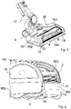
- the floor nozzle has a nozzle body 16, on which an upper housing part 161 with a viewing window 163, a lower housing part 162 and a front flank 164 has.
- a brush roller 4 is arranged inside the nozzle body 16 .
- Inside the nozzle body 16 there is also a suction channel 10 into which solid and/or liquid particles are sucked from the substrate to be vacuumed (not shown) during operation of a vacuum cleaner (not shown) which has the floor nozzle.
- the floor nozzle also has a joint 9 by means of which a suction pipe connection 17 of the floor nozzle can be pivoted and/or tilted.
- the floor nozzle has wheels 18, by means of which it can be moved over the surface to be vacuumed.
- the floor nozzle has a nozzle width b, which extends transversely, in particular perpendicularly, to the working direction of the floor nozzle.
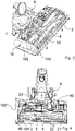
- FIG 2 shows a perspective partial view of FIG 1 shown floor nozzle.
- the floor nozzle has a lens 11 which is integrated into the viewing window 163 .
- the floor nozzle also has a light guide 2 which is visible through the viewing window 163 .
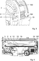
- FIG 3 shows a further perspective partial view of FIG 1 shown floor nozzle.
- the housing top (not shown) has been removed so that a view inside the housing base 162 is shown.
- the floor nozzle has a one-piece electrical circuit board 1 .
- On the one-piece electrical circuit board 1 are - purely by way of example two - light sources (not shown), a component for setting a light source supply voltage, a coolant (not shown) for cooling the two light sources, a contact element (not shown) for connection to a first Connector and a component for smoothing a PWM signal (not shown) arranged.
- the circuit board 1 is arranged between the joint 9 and the brush roller 4 above the suction channel 10, based on the working position of the floor nozzle.
- the floor nozzle also has a light guide 2 which is connected to the printed circuit board 1 and a reflector 3 .
- the light guide 2 is designed to couple in light emitted by the light sources and to couple out it onto a substrate (not shown) to be vacuumed.
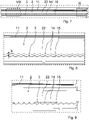
- the light guide 2 is arranged circumferentially around the brush roller 4 .
- the light guide 2 has two light in-coupling points 23 , two light-introduction areas 21 and a light out-coupling area 22 .
- the light coupling points 23 are arranged behind the brush roller 4, the light introduction areas 21 are arranged to the side or left and right around the brush roller 4 and the light decoupling area is arranged in front of the brush roller 4, based on the working position of the floor nozzle.
- the reflector 3 is arranged adjacent to the light guide 2 .
- figure 5 shows a partial cross-sectional view of the 1 shown floor nozzle.
- the reflector 3 is arranged in a semicircle around the light guide 2 .
- the lens 11 is formed in the viewing window 163 in front of the light guide 2 .
- FIG. 6 shows another partial plan view of in 1 shown floor nozzle.
- the housing top (not shown) has been removed so that a view inside the housing base 162 is shown.
- the printed circuit board is omitted for the sake of clarity.
- the light guide 2 is led around the brush roller 4.
- the reflector 3 is arranged between the light decoupling area 22 and the brush roller 4 .
- the light guide 2 is arranged between the housing body 16 and the reflector 3 .
- the light guide 2 in particular the light decoupling region 22 , is arranged between the lens 11 and the reflector 3 .
- the light decoupling area 22 has prismatic recesses 14 , while the reflector 3 has a prism structure 15 .
- Figures 8 and 9 each show an enlarged partial view of the in 7 shown floor nozzle, which in 7 identified as VIII and IX, respectively.
- the prismatic recesses 14 have a height h that increases from outside to inside along the nozzle width (not shown), as can be seen from a comparison of FIGS Figures 8 and 9 is evident. 9 shows compared to 8 an outer area.
- the light guide 2 is ring-shaped with bending radii r. At the light coupling points 23, the light guide 2 is arranged on the printed circuit board 1 and fastened to it.
- FIG. 11 shows an enlarged partial view of the in 10 shown part of the floor nozzle, which in 10 marked as IX.
- the floor nozzle has the printed circuit board 1 with the two light sources 7, on each of which a light coupling point 23 is fastened by means of a centering part 8 in each case. Furthermore, the printed circuit board 1 has two coolants 6 in the form of a cooling surface.
Landscapes
- Engineering & Computer Science (AREA)
- General Engineering & Computer Science (AREA)
- Mechanical Engineering (AREA)
- Nozzles For Electric Vacuum Cleaners (AREA)
- Electric Vacuum Cleaner (AREA)
Description
- Die Erfindung betrifft eine Bodendüse und einen Staubsauger. Insbesondere betrifft die Erfindung eine Bodendüse mit einer Lichtquelle und einen Staubsauger, der die Bodendüse aufweist.
- Eine Bodendüse, die eine Lichtquelle aufweist, ist aus der
WO 2014/154995A1 bekannt. Die Bodendüse weist einen Körper mit einer Vorderkante, eine Lichtquelle sowie einen Lichtleiter auf. Positions- und Richtungsangaben beziehen sich auf eine Arbeitsposition der Bodendüse. An der Vorderkante ist eine Projektionsfläche angeordnet, die von der Lichtquelle ausgesendetes Licht mittels des Lichtleiters empfängt und auf einen zu reinigenden Untergrund aussendet. Hinter dem Lichtleiter ist ein Reflektor angeordnet, der eine flache Platte darstellt. Dadurch kann er nur das Licht reflektieren, das vom Lichtleiter nach hinten ausgekoppelt wird. Las Licht, das nach oben oder unten ausgekoppelt wird, wird nicht reflektiert und wird von einem Innenraum der Bodendüse absorbiert und geht somit als Lichtleistung ungenutzt verloren. - Die
EP 0 530 026 A1 offenbart eine Bodendüse mit einer Glühbirne, welche über einen Lichtleiter mit einem Lichtauskoppelbereich entlang der Vorderkante der Bodendüse Licht aussendet. Der Lichtleiter weist am Lichtauskoppelbereich prismatische Ausnehmungen auf. DieJP 2016 093 477 A - Aufgrund der Tatsache, dass der Reflektor hinter dem Lichtleiter sitzt, kann weiterhin Streulicht, das in die Bodendüse hineinstreut, an anderer Stelle zu ungewolltem Lichtaustritt führen. Dies hat zur Folge, dass die Bodendüse aus einer anderen Öffnung als durch einen eigentlichen Lichtbereich leuchtet, was zu einer geringwertigen Erscheinung der Bodendüse führt. Zudem kann das Licht unkontrolliert nach vorne emittiert werden, ohne dass das Licht zielgerichtet auf den Boden gerichtet wird. Somit geht viel Lichtleistung in der Ferne verloren, ohne dass der Benutzer davon etwas sieht.
- Der Erfindung stellt sich somit das Problem, eine Bodendüse und einen Staubsauger bereitzustellen, die bei Betrieb ein homogenes Lichtbild erzeugen, eine maximale Ausnutzung der Lichtleistung erreichen und eine ungewollte Lichtauskopplung unterbinden.
- Erfindungsgemäß wird dieses Problem durch eine Bodendüse mit den Merkmalen des Patentanspruchs 1 und einen Staubsauger mit den Merkmalen des Patentanspruchs 10 gelöst. Vorteilhafte Ausgestaltungen und Weiterbildungen der Erfindung ergeben sich aus den nachfolgenden Unteransprüchen.
- Die mit der Erfindung erreichbaren Vorteile bestehen neben einem relativ homogenen Leuchtbild darin, dass eine homogene Ausleuchtung des zu saugenden Untergrunds ohne überbeleuchtete und unterbeleuchtete Flächen erreicht wird.
- Die Erfindung betrifft eine Bodendüse, aufweisend
- einen Düsenkörper mit einer Vorderkante;
- eine Lichtquelle, die ausgebildet ist, Licht auszusenden; und
- einen Lichtleiter mit einem Lichtauskoppelbereich, der entlang der Vorderkante angeordnet ist und der ausgebildet ist, von der Lichtquelle ausgesendetes Licht zu empfangen und auf einen zu reinigenden Boden auszusenden, und der prismatische Ausnehmungen aufweist.
- Der Lichtleiter weist im Lichtauskoppelbereich kleine prismatische Ausnehmungen auf, an denen das Licht aus dem Lichtleiter nach vorne umgelenkt und aus einer vorderen Lichtleiterfläche emittiert wird. Positions- und Richtungsangaben beziehen sich auf eine Arbeitsposition und/oder Arbeitsrichtung der Bodendüse.
- Die Lichtquelle ist bevorzugt als eine oder mehrere LEDs (Leuchtdioden) ausgebildet. LEDs sind kostengünstig und leistungsstark.
- In einer bevorzugten Ausführungsform weist die Bodendüse weiterhin einen Reflektor auf, der um den Lichtauskoppelbereich herum halbkreisförmig oder im Wesentlichen halbkreisförmig angeordnet ist. Dadurch wird auch Licht, das unkontrolliert aus dem Lichtleiter ausgekoppelt wird, nach vorne reflektiert. Dies führt weiterhin zu einem optimierten Wirkungsgrad. Durch die mehreren Umlenkungen von der Lichteinkoppelstelle an der Lichtquelle bzw. den LEDs bis in den vorderen Bereich zur Auskoppelung ist das Licht im Lichtleiter nicht optimal gleichgerichtet und kann auch an anderer Stelle als an der prismatischen Struktur auskoppeln. All dieses unkontrolliert ausgekoppelte Licht wird von der halbkreisförmigen Struktur des Reflektors aufgefangen und nach vorne reflektiert. Dadurch wird weiterhin eine optimale Ausbeute der Lichtleistung erzielt.
- Bevorzugt weist der Reflektor auf einer den prismatischen Ausnehmungen gegenüberliegenden Fläche eine Prismenstruktur auf. D.h., die Prismenstruktur des Reflektors und die prismatischen Strukturen des Lichtleiters sind zueinander hinweisend angeordnet. Die Prismenstruktur sorgt weiterhin für eine weitere Homogenisierung des Erscheinungsbildes. So wird das Licht, welches von den prismatischen Strukturen des Lichtleiters nicht nach vorne umgelenkt sondern nach hinten emittiert wird, optimal vom Reflektor aufgenommen und entweder direkt oder durch eine zweite Umlenkung an der Prismenstruktur reflektiert.
- In einer bevorzugten Ausführungsform weist die Bodendüse weiterhin eine Linse auf, die zwischen dem Lichtleiter und dem zu reinigenden Boden angeordnet ist, bezogen auf eine Arbeitsposition der Bodendüse. Durch die Linse wird das Licht gezielt auf den zu saugenden Untergrund fokussiert, so dass der Benutzer eine hellere Ausleuchtung des Fußbodens wahrnimmt. Es geht weiterhin weniger Lichtleistung in der Ferne verloren.
- Bevorzugt ist die Linse als eine Fresnellinse ausgebildet. Diese ist relativ kostengünstig und verlangt wenig Materialeinsatz.
- In einer bevorzugten Ausführungsform ist die Linse in einem Gehäuse-Oberteil der Bodendüse ausgebildet und/oder integriert. Das Gehäuse-Oberteil weist bevorzugt ein Sichtfenster auf, in das die Linse integriert ist. Diese Ausgestaltung ist kostengünstig.
- Bevorzugt weisen die prismatischen Ausnehmungen jeweils eine Höhe auf, die von außen nach innen entlang einer Düsenbreite zunimmt, die quer bevorzugt senkrecht zur Arbeitsrichtung der Bodendüse angeordnet ist. Dadurch kann weiterhin eine gleichmäßige Auskopplung über die Düsenbreite erreicht werden.
- Bevorzugt weist die Bodendüse eine einstückige Leiterkarte auf, auf der mindestens eine Lichtquelle, ein Bauteil zum Einstellen einer Lichtquellen-Versorgungsspannung, ein Kühlmittel zum Kühlen der mindestens einen Lichtquelle, ein Kontaktelement zur Verbindung mit einem ersten Stecker und ein Bauteil zum Glätten eines PWM-Signals angeordnet sind. Die mindestens eine Lichtquelle ist bevorzugt als LED ausgebildet. LEDs sind relativ kostengünstig und leistungsstark. Das Kühlmittel ist bevorzugt als eine Kühlfläche ausgebildet.
- Der Lichtleiter ist bevorzugt mit der Leiterkarte verbunden. Der Lichtleiter weist mindestens eine Lichteinkoppelstelle zum Einkoppeln von von der mindestens einen Lichtquelle ausgesendetem Licht, den Lichtauskoppelbereich zum Auskoppeln des eingekoppelten Lichts auf einen zu reinigenden Untergrund und mindestens einen Lichteinführbereich zum Einführen des Lichts von der mindestens einen Lichteinkoppelstelle in den Lichtauskoppelbereich auf. In einer bevorzugten Ausführungsform ist der Lichtleiter aus Kunststoff ausgebildet. Der Lichtleiter ist bevorzugt das einzige Kunststoffbauteil, was an die einstückige Leiterkarte montiert ist. Somit kann eine optimale, toleranzunempfindliche Einkopplung der mindestens einen Lichtquelle bevorzugt LED in den Lichtleiter umgesetzt werden, ohne dass Abweichungen in anderen Bauteilen zu einem Verschieben vom Lichtquellen-Mittelpunkt und der entsprechenden Lichteinkoppelstelle führen. Bevorzugt weist der Lichtleiter benachbart zu der mindestens einen Lichteinkoppelstelle ein Befestigungselement mit einem Zentrierteil auf. Durch dieses Zentrierteil beispielsweise in Form einer oder mehrerer Zentrierrasten kann eine optimale Positionierung des Lichtquellen-Mittelpunktes zu der entsprechenden Lichteinkoppelstelle erreicht werden.
- In einer bevorzugten Ausführungsform weist der Lichtleiter einen Durchmesser im Bereich von 1 bis 5 mm, bevorzugt 3 mm (±2 mm) auf. Dadurch wird eine Unterfahrhöhe nur gering beeinflusst. Die Unterfahrhöhe beträgt bevorzugt ≤65 mm, bevorzugter ≤60 mm. Alternativ oder zusätzlich bevorzugt weist der Lichtleiter einen Biegeradius im Bereich von 7 x Durchmesser > Biegeradius > 3 x Durchmesser auf. Durch derartige Biegeradien können Lichtverluste relativ gering gehalten werden. Weiterhin alternativ oder zusätzlich bevorzugt weist der Lichtleiter eine Auskoppellänge im Bereich von 70 bis 90 %, bevorzugt 80% (±10%) einer Düsenbreite auf, wobei die Düsenbreite sich quer zur Arbeitsrichtung der Bodendüse erstreckt.
- Bevorzugt weist die Bodendüse eine Bürstenwalze auf. Dadurch kann eine höhere Reinigungsleistung erreicht werden. Die mindestens eine Lichtquelle ist bevorzugt hinter der Bürstenwalze angeordnet, bezogen auf eine Arbeitsposition der Bodendüse. Durch Anordnung der Lichtquelle hinter die Bürstenwalze ist eine vordere Randabsaugung optimiert. Die vordere Randabsaugung der Bodendüse liegt bevorzugt im Bereich von 15 bis 25 mm, bevorzugt 20 mm oder weniger.
- In einer bevorzugten Ausführungsform ist die einstückige Leiterkarte zwischen dem Gelenk und der Bürstenwalze oberhalb eines Saugkanals angeordnet, bezogen auf die Arbeitsposition der Bodendüse. Dadurch wird relativ wenig Bauraum für die einstückige Leiterkarte benötigt.
- Bevorzugt weist die Bodendüse zwei Lichteinführbereiche auf, die seitlich zu der Bürstenwalze angeordnet sind, und ist der Lichtauskoppelbereich in einem Bereich vor der Bürstenwalze angeordnet, bezogen auf die Arbeitsposition der Bodendüse. Die Lichtführung führt somit links und rechts um die Bürstenwalze herum in den vorderen Bereich der Bodendüse vor die Bürstenwalze, wo der Lichtauskoppelbereich beginnt, bezogen auf die Arbeitsposition der Bodendüse. Dadurch findet weiterhin eine homogene Auskopplung des Lichts zur Ausleuchtung des zu saugenden Untergrunds statt.
- In einer bevorzugten Ausführungsform ist der Lichtleiter aus PMMA ausgebildet. Alternativ oder zusätzlich ist der Lichtleiter mit einem Transmissionsgrad von >91 %/5mm, bevorzugt >95%/5mm, bevorzugter >98%/5mm ausgebildet, gemessen nach ISO 13468-2. Dadurch kann auch bei einem langen Lichtleiterweg ein hoher Wirkungsgrad der Lichtleistung zu erzielen.
- Bevorzugt ist der Reflektor aus einem weißen, hellgrauen oder silbernen Material ausgebildet. Dadurch ist er aus einem relativ gut reflektierenden Material gefertigt.
- Die Erfindung betrifft ferner einen Staubsauger, der eine Bodendüse nach einer oder mehrerer der vorangehend beschriebenen Ausführungsformen aufweist.
- Bevorzugt ist der Staubsauger als ein handgeführter Staubsauger ausgebildet. Unter dem Ausdruck "handgeführt" ist zu verstehen, dass der Staubsauger per Hand von dem Nutzer bei Betrieb geführt wird. Bevorzugter ist der Staubsauger als Stab-Staubsauger ausgebildet, der auch als Stiel-Staubsauger oder Stick-Staubsauger bezeichnet wird.
- Der Staubsauger ist bevorzugt ein Akkustaubsauger. D.h., der Staubsauger weist einen Akkumulator auf und ist ausgelegt, mittels des Akkumulators als Stromquelle betrieben zu werden.
- Ein Ausführungsbeispiel der Erfindung ist in den Zeichnungen rein schematisch dargestellt und wird nachfolgend näher beschrieben. Es zeigt
- Fig. 1
- eine perspektivische Ansicht einer erfindungsgemäßen Bodendüse;
- Fig. 2
- eine perspektivische Teilansicht der in
Fig. 1 gezeigten Bodendüse; - Fig. 3
- eine weitere perspektivische Teilansicht der in
Fig. 1 gezeigten Bodendüse; - Fig. 4
- eine Draufsicht auf die in
Fig. 1 gezeigte Bodendüse; - Fig. 5
- eine Teil-Querschnittsansicht der in
Fig. 1 gezeigten Bodendüse; - Fig. 6
- eine weitere Teil-Draufsicht der in
Fig. 1 gezeigten Bodendüse; - Fig. 7
- eine vergrößerte Teilansicht der in
Fig. 6 gezeigten Bodendüse; - Fig. 8
- eine vergrößerte Teilansicht der in
Fig. 7 gezeigten Bodendüse; - Fig. 9
- eine weitere vergrößerte Teilansicht der in
Fig. 7 gezeigten Bodendüse; - Fig. 10
- eine perspektivische Ansicht auf einen Teil der in
Fig. 1 gezeigten Bodendüse; - Fig. 11
- eine vergrößerte Teil-Ansicht des in
Fig. 10 gezeigten Teils der Bodendüse. -
Fig. 1 zeigt eine perspektivische Ansicht einer erfindungsgemäßen Bodendüse. Die Bodendüse weist einen Düsenkörper 16, auf der ein Gehäuse-Oberteil 161 mit einem Sichtfenster 163, ein Gehäuse-Unterteil 162 sowie eine Vorderflanke 164 aufweist. Im Innern des Düsenkörpers 16 ist eine Bürstenwalze 4 angeordnet. Im Innern des Düsenkörpers 16 befindet sich weiterhin ein Saugkanal 10, in den bei Betrieb eines Staubsaugers (nicht gezeigt), der die Bodendüse aufweist, feste und/oder flüssige Partikel von dem zu saugenden Untergrund (nicht gezeigt) gesaugt werden. Die Bodendüse weist weiterhin ein Gelenk 9 auf, mittels dem ein Saugrohranschluss 17 der Bodendüse schwenk- und/oder kippbar ist. Weiterhin weist die Bodendüse Räder 18 auf, mittels der sie über den zu saugenden Untergrund fahrbar ist. Die Bodendüse weist eine Düsenbreite b auf, die sich quer insbesondere senkrecht zur Arbeitsrichtung der Bodendüse erstreckt. -
Fig. 2 zeigt eine perspektivische Teilansicht der inFig. 1 gezeigten Bodendüse. Die Bodendüse weist eine Linse 11 auf, die in das Sichtfenster 163 integriert ist. Die Bodendüse weist ferner einen Lichtleiter 2 auf, der durch das Sichtfenster 163 sichtbar ist. -
Fig. 3 zeigt eine weitere perspektivische Teilansicht der inFig. 1 gezeigten Bodendüse. Das Gehäuse-Oberteil (nicht gezeigt) ist entfernt, so dass ein Blick in das Innere des Gehäuse-Unterteils 162 gezeigt ist. Die Bodendüse weist eine einstückige elektrische Leiterkarte 1 auf. Auf der einstückigen elektrischen Leiterkarte 1 sind - rein beispielhaft zwei - Lichtquellen (nicht gezeigt), ein Bauteil zum Einstellen einer Lichtquellen-Versorgungsspannung, ein Kühlmittel (nicht gezeigt) zum Kühlen der zwei Lichtquellen, ein Kontaktelement (nicht gezeigt) zur Verbindung mit einem ersten Stecker und ein Bauteil zum Glätten eines PWM-Signals (nicht gezeigt) angeordnet. Die Leiterkarte 1 ist zwischen dem Gelenk 9 und der Bürstenwalze 4 oberhalb des Saugkanals 10 angeordnet, bezogen auf die Arbeitsposition der Bodendüse. Die Bodendüse weist ferner einen Lichtleiter 2, der mit der Leiterkarte 1 verbunden ist, sowie einen Reflektor 3 auf. Der Lichtleiter 2 ist ausgebildet, von den Lichtquellen ausgesendetes Licht einzukoppeln und auf einen zu saugenden Untergrund (nicht gezeigt) auszukoppeln. -
Fig. 4 zeigt eine Draufsicht auf die inFig. 1 gezeigte Bodendüse. Das Gehäuse-Oberteil (nicht gezeigt) ist entfernt, so dass ein Blick in das Innere des Gehäuse-Unterteils 162 gezeigt ist. Der Lichtleiter 2 ist umlaufend um die Bürstenwalze 4 herum angeordnet. Der Lichtleiter 2 weist zwei Lichteinkoppelstellen 23 auf, zwei Lichteinführbereiche 21 und einen Lichtauskoppelbereich 22 auf. Die Lichteinkoppelstellen 23 sind hinter der Bürstenwalze 4 angeordnet, die Lichteinführbereiche 21 sind seitlich bzw. links und rechts um die Bürstenwalze 4 herum angeordnet und der Lichtauskoppelbereich ist vor der Bürstenwalze 4 angeordnet, bezogen auf die Arbeitsposition der Bodendüse. Benachbart zu dem Lichtleiter 2 ist der Reflektor 3 angeordnet. -
Fig. 5 zeigt eine Teil-Querschnittsansicht der inFig. 1 gezeigten Bodendüse. Der Reflektor 3 ist halbkreisförmig um den Lichtleiter 2 herum angeordnet. Vor dem Lichtleiter 2 ist die Linse 11 in dem Sichtfenster 163 ausgebildet. -
Fig. 6 zeigt eine weitere Teil-Draufsicht der inFig. 1 gezeigten Bodendüse. Das Gehäuse-Oberteil (nicht gezeigt) ist entfernt, so dass ein Blick in das Innere des Gehäuse-Unterteils 162 gezeigt ist. Die Leiterkarte ist der Übersichtlichkeit halber weggelassen. Der Lichtleiter 2 ist um die Bürstenwalze 4 herumgeführt. Der Reflektor 3 ist zwischen dem Lichtauskoppelbereich 22 und der Bürstenwalze 4 angeordnet. Der Lichtleiter 2 ist zwischen dem Gehäusekörper 16 und dem Reflektor 3 angeordnet. -
Fig. 7 zeigt eine vergrößerte Teilansicht der inFig. 6 gezeigten Bodendüse, die inFig. 6 als VII gekennzeichnet ist. Der Lichtleiter 2 insbesondere der Lichtauskoppelbereich 22 ist zwischen der Linse 11 und dem Reflektor 3 angeordnet. Der Lichtauskoppelbereich 22 weist prismatische Ausnehmungen 14 auf, während der Reflektor 3 eine Prismenstruktur 15 aufweist. -
Fig. 8 und 9 zeigen jeweils eine vergrößerte Teilansicht der inFig. 7 gezeigten Bodendüse, die inFig. 7 als VIII bzw. IX gekennzeichnet ist. Die prismatischen Ausnehmungen 14 weisen eine Höhe h auf, die von außen nach innen entlang der Düsenbreite (nicht gezeigt) zunimmt, wie aus einem Vergleich derFig. 8 und 9 ersichtlich ist.Fig. 9 zeigt im Vergleich zuFig. 8 einen äußeren Bereich. -
Fig. 10 zeigt eine perspektivische Ansicht auf einen Teil der inFig. 1 gezeigten Bodendüse. Der Lichtleiter 2 ist ringförmig mit Biegeradien r ausgebildet. An den Lichteinkoppelstellen 23 ist der Lichtleiter 2 an die Leiterkarte 1 angeordnet und an ihr befestigt. -
Fig. 11 zeigt eine vergrößerte Teil-Ansicht des inFig. 10 gezeigten Teils der Bodendüse, die inFig. 10 als IX gekennzeichnet ist. Die Bodendüse weist die Leiterkarte 1 mit den zwei Lichtquellen 7 auf, an denen jeweils eine Lichteinkoppelstelle 23 mittels jeweils eines Zentrierteils 8 befestigt ist. Ferner weist die Leiterkarte 1 zwei Kühlmittel 6 in Form einer Kühlfläche auf. -
- b
- Düsenbreite
- h
- Höhe
- 1
- Leiterkarte
- 2
- Lichtkabel
- 3
- Reflektor
- 4
- Bürstenwalze
- 5
- Kontaktelement
- 6
- Kühlmittel
- 7
- Lichtquelle
- 8
- Befestigungselement
- 9
- Gelenk
- 10
- Saugkanal
- 11
- Linse
- 14
- Ausnehmung
- 15
- Prismenstruktur
- 16
- Düsenkörper
- 161
- Gehäuse-Oberteil
- 162
- Gehäuse-Unterteil
- 163
- Sichtfenster
- 164
- Vorderkante
- 17
- Saugrohranschluss
- 18
- Rad
- 21
- Lichteinführbereich
- 22
- Lichtauskoppelbereich
- 23
- Lichteinkoppelstelle
Claims (9)
- Bodendüse, aufweisend- einen Düsenkörper (16) mit einer Vorderkante (164);- eine Lichtquelle (7), die ausgebildet ist, Licht auszusenden; und- einen Lichtleiter (2) mit einem Lichtauskoppelbereich (22), der entlang der Vorderkante (164) angeordnet ist und der ausgebildet ist, von der Lichtquelle (7) ausgesendetes Licht zu empfangen und auf einen zu reinigenden Boden auszusenden, und der prismatische Ausnehmungen (14) aufweist,- dadurch gekennzeichnet, dass die prismatischen Ausnehmungen (14) jeweils eine Höhe (h) aufweisen, die von außen nach innen entlang einer Düsenbreite zunimmt, die quer zu einer Arbeitsrichtung der Bodendüse angeordnet ist
- Bodendüse nach Anspruch 1, gekennzeichnet durch einen Reflektor (3), der um den Lichtauskoppelbereich (22) herum halbkreisförmig oder im Wesentlichen halbkreisförmig angeordnet ist.
- Bodendüse nach Anspruch 2, dadurch gekennzeichnet, dass der Reflektor (3) auf einer den prismatischen Ausnehmungen (14) gegenüberliegenden Fläche eine Prismenstruktur (15) aufweist.
- Bodendüse nach einem der vorangehenden Ansprüche, gekennzeichnet durch eine Linse (11), die zwischen dem Lichtleiter (2) und dem zu reinigenden Boden angeordnet ist, bezogen auf eine Arbeitsposition der Bodendüse.
- Bodendüse nach Anspruch 4, dadurch gekennzeichnet, dass die Linse (11) als eine Fresnellinse ausgebildet ist.
- Bodendüse nach einem der vorangehenden Ansprüche 4 oder 5, dadurch gekennzeichnet, dass die Linse (11) in einem Gehäuse-Oberteil der Bodendüse ausgebildet und/oder integriert ist.
- Bodendüse nach einem der vorangehenden Ansprüche, dadurch gekennzeichnet, dass der Lichtleiter (2) aus PMMA ausgebildet ist und/oder mit einem Transmissionsgrad von >91%/5mm, bevorzugt >95%/5mm, bevorzugter >98%/5mm ausgebildet, gemessen nach ISO 13468-2.
- Bodendüse nach einem der vorangehenden Ansprüche, dadurch gekennzeichnet, dass der Reflektor (3) aus einem weißen, hellgrauen oder silbernen Material ausgebildet ist.
- Staubsauger, aufweisend eine Bodendüse nach einem der vorangehenden Ansprüche.
Applications Claiming Priority (1)
| Application Number | Priority Date | Filing Date | Title |
|---|---|---|---|
| DE102019117761.8A DE102019117761A1 (de) | 2019-07-02 | 2019-07-02 | Bodendüse und Staubsauger |
Publications (2)
| Publication Number | Publication Date |
|---|---|
| EP3760092A1 EP3760092A1 (de) | 2021-01-06 |
| EP3760092B1 true EP3760092B1 (de) | 2022-08-31 |
Family
ID=68053158
Family Applications (1)
| Application Number | Title | Priority Date | Filing Date |
|---|---|---|---|
| EP20177924.6A Active EP3760092B1 (de) | 2019-07-02 | 2020-06-03 | Bodendüse und staubsauger |
Country Status (2)
| Country | Link |
|---|---|
| EP (1) | EP3760092B1 (de) |
| DE (1) | DE102019117761A1 (de) |
Families Citing this family (6)
| Publication number | Priority date | Publication date | Assignee | Title |
|---|---|---|---|---|
| CN212913072U (zh) * | 2020-06-09 | 2021-04-09 | 天佑电器(苏州)有限公司 | 用于吸尘器的地刷及其吸尘器 |
| WO2021249022A1 (zh) * | 2020-06-12 | 2021-12-16 | 追觅创新科技(苏州)有限公司 | 一种吸尘器附件及吸尘器 |
| BE1032959A1 (de) | 2024-08-19 | 2026-04-22 | Miele & Cie | Bodeneinheit für ein handgeführtes bodenreinigungsgerät, verfahren zur montage einer solchen bodeneinheit und handgeführtes bodenreinigungsgerät mit einer solchen bodeneinheit |
| EP4696208A1 (de) | 2024-08-16 | 2026-02-18 | Miele & Cie. KG | Bodeneinheit für ein bodenreinigungsgerät und bodenreinigungsgerät |
| BE1032960A1 (de) | 2024-08-19 | 2026-04-22 | Miele & Cie | Bodeneinheit für ein bodenreinigungsgerät und bodenreinigungsgerät |
| EP4696207A1 (de) | 2024-08-16 | 2026-02-18 | Miele & Cie. KG | Bodeneinheit für ein handgeführtes bodenreinigungsgerät, verfahren zur montage einer solchen bodeneinheit und handgeführtes bodenreinigungsgerät mit einer solchen bodeneinheit |
Family Cites Families (4)
| Publication number | Priority date | Publication date | Assignee | Title |
|---|---|---|---|---|
| US5207498A (en) * | 1991-08-27 | 1993-05-04 | Electrolux Corporation | Vacuum cleaner headlight |
| FR3003744B1 (fr) | 2013-03-26 | 2015-09-04 | Seb Sa | Suceur d'aspirateur comportant une source lumineuse |
| JP6689000B2 (ja) * | 2014-11-10 | 2020-04-28 | パナソニックIpマネジメント株式会社 | 掃除機用照明装置 |
| KR101852827B1 (ko) * | 2016-05-09 | 2018-04-27 | 엘지전자 주식회사 | 진공 청소기 |
-
2019
- 2019-07-02 DE DE102019117761.8A patent/DE102019117761A1/de not_active Withdrawn
-
2020
- 2020-06-03 EP EP20177924.6A patent/EP3760092B1/de active Active
Also Published As
| Publication number | Publication date |
|---|---|
| DE102019117761A1 (de) | 2019-10-17 |
| EP3760092A1 (de) | 2021-01-06 |
Similar Documents
| Publication | Publication Date | Title |
|---|---|---|
| EP3760092A1 (de) | Bodendüse und staubsauger | |
| DE102006057551B4 (de) | Beleuchtungsbaugruppe mit Bremslichtfunktion für Kraftfahrzeuge | |
| DE102012112151B4 (de) | Kraftfahrzeugrückleuchte mit zumindest einer Schlusslichtfunktion, einer Blinklichtfunktion und einer Bremslichtfunktion, die einen ersten und mindestens einen zweiten Lichtleiter umfasst | |
| DE69803666T2 (de) | Beleuchtungsvorrichtung | |
| DE69205926T2 (de) | Scheinwerfer für einen Staubsauger. | |
| EP2222442B1 (de) | Werkzeugmaschine mit einer arbeitsfeldbeleuchtung | |
| EP2354637A2 (de) | Beleuchtungsvorrichtung für Fahrzeuge | |
| DE102013104174A1 (de) | Beleuchtungsvorrichtung für Fahrzeuge | |
| EP3899358B1 (de) | Beleuchtungsvorrichtung für einen kraftfahrzeugscheinwerfer sowie kraftfahrzeugscheinwerfer | |
| EP2054257A1 (de) | Anzeigevorrichtung für ein kraftfahrzeug mit einem im wesentlichen parallelen lichtbündel | |
| DE102013104169A1 (de) | Beleuchtungsvorrichtung für Fahrzeuge | |
| EP2500753B1 (de) | Lichtleiter mit direkt Licht auskoppelnden Auskoppelelementen | |
| DE19809716A1 (de) | Vorrichtung zur Beleuchtung eines Vorfeldes einer Fahrzeugtür | |
| EP1106419B1 (de) | Bediengerät mit beleuchtbaren Bedienelementen | |
| EP1154198B1 (de) | Stabförmiger Lichtleiter | |
| DE10231325A1 (de) | Beleuchtungseinrichtung für Fahrzeuge | |
| EP1898147B1 (de) | Beleuchtungseinrichtung für Fahrzeuge | |
| DE102012112066B4 (de) | Rangierleuchte für einen Seitenspiegel eines Fahrzeugs mit einem Lichtleitkörper | |
| DE102013105153B4 (de) | Beleuchtungsvorrichtung für Fahrzeuge | |
| WO2012160139A1 (de) | Beleuchtungsvorrichtung für einen fahrzeuginnenraum | |
| DE10314256A1 (de) | Leuchte für Fahrzeuge | |
| EP3477193A1 (de) | Abdeckung für ein leuchtmodul und leuchtmodul | |
| EP2108883B1 (de) | Signalleuchte für Kraftfahrzeuge | |
| EP1610157A1 (de) | Beleuchtungseinrichtung für ein Fahrzeug mit einem stabförmigen Lichtleiter | |
| EP4056889B1 (de) | Sicherheitszeichenleuchte mit lichtleiter |
Legal Events
| Date | Code | Title | Description |
|---|---|---|---|
| PUAI | Public reference made under article 153(3) epc to a published international application that has entered the european phase |
Free format text: ORIGINAL CODE: 0009012 |
|
| STAA | Information on the status of an ep patent application or granted ep patent |
Free format text: STATUS: REQUEST FOR EXAMINATION WAS MADE |
|
| 17P | Request for examination filed |
Effective date: 20201118 |
|
| AK | Designated contracting states |
Kind code of ref document: A1 Designated state(s): AL AT BE BG CH CY CZ DE DK EE ES FI FR GB GR HR HU IE IS IT LI LT LU LV MC MK MT NL NO PL PT RO RS SE SI SK SM TR |
|
| AX | Request for extension of the european patent |
Extension state: BA ME |
|
| GRAP | Despatch of communication of intention to grant a patent |
Free format text: ORIGINAL CODE: EPIDOSNIGR1 |
|
| STAA | Information on the status of an ep patent application or granted ep patent |
Free format text: STATUS: GRANT OF PATENT IS INTENDED |
|
| INTG | Intention to grant announced |
Effective date: 20220525 |
|
| GRAS | Grant fee paid |
Free format text: ORIGINAL CODE: EPIDOSNIGR3 |
|
| GRAA | (expected) grant |
Free format text: ORIGINAL CODE: 0009210 |
|
| STAA | Information on the status of an ep patent application or granted ep patent |
Free format text: STATUS: THE PATENT HAS BEEN GRANTED |
|
| AK | Designated contracting states |
Kind code of ref document: B1 Designated state(s): AL AT BE BG CH CY CZ DE DK EE ES FI FR GB GR HR HU IE IS IT LI LT LU LV MC MK MT NL NO PL PT RO RS SE SI SK SM TR |
|
| REG | Reference to a national code |
Ref country code: CH Ref legal event code: EP Ref country code: GB Ref legal event code: FG4D Free format text: NOT ENGLISH |
|
| REG | Reference to a national code |
Ref country code: DE Ref legal event code: R084 Ref document number: 502020001600 Country of ref document: DE |
|
| REG | Reference to a national code |
Ref country code: AT Ref legal event code: REF Ref document number: 1514674 Country of ref document: AT Kind code of ref document: T Effective date: 20220915 Ref country code: DE Ref legal event code: R096 Ref document number: 502020001600 Country of ref document: DE |
|
| REG | Reference to a national code |
Ref country code: IE Ref legal event code: FG4D Free format text: LANGUAGE OF EP DOCUMENT: GERMAN |
|
| REG | Reference to a national code |
Ref country code: GB Ref legal event code: 746 Effective date: 20220914 |
|
| REG | Reference to a national code |
Ref country code: LT Ref legal event code: MG9D |
|
| REG | Reference to a national code |
Ref country code: NL Ref legal event code: MP Effective date: 20220831 |
|
| PG25 | Lapsed in a contracting state [announced via postgrant information from national office to epo] |
Ref country code: SE Free format text: LAPSE BECAUSE OF FAILURE TO SUBMIT A TRANSLATION OF THE DESCRIPTION OR TO PAY THE FEE WITHIN THE PRESCRIBED TIME-LIMIT Effective date: 20220831 Ref country code: RS Free format text: LAPSE BECAUSE OF FAILURE TO SUBMIT A TRANSLATION OF THE DESCRIPTION OR TO PAY THE FEE WITHIN THE PRESCRIBED TIME-LIMIT Effective date: 20220831 Ref country code: NO Free format text: LAPSE BECAUSE OF FAILURE TO SUBMIT A TRANSLATION OF THE DESCRIPTION OR TO PAY THE FEE WITHIN THE PRESCRIBED TIME-LIMIT Effective date: 20221130 Ref country code: LV Free format text: LAPSE BECAUSE OF FAILURE TO SUBMIT A TRANSLATION OF THE DESCRIPTION OR TO PAY THE FEE WITHIN THE PRESCRIBED TIME-LIMIT Effective date: 20220831 Ref country code: LT Free format text: LAPSE BECAUSE OF FAILURE TO SUBMIT A TRANSLATION OF THE DESCRIPTION OR TO PAY THE FEE WITHIN THE PRESCRIBED TIME-LIMIT Effective date: 20220831 Ref country code: FI Free format text: LAPSE BECAUSE OF FAILURE TO SUBMIT A TRANSLATION OF THE DESCRIPTION OR TO PAY THE FEE WITHIN THE PRESCRIBED TIME-LIMIT Effective date: 20220831 |
|
| PG25 | Lapsed in a contracting state [announced via postgrant information from national office to epo] |
Ref country code: PL Free format text: LAPSE BECAUSE OF FAILURE TO SUBMIT A TRANSLATION OF THE DESCRIPTION OR TO PAY THE FEE WITHIN THE PRESCRIBED TIME-LIMIT Effective date: 20220831 Ref country code: IS Free format text: LAPSE BECAUSE OF FAILURE TO SUBMIT A TRANSLATION OF THE DESCRIPTION OR TO PAY THE FEE WITHIN THE PRESCRIBED TIME-LIMIT Effective date: 20221231 Ref country code: HR Free format text: LAPSE BECAUSE OF FAILURE TO SUBMIT A TRANSLATION OF THE DESCRIPTION OR TO PAY THE FEE WITHIN THE PRESCRIBED TIME-LIMIT Effective date: 20220831 Ref country code: GR Free format text: LAPSE BECAUSE OF FAILURE TO SUBMIT A TRANSLATION OF THE DESCRIPTION OR TO PAY THE FEE WITHIN THE PRESCRIBED TIME-LIMIT Effective date: 20221201 |
|
| PG25 | Lapsed in a contracting state [announced via postgrant information from national office to epo] |
Ref country code: SM Free format text: LAPSE BECAUSE OF FAILURE TO SUBMIT A TRANSLATION OF THE DESCRIPTION OR TO PAY THE FEE WITHIN THE PRESCRIBED TIME-LIMIT Effective date: 20220831 Ref country code: RO Free format text: LAPSE BECAUSE OF FAILURE TO SUBMIT A TRANSLATION OF THE DESCRIPTION OR TO PAY THE FEE WITHIN THE PRESCRIBED TIME-LIMIT Effective date: 20220831 Ref country code: PT Free format text: LAPSE BECAUSE OF FAILURE TO SUBMIT A TRANSLATION OF THE DESCRIPTION OR TO PAY THE FEE WITHIN THE PRESCRIBED TIME-LIMIT Effective date: 20230102 Ref country code: ES Free format text: LAPSE BECAUSE OF FAILURE TO SUBMIT A TRANSLATION OF THE DESCRIPTION OR TO PAY THE FEE WITHIN THE PRESCRIBED TIME-LIMIT Effective date: 20220831 Ref country code: DK Free format text: LAPSE BECAUSE OF FAILURE TO SUBMIT A TRANSLATION OF THE DESCRIPTION OR TO PAY THE FEE WITHIN THE PRESCRIBED TIME-LIMIT Effective date: 20220831 Ref country code: CZ Free format text: LAPSE BECAUSE OF FAILURE TO SUBMIT A TRANSLATION OF THE DESCRIPTION OR TO PAY THE FEE WITHIN THE PRESCRIBED TIME-LIMIT Effective date: 20220831 |
|
| PG25 | Lapsed in a contracting state [announced via postgrant information from national office to epo] |
Ref country code: SK Free format text: LAPSE BECAUSE OF FAILURE TO SUBMIT A TRANSLATION OF THE DESCRIPTION OR TO PAY THE FEE WITHIN THE PRESCRIBED TIME-LIMIT Effective date: 20220831 Ref country code: EE Free format text: LAPSE BECAUSE OF FAILURE TO SUBMIT A TRANSLATION OF THE DESCRIPTION OR TO PAY THE FEE WITHIN THE PRESCRIBED TIME-LIMIT Effective date: 20220831 |
|
| REG | Reference to a national code |
Ref country code: DE Ref legal event code: R097 Ref document number: 502020001600 Country of ref document: DE |
|
| PG25 | Lapsed in a contracting state [announced via postgrant information from national office to epo] |
Ref country code: NL Free format text: LAPSE BECAUSE OF FAILURE TO SUBMIT A TRANSLATION OF THE DESCRIPTION OR TO PAY THE FEE WITHIN THE PRESCRIBED TIME-LIMIT Effective date: 20220831 Ref country code: AL Free format text: LAPSE BECAUSE OF FAILURE TO SUBMIT A TRANSLATION OF THE DESCRIPTION OR TO PAY THE FEE WITHIN THE PRESCRIBED TIME-LIMIT Effective date: 20220831 |
|
| PLBE | No opposition filed within time limit |
Free format text: ORIGINAL CODE: 0009261 |
|
| STAA | Information on the status of an ep patent application or granted ep patent |
Free format text: STATUS: NO OPPOSITION FILED WITHIN TIME LIMIT |
|
| P01 | Opt-out of the competence of the unified patent court (upc) registered |
Effective date: 20230528 |
|
| 26N | No opposition filed |
Effective date: 20230601 |
|
| PG25 | Lapsed in a contracting state [announced via postgrant information from national office to epo] |
Ref country code: SI Free format text: LAPSE BECAUSE OF FAILURE TO SUBMIT A TRANSLATION OF THE DESCRIPTION OR TO PAY THE FEE WITHIN THE PRESCRIBED TIME-LIMIT Effective date: 20220831 |
|
| PG25 | Lapsed in a contracting state [announced via postgrant information from national office to epo] |
Ref country code: MC Free format text: LAPSE BECAUSE OF FAILURE TO SUBMIT A TRANSLATION OF THE DESCRIPTION OR TO PAY THE FEE WITHIN THE PRESCRIBED TIME-LIMIT Effective date: 20220831 |
|
| PG25 | Lapsed in a contracting state [announced via postgrant information from national office to epo] |
Ref country code: MC Free format text: LAPSE BECAUSE OF FAILURE TO SUBMIT A TRANSLATION OF THE DESCRIPTION OR TO PAY THE FEE WITHIN THE PRESCRIBED TIME-LIMIT Effective date: 20220831 |
|
| REG | Reference to a national code |
Ref country code: CH Ref legal event code: PL |
|
| REG | Reference to a national code |
Ref country code: BE Ref legal event code: MM Effective date: 20230630 |
|
| PG25 | Lapsed in a contracting state [announced via postgrant information from national office to epo] |
Ref country code: LU Free format text: LAPSE BECAUSE OF NON-PAYMENT OF DUE FEES Effective date: 20230603 |
|
| REG | Reference to a national code |
Ref country code: IE Ref legal event code: MM4A |
|
| PG25 | Lapsed in a contracting state [announced via postgrant information from national office to epo] |
Ref country code: LU Free format text: LAPSE BECAUSE OF NON-PAYMENT OF DUE FEES Effective date: 20230603 |
|
| PG25 | Lapsed in a contracting state [announced via postgrant information from national office to epo] |
Ref country code: IE Free format text: LAPSE BECAUSE OF NON-PAYMENT OF DUE FEES Effective date: 20230603 |
|
| PG25 | Lapsed in a contracting state [announced via postgrant information from national office to epo] |
Ref country code: IE Free format text: LAPSE BECAUSE OF NON-PAYMENT OF DUE FEES Effective date: 20230603 Ref country code: CH Free format text: LAPSE BECAUSE OF NON-PAYMENT OF DUE FEES Effective date: 20230630 |
|
| PG25 | Lapsed in a contracting state [announced via postgrant information from national office to epo] |
Ref country code: BE Free format text: LAPSE BECAUSE OF NON-PAYMENT OF DUE FEES Effective date: 20230630 |
|
| PG25 | Lapsed in a contracting state [announced via postgrant information from national office to epo] |
Ref country code: BG Free format text: LAPSE BECAUSE OF FAILURE TO SUBMIT A TRANSLATION OF THE DESCRIPTION OR TO PAY THE FEE WITHIN THE PRESCRIBED TIME-LIMIT Effective date: 20220831 |
|
| PG25 | Lapsed in a contracting state [announced via postgrant information from national office to epo] |
Ref country code: BG Free format text: LAPSE BECAUSE OF FAILURE TO SUBMIT A TRANSLATION OF THE DESCRIPTION OR TO PAY THE FEE WITHIN THE PRESCRIBED TIME-LIMIT Effective date: 20220831 |
|
| PGFP | Annual fee paid to national office [announced via postgrant information from national office to epo] |
Ref country code: DE Payment date: 20250630 Year of fee payment: 6 |
|
| PGFP | Annual fee paid to national office [announced via postgrant information from national office to epo] |
Ref country code: GB Payment date: 20250617 Year of fee payment: 6 |
|
| PGFP | Annual fee paid to national office [announced via postgrant information from national office to epo] |
Ref country code: FR Payment date: 20250624 Year of fee payment: 6 |
|
| PGFP | Annual fee paid to national office [announced via postgrant information from national office to epo] |
Ref country code: AT Payment date: 20250721 Year of fee payment: 5 |
|
| PG25 | Lapsed in a contracting state [announced via postgrant information from national office to epo] |
Ref country code: CY Free format text: LAPSE BECAUSE OF FAILURE TO SUBMIT A TRANSLATION OF THE DESCRIPTION OR TO PAY THE FEE WITHIN THE PRESCRIBED TIME-LIMIT; INVALID AB INITIO Effective date: 20200603 |
|
| PGFP | Annual fee paid to national office [announced via postgrant information from national office to epo] |
Ref country code: TR Payment date: 20250521 Year of fee payment: 6 |
|
| PG25 | Lapsed in a contracting state [announced via postgrant information from national office to epo] |
Ref country code: HU Free format text: LAPSE BECAUSE OF FAILURE TO SUBMIT A TRANSLATION OF THE DESCRIPTION OR TO PAY THE FEE WITHIN THE PRESCRIBED TIME-LIMIT; INVALID AB INITIO Effective date: 20200603 |
|
| PGFP | Annual fee paid to national office [announced via postgrant information from national office to epo] |
Ref country code: IT Payment date: 20250623 Year of fee payment: 6 |