EP3759411B1 - Rohrbündelwärmeaustauscher sowie rohrboden und verfahren zum abdichten desselben - Google Patents
Rohrbündelwärmeaustauscher sowie rohrboden und verfahren zum abdichten desselben Download PDFInfo
- Publication number
- EP3759411B1 EP3759411B1 EP19708280.3A EP19708280A EP3759411B1 EP 3759411 B1 EP3759411 B1 EP 3759411B1 EP 19708280 A EP19708280 A EP 19708280A EP 3759411 B1 EP3759411 B1 EP 3759411B1
- Authority
- EP
- European Patent Office
- Prior art keywords
- tube
- tube sheet
- heat exchanger
- shell
- plate
- Prior art date
- Legal status (The legal status is an assumption and is not a legal conclusion. Google has not performed a legal analysis and makes no representation as to the accuracy of the status listed.)
- Active
Links
Images

Classifications
-
- F—MECHANICAL ENGINEERING; LIGHTING; HEATING; WEAPONS; BLASTING
- F28—HEAT EXCHANGE IN GENERAL
- F28F—DETAILS OF HEAT-EXCHANGE AND HEAT-TRANSFER APPARATUS, OF GENERAL APPLICATION
- F28F9/00—Casings; Header boxes; Auxiliary supports for elements; Auxiliary members within casings
- F28F9/02—Header boxes; End plates
- F28F9/0219—Arrangements for sealing end plates into casing or header box; Header box sub-elements
- F28F9/0221—Header boxes or end plates formed by stacked elements
-
- F—MECHANICAL ENGINEERING; LIGHTING; HEATING; WEAPONS; BLASTING
- F28—HEAT EXCHANGE IN GENERAL
- F28D—HEAT-EXCHANGE APPARATUS, NOT PROVIDED FOR IN ANOTHER SUBCLASS, IN WHICH THE HEAT-EXCHANGE MEDIA DO NOT COME INTO DIRECT CONTACT
- F28D7/00—Heat-exchange apparatus having stationary tubular conduit assemblies for both heat-exchange media, the media being in contact with different sides of a conduit wall
- F28D7/16—Heat-exchange apparatus having stationary tubular conduit assemblies for both heat-exchange media, the media being in contact with different sides of a conduit wall the conduits being arranged in parallel spaced relation
-
- F—MECHANICAL ENGINEERING; LIGHTING; HEATING; WEAPONS; BLASTING
- F28—HEAT EXCHANGE IN GENERAL
- F28F—DETAILS OF HEAT-EXCHANGE AND HEAT-TRANSFER APPARATUS, OF GENERAL APPLICATION
- F28F21/00—Constructions of heat-exchange apparatus characterised by the selection of particular materials
- F28F21/006—Constructions of heat-exchange apparatus characterised by the selection of particular materials of glass
-
- F—MECHANICAL ENGINEERING; LIGHTING; HEATING; WEAPONS; BLASTING
- F28—HEAT EXCHANGE IN GENERAL
- F28F—DETAILS OF HEAT-EXCHANGE AND HEAT-TRANSFER APPARATUS, OF GENERAL APPLICATION
- F28F21/00—Constructions of heat-exchange apparatus characterised by the selection of particular materials
- F28F21/02—Constructions of heat-exchange apparatus characterised by the selection of particular materials of carbon, e.g. graphite
-
- F—MECHANICAL ENGINEERING; LIGHTING; HEATING; WEAPONS; BLASTING
- F28—HEAT EXCHANGE IN GENERAL
- F28F—DETAILS OF HEAT-EXCHANGE AND HEAT-TRANSFER APPARATUS, OF GENERAL APPLICATION
- F28F21/00—Constructions of heat-exchange apparatus characterised by the selection of particular materials
- F28F21/04—Constructions of heat-exchange apparatus characterised by the selection of particular materials of ceramic; of concrete; of natural stone
-
- F—MECHANICAL ENGINEERING; LIGHTING; HEATING; WEAPONS; BLASTING
- F28—HEAT EXCHANGE IN GENERAL
- F28F—DETAILS OF HEAT-EXCHANGE AND HEAT-TRANSFER APPARATUS, OF GENERAL APPLICATION
- F28F21/00—Constructions of heat-exchange apparatus characterised by the selection of particular materials
- F28F21/06—Constructions of heat-exchange apparatus characterised by the selection of particular materials of plastics material
-
- F—MECHANICAL ENGINEERING; LIGHTING; HEATING; WEAPONS; BLASTING
- F28—HEAT EXCHANGE IN GENERAL
- F28F—DETAILS OF HEAT-EXCHANGE AND HEAT-TRANSFER APPARATUS, OF GENERAL APPLICATION
- F28F21/00—Constructions of heat-exchange apparatus characterised by the selection of particular materials
- F28F21/06—Constructions of heat-exchange apparatus characterised by the selection of particular materials of plastics material
- F28F21/062—Constructions of heat-exchange apparatus characterised by the selection of particular materials of plastics material the heat-exchange apparatus employing tubular conduits
-
- F—MECHANICAL ENGINEERING; LIGHTING; HEATING; WEAPONS; BLASTING
- F28—HEAT EXCHANGE IN GENERAL
- F28F—DETAILS OF HEAT-EXCHANGE AND HEAT-TRANSFER APPARATUS, OF GENERAL APPLICATION
- F28F9/00—Casings; Header boxes; Auxiliary supports for elements; Auxiliary members within casings
- F28F9/02—Header boxes; End plates
- F28F9/0229—Double end plates; Single end plates with hollow spaces
-
- F—MECHANICAL ENGINEERING; LIGHTING; HEATING; WEAPONS; BLASTING
- F28—HEAT EXCHANGE IN GENERAL
- F28F—DETAILS OF HEAT-EXCHANGE AND HEAT-TRANSFER APPARATUS, OF GENERAL APPLICATION
- F28F9/00—Casings; Header boxes; Auxiliary supports for elements; Auxiliary members within casings
- F28F9/02—Header boxes; End plates
- F28F9/04—Arrangements for sealing elements into header boxes or end plates
- F28F9/06—Arrangements for sealing elements into header boxes or end plates by dismountable joints
-
- F—MECHANICAL ENGINEERING; LIGHTING; HEATING; WEAPONS; BLASTING
- F28—HEAT EXCHANGE IN GENERAL
- F28F—DETAILS OF HEAT-EXCHANGE AND HEAT-TRANSFER APPARATUS, OF GENERAL APPLICATION
- F28F9/00—Casings; Header boxes; Auxiliary supports for elements; Auxiliary members within casings
- F28F9/02—Header boxes; End plates
- F28F9/04—Arrangements for sealing elements into header boxes or end plates
- F28F9/06—Arrangements for sealing elements into header boxes or end plates by dismountable joints
- F28F9/12—Arrangements for sealing elements into header boxes or end plates by dismountable joints by flange-type connections
-
- F—MECHANICAL ENGINEERING; LIGHTING; HEATING; WEAPONS; BLASTING
- F28—HEAT EXCHANGE IN GENERAL
- F28F—DETAILS OF HEAT-EXCHANGE AND HEAT-TRANSFER APPARATUS, OF GENERAL APPLICATION
- F28F2230/00—Sealing means
Definitions
- aspects of the invention relate to a tubesheet for a tube bundle heat exchanger.
- the tube sheet in particular comprises a stack of several tube sheet plates with at least one passage opening for receiving a respective tube of the tube bundle heat exchanger.
- the through opening is sealed by means of at least one sealing ring.
- Further aspects relate to a tube bundle heat exchanger with such a tube sheet and a method for sealing a tube bundle heat exchanger, in particular in the region of the tube sheet.
- Heat exchangers for highly corrosive use are typically built with tubes made of a corrosion-resistant material such as graphite, silicon carbide, glass or PTFE.
- the tubes contain a first fluid and are surrounded by a second fluid located in an inner housing area, so that a heat exchange between the first and the second fluid can take place through the tube walls.
- the inlets and outlets of the tubes are separated from the inner housing area by a tube sheet so that the incoming and outgoing first fluid cannot mix with the second fluid. Excellent sealing of the tube sheet is crucial for this.
- the tube sheet of a typical heat exchanger of this type is typically constructed from one or more tube sheet plates with a plastic-coated metal core.
- the plastic sheathing can, for example, comprise a chemically resistant material such as PFA or PTFE in order to enable use with corrosive media (first and / or second fluid).
- the tubes are connected to the tube sheets in a fluid-tight manner by welding and similar processes, this is not possible when using glass or silicon carbide tubes. Instead, the tubes are passed through openings in the tube sheet (in whole or in part) and have to be sealed in a complex manner.
- the DE 10 2010 005216 A1 a tube bundle heat exchanger according to the preamble of claim 1, with two-part plastic tube sheets, between which an intermediate plate is arranged. Compound sleeves can be inserted into the through-holes in the intermediate plate.
- a tube sheet according to claim 1, a tube bundle heat exchanger according to claim 11, a method according to claim 14 and a use according to claim 15 are therefore proposed. Further advantageous aspects are shown in the dependent claims, the figures and the following description.
- a tube sheet for a tube bundle heat exchanger comprises a first tube sheet plate with a core and a plastic casing surrounding the core, a second tube sheet plate made of a temperature-resistant material (e.g. a graphite or ceramic plate), and a third tube sheet plate with a core and a plastic casing surrounding the core.
- a temperature-resistant material e.g. a graphite or ceramic plate
- the first, second and third tube sheet plates are stacked in a stack, with the second tube sheet plate being arranged as an intermediate plate between the first and third tube sheet plates (20, 40) so that a first surface of the second tube sheet plate faces the first tube sheet plate and an opposite one second surface of the second tubesheet plate is directed towards the third tubesheet plate.
- the stack has at least one through opening for receiving a respective tube of the tube bundle heat exchanger.
- the tube sheet also has for each of the at least one through-opening: at least one sealing ring each for sealing the respective tube, and at least one sealing seat each for receiving the at least one sealing ring, the sealing seat being a recess in the second tube sheet that immediately surrounds the respective through-opening in a ring-like manner .
- aspects of the invention have the advantage that a second tube sheet plate made of a temperature-resistant material is made available, and that a sealing seat for receiving the sealing ring is let into it. Such a sealing seat enables a reliable and long-term stable sealing of the tube sheet plate.
- the second tube sheet plate is arranged in a stack between two plastic-coated tube sheet plates (first and third tube sheet plate) and is protected from mechanical loads by them.
- This arrangement further increases the stability of the tube sheet.
- This arrangement as a stack makes it possible, in particular, to provide a tube sheet which combines the advantageous properties of the respective tube sheet plates.
- the second tube sheet plate is constructed as a whole from a temperature-resistant material and preferably consists of the temperature-resistant material, the reliability of the sealing seat is increased even further. A particularly simple structure of the tube sheet can also be achieved in this way.
- the temperature-resistant material of the second tube sheet plate is defined in that the material has no substantial flow behavior for temperatures up to at least 250 ° C.
- this condition is defined by a heat distortion temperature greater than 250 ° C, with the heat distortion temperature being determined in accordance with DIN EN ISO 75-2: 2013 (under a load of 0.45 MPa according to method B).
- Common plastics such as PFA and PTFE do not meet this requirement.
- the plastic PEEK is an exception, for which the deformation temperature is greater than 250 ° C.
- Plastics with a high filler content with dimensionally stable fillers can also meet the requirement.
- the above criterion applies analogously to non-plastics. Steel, ceramic, graphite, glass and other materials with similarly low flow properties at 250 ° C are always to be regarded as temperature-resistant, regardless of the above condition.
- the material of the second tube sheet plate is particularly preferably a ceramic.
- the temperature-resistant material of the second tube sheet plate is therefore selected from the materials steel, ceramic, glass, plastic with a dimensional stability temperature of greater than 250 ° C. as defined above, in particular PEEK, and a mixture thereof (e.g. as a composite material).
- the material of the second tube sheet plate has a thermal linear expansion ⁇ ⁇ 20 ⁇ m / mK for any temperature between -50 ° C and 200 ° C. This ensures a secure seal fit even with temperature fluctuations.
- the material of the second tubesheet plate has a modulus of elasticity> 300GPa. This ensures good flexural rigidity of the second tube sheet.
- the core (22, 42) of the first and / or the third tube sheet plate each comprises or consists of at least one of a metal (e.g. a metal alloy) and a fiber composite material.
- the fiber composite material can be, for example, a carbon-based fiber composite material such as CFRP and / or CFC.
- the plastic casing (24, 44) of the first and / or the third tube sheet plate can each comprise at least one fluoropolymer such as PFA and / or PTFE.
- the plastic casing (24, 44) is not made of a material that is temperature-resistant to a limited extent (e.g. does not meet the above definition of a temperature-resistant material).
- the first and third tube sheet plates (20, 40) are constructed identically, as a result of which the number of different parts can be reduced.
- the second tube sheet plate (30) is a graphite or ceramic plate, the ceramic preferably being a non-oxide ceramic such as SSiC, SiSiC, and / or SN.
- the second tube sheet plate can comprise or consist of the graphite or the ceramic. Advantages of these materials are their temperature resistance with simultaneous corrosion resistance, as well as advantageous mechanical properties in the stack.
- the at least one through opening (14) is a plurality of through openings.
- the second tube sheet plate (30) is in one piece, so that the same monolithic material of the second tube sheet plate (30), e.g. graphite or ceramic, adjoins the plurality of through openings (14).
- the at least one sealing seat (34, 38, 39) and / or the at least one sealing ring (52) is designed with a rectangular (in particular square), trapezoidal, conical, conical or partially oval cross-section.
- the cross section of the sealing seat can be open towards an inside of the respective through opening (14).
- one side of the seal seat can pass through a surface section of the first and the third tube sheet plate, respectively be educated.
- at least two sides of the sealing seat are formed by a (recessed) surface section of the second tube sheet.
- each of the at least one sealing ring (52) is at least two sealing rings.
- Each of the at least one sealing seat (34, 38) thus comprises at least one first and one second sealing seat.
- the first sealing seat (34) can be arranged as a depression in the first surface (32) of the second tube sheet plate (30), and the second sealing seat (38) can be arranged as a depression in the second surface (36) of the second tube sheet plate (30) being.
- the sealing rings (52) are pressed in in the respective sealing seat (34, 38) between the second and the first tube sheet plate (30, 20) or the second and the third tube sheet plate (30, 40) in such a way that the sealing rings touch the respective plastic casing (24, 44) on at most one side, but preferably touch the material of the second tube sheet on at least two sides (one side of which is the side opposite the through opening).
- the sealing seat (39) is arranged as a recess spaced from the first and second surfaces (32, 36) of the second tube sheet plate (30) in a side wall of the through opening (14).
- the first, second and third tube sheet plates (20, 30, 40) are pressed against one another by clamping, e.g. by means of a flange and / or a tie rod.
- the force for pressing the tube sheet plates against one another is preferably introduced exclusively from an edge region of the tube sheet plates (20, 30, 40), e.g. through a flange.
- the tube sheet plates (20, 30, 40) are preferably mechanically decoupled. A sufficient clamping effect can be provided by the rigidity of the second tube sheet.
- a tube bundle heat exchanger (1) with the tube sheet (10) described herein comprises a tube (50) for each of the at least one passage opening (14), which passes completely or partially through the respective passage opening (at least as far as the second tube base plate) and which by means of the in the at least one sealing seat (34, 38 , 39) lying at least one sealing ring (52) is sealed. This does not rule out the presence of further through openings (e.g. for tie rods).
- the tube (50) is a graphite, SiC or glass tube, that is to say comprises these materials or consists of them.
- the tube bundle heat exchanger is intended for a strongly corrosive medium (e.g. strong acids such as hydrofluoric acid (HF), hydrochloric acid (HCl), Nitric acid (HNO 3 ), or strong alkalis).
- a strongly corrosive medium e.g. strong acids such as hydrofluoric acid (HF), hydrochloric acid (HCl), Nitric acid (HNO 3 ), or strong alkalis.
- the plastic casing (24, 44) is chemically resistant to the corrosive medium.
- a method for sealing a tube bundle heat exchanger (1) comprises the following steps: a tubesheet (10) according to one of claims 1 to 10 is provided; and at least one tube (50) of the tube bundle heat exchanger is passed through the corresponding through opening (14) and sealed by means of the at least one sealing ring (52) located in the at least one sealing seat (34, 38, 39).
- the method can be part of a manufacturing method for the tube bundle heat exchanger or a maintenance or repair method for the tube bundle heat exchanger.
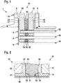
- the tube bundle heat exchanger 1 has a housing 6, a tube sheet 10 with through openings 14, and tubes 50 which lead through the respective through openings 14.
- the tubes 50 contain a first fluid and are supplied by an in an inner housing area (to the right of the tube sheet 10 in Fig. 1 ) located second fluid, so that a heat exchange between the first and the second fluid can take place through the tube walls.
- the inlets and outlets of the tubes 50 are separated by the tube sheet 10 from the inner housing area to the right of the tube sheet 10 and sealed therein as described below.
- the tube sheet 10 comprises a first tube sheet plate 20 with a core 22 and a plastic casing 24 surrounding the core, a second tube sheet plate 30 made of the temperature-resistant material already described above, and a third tube sheet plate 40 with a core 42 and a plastic casing 44 surrounding the core.
- the three tube sheet plates 20, 30, 40 are stacked to form a stack, in which the second tube sheet plate 30 is arranged as an intermediate plate between the first and third tube sheet plates 20, 40.
- the first surface 32 of the second tube sheet plate is directed towards the first tube sheet plate 20 and the opposite second surface 36 of the second tube sheet plate is directed towards the third tube sheet plate 40.
- each of the through-openings 14 two sealing seats 34, 38, each with a sealing ring 52 received therein, are attached in order to seal the respective pipe 50. More precisely, the sealing seats 34, 38 are designed as depressions in the second tube sheet plate 30, which directly surrounds the through opening 14 in a ring-like manner. The rear surface opposite the through opening 14 and a side surface of the sealing seats 34, 38 is formed by the second tube sheet plate 30, and a further side surface of the sealing seats 34, 38 is formed by the first and third tube sheet plates 20, 40, more precisely by their plastic casing 24, 44 educated.
- sealing seats 34, 38 are designed as depressions in the second, temperature-stable tube sheet plate 30 enables a stable and reliable sealing effect.
- the three tube sheet plates 20, 30 and 40 are pressed against one another by a pair of flanges of the housing 6 and thus clamped together.
- the clamping takes place by means of a bracing element (such as a tension element such as a screw), which is not shown, which is passed through the flanges and through the stack of tube sheet plates 20, 30 and 40 in order to press the flanges together and thus compress the stack.
- the bracing element extends here through a flange through-opening 16, which passes through the flanges and through the stack of the three tube sheet plates 20, 30 and 40.
- the bracing elements are arranged exclusively in the edge area (flange area) of the tube sheet.
- the tube sheet plates 20, 30, 40 are mechanically decoupled. Due to the bending stiffness of the tube sheet, in particular of the second tube sheet plate 30, bracing elements or connecting elements located further inside can be dispensed with and it can still be ensured that the tube sheet plates 20, 30, 40 are sufficiently pressed against one another.
- Figure 2 shows an enlarged cross-sectional view of a tube sheet according to a further embodiment of the invention. This embodiment largely corresponds to the embodiment of FIG Figure 1 , and the description of the Figure 1 also applies here accordingly.
- sealing rings 52 and the associated sealing seats 34, 38 differ.
- the sealing rings 52 and the sealing seats 34, 38 have a rectangular (square) cross-section, and in Figure 2 they have a trapezoidal cross-section.
- Other cross-sections described above are also possible.
- Figure 3 shows a cross-sectional view of the second tube sheet plate 30 of a tube sheet according to a further embodiment of the invention. Apart from the illustrated design of the second tube sheet plate 30 (and in particular the sealing seat and the associated sealing rings), the embodiment corresponds to that in FIG Fig. 1 illustrated structure.
- the second tube sheet plate 30 instead of the one in Fig. 1-3 shown two seal seats 34, 38 only a single seal seat 39 attached.
- the sealing seat 39 is attached to the side wall of the through opening 14 in an axially central section of the second tube sheet plate 30 and is thus spaced apart from the first and third tube sheet plates. According to FIG. 4, only a single sealing ring is provided per through opening. All sides of the sealing seat 39 are formed by the temperature-resistant material of the second tube sheet plate 30.
- FIGS. 1-4 can have all of the further aspects described above.
- the embodiments and aspects serve only for illustration and are not intended to limit the scope of protection. The scope of protection is defined by the following claims.
Landscapes
- Engineering & Computer Science (AREA)
- Physics & Mathematics (AREA)
- Thermal Sciences (AREA)
- Mechanical Engineering (AREA)
- General Engineering & Computer Science (AREA)
- Ceramic Engineering (AREA)
- Heat-Exchange Devices With Radiators And Conduit Assemblies (AREA)
- Gasket Seals (AREA)
Description
- Aspekte der Erfindung betreffen einen Rohrboden für einen Rohrbündelwärmeaustauscher. Der Rohrboden umfasst insbesondere einen Stapel von mehreren Rohrbodenplatten mit mindestens einer Durchgangsöffhung zur Aufnahme eines jeweiligen Rohres des Rohrbündelwärmeaustauschers. Die Durchgangsöffnung ist mittels mindestens einem Dichtring abgedichtet. Weitere Aspekte betreffen einen Rohrbündelwärmeaustauscher mit einem solchen Rohrboden und ein Verfahren zum Abdichten eines Rohrbündelwärmeaustauschers insbesondere im Bereich des Rohrbodens.
- Wärmetauscher für den hochkorrosiven Einsatz werden typischerweise mit Rohren aus einem korrosionsfesten Material wie z.B. Graphit, Siliziumcarbid, Glas oder PTFE gebaut. Die Rohre enthalten ein erstes Fluid und werden von einem in einem inneren Gehäusebereich befindlichen zweiten Fluid umgeben, so dass ein Wärmetausch zwischen dem ersten und dem zweiten Fluid durch die Rohrwände erfolgen kann. Die Ein- und Ausgänge der Rohre sind durch einen Rohrboden von dem inneren Gehäusebereich getrennt, so dass sich das ein- und austretende erste Fluid nicht mit dem zweiten Fluid vermischen kann. Hierfür ist eine hervorragende Abdichtung des Rohrbodens entscheidend.
- Der Rohrboden eines typischen solchen Wärmetauschers ist typischerweise aus einer oder mehreren Rohrbodenplatten mit kunststoffummanteltem Metallkern aufgebaut. Die Kunststoffummantelung kann beispielsweise ein chemisch widerstandsfähiges Material wie PFA oder PTFE umfassen, um den Einsatz mit korrosiven Medien (erstes und/oder zweites Fluid) zu ermöglichen.
- Im Gegensatz zu Wärmeaustauschern aus Metall, bei denen die Rohre mit den Rohrböden durch Schweißen und ähnliche Verfahren fluiddicht verbunden sind, ist dieses bei Einsatz von Glas- oder Siliziumcarbidrohren nicht möglich. Stattdessen sind die Rohre durch Durchgangsöffnungen im Rohrboden (ganz oder teilweise) hindurchgeführt und müssen aufwändig abgedichtet werden.
- Beispielsweise ist in der
DE 197 14 423 C2 ein Rohrbündelwärmeaustauscher mit zweigeteilt ausgeführten Rohrböden aus Kunststoff mit darin eingelegter Metallplatte offenbart. Darin sind in Bohrungen angeordnete Rohre jeweils mit Hilfe eines O-Ringes zwischen den einzelnen Rohrböden eingedichtet. Jedoch kann bei derartigen Wärmetauschern die Dichtwirkung nach einiger Zeit nachlassen. Daher ist es erstrebenswert, die Dichtwirkung zu verbessern. - Als weiteres Beispiel zeigt die
DE 10 2010 005216 A1 einen Rohrbündelwärmeaustauscher gemäß dem Oberbegriff von Anspruch 1, mit zweigeteilt ausgeführten Rohrböden aus Kunststoff, zwischen denen eine Zwischenplatte angeordnet ist. In die Durchgangsbohrungen in der Zwischenplatte sind Compoundhülsen einsetzbar. - Vorbekannte Lösungen haben den Nachteil, dass sie einen konstruktiv hohen Aufwand erfordern und dennoch die Langzeitstabilität der Dichtung nicht immer gewährleistet ist.
- Daher ist es eine Aufgabe der Erfindung, einen Rohrbündelwärmeaustauscher zu ermöglichen, bei dem zumindest einige der oben genannten Nachteile verringert sind.
- Insbesondere soll eine möglichst einfache Konstruktion mit möglichst zuverlässiger Dichtwirkung ermöglicht werden.
- Daher wird ein Rohrboden gemäß Anspruch 1, ein Rohrbündelwärmeaustauscher gemäß Anspruch 11, ein Verfahren gemäß Anspruch 14 und eine Verwendung gemäß Anspruch 15 vorgeschlagen. Weitere vorteilhafte Aspekte sind in den abhängigen Ansprüchen, den Figuren und der folgenden Beschreibung dargestellt.
- Gemäß einem Aspekt der Erfindung wird ein Rohrboden für einen Rohrbündelwärmeaustauscher zur Verfügung gestellt. Der Rohrboden umfasst eine erste Rohrbodenplatte mit einem Kern und einer den Kern umgebenden Kunststoffummantelung, eine zweite Rohrbodenplatte aus einem temperaturbeständigen Material (z.B. eine Graphitoder Keramikplatte), und eine dritte Rohrbodenplatte mit einem Kern und einer den Kern umgebenden Kunststoffummantelung.
- Die erste, zweite und dritte Rohrbodenplatte sind zu einem Stapel gestapelt, wobei die zweite Rohrbodenplatte als Zwischenplatte zwischen der ersten und der dritten Rohrbodenplatte (20, 40) angeordnet ist, so dass eine erste Oberfläche der zweiten Rohrbodenplatte zur ersten Rohrbodenplatte gerichtet ist und eine gegenüberliegende zweite Oberfläche der zweiten Rohrbodenplatte zur dritten Rohrbodenplatte gerichtet ist.
- Der Stapel weist zumindest eine Durchgangsöffnung zur Aufnahme eines jeweiligen Rohres des Rohrbündelwärmeaustauschers auf. Der Rohrboden weist für jede der zumindest einen Durchgangsöffnung weiter auf: Je mindestens einen Dichtring zum Abdichten des jeweiligen Rohres, und je mindestens einen Dichtungssitz zur Aufnahme des mindestens einen Dichtrings, wobei der Dichtungssitz eine die jeweilige Durchgangsöffnung unmittelbar ringartig umgebende Vertiefung in der zweiten Rohrbodenplatte ist.
- Aspekte der Erfindung haben den Vorteil, dass eine zweite Rohrbodenplatte aus einem temperaturbeständigen Material zur Verfügung gestellt wird, und dass darin ein Dichtungssitz zur Aufnahme des Dichtrings eingelassen ist. Ein solcher Dichtungssitz ermöglicht eine zuverlässige und langzeitstabile Abdichtung der Rohrbodenplatte.
- Zusätzlich ist die zweite Rohrbodenplatte in einem Stapel zwischen zwei kunststoffummantelten Rohrbodenplatten (erste und dritte Rohrbodenplatte) angeordnet und wird von diesen vor mechanischen Belastungen geschützt. Durch diese Anordnung wird die Stabilität des Rohrbodens weiter erhöht. Durch diese Anordnung als Stapel kann insbesondere ein Rohrboden zur Verfügung gestellt werden, der die vorteilhaften Eigenschaften der jeweiligen Rohrbodenplatten in sich vereint.
- Da die zweite Rohrbodenplatte als Ganzes aus einem temperaturbeständigen Material aufgebaut ist und vorzugsweise aus dem temperaturbeständigen Material besteht, wird die Zuverlässigkeit des Dichtungssitzes noch weiter erhöht. Weiter kann hierdurch ein besonders einfacher Aufbau des Rohrbodens erreicht werden.
- Im Folgenden werden weitere, bevorzugte (d.h. optionale) Aspekte der Erfindung beschrieben. Bezugszeichen beziehen sich zur Illustration auf die im Anschluss genauer beschriebenen Figuren, schränken die Aspekte jedoch nicht auf die dort dargestellten Ausführungsformen ein. Soweit nicht anders angegeben, kann jeder Aspekt mit jedem anderen hierin beschriebenen Aspekt oder jeder anderen hierin beschriebenen Ausführungsform kombiniert werden.
- Gemäß einem Aspekt ist das temperaturbeständige Material der zweiten Rohrbodenplatte dadurch definiert, dass das Material für Temperaturen bis mindestens 250 °C kein substantielles Fließverhalten aufweist. Für Kunststoffe ist diese Bedingung durch eine Formbeständigkeitstemperatur von größer als 250°C definiert, wobei die Formbeständigkeitstemperatur gemäß DIN EN ISO 75-2:2013 (unter einer Last von 0,45 MPa gemäß Verfahren B) zu ermitteln ist. Übliche Kunststoffe wie PFA, PTFE erfüllen diese Bedingung nicht. Eine Ausnahme, für die die Formbeständigkeitstemperatur größer als 250°C ist, ist der Kunststoff PEEK. Auch mit formbeständigen Füllstoffen hochfüllstoffbeladene Kunststoffe können die Bedingung erfüllen. Für Nicht-Kunststoffe gilt das obige Kriterium analog. Dabei sind Stahl, Keramik, Graphit, Glas und weitere Materialien mit ähnlich geringen Fließeigenschaften bei 250 °C stets als temperaturbeständig anzusehen, unabhängig von der obigen Bedingung. Besonders bevorzugt ist das Material der zweiten Rohrbodenplatte eine Keramik.
- Gemäß einem weiteren Aspekt ist das temperaturbeständige Material der zweiten Rohrbodenplatte daher ausgewählt aus den Materialien Stahl, Keramik, Glas, Kunststoff mit einer Formbeständigkeitstemperatur von größer als 250°C wie oben definiert, insbesondere PEEK, und einer Mischung daraus (etwa als Verbundmaterial).
- Gemäß einem weiteren Aspekt hat das Material der zweiten Rohrbodenplatte eine thermische Längenausdehnung α < 20µm/mK für jegliche Temperaturen zwischen -50 °C und 200 °C. Dadurch wird ein sicherer Dichtungssitz auch bei Temperaturschwankungen gewährleistet.
- Gemäß einem weiteren Aspekt hat das Material der zweiten Rohrbodenplatte ein E-Modul > 300GPa. Dadurch wird eine gute Biegesteifigkeit der zweiten Rohrbodenplatte sichergestellt.
- Gemäß einem weiteren Aspekt umfasst der Kern (22, 42) der ersten und/oder der dritten Rohrbodenplatte jeweils zumindest eins von einem Metall (z.B. eine Metall-Legierung) und einem Faserverbundwerkstoff oder besteht daraus. Der Faserverbundwerkstoff kann z.B. ein kohlenstoffbasierter Faserverbundwerkstoff wie etwa CFK und/oder CFC sein. Die Kunststoffummantelung (24, 44) der ersten und/oder der dritten Rohrbodenplatte kann jeweils zumindest ein Fluorpolymer wie etwa PFA und/oder PTFE umfassen. Die Kunststoffummantelung (24, 44) ist gemäß einem Aspekt nicht bzw. aus einem nur eingeschränkt temperaturbeständigen Material (erfüllt z.B. nicht die obige Definition eines temperaturbeständigen Materials).
- Gemäß einem weiteren Aspekt sind die erste und dritte Rohrbodenplatte (20, 40) baugleich ausgeführt, wodurch die Anzahl verschiedener Teile reduziert werden kann.
- Gemäß einem weiteren Aspekt ist die zweite Rohrbodenplatte (30) eine Graphit- oder Keramikplatte, wobei die Keramik vorzugsweise eine Nichtoxid-Keramik wie etwa SSiC, SiSiC, und/oder SN ist. Die zweite Rohrbodenplatte kann das Graphit bzw. die Keramik umfassen oder daraus bestehen. Vorteile dieser Materialien sind ihre Temperaturbeständigkeit bei gleichzeitiger Korrosionsfestigkeit, sowie in dem Stapel vorteilhafte mechanische Eigenschaften.
- Gemäß einem weiteren Aspekt ist die zumindest eine Durchgangsöffnung (14) eine Mehrzahl von Durchgangsöffnungen. Gemäß einem weiteren Aspekt ist die zweite Rohrbodenplatte (30) einstückig, so dass das gleiche monolithische Material der zweiten Rohrbodenplatte (30), z.B. Graphit oder Keramik, an die Mehrzahl der Durchgangsöffnungen (14) angrenzt.
- Gemäß einem weiteren Aspekt ist der mindestens eine Dichtungssitz (34, 38, 39) und/oder der mindestens eine Dichtring (52) mit rechteckigem (insbesondere quadratischem), trapezförmigem, kegelförmigem, konusförmigem oder abschnittsweise ovalem Querschnitt ausgebildet. Der Querschnitt des Dichtungssitzes kann hierbei nach einer Innenseite der jeweiligen Durchgangsöffnung (14) hin offen sein. Weiter kann eine Seite des Dichtungssitzes durch einen Oberflächenabschnitt der ersten bzw. der dritten Rohrbodenplatte gebildet sein. Gemäß einem Abschnitt sind mindestens zwei Seiten des Dichtungssitzes durch einen (vertieften) Oberflächenabschnitt der zweiten Rohrbodenplatte gebildet.
- Gemäß einem weiteren Aspekt ist der je mindestens eine Dichtring (52) je mindestens zwei Dichtringe. Somit umfasst der je mindestens eine Dichtungssitz (34, 38) je mindestens einen ersten und einen zweiten Dichtungssitz. Der erste Dichtungssitz (34) kann etwa als Vertiefung in der ersten Oberfläche (32) der zweiten Rohrbodenplatte (30) angeordnet sein, und der zweite Dichtungssitz (38) kann als Vertiefung in der zweiten Oberfläche (36) der zweiten Rohrbodenplatte (30) angeordnet sein.
- Gemäß einem weiteren Aspekt sind die Dichtringe (52) in dem jeweiligen Dichtungssitz (34, 38) zwischen der zweiten und der ersten Rohrbodenplatte (30, 20) bzw. der zweiten und der dritten Rohrbodenplatte (30, 40) derart eingepresst, dass die Dichtringe auf höchstens einer Seite die jeweilige Kunststoffummantelung (24, 44) berühren, aber vorzugsweise auf mindestens zwei Seiten (davon eine Seite die der Durchgangsöffnung gegenüberliegende Seite) das Material der zweiten Rohrbodenplatte berühren.
- Gemäß einem weiteren Aspekt ist der Dichtungssitz (39) als von der ersten und zweiten Oberfläche (32, 36) der zweiten Rohrbodenplatte (30) beabstandete Vertiefung in einer Seitenwand der Durchgangsöffnung (14) angeordnet.
- Gemäß einem weiteren Aspekt sind die erste, zweite und dritte Rohrbodenplatte (20, 30, 40) durch Verklemmen aneinander gepresst, z.B. durch einen Flansch und/oder einen Zuganker. Bevorzugt wird die Kraft zum Aneinanderpressen der Rohrbodenplatten ausschließlich von einem Randbereich der Rohrbodenplatten (20, 30, 40) her eingeleitet, z.B. durch einen Flansch. Ansonsten sind die Rohrbodenplatten (20, 30, 40) vorzugsweise mechanisch entkoppelt. Eine ausreichende Klemmwirkung kann durch die Steifigkeit der zweiten Rohrbodenplatte vermittelt werden.
- Gemäß einem weiteren Aspekt wird ein Rohrbündelwärmeaustauscher (1) mit dem hierin beschriebenen Rohrboden (10) zur Verfügung gestellt. Der Rohrbündelwärmeaustauscher (1) umfasst für jede der zumindest einen Durchgangsöffnung (14) ein Rohr (50), welches durch die jeweilige Durchgangsöffnung vollständig oder teilweise (mindestens bis zur zweiten Rohrbodenplatte) hindurchführt und welches mittels des in dem mindestens einen Dichtungssitzen (34, 38, 39) liegenden mindestens einen Dichtungsrings (52) eingedichtet ist. Dies schließt das Vorhandensein weiterer Durchgangsöffnungen (etwa für Zuganker) nicht aus.
- Gemäß einem weiteren Aspekt ist das Rohr (50) ein Graphit-, SiC-, oder Glas-Rohr, umfasst also diese Materialien oder besteht aus ihnen.
- Gemäß einem weiteren Aspekt ist der Rohrbündelwärmeaustauscher für ein stark korrodierendes Medium vorgesehen (z.B. starke Säuren wie Flußsäure (HF), Salzsäure (HCl), Salpetersäure (HNO3), oder auch starke Laugen). Die Kunststoffummantelung (24, 44) ist gegenüber dem korrodierenden Medium chemisch beständig.
- Gemäß einem weiteren Aspekt wird ein Verfahren zum Abdichten eines Rohrbündelwärmeaustauschers (1) vorgeschlagen. Das Verfahren umfasst die folgenden Schritte: Ein Rohrboden (10) gemäß einem der Ansprüche 1 bis 10 wird zur Verfügung gestellt; und zumindest ein Rohr (50) des Rohrbündelwärmeaustauschers wird durch die entsprechende Durchgangsöffnung (14) hindurchgeführt und mittels des in dem mindestens einen Dichtungssitz (34, 38, 39) liegenden mindestens einen Dichtungsrings (52) eingedichtet. Das Verfahren kann Teil eines Herstellungsverfahrens des Rohrbündelwärmeaustauschers oder eines Wartungs- bzw. Reparaturverfahrens für den Rohrbündelwärmeaustauscher sein.
- Im Weiteren soll die Erfindung anhand von in Figuren dargestellten Ausführungsbeispielen erläutert werden, aus denen sich weitere Vorteile und Abwandlungen ergeben. Dazu zeigen:
-
Figur 1 zeigt eine Querschnittsansicht eines Rohrbündelwärmeaustauscher mit einem Rohrboden gemäß einer Ausführungsform der Erfindung; -
Figur 2 zeigt eine vergrößerte Querschnittsansicht eines Rohrbodens gemäß einer weiteren Ausführungsform der Erfindung; und -
Figur 3 zeigt eine Querschnittsansicht der zweiten Rohrbodenplatte eines Rohrbodens gemäß einer weiteren Ausführungsform der Erfindung. - Mit Bezug auf
Figur 1 wird im Folgenden ein Rohrbündelwärmeaustauscher 1 gemäß einer Ausführungsform der Erfindung beschrieben. Der Rohrbündelwärmeaustauscher 1 hat ein Gehäuse 6, einen Rohrboden 10 mit Durchgangsöffnungen 14, und Rohre 50, welche durch die jeweiligen Durchgangsöffnungen 14 hindurchführen. - Im Betrieb enthalten die Rohre 50 ein erstes Fluid und werden von einem in einem inneren Gehäusebereich (rechts des Rohrbodens 10 in
Fig. 1 ) befindlichen zweiten Fluid umgeben, so dass ein Wärmetausch zwischen dem ersten und dem zweiten Fluid durch die Rohrwände erfolgen kann. Die Ein- und Ausgänge der Rohre 50 (zur linken Seite des Rohrbodens 10 inFig. 1 ) sind durch den Rohrboden 10 von dem inneren Gehäusebereich rechts des Rohrbodens 10 getrennt und darin wie im Folgenden beschrieben eingedichtet. - Der Rohrboden 10 umfasst eine erste Rohrbodenplatte 20 mit einem Kern 22 und einer den Kern umgebenden Kunststoffummantelung 24, eine zweite Rohrbodenplatte 30 aus dem bereits oben beschriebenen temperaturbeständigen Material, und eine dritte Rohrbodenplatte 40 mit einem Kern 42 und einer den Kern umgebenden Kunststoffummantelung 44.
- Die drei Rohrbodenplatten 20, 30, 40 sind zu einem Stapel gestapelt, bei dem die zweite Rohrbodenplatte 30 als Zwischenplatte zwischen der ersten und der dritten Rohrbodenplatte 20, 40 angeordnet ist. Mit anderen Worten ist die erste Oberfläche 32 der zweiten Rohrbodenplatte zur ersten Rohrbodenplatte 20 gerichtet und die gegenüberliegende zweite Oberfläche 36 der zweiten Rohrbodenplatte zur dritten Rohrbodenplatte 40 gerichtet.
- In jeder der Durchgangsöffnungen 14 sind je zwei Dichtungssitze 34, 38 mit jeweils einem darin aufgenommenen Dichtring 52 angebracht, um das jeweilige Rohr 50 abzudichten. Genauer sind die Dichtungssitze 34, 38 eine als Vertiefungen in der zweiten Rohrbodenplatte 30 ausgebildet, welche die Durchgangsöffnung 14 unmittelbar ringartig umgibt. Die der Durchgangsöffnung 14 gegenüberliegende Rückfläche und eine Seitenfläche der Dichtungssitze 34, 38 wird durch die zweite Rohrbodenplatte 30 gebildet, und eine weitere Seitenfläche der Dichtungssitze 34, 38 wird durch die erste bzw. dritte Rohrbodenplatte 20, 40, genauer durch deren Kunststoffummantelung 24, 44 gebildet.
- Dadurch, dass die Dichtungssitze 34, 38 eine als Vertiefungen in der zweiten, temperaturstabilen Rohrbodenplatte 30 ausgebildet sind, wird eine stabile und zuverlässige Dichtwirkung ermöglicht.
- Die drei Rohrbodenplatten 20, 30 und 40 sind durch ein Paar von Flanschen des Gehäuses 6 aneinander gepresst und somit miteinander verklemmt. Das Verklemmen erfolgt mittels eines nicht dargestellen Verspannelements (etwa eines Zugelements wie einer Schraube), welches durch die Flansche und durch den Stapel der Rohrbodenplatten 20, 30 und 40 hindurchgeführt wird, um die Flansche aneinanderzupressen und somit den Stapel zusammenzupressen. Das Verspannelement erstreckt sich hier durch eine Flansch-Durchgangsöffnung 16, welche durch die Flansche und durch den Stapel der drei Rohrbodenplatten 20, 30 und 40 hindurchgeht.
- Die Verspannelemente sind ausschließlich im Randbereich (Flanschbereich) des Rohrbodens angeordnet. Im Inneren des Gehäuses 6 sind die Rohrbodenplatten 20, 30, 40 dagegen mechanisch entkoppelt. Aufgrund der Verbiegesteifigkeit des Rohrbodens, insbesondere der zweiten Rohrbodenplatte 30, kann auf weiter innenliegende Verspannelemente oder Verbindungselemente verzichtet werden und dennoch sichergestellt werden, dass die Rohrbodenplatten 20, 30, 40 ausreichend aneinandergepresst werden.
-
Figur 2 zeigt eine vergrößerte Querschnittsansicht eines Rohrbodens gemäß einer weiteren Ausführungsform der Erfindung. Diese Ausführungsform entspricht weitgehend der Ausführungsform derFigur 1 , und die Beschreibung derFigur 1 gilt auch entsprechend hier. - Lediglich die Querschnittsform der Dichtungsringe 52 und der zugehörigen Dichtungssitze 34, 38 unterscheidet sich. In
Figur 1 haben die Dichtungsringe 52 und die Dichtungssitze 34, 38 einen rechteckigen (quadratischen) Querschnitt, und inFigur 2 haben sie einen trapezförmigen Querschnitt. Auch weitere oben beschriebene Querschnitte sind möglich. -
Figur 3 zeigt eine Querschnittsansicht der zweiten Rohrbodenplatte 30 eines Rohrbodens gemäß einer weiteren Ausführungsform der Erfindung. Abgesehen von der dargestellten Gestaltung der zweiten Rohrbodenplatte 30 (und insbesondere von dem Dichtungssitz und der zugehörigen Dichtungsringe) entspricht die Ausfuhrungsform dem inFig. 1 dargestellten Aufbau. - In der zweiten Rohrbodenplatte 30 gemäß Figur 4 ist statt der in
Fig. 1-3 dargestellten zwei Dichtungssitze 34, 38 nur ein einziger Dichtungssitz 39 angebracht. Der Dichtungssitz 39 ist an der Seitenwand der Durchgangsöffnung 14 in einem axial mittigen Abschnitt der zweiten Rohrbodenplatte 30 angebracht und somit von der ersten und dritten Rohrbodenplatte beabstandet. Gemäß Figur 4 ist somit nur ein einziger Dichtungsring pro Durchgangsöffnung vorgesehen. Sämtliche Seiten des Dichtungssitzes 39 werden durch das temperaturfeste Material der zweiten Rohrbodenplatte 30 gebildet. - Soweit nicht anders dargestellt, können die Ausführungsformen der Figuren 1-4 sämtliche oben beschriebenen weiteren Aspekte aufweisen. Die Ausführungsformen und Aspekte dienen lediglich zur Illustration und sollen den Schutzbereich nicht einschränken. Der Schutzbereich wird durch die folgenden Ansprüche definiert.
Claims (15)
- Rohrboden (10) für einen Rohrbündelwärmeaustauscher (1), der Rohrboden umfassend:- eine erste Rohrbodenplatte (20) mit einem Kern (22) und einer den Kern umgebenden Kunststoffummantelung (24),- eine zweite Rohrbodenplatte (30) aus einem temperaturbeständigen Material, und- eine dritte Rohrbodenplatte (40) mit einem Kern (42) und einer den Kern umgebenden Kunststoffummantelung (44), wobeidie erste, zweite und dritte Rohrbodenplatte zu einem Stapel gestapelt sind, wobei die zweite Rohrbodenplatte (30) als Zwischenplatte zwischen der ersten und der dritten Rohrbodenplatte (20, 40) angeordnet ist, so dass eine erste Oberfläche (32) der zweiten Rohrbodenplatte zur ersten Rohrbodenplatte (20) gerichtet ist und eine gegenüberliegende zweite Oberfläche (36) der zweiten Rohrbodenplatte zur dritten Rohrbodenplatte (40) gerichtet ist, und wobeider Stapel zumindest eine Durchgangsöffnung (14) zur Aufnahme eines jeweiligen Rohres (50) des Rohrbündelwärmeaustauschers aufweist, und wobei der Rohrboden für jede der zumindest einen Durchgangsöffnung (14) weiter aufweist:- je mindestens einen Dichtring (52) zum Abdichten des jeweiligen Rohres,- je mindestens einen Dichtungssitz (34, 38, 39) zur Aufnahme des mindestens einen Dichtrings (52), wobei der Dichtungssitz eine die jeweilige Durchgangsöffnung unmittelbar ringartig umgebende Vertiefung in der zweiten Rohrbodenplatte (30) ist,
dadurch gekennzeichnet, dass das temperaturbeständige Material kein substantielles Fließverhalten für Temperaturen bis mindestens 200 °C und keine substantielle Wärmeausdehnung für Temperaturen zwischen -50 °C und 200 °C aufweist. - Rohrboden für einen Rohrbündelwärmeaustauscher nach Anspruch 1, wobei der Kern (22, 42) der ersten und/oder der dritten Rohrbodenplatte jeweils zumindest eins von einem Metall und einem Faserverbundwerkstoff umfasst.
- Rohrboden für einen Rohrbündelwärmeaustauscher nach einem beliebigen der vorangehenden Ansprüche, wobei die erste und dritte Rohrbodenplatte (20, 40) baugleich ausgeführt sind.
- Rohrboden für einen Rohrbündelwärmeaustauscher nach einem beliebigen der vorangehenden Ansprüche, wobei die zweite Rohrbodenplatte (30) eine Graphitoder Keramikplatte ist.
- Rohrboden für einen Rohrbündelwärmeaustauscher nach einem beliebigen der vorangehenden Ansprüche, wobei die zumindest eine Durchgangsöffnung (14) eine Mehrzahl von Durchgangsöffnungen sind, und wobei die zweite Rohrbodenplatte (30) einstückig ist, so dass das gleiche monolithische Material der zweiten Rohrbodenplatte (30) an die Mehrzahl der Durchgangsöffnungen (14) angrenzt.
- Rohrboden für einen Rohrbündelwärmeaustauscher nach einem beliebigen der vorangehenden Ansprüche, wobei der mindestens eine Dichtring (52) mit rechteckigem, trapezförmigem, kegelförmigem, konusförmigem oder abschnittsweise ovalem Querschnitt ausgebildet ist.
- Rohrboden für einen Rohrbündelwärmeaustauscher einem beliebigen der vorangehenden Ansprüche, wobei der je mindestens eine Dichtring (52) je mindestens zwei Dichtringe sind, und wobei der je mindestens einen Dichtungssitz (34, 38) je mindestens einen ersten und einen zweiten Dichtungssitz umfassen, wobei der erste Dichtungssitz (34) als Vertiefung in der ersten Oberfläche (32) der zweiten Rohrbodenplatte (30) angeordnet ist und der zweite Dichtungssitz (38) als Vertiefung in der zweiten Oberfläche (36) der zweiten Rohrbodenplatte (30) angeordnet ist.
- Rohrboden für einen Rohrbündelwärmeaustauscher nach einem beliebigen der vorangehenden Ansprüche, wobei die Dichtringe (52) in dem jeweiligen Dichtungssitz (34, 38) zwischen der zweiten und der ersten Rohrbodenplatte (30, 20) bzw. der zweiten und der dritten Rohrbodenplatte (30, 40) derart eingepresst sind, dass die Dichtringe auf höchstens einer Seite die jeweilige Kunststoffummantelung (24, 44) berühren,
- Rohrboden für einen Rohrbündelwärmeaustauscher nach einem beliebigen der Ansprüche 1 bis 6, wobei der Dichtungssitz (39) als von der ersten und zweiten Oberfläche (32, 36) der zweiten Rohrbodenplatte (30) beabstandete Vertiefung in einer Seitenwand der Durchgangsöffnung (14) angeordnet ist.
- Rohrboden für einen Rohrbündelwärmeaustauscher nach einem beliebigen der vorangehenden Ansprüche, wobei die erste, zweite und dritte Rohrbodenplatte (20, 30, 40) durch Verklemmen aneinander gepresst sind.
- Rohrbündelwärmeaustauscher (1), umfassend den Rohrboden (10) nach einem beliebigen der vorangehenden Ansprüche, und für jede der zumindest einen Durchgangsöffnung (14) ein Rohr (50), welches durch die jeweilige Durchgangsöffnung hindurchführt und mittels des in dem mindestens einen Dichtungssitz (34, 38, 39) liegenden mindestens einen Dichtungsrings (52) eingedichtet ist.
- Rohrbündelwärmeaustauscher nach Anspruch 11, wobei das Rohr (50) ein Graphit-, SiC-, oder Glas-Rohr ist.
- Verwendung des Rohrbündelwärmeaustauscher nach Anspruch 11 oder 12, wobei der Rohrbündelwärmeaustauscher für ein korrodierendes Medium vorgesehen ist und wobei die Kunststoffummantelung (24, 44) gegenüber dem korrodierenden Medium chemisch beständig ist.
- Verfahren zum Abdichten eines Rohrbündelwärmeaustauschers (1), das Verfahren umfassend:- Ein Rohrboden (10) gemäß einem der Ansprüche 1 bis 10 wird zur Verfügung gestellt,- zumindest ein Rohr (50) des Rohrbündelwärmeaustauschers wird durch die entsprechende Durchgangsöffnung (14) hindurchgeführt und mittels des in dem mindestens einen Dichtungssitz (34, 38, 39) liegenden mindestens einen Dichtungsrings (52) eingedichtet.
- Verwendung des Rohrbodens (10) gemäß einem der Ansprüche 1 bis 10 zum Abdichten des Rohrbündelwärmeaustauschers (1).
Applications Claiming Priority (2)
| Application Number | Priority Date | Filing Date | Title |
|---|---|---|---|
| DE102018001548.4A DE102018001548A1 (de) | 2018-02-28 | 2018-02-28 | Rohrbündelwärmeaustauscher sowie Rohrboden und Verfahren zum Abdichten desselben |
| PCT/EP2019/054870 WO2019166493A1 (de) | 2018-02-28 | 2019-02-27 | Rohrbündelwärmeaustauscher sowie rohrboden und verfahren zum abdichten desselben |
Publications (2)
| Publication Number | Publication Date |
|---|---|
| EP3759411A1 EP3759411A1 (de) | 2021-01-06 |
| EP3759411B1 true EP3759411B1 (de) | 2022-01-05 |
Family
ID=65628767
Family Applications (1)
| Application Number | Title | Priority Date | Filing Date |
|---|---|---|---|
| EP19708280.3A Active EP3759411B1 (de) | 2018-02-28 | 2019-02-27 | Rohrbündelwärmeaustauscher sowie rohrboden und verfahren zum abdichten desselben |
Country Status (8)
| Country | Link |
|---|---|
| US (1) | US11378342B2 (de) |
| EP (1) | EP3759411B1 (de) |
| JP (1) | JP7116180B2 (de) |
| KR (1) | KR102447879B1 (de) |
| CN (1) | CN111788451A (de) |
| DE (1) | DE102018001548A1 (de) |
| ES (1) | ES2905709T3 (de) |
| WO (1) | WO2019166493A1 (de) |
Families Citing this family (1)
| Publication number | Priority date | Publication date | Assignee | Title |
|---|---|---|---|---|
| DE102024108712A1 (de) * | 2024-03-27 | 2025-10-02 | Sgl Carbon Se | Bauteilkombination für eine verfahrenstechnische Anlage |
Family Cites Families (17)
| Publication number | Priority date | Publication date | Assignee | Title |
|---|---|---|---|---|
| DE3365996D1 (en) * | 1982-05-04 | 1986-10-16 | Corning Ltd | Method for the production of a tube heat exchangerunit |
| JPS6086792U (ja) * | 1983-11-17 | 1985-06-14 | 日立化成工業株式会社 | 套管式熱交換器 |
| JPS62108999A (ja) * | 1985-11-07 | 1987-05-20 | Mitsubishi Heavy Ind Ltd | 伝熱管の支持構造 |
| CN2240706Y (zh) * | 1995-08-20 | 1996-11-20 | 夏有年 | 壳程搪玻璃列管换热器的管板和换热管及其连接密封装置 |
| CN2253463Y (zh) * | 1996-01-13 | 1997-04-30 | 李宝忠 | 搪玻璃套管换热器 |
| DE19714423C2 (de) * | 1997-04-08 | 2003-05-08 | Schnabel Gmbh & Co Kg Dr | Rohrbündelwärmeaustauscher |
| JP2002350092A (ja) * | 2001-05-28 | 2002-12-04 | Kawasaki Heavy Ind Ltd | 熱交換器とこれを用いたガスタービン装置 |
| ITMI20022449A1 (it) | 2002-11-19 | 2004-05-20 | Tycon Technoglass S P A | Scambiatore di calore con fascio tubiero in carburo di silicio e |
| ITMI20031268A1 (it) * | 2003-06-24 | 2004-12-25 | Italprotec S A S Di Cotogni Carla E C | Scambiatore di calore a fascio tubiero. |
| US20050034847A1 (en) | 2003-08-11 | 2005-02-17 | Robert Graham | Monolithic tube sheet and method of manufacture |
| DE202004021912U1 (de) * | 2004-03-31 | 2012-11-23 | Sgl Carbon Se | Rohrbündelwärmeaustauscher |
| US8256503B2 (en) * | 2008-07-17 | 2012-09-04 | Cox Richard D | Plastic heat exchanger with extruded shell |
| US20100116478A1 (en) * | 2008-11-12 | 2010-05-13 | Exxonmobil Research And Engineering Company | Displaceable baffle for a heat exchanger and method for reducing vibration for the same |
| DE102010005216B4 (de) * | 2010-01-21 | 2016-06-02 | Gab Neumann Gmbh | Rohrbündelwärmeaustauscher |
| CN103968704A (zh) * | 2014-04-15 | 2014-08-06 | 张家港市科华化工装备制造有限公司 | 一种提高热管安装密封性的换热器 |
| DE202015009185U1 (de) * | 2015-08-26 | 2016-11-11 | Petr M. Trofimov | Rohrbündelwärmetauscher |
| CN105910474B (zh) * | 2016-06-29 | 2018-03-30 | 李志典 | 多管板换热器 |
-
2018
- 2018-02-28 DE DE102018001548.4A patent/DE102018001548A1/de not_active Ceased
-
2019
- 2019-02-27 ES ES19708280T patent/ES2905709T3/es active Active
- 2019-02-27 KR KR1020207027425A patent/KR102447879B1/ko active Active
- 2019-02-27 US US16/971,392 patent/US11378342B2/en active Active
- 2019-02-27 WO PCT/EP2019/054870 patent/WO2019166493A1/de not_active Ceased
- 2019-02-27 EP EP19708280.3A patent/EP3759411B1/de active Active
- 2019-02-27 JP JP2020545300A patent/JP7116180B2/ja active Active
- 2019-02-27 CN CN201980015602.5A patent/CN111788451A/zh active Pending
Also Published As
| Publication number | Publication date |
|---|---|
| JP7116180B2 (ja) | 2022-08-09 |
| US20210207892A1 (en) | 2021-07-08 |
| US11378342B2 (en) | 2022-07-05 |
| WO2019166493A1 (de) | 2019-09-06 |
| EP3759411A1 (de) | 2021-01-06 |
| BR112020016231A2 (pt) | 2020-12-15 |
| KR20200125655A (ko) | 2020-11-04 |
| JP2021515175A (ja) | 2021-06-17 |
| DE102018001548A1 (de) | 2019-08-29 |
| CN111788451A (zh) | 2020-10-16 |
| ES2905709T3 (es) | 2022-04-11 |
| KR102447879B1 (ko) | 2022-09-26 |
Similar Documents
| Publication | Publication Date | Title |
|---|---|---|
| EP2335001B1 (de) | Bauteil aus einem stapel keramischer platten | |
| DE2733611C2 (de) | Transportleitung mit keramischer Innenisolierung zur Führung heißer Fluide | |
| DE202008010025U1 (de) | Metallische Dichtung, insbesondere Abgaskrümmerdichtung | |
| EP1842023B1 (de) | Wärmeübertrager, insbesondere ladeluftkühler oder kühlmittelkühler für kraftfahrzeuge | |
| EP3022510A1 (de) | Wärmeübertrager mit elastischem element | |
| EP0355662A2 (de) | Aktiv gekühlter Wärmeschutzschild | |
| WO2014083036A1 (de) | Plattenwärmeaustauscher in abgedichteter bauweise | |
| WO2009018792A1 (de) | Verspannung eines hochtemperaturbrennstoffzellenstacks | |
| DE102019218783A1 (de) | Flachdichtung und deren Verwendung | |
| EP3759411A1 (de) | Rohrbündelwärmeaustauscher sowie rohrboden und verfahren zum abdichten desselben | |
| DE2450914C2 (de) | Dichtung, insbesondere Flachdichtung | |
| DE60217492T2 (de) | Plattenwärmetauscher | |
| DE102010005216B4 (de) | Rohrbündelwärmeaustauscher | |
| DE112017005016T5 (de) | Wärmetauscher mit großer Haltbarkeit | |
| DE102013202787A1 (de) | Flanschverbindung für Rohrleitungen | |
| EP3070426B1 (de) | Abgaswärmeübertrager | |
| DE19730389C2 (de) | Wärmetauscher | |
| EP3830510B1 (de) | Abstützung von rohren gewickelter wärmeübertrager | |
| DE102020102089A1 (de) | Wärmetauscherrohr | |
| DE202004021912U1 (de) | Rohrbündelwärmeaustauscher | |
| DE102007063641B4 (de) | Verbindungsanordnung für den Installationsbereich | |
| DE102018106343B4 (de) | Zwischenelement für Wärmeableiteinrichtungen und Wärmeableiteinrichtung | |
| WO2019170288A1 (de) | Kühlrippenanordnung, produktsammelrohr und dampfreformer | |
| DE102019214497A1 (de) | Rohrkörper-Anordnung für eine Temperiereinrichtung, Temperiereinrichtung sowie elektrische Vorrichtung | |
| WO2019229148A1 (de) | Wärmetauscher |
Legal Events
| Date | Code | Title | Description |
|---|---|---|---|
| STAA | Information on the status of an ep patent application or granted ep patent |
Free format text: STATUS: UNKNOWN |
|
| STAA | Information on the status of an ep patent application or granted ep patent |
Free format text: STATUS: THE INTERNATIONAL PUBLICATION HAS BEEN MADE |
|
| PUAI | Public reference made under article 153(3) epc to a published international application that has entered the european phase |
Free format text: ORIGINAL CODE: 0009012 |
|
| STAA | Information on the status of an ep patent application or granted ep patent |
Free format text: STATUS: REQUEST FOR EXAMINATION WAS MADE |
|
| 17P | Request for examination filed |
Effective date: 20200928 |
|
| AK | Designated contracting states |
Kind code of ref document: A1 Designated state(s): AL AT BE BG CH CY CZ DE DK EE ES FI FR GB GR HR HU IE IS IT LI LT LU LV MC MK MT NL NO PL PT RO RS SE SI SK SM TR |
|
| AX | Request for extension of the european patent |
Extension state: BA ME |
|
| DAV | Request for validation of the european patent (deleted) | ||
| DAX | Request for extension of the european patent (deleted) | ||
| GRAP | Despatch of communication of intention to grant a patent |
Free format text: ORIGINAL CODE: EPIDOSNIGR1 |
|
| STAA | Information on the status of an ep patent application or granted ep patent |
Free format text: STATUS: GRANT OF PATENT IS INTENDED |
|
| INTG | Intention to grant announced |
Effective date: 20210810 |
|
| GRAS | Grant fee paid |
Free format text: ORIGINAL CODE: EPIDOSNIGR3 |
|
| GRAA | (expected) grant |
Free format text: ORIGINAL CODE: 0009210 |
|
| STAA | Information on the status of an ep patent application or granted ep patent |
Free format text: STATUS: THE PATENT HAS BEEN GRANTED |
|
| AK | Designated contracting states |
Kind code of ref document: B1 Designated state(s): AL AT BE BG CH CY CZ DE DK EE ES FI FR GB GR HR HU IE IS IT LI LT LU LV MC MK MT NL NO PL PT RO RS SE SI SK SM TR |
|
| REG | Reference to a national code |
Ref country code: GB Ref legal event code: FG4D Free format text: NOT ENGLISH |
|
| REG | Reference to a national code |
Ref country code: CH Ref legal event code: EP |
|
| REG | Reference to a national code |
Ref country code: AT Ref legal event code: REF Ref document number: 1460956 Country of ref document: AT Kind code of ref document: T Effective date: 20220115 |
|
| REG | Reference to a national code |
Ref country code: DE Ref legal event code: R096 Ref document number: 502019003174 Country of ref document: DE |
|
| REG | Reference to a national code |
Ref country code: IE Ref legal event code: FG4D Free format text: LANGUAGE OF EP DOCUMENT: GERMAN |
|
| REG | Reference to a national code |
Ref country code: NL Ref legal event code: FP |
|
| REG | Reference to a national code |
Ref country code: ES Ref legal event code: FG2A Ref document number: 2905709 Country of ref document: ES Kind code of ref document: T3 Effective date: 20220411 |
|
| REG | Reference to a national code |
Ref country code: LT Ref legal event code: MG9D |
|
| PG25 | Lapsed in a contracting state [announced via postgrant information from national office to epo] |
Ref country code: SE Free format text: LAPSE BECAUSE OF FAILURE TO SUBMIT A TRANSLATION OF THE DESCRIPTION OR TO PAY THE FEE WITHIN THE PRESCRIBED TIME-LIMIT Effective date: 20220105 Ref country code: RS Free format text: LAPSE BECAUSE OF FAILURE TO SUBMIT A TRANSLATION OF THE DESCRIPTION OR TO PAY THE FEE WITHIN THE PRESCRIBED TIME-LIMIT Effective date: 20220105 Ref country code: PT Free format text: LAPSE BECAUSE OF FAILURE TO SUBMIT A TRANSLATION OF THE DESCRIPTION OR TO PAY THE FEE WITHIN THE PRESCRIBED TIME-LIMIT Effective date: 20220505 Ref country code: NO Free format text: LAPSE BECAUSE OF FAILURE TO SUBMIT A TRANSLATION OF THE DESCRIPTION OR TO PAY THE FEE WITHIN THE PRESCRIBED TIME-LIMIT Effective date: 20220405 Ref country code: LT Free format text: LAPSE BECAUSE OF FAILURE TO SUBMIT A TRANSLATION OF THE DESCRIPTION OR TO PAY THE FEE WITHIN THE PRESCRIBED TIME-LIMIT Effective date: 20220105 Ref country code: HR Free format text: LAPSE BECAUSE OF FAILURE TO SUBMIT A TRANSLATION OF THE DESCRIPTION OR TO PAY THE FEE WITHIN THE PRESCRIBED TIME-LIMIT Effective date: 20220105 Ref country code: BG Free format text: LAPSE BECAUSE OF FAILURE TO SUBMIT A TRANSLATION OF THE DESCRIPTION OR TO PAY THE FEE WITHIN THE PRESCRIBED TIME-LIMIT Effective date: 20220405 |
|
| PG25 | Lapsed in a contracting state [announced via postgrant information from national office to epo] |
Ref country code: PL Free format text: LAPSE BECAUSE OF FAILURE TO SUBMIT A TRANSLATION OF THE DESCRIPTION OR TO PAY THE FEE WITHIN THE PRESCRIBED TIME-LIMIT Effective date: 20220105 Ref country code: LV Free format text: LAPSE BECAUSE OF FAILURE TO SUBMIT A TRANSLATION OF THE DESCRIPTION OR TO PAY THE FEE WITHIN THE PRESCRIBED TIME-LIMIT Effective date: 20220105 Ref country code: GR Free format text: LAPSE BECAUSE OF FAILURE TO SUBMIT A TRANSLATION OF THE DESCRIPTION OR TO PAY THE FEE WITHIN THE PRESCRIBED TIME-LIMIT Effective date: 20220406 Ref country code: FI Free format text: LAPSE BECAUSE OF FAILURE TO SUBMIT A TRANSLATION OF THE DESCRIPTION OR TO PAY THE FEE WITHIN THE PRESCRIBED TIME-LIMIT Effective date: 20220105 |
|
| PG25 | Lapsed in a contracting state [announced via postgrant information from national office to epo] |
Ref country code: IS Free format text: LAPSE BECAUSE OF FAILURE TO SUBMIT A TRANSLATION OF THE DESCRIPTION OR TO PAY THE FEE WITHIN THE PRESCRIBED TIME-LIMIT Effective date: 20220505 |
|
| REG | Reference to a national code |
Ref country code: DE Ref legal event code: R097 Ref document number: 502019003174 Country of ref document: DE |
|
| REG | Reference to a national code |
Ref country code: CH Ref legal event code: PL |
|
| PG25 | Lapsed in a contracting state [announced via postgrant information from national office to epo] |
Ref country code: SM Free format text: LAPSE BECAUSE OF FAILURE TO SUBMIT A TRANSLATION OF THE DESCRIPTION OR TO PAY THE FEE WITHIN THE PRESCRIBED TIME-LIMIT Effective date: 20220105 Ref country code: SK Free format text: LAPSE BECAUSE OF FAILURE TO SUBMIT A TRANSLATION OF THE DESCRIPTION OR TO PAY THE FEE WITHIN THE PRESCRIBED TIME-LIMIT Effective date: 20220105 Ref country code: RO Free format text: LAPSE BECAUSE OF FAILURE TO SUBMIT A TRANSLATION OF THE DESCRIPTION OR TO PAY THE FEE WITHIN THE PRESCRIBED TIME-LIMIT Effective date: 20220105 Ref country code: MC Free format text: LAPSE BECAUSE OF FAILURE TO SUBMIT A TRANSLATION OF THE DESCRIPTION OR TO PAY THE FEE WITHIN THE PRESCRIBED TIME-LIMIT Effective date: 20220105 Ref country code: LU Free format text: LAPSE BECAUSE OF NON-PAYMENT OF DUE FEES Effective date: 20220227 Ref country code: EE Free format text: LAPSE BECAUSE OF FAILURE TO SUBMIT A TRANSLATION OF THE DESCRIPTION OR TO PAY THE FEE WITHIN THE PRESCRIBED TIME-LIMIT Effective date: 20220105 Ref country code: DK Free format text: LAPSE BECAUSE OF FAILURE TO SUBMIT A TRANSLATION OF THE DESCRIPTION OR TO PAY THE FEE WITHIN THE PRESCRIBED TIME-LIMIT Effective date: 20220105 Ref country code: CZ Free format text: LAPSE BECAUSE OF FAILURE TO SUBMIT A TRANSLATION OF THE DESCRIPTION OR TO PAY THE FEE WITHIN THE PRESCRIBED TIME-LIMIT Effective date: 20220105 |
|
| PLBE | No opposition filed within time limit |
Free format text: ORIGINAL CODE: 0009261 |
|
| STAA | Information on the status of an ep patent application or granted ep patent |
Free format text: STATUS: NO OPPOSITION FILED WITHIN TIME LIMIT |
|
| PG25 | Lapsed in a contracting state [announced via postgrant information from national office to epo] |
Ref country code: AL Free format text: LAPSE BECAUSE OF FAILURE TO SUBMIT A TRANSLATION OF THE DESCRIPTION OR TO PAY THE FEE WITHIN THE PRESCRIBED TIME-LIMIT Effective date: 20220105 |
|
| 26N | No opposition filed |
Effective date: 20221006 |
|
| PG25 | Lapsed in a contracting state [announced via postgrant information from national office to epo] |
Ref country code: LI Free format text: LAPSE BECAUSE OF NON-PAYMENT OF DUE FEES Effective date: 20220228 Ref country code: IE Free format text: LAPSE BECAUSE OF NON-PAYMENT OF DUE FEES Effective date: 20220227 Ref country code: CH Free format text: LAPSE BECAUSE OF NON-PAYMENT OF DUE FEES Effective date: 20220228 |
|
| PG25 | Lapsed in a contracting state [announced via postgrant information from national office to epo] |
Ref country code: SI Free format text: LAPSE BECAUSE OF FAILURE TO SUBMIT A TRANSLATION OF THE DESCRIPTION OR TO PAY THE FEE WITHIN THE PRESCRIBED TIME-LIMIT Effective date: 20220105 |
|
| PG25 | Lapsed in a contracting state [announced via postgrant information from national office to epo] |
Ref country code: MK Free format text: LAPSE BECAUSE OF FAILURE TO SUBMIT A TRANSLATION OF THE DESCRIPTION OR TO PAY THE FEE WITHIN THE PRESCRIBED TIME-LIMIT Effective date: 20220105 Ref country code: CY Free format text: LAPSE BECAUSE OF FAILURE TO SUBMIT A TRANSLATION OF THE DESCRIPTION OR TO PAY THE FEE WITHIN THE PRESCRIBED TIME-LIMIT Effective date: 20220105 |
|
| PG25 | Lapsed in a contracting state [announced via postgrant information from national office to epo] |
Ref country code: HU Free format text: LAPSE BECAUSE OF FAILURE TO SUBMIT A TRANSLATION OF THE DESCRIPTION OR TO PAY THE FEE WITHIN THE PRESCRIBED TIME-LIMIT; INVALID AB INITIO Effective date: 20190227 |
|
| PG25 | Lapsed in a contracting state [announced via postgrant information from national office to epo] |
Ref country code: TR Free format text: LAPSE BECAUSE OF FAILURE TO SUBMIT A TRANSLATION OF THE DESCRIPTION OR TO PAY THE FEE WITHIN THE PRESCRIBED TIME-LIMIT Effective date: 20220105 |
|
| P01 | Opt-out of the competence of the unified patent court (upc) registered |
Free format text: CASE NUMBER: APP_37850/2024 Effective date: 20240625 |
|
| PG25 | Lapsed in a contracting state [announced via postgrant information from national office to epo] |
Ref country code: MT Free format text: LAPSE BECAUSE OF FAILURE TO SUBMIT A TRANSLATION OF THE DESCRIPTION OR TO PAY THE FEE WITHIN THE PRESCRIBED TIME-LIMIT Effective date: 20220105 |
|
| REG | Reference to a national code |
Ref country code: AT Ref legal event code: MM01 Ref document number: 1460956 Country of ref document: AT Kind code of ref document: T Effective date: 20240227 |
|
| PG25 | Lapsed in a contracting state [announced via postgrant information from national office to epo] |
Ref country code: AT Free format text: LAPSE BECAUSE OF NON-PAYMENT OF DUE FEES Effective date: 20240227 |
|
| PGFP | Annual fee paid to national office [announced via postgrant information from national office to epo] |
Ref country code: NL Payment date: 20260218 Year of fee payment: 8 |
|
| PGFP | Annual fee paid to national office [announced via postgrant information from national office to epo] |
Ref country code: GB Payment date: 20260219 Year of fee payment: 8 |
|
| PGFP | Annual fee paid to national office [announced via postgrant information from national office to epo] |
Ref country code: ES Payment date: 20260319 Year of fee payment: 8 |
|
| PGFP | Annual fee paid to national office [announced via postgrant information from national office to epo] |
Ref country code: DE Payment date: 20260217 Year of fee payment: 8 |
|
| PGFP | Annual fee paid to national office [announced via postgrant information from national office to epo] |
Ref country code: AT Payment date: 20260410 Year of fee payment: 5 |
|
| PGFP | Annual fee paid to national office [announced via postgrant information from national office to epo] |
Ref country code: BE Payment date: 20260218 Year of fee payment: 8 Ref country code: IT Payment date: 20260227 Year of fee payment: 8 |
|
| PGFP | Annual fee paid to national office [announced via postgrant information from national office to epo] |
Ref country code: FR Payment date: 20260223 Year of fee payment: 8 |