EP3759041B1 - Aufzugsschachttüranordnung und installationsverfahren dafür - Google Patents
Aufzugsschachttüranordnung und installationsverfahren dafür Download PDFInfo
- Publication number
- EP3759041B1 EP3759041B1 EP18908116.9A EP18908116A EP3759041B1 EP 3759041 B1 EP3759041 B1 EP 3759041B1 EP 18908116 A EP18908116 A EP 18908116A EP 3759041 B1 EP3759041 B1 EP 3759041B1
- Authority
- EP
- European Patent Office
- Prior art keywords
- landing door
- elevator
- door unit
- fixing elements
- unit
- Prior art date
- Legal status (The legal status is an assumption and is not a legal conclusion. Google has not performed a legal analysis and makes no representation as to the accuracy of the status listed.)
- Active
Links
Images

Classifications
-
- B—PERFORMING OPERATIONS; TRANSPORTING
- B66—HOISTING; LIFTING; HAULING
- B66B—ELEVATORS; ESCALATORS OR MOVING WALKWAYS
- B66B13/00—Doors, gates, or other apparatus controlling access to, or exit from, cages or lift well landings
- B66B13/30—Constructional features of doors or gates
-
- B—PERFORMING OPERATIONS; TRANSPORTING
- B66—HOISTING; LIFTING; HAULING
- B66B—ELEVATORS; ESCALATORS OR MOVING WALKWAYS
- B66B19/00—Mining-hoist operation
-
- E—FIXED CONSTRUCTIONS
- E05—LOCKS; KEYS; WINDOW OR DOOR FITTINGS; SAFES
- E05D—HINGES OR SUSPENSION DEVICES FOR DOORS, WINDOWS OR WINGS
- E05D15/00—Suspension arrangements for wings
- E05D15/06—Suspension arrangements for wings for wings sliding horizontally more or less in their own plane
- E05D15/0621—Details, e.g. suspension or supporting guides
- E05D15/0626—Details, e.g. suspension or supporting guides for wings suspended at the top
- E05D15/0652—Tracks
-
- E—FIXED CONSTRUCTIONS
- E05—LOCKS; KEYS; WINDOW OR DOOR FITTINGS; SAFES
- E05Y—INDEXING SCHEME ASSOCIATED WITH SUBCLASSES E05D AND E05F, RELATING TO CONSTRUCTION ELEMENTS, ELECTRIC CONTROL, POWER SUPPLY, POWER SIGNAL OR TRANSMISSION, USER INTERFACES, MOUNTING OR COUPLING, DETAILS, ACCESSORIES, AUXILIARY OPERATIONS NOT OTHERWISE PROVIDED FOR, APPLICATION THEREOF
- E05Y2201/00—Constructional elements; Accessories therefor
- E05Y2201/60—Suspension or transmission members; Accessories therefor
- E05Y2201/622—Suspension or transmission members elements
- E05Y2201/684—Rails; Tracks
-
- E—FIXED CONSTRUCTIONS
- E05—LOCKS; KEYS; WINDOW OR DOOR FITTINGS; SAFES
- E05Y—INDEXING SCHEME ASSOCIATED WITH SUBCLASSES E05D AND E05F, RELATING TO CONSTRUCTION ELEMENTS, ELECTRIC CONTROL, POWER SUPPLY, POWER SIGNAL OR TRANSMISSION, USER INTERFACES, MOUNTING OR COUPLING, DETAILS, ACCESSORIES, AUXILIARY OPERATIONS NOT OTHERWISE PROVIDED FOR, APPLICATION THEREOF
- E05Y2600/00—Mounting or coupling arrangements for elements provided for in this subclass
- E05Y2600/50—Mounting methods; Positioning
- E05Y2600/56—Positioning, e.g. re-positioning, or pre-mounting
-
- E—FIXED CONSTRUCTIONS
- E05—LOCKS; KEYS; WINDOW OR DOOR FITTINGS; SAFES
- E05Y—INDEXING SCHEME ASSOCIATED WITH SUBCLASSES E05D AND E05F, RELATING TO CONSTRUCTION ELEMENTS, ELECTRIC CONTROL, POWER SUPPLY, POWER SIGNAL OR TRANSMISSION, USER INTERFACES, MOUNTING OR COUPLING, DETAILS, ACCESSORIES, AUXILIARY OPERATIONS NOT OTHERWISE PROVIDED FOR, APPLICATION THEREOF
- E05Y2600/00—Mounting or coupling arrangements for elements provided for in this subclass
- E05Y2600/60—Mounting or coupling members; Accessories therefor
- E05Y2600/626—Plates or brackets
-
- E—FIXED CONSTRUCTIONS
- E05—LOCKS; KEYS; WINDOW OR DOOR FITTINGS; SAFES
- E05Y—INDEXING SCHEME ASSOCIATED WITH SUBCLASSES E05D AND E05F, RELATING TO CONSTRUCTION ELEMENTS, ELECTRIC CONTROL, POWER SUPPLY, POWER SIGNAL OR TRANSMISSION, USER INTERFACES, MOUNTING OR COUPLING, DETAILS, ACCESSORIES, AUXILIARY OPERATIONS NOT OTHERWISE PROVIDED FOR, APPLICATION THEREOF
- E05Y2900/00—Application of doors, windows, wings or fittings thereof
- E05Y2900/10—Application of doors, windows, wings or fittings thereof for buildings or parts thereof
- E05Y2900/104—Application of doors, windows, wings or fittings thereof for buildings or parts thereof for elevators
Definitions
- the present invention relates to an elevator landing door assembly as defined in the preamble of claim 1 and a method for installing an elevator landing door as defined in the preamble of claim 7.
- JP 2009 214990 A discloses the features of the preambles of the independent claims, because here a prefabricated door assembly is used with the help of a dummy, that aids as a support for the door which dummy is removed again after the door has been adjusted in its door frame.
- One object of the present invention is to eliminate the drawbacks of the solutions of prior art and to achieve an elevator landing door assembly, which is easy and fast to install and where the installing does not produce harmful concrete dust that contaminates surfaces and components in the installation location and its close neighborhood.
- Another object of the present invention is to achieve a method for installing an elevator landing door reliably, safely and fast and without causing a contaminating concrete dust.
- the elevator landing door assembly according to the invention is characterized by what is presented in the characterization part of claim 1.
- the method for installing an elevator landing door is characterized by what is presented in the characterization part of claim 7.
- Other embodiments of the invention are characterized by what is presented in the other claims.
- the present invention provides an elevator landing door assembly, which landing door assembly comprises at least a landing door unit to be assembled to a landing door base opening, which base opening has an upper edge, two side edges and a lower edge, which landing door unit comprises at least a top track and one or more door panels suspended by the top track through one or more supporting elements, and a door sill.
- the assembly comprises fixing elements in the landing door base opening equipped with receiving parts for fastening the landing door unit.
- the present invention provides a method for installing an elevator landing door, which landing door assembly comprises at least a landing door unit to be assembled to a landing door base opening having an upper edge, two side edges and a lower edge, which landing door unit comprises at least a top track and one or more door panels suspended by the top track through one or more supporting elements, and a door sill.
- the landing door base opening is equipped with fixing elements comprising receiving parts for fastening the landing door unit, and the landing door unit is connected to the receiving parts from the side of the floor level and fastened to the receiving parts.
- the solution according to the invention comprising the elevator landing door assembly according to the invention and the method for installing the elevator landing door, has an advantage among other things that the solution saves a lot of installation work in the installation site because a prefabricated landing door unit with its possible frame is very fast and easy to install. Further one advantage is that the installation of the landing doors is easy and safe because almost all the work can be done on the landing floors. There is no need to go inside the elevator shaft, which would cause additional annoyance and danger. Yet another advantage is that the amount of concrete dust can be minimized because there is no need to make massive boring tasks. Also, the cleaning tasks after the installation are faster and easier because the amount of concrete dust is smaller.
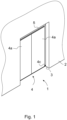
- FIG. 1 presents in a simplified and diagrammatic oblique top view an installed elevator landing door assembly according to the invention.
- the landing door 1 with its top track 5, landing door unit 4 comprising advantageously a frame, two door panels 4a, and a door sill 4c has been installed into a base door opening 3 formed in a wall 2 of the building, which base door opening 3 opens to an elevator shaft.
- the base door opening 3 comprises an upper edge, two side edges and a lower edge.
- the type of the landing door in Figure 1 is such that the door panels 4a open by separation from each other toward opposite directions and close toward each other by moving opposite directions.
- the landing door 1 opens from the middle.
- the two-part landing door could open from one side as is presented later in figures 7-10 .
- the landing door installation is not yet complete, so the top track 5 is seen above the door panels 4a, and also a part of the doorsill 4c is seen.
- the structure of the landing door 1 does not necessarily cover the whole base door opening 3, but the final covering is implemented with covering plates or corresponding structures that are fitted to close all the gaps between edges of the base door opening 3 and the door panels 4a and other door components at both the sides of the base door opening 3 and above it.
- the base door opening 3 and its gaps can be covered, for example during the installation time, with a protection wall, such as a hard gypsum panel.
- a protection wall such as a hard gypsum panel.
- the hard gypsum panel can be enforced.
- Figure 2 presents in a simplified and diagrammatic top view an elevator landing door base opening 3 with the visible walls cross-sectioned just above the floor level 8. Only a part of elevator shaft 6 and its sidewalls 6a is seen in figure 2 but the front wall 7 of the elevator shaft is completely seen.
- a pair of lower fixing elements 9 for the elevator landing door unit 4 is fastened onto the floor 8 at the base door opening 3.
- the lower fixing elements 9 extent downwards in the vertical level of the front wall 7 of the elevator shaft 6.
- FIG. 3 presents in a simplified and diagrammatic oblique top view the lower fixing element 9 of the landing door assembly according to the invention.
- the lower fixing element 9 comprises a frame 9a and a receiving part 9b for receiving counter parts of the lower part of the landing door unit 4 to be installed to the base opening 3.
- the frame 9a is advantageously an L-shape element with a first flange 10 and a second flange 11 that are substantially perpendicular to each other.
- the frame 9a comprises fastening holes 12 through which the lower fixing element 9 is fastened at its place onto the edge of the floor 8 at the base door opening 3.
- the fastening can be made with fastening elements such as screws either onto the floor 8 or onto the front wall 7 of the elevator shaft 6, or onto the both.
- the first flange 10 is advantageously a horizontal flange and is equipped with the receiving part 9b whose cross-section is like a C-profile, which has a hollow interior, and where a longitudinal slot 13 is upward.
- the longitudinal slot 13 is directed horizontally towards the elevator shaft 6, and is perpendicular to the width of the base opening 3.
- FIG. 4 presents in a simplified and diagrammatic oblique top view an upper fixing element 14 of the landing door assembly according to the invention.
- the upper fixing element 14 comprises a frame 14a and a receiving part 14b for receiving counter parts of the upper edge of the landing door unit 4 to be installed to the base opening 3.
- the frame 14a is advantageously an L-shape element with a first flange 15 and a second flange 16 that are substantially perpendicular to each other.
- the frame 14a comprises fastening holes 17 through which the upper fixing element 14 is fastened at its place onto the upper edge of the base door opening 3.
- the fastening can be made with fastening elements such as screws onto the upper edge of the base door opening 3.
- the first flange 15 of the upper fixing element 14 is advantageously a vertical flange and is equipped with the receiving part 14b whose cross-section is like a C-profile which has a hollow interior, and where the longitudinal slot 18 is vertical.
- the longitudinal slot 18 is vertical and opens perpendicularly away from the elevator shaft 6 towards the lobby of the floor level.
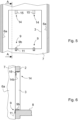
- Figures 5 and 6 present in a simplified and diagrammatic view the landing door base opening 3 equipped with the fixing elements 9 and 14 according to the invention.
- the landing door base opening 3 is seen from the elevator shaft 6, and in figure 6 the landing door base opening 3 is seen in a cross-section A-A of figure 5 .
- the lower fixing elements 9 are fastened into their place on the edge of the floor of the floor level 8 so that the first flange 10 lies on the floor 8 and the second flange 11 is fastened with fastening elements to the vertical front wall 7 of the elevator shaft.
- the fastening elements are fastening screws or bolts.
- the receiving part 9b is preferably inside the thickness of the wall 2 in a horizontal position and the longitudinal slot 13 is directed horizontally towards the elevator shaft 6, and is perpendicular to the width of the door base opening 3, as is described above.
- the landing door assembly according to the invention comprises two similar lower fixing elements 9 that are situated horizontally apart from each other and each in its own vertical line with the other corresponding lower fixing elements 9 of the other floors of the building.
- the upper fixing elements 14 are fastened into their place on the upper edge of the door base opening 3 so that the first flange 15 extends downwards and the second flange 16 is fastened with fastening elements to the horizontal upper edge of the door base opening 3, preferably inside the thickness of the wall 2.
- the fastening elements are fastening screws or bolts.
- the receiving part 14b is preferably inside the thickness of the wall 2 in a vertical position and the longitudinal slot 18 is open away from the elevator shaft 6 towards the lobby of floor level 8, as is described above.
- the landing door assembly according to the invention comprises two similar upper fixing elements 14 that are situated horizontally apart from each other and each in its own vertical line with the other corresponding upper fixing elements 14 of the other floors of the building.
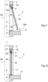
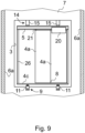
- Figures 7 - 9 present in a simplified and diagrammatic view the installation of the elevator landing door unit 4 into the elevator landing door base opening 3.
- the elevator landing door unit 4 also comprises a frame that is not presented in the figures.
- Figures 7 and 8 are shown in the cross-section A-A of figure 5 , and figure 9 is seen from the elevator shaft 6.
- the fastening of the landing door unit 4 has been just started, and in figures 8 and 9 the landing door unit 4 has been fastened at its place inside the landing door base opening 3 within the thickness of the wall 2.
- Figures 7 - 9 show such an embodiment of the invention where the landing door opens to one side.
- the door panels 4a are suspended from the top track 5 in different sides of the top track 5 so that the first door panel 4a is suspended by a first supporter 20 in the first side of the top track 5 and the second door panel 4a is suspended by a second supporter 21 in the second side of the top track 5.
- the landing door unit 4 comprises upper counter parts 19 at its upper edge and lower counter parts 19a at its lower edge.
- the number of upper and lower counterparts 19, 19a is the same as the number of upper and lower fixing elements 9, 14 in one elevator landing door base opening 3.
- the landing door unit 4 comprises two upper counter parts 19 and two lower counter parts 19a.
- the horizontal distance between the upper counter parts 19 is the same as the horizontal distance between the upper fixing elements 14, and the horizontal distance between the lower counter parts 19a is the same as the horizontal distance between the lower fixing elements 9.
- the landing door unit 4 that is prefabricated in a factory, is installed to the base door base opening 3 by guiding the upper counter parts 19 first from under to the vertical slots 18 of the upper fixing elements 14.
- the landing door unit 4 is pushed upward and preferably simultaneously its lower edge is turned towards the elevator shaft 6.
- the turning is continued until the lower counter parts 19a reach the lower fixing elements 9.
- the lower counter parts 19a are guided to the horizontal slots 13 of the lower fixing elements 9 and the turning is continued until the landing door unit 4 is substantially in a vertical position in its place. After that the final position of the landing door unit 4 is adjusted in the fixing elements 9 and 14.
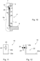
- Figure 10 presents in a simplified and diagrammatic view the elevator landing door base opening 3 according to Fig. 5 in the cross-section A-A, and in a situation where the landing door unit 4 has been fastened at its place.
- the landing door unit 4 is fastened totally inside the elevator shaft 6 and for that reason the fixing elements 9 and 14 differ in their structures from the fixing elements 9 and 14 presented in figures 2-9 .
- the only decisive difference is that the receiving part 9b of the lower fixing elements 9 extends inside the elevator shaft 6 and the receiving part 14b of the upper fixing elements 14 is totally inside the elevator shaft 6.
- the landing door unit 4 itself can be similar to the landing door unit 4 presented in figures 7-9 .
- Figures 11 and 12 present an upper counter element 19 to be fitted into the upper fixing element 14 of the elevator landing door unit 4.
- the upper counter element 19 comprises an L-shaped frame 22 with a first flange 22a and a second flange 22b which flanges are perpendicular to each other.
- the upper counter element 19 is fastened to the upper edge of the landing door unit 4 through the first flange 22a with fastening elements, such as screws.
- the second flange 22b is preferably in a vertical position and comprises a longitudinal vertical slot 25 for adjusting the height position of the landing door unit 4.
- the slot 25 is equipped with a bolt 24 that is fastened with screw threads to a tightening element 23, such as a tightening plate.
- the width of the tightening element 23 is smaller than the width of interior of the C-profile of the receiving part 14b, and the diameter of the bolt 24 is smaller than the width of the slot 18 of the receiving part 14b. Therefore, when installing the landing door unit 4 the tightening element 23 can be placed inside the C-profile of the receiving part 14b in such a way that the bolt 24 is guided by the slot 18. When the landing door unit 4 is adjusted to its correct height position the tightening element 23 is tightened by the help of the bolt 24 to the receiving part 14b so that the landing door unit 4 remains its correct height position.
- the structure of the lower counter parts 19a can be substantially the same as the structure of the upper counter parts 19 but may also be different.
- the landing door assembly can be safely installed from the landing side. This means that all the installation work can be done from the side of the floor level 8 and there is no need to go to the elevator shaft 6.
Landscapes
- Engineering & Computer Science (AREA)
- Mechanical Engineering (AREA)
- Elevator Door Apparatuses (AREA)
Claims (11)
- Aufzugs-Schachttürbaugruppe, wobei die Schachttürbaugruppe mindestens eine Schachttüreinheit (4) umfasst, die an einer Schachttürbasisöffnung (3) mit einer oberen Kante, zwei Seitenkanten und einer unteren Kante zu montieren ist, wobei die Schachttüreinheit (4) mindestens eine obere Schiene (5) und ein oder mehrere Türpaneele (4a) aufweist, die an der oberen Schiene (5) über ein oder mehrere Stützelemente (20, 21) aufgehängt sind, ferner eine Türschwelle (4c), wobei die Baugruppe Befestigungselemente (9, 14) in der Schachttür-Basisöffnung (3) umfasst, die mit Aufnahmeteilen (9b, 14b) zur Befestigung der Schachttüreinheit (4) ausgestattet sind,
dadurch gekennzeichnet, dass das Aufnahmeteil (14b) eines oberen Befestigungselements (14) einen hohlen Innenraum und einen vertikalen Schlitz (18) zur Aufnahme eines oberen Gegenstücks (19) der Schachttüreinheit (4) umfasst und dass das Aufnahmeteil (9b) eines unteren Befestigungselements (9) einen hohlen Innenraum und einen horizontalen Schlitz (13) zur Aufnahme eines unteren Gegenstücks (19a) der Schachttüreinheit (4) umfasst. - Aufzugs-Schachttürbaugruppe nach Anspruch 1, dadurch gekennzeichnet, dass die Baugruppe mindestens zwei untere Befestigungselemente (9), die in der Unterkante der Schachttürgrundöffnung (3) befestigt sind, und mindestens zwei obere Befestigungselemente (14), die in der Oberkante der Schachttürgrundöffnung (3) befestigt sind, umfasst.
- Aufzugs-Schachttürbaugruppe nach Anspruch 2, dadurch gekennzeichnet, dass die Schachttüreinheit (4) obere Gegenstücke (19), die an den oberen Befestigungselementen (14) zu befestigen sind, und untere Gegenstücke (19a), die an den unteren Befestigungselementen (9) zu befestigen sind, umfasst.
- Aufzugs-Schachttürbaugruppe nach einem der vorstehenden Ansprüche, dadurch gekennzeichnet, dass das obere Gegenstück (19) einen Einstellmechanismus (23, 24, 25) für die Höheneinstellung der Schachttüreinheit (4) umfasst.
- Aufzugs-Schachttürbaugruppe nach einem der vorstehenden Ansprüche, dadurch gekennzeichnet, dass das (die) untere(n) Befestigungselement(e) (9) und das (die) obere(n) Befestigungselement(e) (14) verschiedener Stockwerke in zwei vertikalen Linien ausgerichtet sind.
- Aufzugs-Schachttürbaugruppe nach einem der vorstehenden Ansprüche, dadurch gekennzeichnet, dass die in der Schachttürsockelöffnung (3) eingebaute Schachttür (1) eine Schutzabdeckung, wie z.B. eine Hartgipsplatte, aufweist.
- Verfahren zum Installieren einer Aufzugsschachttürbaugruppe nach Anspruch 1, wobei die Schachttürbaugruppe mindestens eine Schachttüreinheit (4) umfasst, die an einer Schachttürbasisöffnung (3) mit einer Oberkante, zwei Seitenkanten und einer Unterkante montiert wird, wobei die Schachttüreinheit (4) mindestens eine obere Schiene (5) und eine oder mehrere Türpaneele (4a), die an der oberen Schiene (5) durch ein oder mehrere Stützelemente (20, 21) aufgehängt sind, und eine Türschwelle (4c) umfasst, wobei die Schachttürbasisöffnung (3) mit Befestigungselementen (9, 14) ausgestattet ist, die Aufnahmeteile (9b, 14b) zur Befestigung der Schachttüreinheit (4) aufweist, und die Schachttüreinheit (4) mit den Aufnahmeteilen (9b, 14b) von der Schachtseite her verbunden und an den Aufnahmeteilen (9b, 14b) befestigt ist, dadurch gekennzeichnet, dass zunächst ein oberer Rand der Schachttüreinheit (4) mit den Aufnahmeteilen (14b) von oberen Befestigungselementen (14) verbunden wird und danach ein unterer Teil der Schachttüreinheit (4) zu einem Aufzugsschacht (6) und zu unteren Befestigungselementen (9) gedreht und mit den Aufnahmeteilen (9b) der unteren Befestigungselemente (9) verbunden wird.
- Verfahren zum Einbau einer Aufzugsschachttür nach Anspruch 7, dadurch gekennzeichnet, dass beim Verbinden mit den Aufnahmeteilen (14b) der oberen Befestigungselemente (14) ein Verstellmechanismus (23, 24, 25) von oberen Gegenstücken (19) in hohle Innenräume und in Schlitze (18) der Aufnahmeteile (14b) eingesetzt wird.
- Verfahren zum Einbau einer Aufzugsschachttür nach Anspruch 8, dadurch gekennzeichnet, dass nach dem Einsetzen des Einstellmechanismus (23, 24, 25) des oberen Gegenstücks (19) in den hohlen Innenraum und in den Schlitz (18) des Aufnahmeteils (14b) die Schachttüreinheit (4) nach oben geschoben wird und der untere Teil der Schachttüreinheit (4) zum Aufzugsschacht (6) und zum unteren Befestigungselement (9) gedreht wird, um ein unteres Gegenstück (19a) mit dem Aufnahmeteil (9b) des unteren Befestigungselements (9) zu verbinden und zu befestigen.
- Verfahren zum Einbau einer Aufzugsschachttür nach Anspruch 9, dadurch gekennzeichnet, dass nach dem Verbinden der Gegenstücke (19, 19a) der Schachttüreinheit (4) mit den Befestigungselementen (9, 14) die Höhe der Schachttüreinheit (4) eingestellt und die Schachttüreinheit (4) an ihrem endgültigen Ort befestigt wird.
- Verfahren zum Einbau einer Aufzugsschachttür nach Anspruch 10, dadurch gekennzeichnet, dass nach der Befestigung der Schachttüreinheit (4) die Schachttürbodenöffnung (3) durch eine Schutzwand abgedeckt wird.
Applications Claiming Priority (1)
| Application Number | Priority Date | Filing Date | Title |
|---|---|---|---|
| PCT/FI2018/050146 WO2019166685A1 (en) | 2018-02-28 | 2018-02-28 | Elevator landing door assembly and its installation method |
Publications (3)
| Publication Number | Publication Date |
|---|---|
| EP3759041A1 EP3759041A1 (de) | 2021-01-06 |
| EP3759041A4 EP3759041A4 (de) | 2021-09-08 |
| EP3759041B1 true EP3759041B1 (de) | 2024-10-16 |
Family
ID=67805164
Family Applications (1)
| Application Number | Title | Priority Date | Filing Date |
|---|---|---|---|
| EP18908116.9A Active EP3759041B1 (de) | 2018-02-28 | 2018-02-28 | Aufzugsschachttüranordnung und installationsverfahren dafür |
Country Status (4)
| Country | Link |
|---|---|
| US (1) | US11498812B2 (de) |
| EP (1) | EP3759041B1 (de) |
| CN (1) | CN111683890B (de) |
| WO (1) | WO2019166685A1 (de) |
Families Citing this family (4)
| Publication number | Priority date | Publication date | Assignee | Title |
|---|---|---|---|---|
| WO2022117496A1 (de) * | 2020-12-01 | 2022-06-09 | Inventio Ag | Aufzugsystem mit einem montagebügel |
| WO2022233804A1 (de) * | 2021-05-05 | 2022-11-10 | Inventio Ag | Verfahren zur installation einer aufzuganlage |
| CN114104926B (zh) * | 2021-11-23 | 2023-06-02 | 上海三菱电梯有限公司 | 层站组件定位工装及电梯层门组件安装方法 |
| JP7685165B1 (ja) * | 2024-03-04 | 2025-05-29 | フジテック株式会社 | エレベータの乗場構造 |
Citations (1)
| Publication number | Priority date | Publication date | Assignee | Title |
|---|---|---|---|---|
| WO2000030966A2 (en) * | 1998-11-20 | 2000-06-02 | Kone Corporation | Hold block |
Family Cites Families (34)
| Publication number | Priority date | Publication date | Assignee | Title |
|---|---|---|---|---|
| US3601938A (en) * | 1970-01-16 | 1971-08-31 | Charles M Loomis | Universal elevator shaft entrance construction |
| US3741351A (en) * | 1971-03-05 | 1973-06-26 | Westinghouse Electric Corp | Integrated elevator construction |
| US3740907A (en) * | 1971-08-27 | 1973-06-26 | C Loomis | Gauge frame for elevator shaft entrance opening |
| US3771268A (en) * | 1972-08-30 | 1973-11-13 | C Loomis | Pre-assembled unitarily-insertable hanger-attached elevator shaft entrance construction |
| US3984952A (en) * | 1975-11-28 | 1976-10-12 | Loomis Charles M | Gauge panel structure for elevator shaft rough entrance opening |
| US4099599A (en) * | 1977-02-01 | 1978-07-11 | Westinghouse Electric Corp. | Method and apparatus for fastening a door panel to a door operator mounted on an elevator car |
| CH649125A5 (fr) * | 1982-08-03 | 1985-04-30 | Inventio Ag | Huisserie de porte paliere d'ascenseur. |
| FI86625C (fi) * | 1990-09-14 | 1992-09-25 | Kone Oy | Foerfarande foer montering av stannplansdoerrar till hiss. |
| ES2083012T3 (es) * | 1991-05-14 | 1996-04-01 | Inventio Ag | Ascensor. |
| EP0606508B1 (de) * | 1993-01-14 | 1999-04-07 | Inventio Ag | Verfahren und Einrichtung für den Schachttüreinbau bei Aufzügen |
| US5701973A (en) * | 1995-06-23 | 1997-12-30 | Otis Elevator Company | Linear belt door operator |
| US5673770A (en) * | 1996-01-25 | 1997-10-07 | Friedman; Harold S. | Sliding door assembly for an elevator and method of installing same |
| US6145630A (en) * | 1996-01-25 | 2000-11-14 | Friedman; Harold S. | Sliding elevator-door assembly and method of installation |
| JPH09240971A (ja) * | 1996-03-07 | 1997-09-16 | Toshiba Corp | エレベータのドア装置 |
| FI981992A0 (fi) * | 1997-11-06 | 1998-09-15 | Kone Corp | Tason oven asennusmenetelmä ja vastaava asennusjärjestelmä |
| JPH11278780A (ja) * | 1998-03-24 | 1999-10-12 | Hitachi Building Systems Co Ltd | エレベータ出入口一体搬入構造 |
| WO2000032509A1 (en) * | 1998-11-13 | 2000-06-08 | Kone Corporation | Elevator landing door structure |
| FI107251B (fi) * | 1998-11-13 | 2001-06-29 | Kone Corp | Hissin tason ovirakenne |
| JP2001058783A (ja) * | 1999-07-12 | 2001-03-06 | Inventio Ag | 昇降路ドア付きエレベータ設備 |
| US6938380B2 (en) * | 2001-12-14 | 2005-09-06 | Harold S. Friedman | Elevator entrance sill structure and installation method |
| US7322555B2 (en) * | 2005-01-10 | 2008-01-29 | The Peelle Company Ltd. | Track jack system |
| JP2006213420A (ja) * | 2005-02-01 | 2006-08-17 | Toshiba Elevator Co Ltd | 免震建物用エレベータの乗場ドア設置構造 |
| JP4861697B2 (ja) * | 2005-12-21 | 2012-01-25 | 東芝エレベータ株式会社 | エレベータのドア装置 |
| KR100742315B1 (ko) * | 2007-01-25 | 2007-07-24 | (주)두성엔티 | 엘리베이터 도어의 이탈 방지 장치 |
| JP5003539B2 (ja) * | 2008-03-10 | 2012-08-15 | 三菱電機ビルテクノサービス株式会社 | エレベータの据付方法、並びに、それに用いられる据付治具及び据付治具の製造方法 |
| EP2374747B1 (de) * | 2010-04-12 | 2013-11-13 | Eraldo Cazzaniga | System von Komponententeilen eines Aufzugsystems an den Boden des Aufzugschachts und zugehöriges Montageverfahren |
| CN101837913B (zh) * | 2010-05-18 | 2012-05-30 | 广东省特种设备检测院 | 用于电梯性能检测系统的门固定装置 |
| JP5697166B2 (ja) * | 2012-05-29 | 2015-04-08 | 東芝エレベータ株式会社 | エレベータのホールドア装置 |
| FI125326B (fi) * | 2013-10-02 | 2015-08-31 | Kone Corp | Hissin ovijärjestely |
| EP3031768B1 (de) * | 2014-12-12 | 2017-08-16 | KONE Corporation | Aufzugsschachttüranordnung |
| KR101806017B1 (ko) * | 2016-04-12 | 2017-12-07 | 박정호 | 승강기도어 이탈방지장치 |
| CN109071176A (zh) * | 2016-04-19 | 2018-12-21 | 通力股份公司 | 电梯门结构中的装置 |
| JP6537732B2 (ja) * | 2016-07-14 | 2019-07-03 | 三菱電機株式会社 | エレベータおよびエレベータのリニューアル方法 |
| WO2018029742A1 (ja) * | 2016-08-08 | 2018-02-15 | 三菱電機株式会社 | エレベータのかご |
-
2018
- 2018-02-28 CN CN201880088847.6A patent/CN111683890B/zh active Active
- 2018-02-28 WO PCT/FI2018/050146 patent/WO2019166685A1/en not_active Ceased
- 2018-02-28 EP EP18908116.9A patent/EP3759041B1/de active Active
-
2020
- 2020-07-17 US US16/931,873 patent/US11498812B2/en active Active
Patent Citations (1)
| Publication number | Priority date | Publication date | Assignee | Title |
|---|---|---|---|---|
| WO2000030966A2 (en) * | 1998-11-20 | 2000-06-02 | Kone Corporation | Hold block |
Also Published As
| Publication number | Publication date |
|---|---|
| WO2019166685A1 (en) | 2019-09-06 |
| CN111683890B (zh) | 2023-04-04 |
| US20200346898A1 (en) | 2020-11-05 |
| CN111683890A (zh) | 2020-09-18 |
| EP3759041A1 (de) | 2021-01-06 |
| US11498812B2 (en) | 2022-11-15 |
| EP3759041A4 (de) | 2021-09-08 |
Similar Documents
| Publication | Publication Date | Title |
|---|---|---|
| US11498812B2 (en) | Elevator landing door assembly and its installation method | |
| US6422352B1 (en) | Procedure and apparatus for the installation of an elevator | |
| US5445244A (en) | System for forming the jambs for the landing doors of an elevator | |
| US5479754A (en) | Method and apparatus for installing an elevator shaft door | |
| EP1812328B1 (de) | Einbau von führungsschiene in einem aufzugssysteme | |
| EP2774887A1 (de) | Türschwelleneinheit und Verfahren für eine Aufzugfahrschachttüreinheit | |
| JP2008265939A (ja) | エレベータの乗り場敷居装置 | |
| JP2912276B2 (ja) | 鋼製建具の設置方法及びそれに使用する設置金具 | |
| HK40033079A (en) | Elevator landing door assembly and its installation method | |
| HK40033079B (en) | Elevator landing door assembly and its installation method | |
| JP5388459B2 (ja) | エレベータの乗場ドア装置、及びエレベータの乗場ドア装置の設置方法 | |
| EP3392431A1 (de) | Befestigungsvorrichtung zur installation eines fensters und einer tür und installationssystem und -verfahren für fenster und türen | |
| WO2010089590A1 (en) | Door frame assembly and method of installation of doors | |
| EP2706167B1 (de) | Wandkonsole | |
| JP2010184755A (ja) | エレベータの乗場ユニット | |
| JP2006044843A (ja) | 昇降路用作業台足場 | |
| US20060179745A1 (en) | Method of building a building | |
| WO2000012836A2 (en) | A curtain wall system | |
| JPH089469B2 (ja) | 乗場出入口装置の取付方法 | |
| JP5146076B2 (ja) | エレベータの乗場装置 | |
| KR20070045149A (ko) | 엘리베이터 샤프트 밀폐구조물 | |
| HK1011333B (en) | Method and apparatus for elevator hoistway door installation | |
| HK1242284A1 (en) | Elevator system door frame that supports guide rails | |
| HK1242284A (en) | Elevator system door frame that supports guide rails | |
| HK1167253A (en) | Elevator system door frame that supports guider rails |
Legal Events
| Date | Code | Title | Description |
|---|---|---|---|
| STAA | Information on the status of an ep patent application or granted ep patent |
Free format text: STATUS: THE INTERNATIONAL PUBLICATION HAS BEEN MADE |
|
| PUAI | Public reference made under article 153(3) epc to a published international application that has entered the european phase |
Free format text: ORIGINAL CODE: 0009012 |
|
| STAA | Information on the status of an ep patent application or granted ep patent |
Free format text: STATUS: REQUEST FOR EXAMINATION WAS MADE |
|
| 17P | Request for examination filed |
Effective date: 20200706 |
|
| AK | Designated contracting states |
Kind code of ref document: A1 Designated state(s): AL AT BE BG CH CY CZ DE DK EE ES FI FR GB GR HR HU IE IS IT LI LT LU LV MC MK MT NL NO PL PT RO RS SE SI SK SM TR |
|
| AX | Request for extension of the european patent |
Extension state: BA ME |
|
| DAV | Request for validation of the european patent (deleted) | ||
| DAX | Request for extension of the european patent (deleted) | ||
| A4 | Supplementary search report drawn up and despatched |
Effective date: 20210809 |
|
| RIC1 | Information provided on ipc code assigned before grant |
Ipc: E05D 15/06 20060101ALI20210803BHEP Ipc: B66B 13/00 20060101ALI20210803BHEP Ipc: B66B 13/30 20060101AFI20210803BHEP |
|
| STAA | Information on the status of an ep patent application or granted ep patent |
Free format text: STATUS: EXAMINATION IS IN PROGRESS |
|
| 17Q | First examination report despatched |
Effective date: 20230310 |
|
| P01 | Opt-out of the competence of the unified patent court (upc) registered |
Effective date: 20230525 |
|
| GRAP | Despatch of communication of intention to grant a patent |
Free format text: ORIGINAL CODE: EPIDOSNIGR1 |
|
| STAA | Information on the status of an ep patent application or granted ep patent |
Free format text: STATUS: GRANT OF PATENT IS INTENDED |
|
| INTG | Intention to grant announced |
Effective date: 20240703 |
|
| GRAS | Grant fee paid |
Free format text: ORIGINAL CODE: EPIDOSNIGR3 |
|
| GRAA | (expected) grant |
Free format text: ORIGINAL CODE: 0009210 |
|
| STAA | Information on the status of an ep patent application or granted ep patent |
Free format text: STATUS: THE PATENT HAS BEEN GRANTED |
|
| AK | Designated contracting states |
Kind code of ref document: B1 Designated state(s): AL AT BE BG CH CY CZ DE DK EE ES FI FR GB GR HR HU IE IS IT LI LT LU LV MC MK MT NL NO PL PT RO RS SE SI SK SM TR |
|
| REG | Reference to a national code |
Ref country code: GB Ref legal event code: FG4D |
|
| REG | Reference to a national code |
Ref country code: CH Ref legal event code: EP Ref country code: DE Ref legal event code: R096 Ref document number: 602018075639 Country of ref document: DE |
|
| REG | Reference to a national code |
Ref country code: IE Ref legal event code: FG4D |
|
| REG | Reference to a national code |
Ref country code: LT Ref legal event code: MG9D |
|
| REG | Reference to a national code |
Ref country code: NL Ref legal event code: MP Effective date: 20241016 |
|
| REG | Reference to a national code |
Ref country code: AT Ref legal event code: MK05 Ref document number: 1732787 Country of ref document: AT Kind code of ref document: T Effective date: 20241016 |
|
| PG25 | Lapsed in a contracting state [announced via postgrant information from national office to epo] |
Ref country code: NL Free format text: LAPSE BECAUSE OF FAILURE TO SUBMIT A TRANSLATION OF THE DESCRIPTION OR TO PAY THE FEE WITHIN THE PRESCRIBED TIME-LIMIT Effective date: 20241016 |
|
| PG25 | Lapsed in a contracting state [announced via postgrant information from national office to epo] |
Ref country code: NL Free format text: LAPSE BECAUSE OF FAILURE TO SUBMIT A TRANSLATION OF THE DESCRIPTION OR TO PAY THE FEE WITHIN THE PRESCRIBED TIME-LIMIT Effective date: 20241016 |
|
| PG25 | Lapsed in a contracting state [announced via postgrant information from national office to epo] |
Ref country code: IS Free format text: LAPSE BECAUSE OF FAILURE TO SUBMIT A TRANSLATION OF THE DESCRIPTION OR TO PAY THE FEE WITHIN THE PRESCRIBED TIME-LIMIT Effective date: 20250216 Ref country code: PT Free format text: LAPSE BECAUSE OF FAILURE TO SUBMIT A TRANSLATION OF THE DESCRIPTION OR TO PAY THE FEE WITHIN THE PRESCRIBED TIME-LIMIT Effective date: 20250217 Ref country code: HR Free format text: LAPSE BECAUSE OF FAILURE TO SUBMIT A TRANSLATION OF THE DESCRIPTION OR TO PAY THE FEE WITHIN THE PRESCRIBED TIME-LIMIT Effective date: 20241016 |
|
| PGFP | Annual fee paid to national office [announced via postgrant information from national office to epo] |
Ref country code: DE Payment date: 20250218 Year of fee payment: 8 |
|
| PG25 | Lapsed in a contracting state [announced via postgrant information from national office to epo] |
Ref country code: FI Free format text: LAPSE BECAUSE OF FAILURE TO SUBMIT A TRANSLATION OF THE DESCRIPTION OR TO PAY THE FEE WITHIN THE PRESCRIBED TIME-LIMIT Effective date: 20241016 |
|
| PG25 | Lapsed in a contracting state [announced via postgrant information from national office to epo] |
Ref country code: BG Free format text: LAPSE BECAUSE OF FAILURE TO SUBMIT A TRANSLATION OF THE DESCRIPTION OR TO PAY THE FEE WITHIN THE PRESCRIBED TIME-LIMIT Effective date: 20241016 |
|
| PG25 | Lapsed in a contracting state [announced via postgrant information from national office to epo] |
Ref country code: ES Free format text: LAPSE BECAUSE OF FAILURE TO SUBMIT A TRANSLATION OF THE DESCRIPTION OR TO PAY THE FEE WITHIN THE PRESCRIBED TIME-LIMIT Effective date: 20241016 |
|
| PG25 | Lapsed in a contracting state [announced via postgrant information from national office to epo] |
Ref country code: NO Free format text: LAPSE BECAUSE OF FAILURE TO SUBMIT A TRANSLATION OF THE DESCRIPTION OR TO PAY THE FEE WITHIN THE PRESCRIBED TIME-LIMIT Effective date: 20250116 |
|
| PG25 | Lapsed in a contracting state [announced via postgrant information from national office to epo] |
Ref country code: LV Free format text: LAPSE BECAUSE OF FAILURE TO SUBMIT A TRANSLATION OF THE DESCRIPTION OR TO PAY THE FEE WITHIN THE PRESCRIBED TIME-LIMIT Effective date: 20241016 Ref country code: GR Free format text: LAPSE BECAUSE OF FAILURE TO SUBMIT A TRANSLATION OF THE DESCRIPTION OR TO PAY THE FEE WITHIN THE PRESCRIBED TIME-LIMIT Effective date: 20250117 Ref country code: AT Free format text: LAPSE BECAUSE OF FAILURE TO SUBMIT A TRANSLATION OF THE DESCRIPTION OR TO PAY THE FEE WITHIN THE PRESCRIBED TIME-LIMIT Effective date: 20241016 |
|
| PG25 | Lapsed in a contracting state [announced via postgrant information from national office to epo] |
Ref country code: PL Free format text: LAPSE BECAUSE OF FAILURE TO SUBMIT A TRANSLATION OF THE DESCRIPTION OR TO PAY THE FEE WITHIN THE PRESCRIBED TIME-LIMIT Effective date: 20241016 |
|
| PGFP | Annual fee paid to national office [announced via postgrant information from national office to epo] |
Ref country code: FR Payment date: 20250224 Year of fee payment: 8 |
|
| PGFP | Annual fee paid to national office [announced via postgrant information from national office to epo] |
Ref country code: GB Payment date: 20250220 Year of fee payment: 8 |
|
| PG25 | Lapsed in a contracting state [announced via postgrant information from national office to epo] |
Ref country code: RS Free format text: LAPSE BECAUSE OF FAILURE TO SUBMIT A TRANSLATION OF THE DESCRIPTION OR TO PAY THE FEE WITHIN THE PRESCRIBED TIME-LIMIT Effective date: 20250116 |
|
| PG25 | Lapsed in a contracting state [announced via postgrant information from national office to epo] |
Ref country code: SM Free format text: LAPSE BECAUSE OF FAILURE TO SUBMIT A TRANSLATION OF THE DESCRIPTION OR TO PAY THE FEE WITHIN THE PRESCRIBED TIME-LIMIT Effective date: 20241016 |
|
| PG25 | Lapsed in a contracting state [announced via postgrant information from national office to epo] |
Ref country code: DK Free format text: LAPSE BECAUSE OF FAILURE TO SUBMIT A TRANSLATION OF THE DESCRIPTION OR TO PAY THE FEE WITHIN THE PRESCRIBED TIME-LIMIT Effective date: 20241016 |
|
| REG | Reference to a national code |
Ref country code: DE Ref legal event code: R097 Ref document number: 602018075639 Country of ref document: DE |
|
| PG25 | Lapsed in a contracting state [announced via postgrant information from national office to epo] |
Ref country code: EE Free format text: LAPSE BECAUSE OF FAILURE TO SUBMIT A TRANSLATION OF THE DESCRIPTION OR TO PAY THE FEE WITHIN THE PRESCRIBED TIME-LIMIT Effective date: 20241016 |
|
| PG25 | Lapsed in a contracting state [announced via postgrant information from national office to epo] |
Ref country code: RO Free format text: LAPSE BECAUSE OF FAILURE TO SUBMIT A TRANSLATION OF THE DESCRIPTION OR TO PAY THE FEE WITHIN THE PRESCRIBED TIME-LIMIT Effective date: 20241016 |
|
| PG25 | Lapsed in a contracting state [announced via postgrant information from national office to epo] |
Ref country code: SK Free format text: LAPSE BECAUSE OF FAILURE TO SUBMIT A TRANSLATION OF THE DESCRIPTION OR TO PAY THE FEE WITHIN THE PRESCRIBED TIME-LIMIT Effective date: 20241016 |
|
| PG25 | Lapsed in a contracting state [announced via postgrant information from national office to epo] |
Ref country code: CZ Free format text: LAPSE BECAUSE OF FAILURE TO SUBMIT A TRANSLATION OF THE DESCRIPTION OR TO PAY THE FEE WITHIN THE PRESCRIBED TIME-LIMIT Effective date: 20241016 |
|
| PG25 | Lapsed in a contracting state [announced via postgrant information from national office to epo] |
Ref country code: IT Free format text: LAPSE BECAUSE OF FAILURE TO SUBMIT A TRANSLATION OF THE DESCRIPTION OR TO PAY THE FEE WITHIN THE PRESCRIBED TIME-LIMIT Effective date: 20241016 |
|
| PLBE | No opposition filed within time limit |
Free format text: ORIGINAL CODE: 0009261 |
|
| STAA | Information on the status of an ep patent application or granted ep patent |
Free format text: STATUS: NO OPPOSITION FILED WITHIN TIME LIMIT |
|
| PG25 | Lapsed in a contracting state [announced via postgrant information from national office to epo] |
Ref country code: SE Free format text: LAPSE BECAUSE OF FAILURE TO SUBMIT A TRANSLATION OF THE DESCRIPTION OR TO PAY THE FEE WITHIN THE PRESCRIBED TIME-LIMIT Effective date: 20241016 |
|
| PG25 | Lapsed in a contracting state [announced via postgrant information from national office to epo] |
Ref country code: MC Free format text: LAPSE BECAUSE OF FAILURE TO SUBMIT A TRANSLATION OF THE DESCRIPTION OR TO PAY THE FEE WITHIN THE PRESCRIBED TIME-LIMIT Effective date: 20241016 |
|
| 26N | No opposition filed |
Effective date: 20250717 |
|
| REG | Reference to a national code |
Ref country code: CH Ref legal event code: PL |
|
| PG25 | Lapsed in a contracting state [announced via postgrant information from national office to epo] |
Ref country code: LU Free format text: LAPSE BECAUSE OF NON-PAYMENT OF DUE FEES Effective date: 20250228 |
|
| PG25 | Lapsed in a contracting state [announced via postgrant information from national office to epo] |
Ref country code: CH Free format text: LAPSE BECAUSE OF NON-PAYMENT OF DUE FEES Effective date: 20250228 |