EP3758105A1 - Verfahren zur lithiierung von elektroden von lithiumbasierten elektrischen energiespeicherelementen sowie mit dem verfahren hergestelltes elektrisches energiespeicherelement - Google Patents
Verfahren zur lithiierung von elektroden von lithiumbasierten elektrischen energiespeicherelementen sowie mit dem verfahren hergestelltes elektrisches energiespeicherelement Download PDFInfo
- Publication number
- EP3758105A1 EP3758105A1 EP20180244.4A EP20180244A EP3758105A1 EP 3758105 A1 EP3758105 A1 EP 3758105A1 EP 20180244 A EP20180244 A EP 20180244A EP 3758105 A1 EP3758105 A1 EP 3758105A1
- Authority
- EP
- European Patent Office
- Prior art keywords
- lithium
- electrode
- layer
- energy storage
- electrical energy
- Prior art date
- Legal status (The legal status is an assumption and is not a legal conclusion. Google has not performed a legal analysis and makes no representation as to the accuracy of the status listed.)
- Granted
Links
Images

Classifications
-
- H—ELECTRICITY
- H01—ELECTRIC ELEMENTS
- H01M—PROCESSES OR MEANS, e.g. BATTERIES, FOR THE DIRECT CONVERSION OF CHEMICAL ENERGY INTO ELECTRICAL ENERGY
- H01M4/00—Electrodes
- H01M4/02—Electrodes composed of, or comprising, active material
- H01M4/04—Processes of manufacture in general
- H01M4/0402—Methods of deposition of the material
- H01M4/0409—Methods of deposition of the material by a doctor blade method, slip-casting or roller coating
-
- C—CHEMISTRY; METALLURGY
- C23—COATING METALLIC MATERIAL; COATING MATERIAL WITH METALLIC MATERIAL; CHEMICAL SURFACE TREATMENT; DIFFUSION TREATMENT OF METALLIC MATERIAL; COATING BY VACUUM EVAPORATION, BY SPUTTERING, BY ION IMPLANTATION OR BY CHEMICAL VAPOUR DEPOSITION, IN GENERAL; INHIBITING CORROSION OF METALLIC MATERIAL OR INCRUSTATION IN GENERAL
- C23C—COATING METALLIC MATERIAL; COATING MATERIAL WITH METALLIC MATERIAL; SURFACE TREATMENT OF METALLIC MATERIAL BY DIFFUSION INTO THE SURFACE, BY CHEMICAL CONVERSION OR SUBSTITUTION; COATING BY VACUUM EVAPORATION, BY SPUTTERING, BY ION IMPLANTATION OR BY CHEMICAL VAPOUR DEPOSITION, IN GENERAL
- C23C2/00—Hot-dipping or immersion processes for applying the coating material in the molten state without affecting the shape; Apparatus therefor
- C23C2/04—Hot-dipping or immersion processes for applying the coating material in the molten state without affecting the shape; Apparatus therefor characterised by the coating material
-
- C—CHEMISTRY; METALLURGY
- C23—COATING METALLIC MATERIAL; COATING MATERIAL WITH METALLIC MATERIAL; CHEMICAL SURFACE TREATMENT; DIFFUSION TREATMENT OF METALLIC MATERIAL; COATING BY VACUUM EVAPORATION, BY SPUTTERING, BY ION IMPLANTATION OR BY CHEMICAL VAPOUR DEPOSITION, IN GENERAL; INHIBITING CORROSION OF METALLIC MATERIAL OR INCRUSTATION IN GENERAL
- C23C—COATING METALLIC MATERIAL; COATING MATERIAL WITH METALLIC MATERIAL; SURFACE TREATMENT OF METALLIC MATERIAL BY DIFFUSION INTO THE SURFACE, BY CHEMICAL CONVERSION OR SUBSTITUTION; COATING BY VACUUM EVAPORATION, BY SPUTTERING, BY ION IMPLANTATION OR BY CHEMICAL VAPOUR DEPOSITION, IN GENERAL
- C23C2/00—Hot-dipping or immersion processes for applying the coating material in the molten state without affecting the shape; Apparatus therefor
- C23C2/14—Removing excess of molten coatings; Controlling or regulating the coating thickness
- C23C2/16—Removing excess of molten coatings; Controlling or regulating the coating thickness using fluids under pressure, e.g. air knives
- C23C2/18—Removing excess of molten coatings from elongated material
-
- C—CHEMISTRY; METALLURGY
- C23—COATING METALLIC MATERIAL; COATING MATERIAL WITH METALLIC MATERIAL; CHEMICAL SURFACE TREATMENT; DIFFUSION TREATMENT OF METALLIC MATERIAL; COATING BY VACUUM EVAPORATION, BY SPUTTERING, BY ION IMPLANTATION OR BY CHEMICAL VAPOUR DEPOSITION, IN GENERAL; INHIBITING CORROSION OF METALLIC MATERIAL OR INCRUSTATION IN GENERAL
- C23C—COATING METALLIC MATERIAL; COATING MATERIAL WITH METALLIC MATERIAL; SURFACE TREATMENT OF METALLIC MATERIAL BY DIFFUSION INTO THE SURFACE, BY CHEMICAL CONVERSION OR SUBSTITUTION; COATING BY VACUUM EVAPORATION, BY SPUTTERING, BY ION IMPLANTATION OR BY CHEMICAL VAPOUR DEPOSITION, IN GENERAL
- C23C2/00—Hot-dipping or immersion processes for applying the coating material in the molten state without affecting the shape; Apparatus therefor
- C23C2/26—After-treatment
- C23C2/28—Thermal after-treatment, e.g. treatment in oil bath
- C23C2/285—Thermal after-treatment, e.g. treatment in oil bath for remelting the coating
-
- C—CHEMISTRY; METALLURGY
- C23—COATING METALLIC MATERIAL; COATING MATERIAL WITH METALLIC MATERIAL; CHEMICAL SURFACE TREATMENT; DIFFUSION TREATMENT OF METALLIC MATERIAL; COATING BY VACUUM EVAPORATION, BY SPUTTERING, BY ION IMPLANTATION OR BY CHEMICAL VAPOUR DEPOSITION, IN GENERAL; INHIBITING CORROSION OF METALLIC MATERIAL OR INCRUSTATION IN GENERAL
- C23C—COATING METALLIC MATERIAL; COATING MATERIAL WITH METALLIC MATERIAL; SURFACE TREATMENT OF METALLIC MATERIAL BY DIFFUSION INTO THE SURFACE, BY CHEMICAL CONVERSION OR SUBSTITUTION; COATING BY VACUUM EVAPORATION, BY SPUTTERING, BY ION IMPLANTATION OR BY CHEMICAL VAPOUR DEPOSITION, IN GENERAL
- C23C24/00—Coating starting from inorganic powder
-
- C—CHEMISTRY; METALLURGY
- C23—COATING METALLIC MATERIAL; COATING MATERIAL WITH METALLIC MATERIAL; CHEMICAL SURFACE TREATMENT; DIFFUSION TREATMENT OF METALLIC MATERIAL; COATING BY VACUUM EVAPORATION, BY SPUTTERING, BY ION IMPLANTATION OR BY CHEMICAL VAPOUR DEPOSITION, IN GENERAL; INHIBITING CORROSION OF METALLIC MATERIAL OR INCRUSTATION IN GENERAL
- C23C—COATING METALLIC MATERIAL; COATING MATERIAL WITH METALLIC MATERIAL; SURFACE TREATMENT OF METALLIC MATERIAL BY DIFFUSION INTO THE SURFACE, BY CHEMICAL CONVERSION OR SUBSTITUTION; COATING BY VACUUM EVAPORATION, BY SPUTTERING, BY ION IMPLANTATION OR BY CHEMICAL VAPOUR DEPOSITION, IN GENERAL
- C23C24/00—Coating starting from inorganic powder
- C23C24/02—Coating starting from inorganic powder by application of pressure only
- C23C24/04—Impact or kinetic deposition of particles
-
- C—CHEMISTRY; METALLURGY
- C23—COATING METALLIC MATERIAL; COATING MATERIAL WITH METALLIC MATERIAL; CHEMICAL SURFACE TREATMENT; DIFFUSION TREATMENT OF METALLIC MATERIAL; COATING BY VACUUM EVAPORATION, BY SPUTTERING, BY ION IMPLANTATION OR BY CHEMICAL VAPOUR DEPOSITION, IN GENERAL; INHIBITING CORROSION OF METALLIC MATERIAL OR INCRUSTATION IN GENERAL
- C23C—COATING METALLIC MATERIAL; COATING MATERIAL WITH METALLIC MATERIAL; SURFACE TREATMENT OF METALLIC MATERIAL BY DIFFUSION INTO THE SURFACE, BY CHEMICAL CONVERSION OR SUBSTITUTION; COATING BY VACUUM EVAPORATION, BY SPUTTERING, BY ION IMPLANTATION OR BY CHEMICAL VAPOUR DEPOSITION, IN GENERAL
- C23C4/00—Coating by spraying the coating material in the molten state, e.g. by flame, plasma or electric discharge
- C23C4/04—Coating by spraying the coating material in the molten state, e.g. by flame, plasma or electric discharge characterised by the coating material
- C23C4/06—Metallic material
- C23C4/08—Metallic material containing only metal elements
-
- C—CHEMISTRY; METALLURGY
- C23—COATING METALLIC MATERIAL; COATING MATERIAL WITH METALLIC MATERIAL; CHEMICAL SURFACE TREATMENT; DIFFUSION TREATMENT OF METALLIC MATERIAL; COATING BY VACUUM EVAPORATION, BY SPUTTERING, BY ION IMPLANTATION OR BY CHEMICAL VAPOUR DEPOSITION, IN GENERAL; INHIBITING CORROSION OF METALLIC MATERIAL OR INCRUSTATION IN GENERAL
- C23C—COATING METALLIC MATERIAL; COATING MATERIAL WITH METALLIC MATERIAL; SURFACE TREATMENT OF METALLIC MATERIAL BY DIFFUSION INTO THE SURFACE, BY CHEMICAL CONVERSION OR SUBSTITUTION; COATING BY VACUUM EVAPORATION, BY SPUTTERING, BY ION IMPLANTATION OR BY CHEMICAL VAPOUR DEPOSITION, IN GENERAL
- C23C4/00—Coating by spraying the coating material in the molten state, e.g. by flame, plasma or electric discharge
- C23C4/12—Coating by spraying the coating material in the molten state, e.g. by flame, plasma or electric discharge characterised by the method of spraying
- C23C4/123—Spraying molten metal
-
- C—CHEMISTRY; METALLURGY
- C23—COATING METALLIC MATERIAL; COATING MATERIAL WITH METALLIC MATERIAL; CHEMICAL SURFACE TREATMENT; DIFFUSION TREATMENT OF METALLIC MATERIAL; COATING BY VACUUM EVAPORATION, BY SPUTTERING, BY ION IMPLANTATION OR BY CHEMICAL VAPOUR DEPOSITION, IN GENERAL; INHIBITING CORROSION OF METALLIC MATERIAL OR INCRUSTATION IN GENERAL
- C23C—COATING METALLIC MATERIAL; COATING MATERIAL WITH METALLIC MATERIAL; SURFACE TREATMENT OF METALLIC MATERIAL BY DIFFUSION INTO THE SURFACE, BY CHEMICAL CONVERSION OR SUBSTITUTION; COATING BY VACUUM EVAPORATION, BY SPUTTERING, BY ION IMPLANTATION OR BY CHEMICAL VAPOUR DEPOSITION, IN GENERAL
- C23C4/00—Coating by spraying the coating material in the molten state, e.g. by flame, plasma or electric discharge
- C23C4/18—After-treatment
-
- H—ELECTRICITY
- H01—ELECTRIC ELEMENTS
- H01M—PROCESSES OR MEANS, e.g. BATTERIES, FOR THE DIRECT CONVERSION OF CHEMICAL ENERGY INTO ELECTRICAL ENERGY
- H01M10/00—Secondary cells; Manufacture thereof
- H01M10/05—Accumulators with non-aqueous electrolyte
- H01M10/052—Li-accumulators
- H01M10/0525—Rocking-chair batteries, i.e. batteries with lithium insertion or intercalation in both electrodes; Lithium-ion batteries
-
- H—ELECTRICITY
- H01—ELECTRIC ELEMENTS
- H01M—PROCESSES OR MEANS, e.g. BATTERIES, FOR THE DIRECT CONVERSION OF CHEMICAL ENERGY INTO ELECTRICAL ENERGY
- H01M4/00—Electrodes
- H01M4/02—Electrodes composed of, or comprising, active material
- H01M4/04—Processes of manufacture in general
- H01M4/0402—Methods of deposition of the material
- H01M4/0419—Methods of deposition of the material involving spraying
-
- H—ELECTRICITY
- H01—ELECTRIC ELEMENTS
- H01M—PROCESSES OR MEANS, e.g. BATTERIES, FOR THE DIRECT CONVERSION OF CHEMICAL ENERGY INTO ELECTRICAL ENERGY
- H01M4/00—Electrodes
- H01M4/02—Electrodes composed of, or comprising, active material
- H01M4/04—Processes of manufacture in general
- H01M4/0483—Processes of manufacture in general by methods including the handling of a melt
-
- H—ELECTRICITY
- H01—ELECTRIC ELEMENTS
- H01M—PROCESSES OR MEANS, e.g. BATTERIES, FOR THE DIRECT CONVERSION OF CHEMICAL ENERGY INTO ELECTRICAL ENERGY
- H01M4/00—Electrodes
- H01M4/02—Electrodes composed of, or comprising, active material
- H01M4/36—Selection of substances as active materials, active masses, active liquids
- H01M4/38—Selection of substances as active materials, active masses, active liquids of elements or alloys
- H01M4/381—Alkaline or alkaline earth metals elements
- H01M4/382—Lithium
-
- Y—GENERAL TAGGING OF NEW TECHNOLOGICAL DEVELOPMENTS; GENERAL TAGGING OF CROSS-SECTIONAL TECHNOLOGIES SPANNING OVER SEVERAL SECTIONS OF THE IPC; TECHNICAL SUBJECTS COVERED BY FORMER USPC CROSS-REFERENCE ART COLLECTIONS [XRACs] AND DIGESTS
- Y02—TECHNOLOGIES OR APPLICATIONS FOR MITIGATION OR ADAPTATION AGAINST CLIMATE CHANGE
- Y02E—REDUCTION OF GREENHOUSE GAS [GHG] EMISSIONS, RELATED TO ENERGY GENERATION, TRANSMISSION OR DISTRIBUTION
- Y02E60/00—Enabling technologies; Technologies with a potential or indirect contribution to GHG emissions mitigation
- Y02E60/10—Energy storage using batteries
Definitions
- the invention relates to a method for lithiating electrodes of lithium-based electrical energy storage elements and to an electrical energy storage element produced using the method.
- lithium-based energy stores in which the electrode active materials themselves do not contain any lithium and all lithium has to be introduced into the cell through additives or additional components.
- examples of this are lithium-ion capacitors or silicon-lithium-sulfur batteries. In these cases a so-called prelithiation is necessary.
- lithium can be applied in the form of lithium powder to anodes for Li-ion cells.
- the application takes place in paste form and leads to relatively rough and porous structures with a large surface, which lead to increased SEI formation.
- Additional lithium can also be applied by physical vapor deposition (PVD).
- PVD physical vapor deposition
- this process lithium is evaporated and deposited as a thin layer on a substrate, e.g. Electrode, deposited.
- the long time required is disadvantageous because of the low deposition rate.
- Electrodes e.g. graphite or silicon anodes
- the electrode must be installed in an electrochemical cell against a lithium-donating sacrificial electrode (e.g. metallic lithium).
- a lithium-donating sacrificial electrode e.g. metallic lithium
- the lithium is withdrawn from the sacrificial electrode and stored in the target electrode.
- the prelithiation cell is then disassembled and the lithiated electrode is built into the target cell.
- lithium is introduced into a respective electrode in an amount with which irreversible lithium losses that occur during discharging and charging processes are completely compensated or, in the case of unlithiated materials, the entire amount of lithium required is made available.
- the molten lithium is used in the liquid phase during the application to a surface or the introduction into a respective electrode material. For a complete compensation of the losses 1% - 20% of the electrode capacity or for the entire amount of lithium required for a lithiation of the electrode 100% - 120% of the electrode capacity is used.
- a layer formed with a lithiophilic material that reacts with the liquid lithium by at least partial chemical reduction can advantageously intercalate or alloyed.
- this is a metal oxide.
- a chemical reduction of the metal oxide should be achieved at least partially.
- the liquid lithium should then be converted into the solid phase by solidification or the electrode can be lithiated directly through further process steps.
- Metal oxides in particular zinc oxide, copper oxide, nickel oxide, tin oxide, intercalation materials, in particular carbons, or alloy formers, in particular silicon, can be used as lithophilic materials.
- Lithium should be applied or introduced in an amount that corresponds to 1% to 120% of the capacity of the electrode of the respective electrical energy storage element.
- the amount required in each case is influenced by the type of electrode material and the respective electrical energy storage element. For example, in typical Li-ion cells it is necessary to add 1% - 20% capacity, while Li-ion capacitors, lithium-sulfur cells and similar systems add 100% - 120% capacity need to get.
- a surface of the electrode material, a separator and / or a temporary substrate can be coated with the respective lithiophilic material and then liquid lithium can be applied with a layer thickness that is constant over the respective surface.
- the lithium layer can be applied by laser melting, melting using a heating device, knife coating, application using a slot nozzle, brushing, spraying of alkali metal melts, dip coating, gas phase processes, thermal spraying and / or lamination.
- a constant layer thickness, with which the respective amount of lithium is determined, should be maintained over the respective coated surface.
- this surface When coating a surface of a temporary substrate, after the application of the lithium layer, this surface is brought into touching contact with the surface of the respective electrode or a separator and, as a result of increased temperature, pressure and / or the effect of an electric field, this lithium layer becomes possibly reliquefaction, softening, rendering flowable, transferred from the surface of the temporary substrate to a surface of the respective electrode or a separator.
- lithium particles can be introduced into the respective electrode material together with the respective metal oxide and then the lithium can be liquefied; it reacts chemically with the metal oxide and is contained in the electrode material after solidification.
- the coated lithium particles can be introduced during the production of the electrode material before or when it is applied to a separator or electrolyte.
- the coated lithium particles should be homogeneously distributed in the electrode material.
- the respective amount of lithium can be determined via the particle size and number of particles
- a layer formed with the lithiophilic material can be formed with a thickness between 0.1 nm and 1000 nm, preferably between 1 nm and 500 nm, particularly preferably between 10 nm and 200 nm.
- This layer can be formed simply by oxidizing the material from which a respective electrode, a separator and / or a temporary substrate is formed on the respective surface.
- the layer formed with metal oxide with a suspension containing particles of the metal oxide as a coating on the respective surface or the surface of lithium particles.
- the liquid and possibly a binder component of the suspension can be removed, preferably by evaporation. With this procedure, greater thicknesses of the metal oxide layer can occur.
- the electrode material can be carbon / graphite, silicon, NiMnCo oxide or MnO 2 -containing materials.
- Lithium reservoirs can be obtained or prelithiation can be carried out using thin (layer thickness 0.5 ⁇ m - 50 ⁇ m) lithium layers.
- analogously to the melt coating process, as described in DE 10 2017 208 218 A1 is described, proceed.
- the peculiarity of the solution is that the required amount of lithium or the excess of lithium can be set exactly via the deposited lithium layer thickness, which thus allows an exact adjustment to the capacity of the electrode used.
- the respective electrode can be coated directly with lithium on one surface.
- a lithiophilic layer is applied to a surface of a respective electrode, a separator and / or a temporary substrate or is formed there. This layer is essentially formed with lithiophilic material. Then one can exactly match the capacity of the Lithium layer thickness matched to the respective electrode can be applied by means of a melting process.
- the applied lithium thin layer should be able to maintain a range of 1% -120% of the electrode capacity, depending on the application.
- the lithium can be applied to a substrate surface of a temporary substrate that is different from the electrode to be lithiated, in order then to lithiate an electrode in a targeted manner by means of a transfer process (time, temperature, pressure, electric field).
- the substrate different from the electrode to be lithiated is only used temporarily. It is thus possible to equip cell components (e.g. separator) with a lithium metal coating and to install them in a cell of an electrical energy storage element, or to transfer the lithium into the respective electrode in a process step prior to cell construction via a temporary substrate. Copper, nickel, stainless steel, polymer foils or the like can be used as material for a temporary substrate.
- the respective surface to be coated of a temporary substrate should be flat and planar or complementary to the surface onto which the lithium layer is to be transferred.
- the advantage of the invention lies in the possibility of setting the amount of lithium deposited very precisely, which can be achieved via the amount of lithium, in particular via the layer thickness of a lithium coating, and thus precisely compensate for the lithium loss or the degree of lithiation (1% -120 %) exactly to the capacity of the respective electrode.
- Figure 1 shows a schematic side view of a method for lithiating a surface of an electrode 2.
- the electrode 2 is a graphite electrode that has been provided with a zinc oxide layer as layer 3 by dip coating.
- the layer 3 is therefore in direct, that is to say directly touching, contact with the electrode surface.
- the lithium is melted by a heated nozzle 5.
- the lithium foil is passed through the electrically heated nozzle 5 and melted in the process.
- the electrode 2, on which in turn the layer 3 is arranged, is passed in alignment below the nozzle 5.
- the molten lithium now hits a surface of the layer 3 facing the nozzle 5, cools there and returns to a solid state of aggregation, so that a closed, pore-free lithium layer is formed that is in direct contact with the layer 3.
- a, preferably electrically, heated reservoir 6 can also receive liquefied lithium and apply the lithium to the layer 3 through a slot nozzle of the reservoir 6 facing the surface of the electrode 2.
- the reservoir 6 is funnel-shaped in order to enable a targeted outflow through the slot nozzle.
- electromagnetic laser radiation is directed by a laser radiation source 4 to an impact point of the foil-shaped lithium on the electrode surface 2 or the layer 3, so that the foil-shaped lithium is liquefied at this point and through the layer 3 of zinc oxide on the surface of the electrode 2 is arranged.
- the electrode 2 is heated and lithium 1 lies as a melt on the surface of the electrode 2.
- the lithium is stripped off with a defined thickness by means of a doctor blade 7 and applied to the layer 3, which, as before, faces a source of the lithium 1 to be applied.
- cold lithium foil is passed over a hot electrode 2.
- the electrode 2 is passed through an electric furnace and heated in the process.
- the lithium foil melts at the point of impact on the layer 3 present on the electrode surface and wets this layer 3 flat. After cooling, there is again a closed lithium coating.
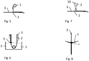
- FIG 6 again shows a schematic side view of a heated basin 8 in which molten lithium is contained.
- the electrode 2 with the layer 3 applied thereon is passed through the basin 8.
- a scraper 9 When leaving the basin 8, it is possible to wipe off excess lithium on a scraper 9 and thereby set a layer thickness of the lithium layer on the surface of the electrode 2 that is identical on both sides.
- FIG. 7 An exemplary embodiment is shown in which the coating of the electrode surface provided with the layer 3 is carried out by means of a spray coating, in which the lithium is deposited from a spray nozzle 10 onto the substrate passing below the spray nozzle 10.
- the electrode 2 is coated on both sides by feeding lithium as a solid to the electrode 2 from both sides. Since the electrode 2 is heated by a Pass-through nozzle 11 is passed before the lithium hits the layer 3 arranged on both sides of the electrode 2 on the electrode surface, melts there and the electrode 2 is coated in such a way that a closed lithium layer is formed.
- a large-area deposition of lithium on different substrates 2 can thus be made possible by applying a thin, typically between 0.1 nm and 1000 nm thick lithiophilic layer 3.
- lithiophilic layer 3 typically between 0.1 nm and 1000 nm thick lithiophilic layer 3.
- carbon / graphite, silicon, NiMnCo oxide or MnO2-containing materials can be used as electrode materials.
- the layer 3 can be formed from an oxide of silicon, tin, zinc, antimony, aluminum, magnesium, bismuth.
- an oxidic mediator layer 3 can be used, which is at least partially (but also completely) reduced by lithium.
- This oxidic mediator layer can therefore have a metal oxide, with oxides or oxide compounds of the following elements being possible as the metal oxide: magnesium, aluminum, silicon, calcium, titanium, vanadium, chromium, manganese, iron, cobalt, nickel, copper, zinc, zirconium, Molybdenum, indium, tin, antimony, lead, bismuth.
- These materials can also be used without oxidation, since they form alloys with lithium, which also have a lithiophilic effect.
- materials can be used in which the lithium intercalates, for example carbons such as graphite or hard carbons.
- a 12 ⁇ m thick copper foil can be superficially oxidized in a preheated muffle furnace (or in a high-temperature tunnel furnace for continuous substrates) at 300 ° C to 500 ° C to form a thin oxide layer with a thickness between 0.1 nm and 1000 nm, which serves as the layer 3.
- a nickel oxide layer can be formed at 600 ° C. by oxidation of a 20 ⁇ m thick nickel foil.
- the formation of Cu 2 O can be detected by means of X-ray diffraction (XRD).
- a graphite electrode as electrode material can be coated in an ethanolic SnCl 2 solution or SbCl 3 solution (0.15 M) for 30 s, dried for 5 minutes and then tempered in air in a preheated muffle furnace at 300 ° C. for 5 minutes will. The electrode 2 produced in this way is then immersed in a lithium melt.
- a graphite electrode can also be coated in an isopropanolic zinc acetate solution for 30 s, dried for 5 minutes and then tempered in air in a preheated muffle furnace at 400 ° C. for 60 min. The electrode 2 produced in this way is then immersed in a lithium melt.
- an NMC electrode can also be soaked in an isopropanolic suspension of zinc oxide nanoparticles for 30 s, dried for 5 minutes and then tempered in air in a preheated muffle furnace at 80 ° C. for 10 min. The electrode 2 produced in this way is then immersed in a lithium melt.
- a Si electrode can also be brought into contact with a copper foil as a temporary substrate, which contains the thin lithium layer, under pressure and temperature, in order to make the lithium flow. After the lithium has been transferred from the temporary substrate to the Si electrode 2, the temporary substrate is removed. The electrode 2 produced in this way is then immersed in a lithium melt.
- the powdery electrode starting material can also be provided with a lithiophilic surface.
- the material is then processed into an electrode 2 as standard and coated with liquid lithium as described here.
- Electrodes for secondary batteries such as lithium-ion batteries, lithium-air batteries, lithium-sulfur batteries or solid-state batteries or electrodes 2 for primary batteries such as lithium-thionyl chloride batteries, lithium-manganese oxide batteries, lithium-sulfur oxide batteries, lithium -Carbon monofluoride batteries, lithium iodine batteries or lithium iron sulfide batteries are manufactured.
- separators or temporary substrates can also be treated in this way.
Landscapes
- Chemical & Material Sciences (AREA)
- Engineering & Computer Science (AREA)
- Chemical Kinetics & Catalysis (AREA)
- Materials Engineering (AREA)
- Mechanical Engineering (AREA)
- Metallurgy (AREA)
- Organic Chemistry (AREA)
- Electrochemistry (AREA)
- General Chemical & Material Sciences (AREA)
- Physics & Mathematics (AREA)
- Manufacturing & Machinery (AREA)
- Plasma & Fusion (AREA)
- Oil, Petroleum & Natural Gas (AREA)
- Thermal Sciences (AREA)
- Battery Electrode And Active Subsutance (AREA)
Abstract
Description
- Die Erfindung betrifft ein Verfahren zur Lithiierung von Elektroden von lithiumbasierten elektrischen Energiespeicherelementen sowie mit dem Verfahren hergestelltes elektrisches Energiespeicherelement.
- Aktuelle und zukünftige lithiumbasierte Elektroenergiespeicherelemente, wie z.B. Batterien sollen gesteigerte spezifische Energiedichten bei hoher Zyklenstabilität aufweisen. Für die Realisierung zyklenstabiler Zellen ist es notwendig, irreversible Lithiumverluste während der Lade- und Entladezyklen zu vermeiden bzw. auszugleichen. Je nach Zelltyp und Zellchemie können irreversible Lithiumverluste u.a. durch Bildung einer festen Grenzschicht zum Elektrolyten (solid electrolyte interface → SEI) oder beispielsweise durch parasitäre Nebenreaktionen auftreten. In diesen Fällen ist es erforderlich, zusätzliches Lithium in die Zelle einzubringen bzw. vorzuhalten, was durch Schaffung eines Lithium-Reservoirs erreicht werden kann. Dies ist z.B. bei Lithium-Ionen-Batterien der Fall.
- Zudem gibt es lithiumbasierte Energiespeicher, bei denen die Elektrodenaktivmaterialien selbst kein Lithium beinhalten und sämtliches Lithium durch Additive oder Zusatzkomponenten in die Zelle eingebracht werden muss. Beispiele hierfür sind Lithium-Ionen-Kondensatoren oder Silizium-Lithium-Schwefel-Batterien. In diesen Fällen ist eine sogenannte Prälithiierung erforderlich.
- Alternativ kann Lithium in Form von Lithiumpulver auf Anoden für Li-Ionen-Zellen aufgebracht werden. Die Auftragung erfolgt in Pastenform und führt zu relativ rauen und porösen Strukturen mit großer Oberfläche, die zu gesteigerter SEI-Bildung führen.
- Zusätzliches Lithium kann auch durch physikalische Gasphasenabscheidung (PVD) aufgetragen werden. Bei diesem Prozess wird Lithium verdampft und als dünne Schicht auf einem Substrat, z.B. Elektrode, abgeschieden. Dabei ist aber die große erforderliche Zeitdauer wegen der geringen Abscheiderate nachteilig.
- Andere Elektroden (z.B. Graphit oder Silizium-Anoden) können elektrochemisch prälithiiert werden. Dort muss die Elektrode in einer elektrochemischen Zelle gegen eine Lithium-spendende Opferelektrode (bspw. metallisches Lithium) verbaut werden. Auf diese Weise wird der Opferelektrode das Lithium entzogen und in die Zielelektrode eingelagert. Anschließend wird die Prälithiierungs-Zelle deassembliert und die lithiierte Elektrode in die Zielzelle verbaut.
- Es ist daher Aufgabe der Erfindung, Möglichkeiten für einen einfachen und kostengünstigen sowie dauerhaften Erhalt der Elektroenergiespeicherkapazität von lithiumbasierten Elektroenergiespeicherelementen anzugeben.
- Erfindungsgemäß wird diese Aufgabe mit einem Verfahren, das die Merkmale des Anspruchs 1 aufweist, gelöst. Anspruch 11 und 12 betrifft ein mit dem Verfahren lithiiertes Elektroenergiespeicherelement. Vorteilhafte Weiterbildungen und Ausführungsmöglichkeiten sind mit in untergeordneten Ansprüchen bezeichneten Merkmalen realisierbar.
- Bei dem Verfahren wird Lithium mit einer Menge in eine jeweilige Elektrode eingebracht, mit der irreversible Lithiumverluste, die während Entlade- und Ladevorgängen auftreten, vollständig ausgeglichen werden oder im Falle von unlithiierten Materialien, die gesamte benötigte Lithium-Menge bereit gestellt wird. Dabei wird das geschmolzenes Lithium in flüssiger Phase während des Auftrags auf eine Oberfläche oder des Einbringens in einen jeweiligen Elektrodenwerkstoff eingesetzt. Für ein vollständiges Ausgleichen der Verluste werden 1 % - 20 % der Elektrodenkapazität oder für die gesamte für eine Lithiierung der Elektrode benötigte Lithiummenge werden 100 % - 120 % der Elektrodenkapazität eingesetzt.
- Zwischen dem Lithium und der Oberfläche von Elektrodenwerkstoff und/oder einer Oberfläche eines temporären Substrats, auf der eine Lithiumschicht aufgebracht wird, kann vorteilhaft eine Schicht, die mit einem lithiophilen Material gebildet ist, das mit dem flüssigen Lithium durch zumindest teilweise chemische Reduktion reagiert, interkaliert oder legiert, ausgebildet werden. Im Speziellen ist dies ein Metalloxid. Bei der chemischen Reaktion sollte zumindest teilweise eine chemische Reduktion des Metalloxids erreicht werden.
- Das flüssige Lithium sollte anschließend durch Erstarren in die feste Phase überführt werden oder die Elektrode kann durch weitere Prozessschritte direkt lithiiert werden.
- Als lithiiophile Materialien können Metalloxide, insbesondere Zinkoxid, Kupferoxid, Nickeloxid, Zinnoxid, Interkalationsmaterialien, insbesondere Kohlenstoffe, oder Legierungsbildner, insbesondere Silizium, eingesetzt werden.
- Lithium sollte in einer Menge, die 1 % bis 120 % der Kapazität der Elektrode des jeweiligen elektrische Energiespeicherelements entspricht, auf-oder eingebracht werden. Dabei wird die jeweilig erforderliche Menge von der Art des Elektrodenwerkstoffs und des jeweiligen elektrische Energiespeicherelements beeinflusst. So ist es beispielsweise in typischen Li-Ionen-Zellen notwendig 1 %- 20% Kapazität zuzuführen, während Li-Ionen-Kondensatoren, Lithium-Schwefel-Zellen und ähnliche Systeme 100 % - 120 % Kapazität zugeführt bekommen müssen.
- So kann gemäß einer erfindungsgemäßen Alternative eine Oberfläche des Elektrodenwerkstoffs, eines Separators und/oder eines temporären Substrats mit dem jeweiligen lithiophilen Material beschichtet und anschließend flüssiges Lithium mit über die jeweilige Oberfläche konstanter Schichtdicke aufgebracht werden. Die Lithiumschicht kann dabei durch Laserschmelzen, Schmelzen mittels einer Heizvorrichtung, Rakeln, Aufbringen mittels einer Schlitzdüse, Streichen, Sprühen von Alkalimetallschmelzen, Tauchbeschichten, Gasphasenverfahren, thermisches Spritzen und bzw. oder Laminieren aufgebracht werden. Dabei sollte eine konstante Schichtdicke, mit der die jeweilige Menge an Lithium bestimmt ist, über die jeweilige beschichtete Oberfläche eingehalten werden.
- Bei einer Beschichtung einer Oberfläche eines temporären Substrats wird nach dem Aufbringen der Lithiumschicht, diese Oberfläche mit der Oberfläche der jeweiligen Elektrode oder eines Separators in berührenden Kontakt gebracht und infolge erhöhter Temperatur, wirkendem Druck und/oder die Wirkung eines elektrischen Feldes wird diese Lithiumschicht nach eventueller erneuter Verflüssigung, Erweichen, fließfähig machen, von der Oberfläche des temporären Substrats auf eine Oberfläche derjeweiligen Elektrode oder eines Separators übertragen.
- Es besteht auch die Möglichkeit, lithiophile Partikel in den Elektrodenwerkstoff einzubringen und dann die jeweilige Oberfläche der Elektrode mit flüssigem Lithium zu beaufschlagen, wie dies bereits erläutert worden ist.
- Bei einer weiteren erfindungsgemäßen Alternative können Lithiumpartikel gemeinsam mit dem jeweiligen Metalloxid in den jeweiligen Elektrodenwerkstoff eingebracht und dann das Lithium verflüssigt werden, dabei reagiert es mit dem Metalloxid chemisch und ist nach dem Erstarren im Elektrodenwerkstoff enthalten. Das Einbringen der beschichteten Lithiumpartikel kann bei der Herstellung des Elektrodenwerkstoffs vor oder bei seiner Applikation auf einen Separator oder Elektrolyten durchgeführt werden. Die beschichteten Lithiumpartikel sollten im Elektrodenwerkstoff homogen verteilt sein. Die jeweilige Lithiummenge kann man über die Partikelgröße und Partikelanzahl bei
- Beachtung der jeweiligen physikalischen Dichte des Lithiums berücksichtigen.
- Eine mit dem lithiophilen Material gebildete Schicht kann mit einer Dicke zwischen 0,1 nm und 1000 nm, vorzugsweise zwischen 1 nm und 500 nm, besonders vorzugsweise zwischen 10 nm und 200 nm ausgebildet werden.
- Diese Schicht kann einfach durch Oxidation des Werkstoffs aus dem ein jeweilige Elektrode, ein Separator und/oder ein temporäres Substrat an der jeweiligen Oberfläche ausgebildet werden.
- Es besteht aber auch die Möglichkeit, die mit Metalloxid gebildete Schicht mit einer Suspension, in der Partikel des Metalloxids enthalten sind, als Beschichtung auf die jeweilige Oberfläche oder die Oberfläche von Lithiumpartikeln aufzubringen. Nach dem Suspensionsauftrag kann der Flüssigkeits- und ggf. ein Binderanteil der Suspension, bevorzugt durch Verdampfen entfernt werden. Bei diesem Vorgehen können größere Dicken der Metalloxidschicht auftreten.
- Als Elektrodenwerkstoff kann man Kohlenstoff/Graphit-, Silicium-, NiMnCo-Oxid- oder MnO2-haltige Materialien einsetzen.
- Es können Lithiumreservoirs erhalten oder es kann eine Prälithiierung unter Verwendung dünner (Schichtdicke 0,5 µm - 50 µm) Lithiumschichten durchgeführt werden. In einer erfindungsgemäßen Alternative kann analog zu dem Schmelzbeschichtungsverfahrens, wie es in
DE 10 2017 208 218 A1 beschrieben ist, vorgegangen werden. Die Besonderheit des Lösungsweges besteht darin, dass die benötigte Lithiummenge bzw. der Lithiumüberschuss exakt über die abgeschiedene Lithium-Schichtdicke eingestellt werden kann, was somit eine exakte Abstimmung auf die Kapazität der verwendeten Elektrode erlaubt. - Die jeweilige Elektrode kann an einer Oberfläche direkt mit Lithium beschichtet werden. Dazu wird eine lithiophile Schicht auf eine Oberfläche einer jeweiligen Elektrode, eines Separators und/oder eines temporären Substrats aufgetragen oder dort ausgebildet. Diese Schicht ist im Wesentlichen mit lithiophilem Material gebildet. Anschließend kann eine exakt auf die Kapazität der jeweiligen Elektrode abgestimmte Lithiumschichtdicke mittels Schmelzverfahren appliziert werden. Dabei sollte durch die applizierte Lithium-Dünnschicht, je nach Anwendungsfall, ein Bereich von 1 % -120 % der Elektrodenkapazität eingehalten werden können.
- Alternativ kann das Lithium auf einer von der zu lithiierenden Elektrode verschiedenen Substratoberfläche eines temporären Substrats aufgebracht werden, um dann durch ein Transferverfahren (Zeit, Temperatur, Druck, elektrisches Feld) gezielt eine Elektrode zu lithiieren. Das von der zu lithiierenden Elektrode verschiedene Substrat wird dabei nur temporär genutzt. Somit ist es möglich, Zellkomponenten (z.B. Separator) mit einer Lithiummetallbeschichtung auszurüsten und in einer Zelle eines Elektroenergiespeicherelements zu verbauen, oder das Lithium in einem dem Zellbau vorgelagerten Prozessschritt über ein temporäres Substrat in die jeweilige Elektrode zu transferieren. Für ein temporäres Substrat kann man Kupfer, Nickel, Edelstahl, Polymerfolien oder ähnliches als Werkstoff einsetzen. Die jeweilige zu beschichtende Oberfläche eines temporären Substrats sollte eben und planar oder komplementär zur Oberfläche, auf die die Lithiumschicht transferiert werden soll, ausgebildet sein.
- Der Vorteil der Erfindung liegt in der Möglichkeit die Menge des abgeschiedenen Lithiums sehr genau einzustellen, was über die Menge an Lithium, insbesondere über die Schichtdicke einer Lithiumbeschichtung erreicht werden kann und damit genau den Lithiumverlust auszugleichen bzw. den Grad der Lithiierung (1 %-120 %) exakt auf die Kapazität der jeweiligen Elektrode anzupassen.
- Mit der Erfindung wird kein unnötiges Lithium in das jeweilige Elektroenergiespeicherelement verbaut und seine Dicke kann minimiert werden.
- Es können folgende Vorteile im Vergleich zu konkurrierenden Ansätzen erreicht werden:
- im Vergleich zu dicken Lithiumfolien: Beim erfindungsgemäßen Vorgehen kann die exakte benötigte Menge an Lithium eingebracht werden. Mit dicken Li-Folien ist dies häufig überhaupt nicht möglich. Im Vergleich zur Verwendung von Lithiumpartikeln innerhalb der Schicht: diese Partikel werden verbraucht - zurück bleiben unerwünschte Hohlräume. Beim erfindungsgemäßen Verfahren entstehen derartige Hohlräume nicht.
- Vorteil im Vergleich zur Elektrochemischen Prälithiierung: Der Aufwand wird beim erfindungsgemäßen Vorgehen deutlich reduziert.
- Vorteil im Vergleich zur PVD: Es werden ähnliche Schichten erzeugt. Die Herstellung der Schichten ist beim erfindungsgemäßen Verfahren jedoch deutlich effizienter.
- Es kann eine Lithiierung von Elektroden für lithiumbasierte Energiespeicher, z.B. folgende Sekundärbatterien
- ∘ Lithium-Ionen-Batterien (u.a.Graphit-Anoden, Si-basierte Anoden, unlithiierte Kathoden (z.B. Mn02))
- ∘ Lithium-Schwefel-Batterien (Si oder Kohlenstoffanoden)
- ∘ Festkörperbatterien (Si oder Kohlenstoffanoden)
- ∘ Li-Luft-Batterien (Si oder Kohlenstoffanoden)
- Nachfolgend soll die Erfindung beispielhaft näher erläutert werden.
- Dabei zeigen:
- Fig. 1
- eine schematische seitliche Ansicht eines Lithiumauftrags mittels einer beheizten Düse;
- Fig. 2
- eine
Figur 1 entsprechende Ansicht des Lithiumauftrags mittels eines beheizten Reservoirs; - Fig. 3
- eine
Figur 1 entsprechende Ansicht des Lithiumauftrags mittels Laserschmelzen; - Fig. 4
- eine
Figur 1 entsprechende Ansicht des Lithiumauftrags mittels Rakeln; - Fig. 5
- eine
Figur 1 entsprechende Ansicht des Lithiumauftrags mittels Streichen; - Fig. 6
- eine
Figur 1 entsprechende Ansicht des Lithiumauftrags mittels einer Tauchbeschichtung; - Fig. 7
- eine
Figur 1 entsprechende Ansicht des Lithiumauftrags mittels einer Sprühbeschichtung und - Fig. 8
- eine
Figur 1 entsprechende Ansicht des Lithiumauftrags mittels Durchlaufdüse. -
Figur 1 zeigt in einer schematischen seitlichen Ansicht ein Verfahren zum Lithiieren einer Oberfläche einer Elektrode 2. Die Elektrode 2 ist im dargestellten Ausführungsbeispiel eine Graphitelektrode, die durch Dipcoating mit einer Zinkoxid-Schicht als Schicht 3 versehen wurde. Somit ist die Schicht 3 in direktem, also unmittelbar berührenden Kontakt mit der Elektrodenoberfläche. Ein Aufschmelzen des Lithiums wird durch eine beheizte Düse 5 bewirkt. Die Lithiumfolie wird durch die elektrisch beheizte Düse 5 geführt und hierbei aufgeschmolzen. Fluchtend unterhalb der Düse 5 wird die Elektrode 2 vorbeigeführt, auf dem wiederum die Schicht 3 angeordnet ist. Das geschmolzene Lithium trifft nun auf eine der Düse 5 zugewandte Oberfläche der Schicht 3, erkaltet dort und geht wieder in einen festen Aggregatzustand über, so dass sich eine geschlossene, porenfreie Lithiumschicht ausbildet, die in direktem Kontakt mit der Schicht 3 steht. - Wie in
Figur 2 in einerFigur 1 entsprechenden Ansicht gezeigt, kann auch ein, vorzugsweise elektrisch, beheiztes Reservoir 6 verflüssigtes Lithium aufnehmen und durch eine der Oberfläche der Elektrode 2 zugewandte Schlitzdüse des Reservoirs 6 das Lithium auf die Schicht 3 auftragen. Das Reservoir 6 ist hierbei trichterförmig, um ein gezieltes Ausfließen durch die Schlitzdüse zu ermöglichen. Wiederkehrende Merkmale sind in dieser Figur und den folgenden Figuren mit identischen Bezugszeichen versehen. - In einer weiteren Ausführungsform der Erfindung, die in
Figur 3 dargestellt ist, wird durch eine Laserstrahlungsquelle 4 elektromagnetische Laserstrahlung auf einen Auftreffpunkt des folienförmigen Lithiums auf die Elektrodenoberfläche 2 bzw. die Schicht 3 gerichtet, so dass das folienförmige Lithium an dieser Stelle verflüssigt wird und durch die Schicht 3 aus Zinkoxid auf der Oberfläche der Elektrode 2 angeordnet wird. - In einer weiteren Ausführungsform, die in
Figur 4 wiedergegeben ist, wird die Elektrode 2 beheizt und Lithium 1 liegt als Schmelze auf der Oberfläche der Elektrode 2 auf. Mittels einer Rakel 7 wird das Lithium mit einer definierten Dicke abgestreift und auf die Schicht 3, die wie zuvor einer Quelle des aufzubringenden Lithiums 1 zugewandt ist, aufgebracht. - In dem in
Figur 5 dargestellten Ausführungsbeispiel wird kalte Lithiumfolie über eine heiß erwärmte Elektrode 2 geführt. Die Elektrode 2 wird hierbei durch einen elektrischen Ofen geführt und dabei erwärmt. Durch Streichen der kalten Lithiumfolie über die Oberfläche der Elektrode 2 schmilzt die Lithiumfolie am Auftreffpunkt auf der auf der Elektrodenoberfläche vorhandenen Schicht 3 auf und benetzt diese Schicht 3 flächig. Nach Erkalten liegt somit wiederum eine geschlossene Lithiumbeschichtung vor. -
Figur 6 zeigt wiederum in einer schematischen seitlichen Ansicht ein beheiztes Becken 8, in dem geschmolzenes Lithium enthalten ist. Die Elektrode 2 mit darauf aufgebrachter Schicht 3 wird durch das Becken 8 geführt. Beim Verlassen des Beckens 8 ist es möglich, überschüssiges Lithium an einem Abstreifer 9 abzustreifen und dadurch eine beidseitig identische Schichtdicke der Lithiumschicht auf der Oberfläche der Elektrode 2 einzustellen. - In
Figur 7 ist ein Ausführungsbeispiel gezeigt, bei die Beschichtung der mit der Schicht 3 versehenen Elektrodenoberfläche mittels einer Sprühbeschichtung erfolgt, bei der aus einer Sprühdüse 10 auf das unterhalb der Sprühdüse 10 vorbeilaufende Substrat das Lithium abgeschieden wird. - Bei dem in
Figur 8 wiedergegebenen Ausführungsbeispiel erfolgt eine beidseitige Beschichtung der Elektrode 2, indem von beiden Seiten Lithium als Festkörper zu der Elektrode 2 geführt wird. Da die Elektrode 2 durch eine beheizte Durchlaufdüse 11 geführt wird, bevor das Lithium auf die Elektrodenoberfläche die auf beiden Seiten der Elektrode 2 angeordnete Schicht 3 auftrifft, dort aufschmilzt und die Elektrode 2 derart beschichtet, dass eine geschlossene Lithiumschicht ausgebildet wird. - Mit dem in verschiedenen Ausführungsformen beschriebenen Verfahren kann somit durch Aufbringen einer dünnen, typischerweise zwischen 0,1 nm und 1000 nm dicken lithiophilen Schicht 3 eine großflächige Abscheidung von Lithium auf unterschiedlichen Substraten 2 ermöglicht werden. Als Elektrodenwerkstoffe können beispielsweise Kohlenstoff/Graphit-, Silicium-, NiMnCo-Oxid- oder MnO2-haltige Materialien verwendet werden.
- Die Schicht 3 kann aus einem Oxid von Silizium, Zinn, Zink, Antimon, Aluminium, Magnesium, Bismut gebildet sein.
Generell kann eine oxidische Vermittlerschicht 3 verwendet werden, die durch Lithium zumindest teilweise (aber auch vollständig) reduziert wird. Diese oxidische Vermittlerschicht kann also ein Metalloxid aufweisen, wobei als das Metalloxid Oxide oder Oxidverbindungen folgender Elemente in Frage kommen: Magnesium, Aluminium, Silizium, Calcium, Titan, Vanadium, Chrom, Mangan, Eisen, Cobalt, Nickel, Kupfer, Zink, Zirkonium, Molybdän, Indium, Zinn, Antimon, Blei, Bismut. Diese Materialien können auch ohne Oxidation eingesetzt werden, da sie mit Lithium Legierungen bilden, welche ebenfalls eine lithiophile Wirkung aufweisen. Desweiteren können Materialien eingesetzt werden, in welche das Lithium interkaliert, z.B. Kohlenstoffe wie Graphit oder Hard Carbons. - Zum Ausbilden der Schicht 3 auf einer Oberfläche eines temporären Substrats können, wie zum Aufbringen des Lithiums 1 verschiedene Prozeduren angewandt werden. So kann beispielsweise eine 12 µm dicke Kupferfolie in einem vorgeheizten Muffelofen (oder in einem Hochtemperaturdurchlaufofen für kontinuierliche Substrate) bei 300 °C bis 500 °C oberflächlich oxidiert werden, um eine dünne Oxidschicht mit einer Dicke zwischen 0,1 nm und 1000 nm, die als die Schicht 3 dient, zu erhalten. In gleicher Weise kann auch durch Oxidation einer 20 µm dicken Nickelfolie eine Nickeloxidschicht bei 600 °C ausgebildet werden. Mittels Röntgenbeugung (XRD, X-ray diffraction) kann die Bildung von Cu2O nachgewiesen werden. In einer Ar-Umgebung kann anschließend festes Lithium in Kontakt mit der oxidierten und auf 200 °C aufgeheizten Kupferfolie gebracht werden, was zum Aufschmelzen des Lithiums führt. Mittels der Rakel 7 kann dann, wie in
Figur 4 gezeigt, eine 1 µm bis 50 µm dicke Lithiumschicht 1 generiert werden. - In einem weiteren Ausführungsbeispiel kann eine Graphitelektrode als Elektrodenwerkstoff für 30 s in einer ethanolischen SnCl2-Lösung oder SbCl3-Lösung (0,15 M) beschichtet, 5 Minuten getrocknet und anschließend an Luft im vorgeheizten Muffelofen bei 300 °C für 5 Minuten getempert werden. Die auf diese Weise hergestellte Elektrode 2 wird anschließend in eine Lithiumschmelze getaucht.
- In einem weiteren Ausführungsbeispiel kann auch eine Graphit-Elektrode für 30 s in eine isopropanolische Zinkacetat-Lösung beschichtet werden, 5 Minuten getrocknet und anschließend an Luft im vorgeheizten Muffelofen bei 400°C für 60 min getempert werden. Die auf diese Weise hergestellte Elektrode 2 wird anschließend in eine Lithiumschmelze getaucht.
- In einem weiteren Ausführungsbeispiel kann auch eine NMC-Elektrode für 30 s in eine isopropanolische Suspension von Zinkoxid-Nanopartikeln getränkt werden, 5 Minuten getrocknet und anschließend an Luft im vorgeheizten Muffelofen bei 80°C für 10 min getempert werden. Die auf diese Weise hergestellte Elektrode 2 wird anschließend in eine Lithiumschmelze getaucht.
- In einem weiteren Ausführungsbeispiel kann auch eine Si-Elektrode mit einer Kupferfolie als temporäres Substrat, das die dünne Lithiumschicht enthält unter Druck und Temperatur in Kontakt gebracht werden, um das Lithium zum Fließen zu bringen. Nach dem Übertrag des Lithiums vom temporären Substrat auf die Si-Elektrode 2 wird das temporäre Substrat entfernt. Die auf diese Weise hergestellte Elektrode 2 wird anschließend in eine Lithiumschmelze getaucht.
- In einem weiteren Ausführungsbeispiel kann auch das pulverförmige Elektroden-Ausgangsmaterial mit einer lithiophilen Oberfläche versehen werden. Anschließend wird das Material standardmäßig zu einer Elektrode 2 verarbeitet und wie hier beschrieben, mit flüssigem Lithium beschichtet.
- Während sich beispielsweise Lithiumkugeln auf einer unbehandelten Oberfläche einer Kupferfolie nicht zum Benetzen eignen, kann bei einem Erwärmen in Argon auf ungefähr 200 °C bei einer wie beschrieben behandelten Oberfläche die Lithiumkugel die Folienoberfläche benetzen. Somit können Elektroden für Sekundärbatterien wie Lithium-Ionen-Batterien, Lithium-Luft-Batterien, Lithium-Schwefel-Batterien oder Festkörperbatterien oder Elektroden 2 für Primärbatterien wie Lithium-Thionylchlorid-Batterien, Lithium-Manganoxid-Batterien, Lithium-Schwefeloxid-Batterien, Lithium-Kohlenstoffmonofluorid-Batterien, Lithium-Iod-Batterien oder Lithium-Eisensulfid-Batterien hergestellt werden.
- Anstelle von Elektroden 2 kann man analog auch Separatoren oder temporäre Substrate so behandeln.
- Lediglich in den Ausführungsbeispielen offenbarte Merkmale der verschiedenen Ausführungsformen können miteinander kombiniert und einzeln beansprucht werden.
∘ Li-Ionen-Kondensatoren erreicht werden.
Claims (13)
- Verfahren zur Beschichtung von Elektroden von lithiumbasierten elektrischen Energiespeicherelementen, bei dem Lithium (1) mit einer Menge in eine jeweilige Elektrode (2) eingebracht wird, mit der irreversible Lithiumverluste, die während Entlade- und Ladevorgängen auftreten, vollständig ausgeglichen werden mit 1 % - 20 % der Elektrodenkapazität oder die gesamte für eine Lithiierung der Elektrode benötigte Lithiummenge mit 100 % - 120 % der Elektrodenkapazität zur Verfügung gestellt wird und dabei
das geschmolzene metallische Lithium in flüssiger Phase während des Auftrags auf eine Oberfläche oder des Einbringens in einen jeweiligen Elektrodenwerkstoff eingesetzt wird. - Verfahren nach Anspruch 1, dadurch gekennzeichnet, dass vor dem Einbringen des Lithiums (1) zwischen dem Lithium (1) und der Oberfläche von Elektrodenwerkstoff und/oder einer Oberfläche eines temporären Substrats, auf der eine Lithiumschicht aufgebracht wird, eine Schicht (3), die mit einem lithiophilen Material gebildet ist, aufgebracht oder ausgebildet wird.
- Verfahren nach einem der vorhergehenden Ansprüche, dadurch gekennzeichnet, dass das flüssige Lithium (1) anschließend durch Erstarren in die feste Phase überführt wird oder direkt beim Auftrag in den Elektrodenwerkstoff lithiiert.
- Verfahren nach einem der vorhergehenden Ansprüche, dadurch gekennzeichnet, dass als lithiiophiles Material Metalloxide, insbesondere Zinkoxid, Kupferoxid, Nickeloxid, Zinnoxid, Siliziumoxid, Aluminiumoxid aber auch oxidierte Kohlenstoffe, Interkalationsmaterialien, insbesondere Kohlenstoffe, oder Legierungsbildner, insbesondere Silizium, Antimon, Zinn, Gold eingesetzt wird.
- Verfahren nach einem der vorhergehenden Ansprüche, dadurch gekennzeichnet, dass Lithium (1) in einer Menge, die 1 % bis 120 % der Kapazität der Elektrode (2) des jeweiligen elektrischen Energiespeicherelements entspricht auf - oder eingebracht wird.
- Verfahren nach einem der vorhergehenden Ansprüche, dadurch gekennzeichnet, dass eine Oberfläche des Elektrodenwerkstoffs und/oder eines temporären Substrats mit dem jeweiligen lithiophilen Material beschichtet und anschließend flüssiges Lithium (1) mit über die jeweilige Oberfläche konstanter Schichtdicke aufgebracht wird und bei einer Beschichtung einer Oberfläche eines temporären Substrats nach dem Aufbringen der Lithiumschicht, diese Oberfläche mit der Oberfläche der jeweiligen Elektrode in berührenden Kontakt gebracht und infolge erhöhter Temperatur, wirkendem Druck und/oder die Wirkung eines elektrischen Feldes die Lithiumschicht nach erneuter Verflüssigung diese Lithiumschicht von der Oberfläche des temporären Substrats auf eine Oberfläche der Elektrode (2) übertragen wird.
- Verfahren nach einem der vorhergehenden Ansprüche, dadurch gekennzeichnet, dass Partikel des lithiophilen Materials in den jeweiligen Elektrodenwerkstoff eingebracht werden und dann das geschmolzene Lithium (1) flüssig aufgebracht wird.
- Verfahren nach einem der vorhergehenden Ansprüche, dadurch gekennzeichnet, dass Lithium (1) durch Laserschmelzen, Schmelzen mittels einer Heizvorrichtung, Rakeln, Aufbringen mittels einer Schlitzdüse, Sprühen, Streichen, Tauchbeschichten, thermisches Spritzen und/oder Laminieren auf die mit dem jeweiligen lithiophilen Material gebildete Schicht (3) aufgebracht wird.
- Verfahren nach einem der vorhergehenden Ansprüche, dadurch gekennzeichnet, dass die mit dem lithiophilen Material gebildete Schicht (3) mit einer Dicke zwischen 0,1 nm und 1000 nm, vorzugsweise zwischen 1 nm und 500 nm, besonders vorzugsweise zwischen 10 nm und 200 nm ausgebildet wird.
- Verfahren nach einem der vorhergehenden Ansprüche, dadurch gekennzeichnet, dass die Schicht (3), die mit Metalloxid gebildet ist, durch Oxidation des Werkstoffs aus dem die jeweilige Elektrode (2)und/oder ein temporäres Substrat an der jeweiligen Oberfläche ausgebildet oder
in Form einer Suspension, in der Partikel des Metalloxids enthalten sind, als Beschichtung auf die jeweilige Oberfläche oder die Oberfläche von Lithiumpartikeln aufgebracht wird. - Elektrisches Energiespeicherelement, bei dem eine Elektrode mit einem Verfahren nach einem der vorhergehenden Ansprüche so lithiiert worden ist, dass Lithium (1) mit einer Menge 1 % - 20 % in der jeweiligen Elektrode (2) enthalten ist, mit der irreversible Lithiumverluste, die während Entlade- und Ladevorgängen auftreten, vollständig ausgeglichen werden.
- Elektrisches Energiespeicherelement, bei dem eine Elektrode mit einem Verfahren nach einem der Ansprüche 1 bis 10 so lithiiert worden ist, dass Lithium (1) mit einer Menge 100 % - 120 % in der jeweiligen Elektrode (2) enthalten ist, die den gesamten Lithiumbedarf in einer jeweiligen Zelle eines elektrischen Energiespeicherelements darstellt.
- Elektrisches Energiespeicherelement nach einem der zwei vorhergehenden Ansprüche, dadurch gekennzeichnet, dass es eine Lithium-Ionen-Batterie, eine Lithium-Schwefel-Batterie, eine Festkörperbatterie, eine Li-Luft-Batterie oder ein lithiumbasierter Kondensator ist.
Applications Claiming Priority (1)
| Application Number | Priority Date | Filing Date | Title |
|---|---|---|---|
| DE102019209397.3A DE102019209397A1 (de) | 2019-06-27 | 2019-06-27 | Verfahren zur Lithiierung von Elektroden von lithiumbasierten elektrischen Energiespeicherelementen sowie mit dem Verfahren hergestelltes elektrisches Energiespeicherelement |
Publications (2)
| Publication Number | Publication Date |
|---|---|
| EP3758105A1 true EP3758105A1 (de) | 2020-12-30 |
| EP3758105B1 EP3758105B1 (de) | 2023-10-18 |
Family
ID=71103291
Family Applications (1)
| Application Number | Title | Priority Date | Filing Date |
|---|---|---|---|
| EP20180244.4A Active EP3758105B1 (de) | 2019-06-27 | 2020-06-16 | Verfahren zur lithiierung von elektroden von lithiumbasierten elektrischen energiespeicherelementen sowie mit dem verfahren hergestelltes elektrisches energiespeicherelement |
Country Status (2)
| Country | Link |
|---|---|
| EP (1) | EP3758105B1 (de) |
| DE (1) | DE102019209397A1 (de) |
Cited By (4)
| Publication number | Priority date | Publication date | Assignee | Title |
|---|---|---|---|---|
| CN113964374A (zh) * | 2021-10-19 | 2022-01-21 | 远景动力技术(江苏)有限公司 | 极片的预锂化装置及其预锂化方法 |
| WO2023184042A1 (en) * | 2022-04-01 | 2023-10-05 | Nanoxplore Inc. | Lithium-coated anode particles and methods of producing the same |
| CN116960263A (zh) * | 2022-04-20 | 2023-10-27 | 通用汽车环球科技运作有限责任公司 | 制作用于电化学单池的电极的方法 |
| US12291455B2 (en) | 2023-04-11 | 2025-05-06 | Nanoxplore Inc. | Anode particles including discarded graphite particles, and methods of producing the same |
Families Citing this family (1)
| Publication number | Priority date | Publication date | Assignee | Title |
|---|---|---|---|---|
| US20250087660A1 (en) * | 2023-09-07 | 2025-03-13 | GM Global Technology Operations LLC | Surface modification of current collector prior to coating with molten metal |
Citations (3)
| Publication number | Priority date | Publication date | Assignee | Title |
|---|---|---|---|---|
| US20170133662A1 (en) * | 2015-11-11 | 2017-05-11 | The Board Of Trustees Of The Leland Stanford Junior University | Composite lithium metal anodes for lithium batteries with reduced volumetric fluctuation during cycling and dendrite suppression |
| WO2017120391A1 (en) * | 2016-01-08 | 2017-07-13 | The Texas A&M University System | Large energy density batteries and methods of manufacture |
| DE102017208218A1 (de) | 2017-05-16 | 2018-11-22 | Fraunhofer-Gesellschaft zur Förderung der angewandten Forschung e.V. | Verfahren zum Herstellen eines mit einem Alkalimetall beschichteten Substrats mittels einer Vermittlerschicht und eine Vermittlerschicht sowie ein beschichtetes Substrat |
-
2019
- 2019-06-27 DE DE102019209397.3A patent/DE102019209397A1/de not_active Ceased
-
2020
- 2020-06-16 EP EP20180244.4A patent/EP3758105B1/de active Active
Patent Citations (3)
| Publication number | Priority date | Publication date | Assignee | Title |
|---|---|---|---|---|
| US20170133662A1 (en) * | 2015-11-11 | 2017-05-11 | The Board Of Trustees Of The Leland Stanford Junior University | Composite lithium metal anodes for lithium batteries with reduced volumetric fluctuation during cycling and dendrite suppression |
| WO2017120391A1 (en) * | 2016-01-08 | 2017-07-13 | The Texas A&M University System | Large energy density batteries and methods of manufacture |
| DE102017208218A1 (de) | 2017-05-16 | 2018-11-22 | Fraunhofer-Gesellschaft zur Förderung der angewandten Forschung e.V. | Verfahren zum Herstellen eines mit einem Alkalimetall beschichteten Substrats mittels einer Vermittlerschicht und eine Vermittlerschicht sowie ein beschichtetes Substrat |
Non-Patent Citations (2)
| Title |
|---|
| CUI JIECHENG ET AL: "The recent advances in constructing designed electrode in lithium metal batteries", CHINESE CHEMICAL LETTERS, ELSEVIER, AMSTERDAM, NL, vol. 28, no. 12, 2 December 2017 (2017-12-02), pages 2171 - 2179, XP085310849, ISSN: 1001-8417, DOI: 10.1016/J.CCLET.2017.11.039 * |
| ZHENG LIANG ET AL: "Composite lithium metal anode by melt infusion of lithium into a 3D conducting scaffold with lithiophilic coating", PROCEEDINGS OF THE NATIONAL ACADEMY OF SCIENCES, vol. 113, no. 11, 29 February 2016 (2016-02-29), pages 2862 - 2867, XP055550589, ISSN: 0027-8424, DOI: 10.1073/pnas.1518188113 * |
Cited By (4)
| Publication number | Priority date | Publication date | Assignee | Title |
|---|---|---|---|---|
| CN113964374A (zh) * | 2021-10-19 | 2022-01-21 | 远景动力技术(江苏)有限公司 | 极片的预锂化装置及其预锂化方法 |
| WO2023184042A1 (en) * | 2022-04-01 | 2023-10-05 | Nanoxplore Inc. | Lithium-coated anode particles and methods of producing the same |
| CN116960263A (zh) * | 2022-04-20 | 2023-10-27 | 通用汽车环球科技运作有限责任公司 | 制作用于电化学单池的电极的方法 |
| US12291455B2 (en) | 2023-04-11 | 2025-05-06 | Nanoxplore Inc. | Anode particles including discarded graphite particles, and methods of producing the same |
Also Published As
| Publication number | Publication date |
|---|---|
| DE102019209397A1 (de) | 2020-12-31 |
| EP3758105B1 (de) | 2023-10-18 |
Similar Documents
| Publication | Publication Date | Title |
|---|---|---|
| EP3758105B1 (de) | Verfahren zur lithiierung von elektroden von lithiumbasierten elektrischen energiespeicherelementen sowie mit dem verfahren hergestelltes elektrisches energiespeicherelement | |
| JP7050419B2 (ja) | 全固体型二次電池用負極及び全固体型二次電池 | |
| EP3625840B1 (de) | Verfahren zum herstellen eines mit einer lithiumschicht beschichteten substrats mittels einer vermittlerschicht sowie ein beschichtetes substrat | |
| KR20230022199A (ko) | 전 고체형 2차 전지용 음극, 전 고체형 2차 전지 및 그 제조방법 | |
| DE112011101681T5 (de) | Positiver Elektrodenkörper für nichtwässrige Elektrolytbatterie, Verfahren zu dessen Herstellung und nichtwässrige Elektrolytbatterie | |
| DE102016214399A1 (de) | Elektrochemische Zelle und Verfahren zur Herstellung der elektrochemischen Zelle | |
| DE102019109376A1 (de) | Verfahren zur herstellung von lithium-metallanoden | |
| DE102015217749A1 (de) | Beschichtetes Kathodenaktivmaterial für eine Batteriezelle | |
| DE112004001344T5 (de) | Lithiummetalldispersion in Elektroden | |
| DE102020125838A1 (de) | Flüssigmetall-grenzflächenschichten für festelektrolyte und deren verfahren | |
| WO2020083812A1 (de) | Feststoffelektrolytmaterial mit verbesserter chemischer stabilität | |
| DE102016215064A1 (de) | Beschichteter Festkörperelektrolyt | |
| DE102018221164A1 (de) | Schutzschicht für eine Lithium-Metall-Anode einer Festkörperbatterie | |
| EP4552164A1 (de) | Verfahren zur herstellung einer elektrode für eine lithium-ionen-feststoffbatterie | |
| DE102020127847A1 (de) | Elektrodenkomponenten mit laserinduzierten oberflächenmodifizierten Stromabnehmern und Verfahren zu deren Herstellung | |
| EP3120400A1 (de) | Elektrode für eine lithium-zelle | |
| DE102018219589A1 (de) | Slurryherstellung auf Wasserbasis mit Kathodenaktivmaterial, das mit einem Festelektrolyten beschichtet ist, Herstellung einer Elektrode daraus und Herstellung einer Lithium-Ionen-Batteriezelle | |
| DE102018219586A1 (de) | Beschichtung von Anoden- und Kathodenaktivmaterialien mit hochvoltstabilen Festelektrolyten und einem Elektronenleiter im Mehrschichtsystem und Lithium-Ionen-Batteriezelle | |
| DE102021124849A1 (de) | Anodenmaterial und festkörperbatterie | |
| WO2014121978A1 (de) | Elektrode für ein galvanisches element und verfahren zur herstellung der elektrode | |
| EP3553867A1 (de) | Verfahren zur herstellung eines schichtaufbaus für einen lithium-ionen-festkörperakkumulator | |
| EP3114721A1 (de) | Folienverbundmaterial | |
| DE102022106294A1 (de) | Verfahren und vorrichtung zur herstellung einer elektrode für eine batterie | |
| DE102019203820B4 (de) | Lithiummetall-Elektrode und Verfahren zu deren Herstellung | |
| EP3488479B1 (de) | Elektrode, elektrochemischer energiespeicher mit einer elektrode und verfahren zur herstellung einer elektrode |
Legal Events
| Date | Code | Title | Description |
|---|---|---|---|
| PUAI | Public reference made under article 153(3) epc to a published international application that has entered the european phase |
Free format text: ORIGINAL CODE: 0009012 |
|
| STAA | Information on the status of an ep patent application or granted ep patent |
Free format text: STATUS: THE APPLICATION HAS BEEN PUBLISHED |
|
| AK | Designated contracting states |
Kind code of ref document: A1 Designated state(s): AL AT BE BG CH CY CZ DE DK EE ES FI FR GB GR HR HU IE IS IT LI LT LU LV MC MK MT NL NO PL PT RO RS SE SI SK SM TR |
|
| AX | Request for extension of the european patent |
Extension state: BA ME |
|
| STAA | Information on the status of an ep patent application or granted ep patent |
Free format text: STATUS: REQUEST FOR EXAMINATION WAS MADE |
|
| 17P | Request for examination filed |
Effective date: 20210601 |
|
| RBV | Designated contracting states (corrected) |
Designated state(s): AL AT BE BG CH CY CZ DE DK EE ES FI FR GB GR HR HU IE IS IT LI LT LU LV MC MK MT NL NO PL PT RO RS SE SI SK SM TR |
|
| STAA | Information on the status of an ep patent application or granted ep patent |
Free format text: STATUS: EXAMINATION IS IN PROGRESS |
|
| 17Q | First examination report despatched |
Effective date: 20211018 |
|
| RAP3 | Party data changed (applicant data changed or rights of an application transferred) |
Owner name: TECHNISCHE UNIVERSITAET DRESDEN Owner name: FRAUNHOFER-GESELLSCHAFT ZUR FOERDERUNG DER ANGEWANDTEN FORSCHUNG E.V. |
|
| RIC1 | Information provided on ipc code assigned before grant |
Ipc: C23C 24/04 20060101ALI20230328BHEP Ipc: C23C 24/00 20060101ALI20230328BHEP Ipc: H01M 10/0525 20100101ALI20230328BHEP Ipc: H01M 4/38 20060101ALI20230328BHEP Ipc: C23C 4/123 20160101ALI20230328BHEP Ipc: C23C 4/08 20160101ALI20230328BHEP Ipc: C23C 4/04 20060101ALI20230328BHEP Ipc: C23C 4/00 20160101ALI20230328BHEP Ipc: C23C 4/18 20060101ALI20230328BHEP Ipc: C23C 2/28 20060101ALI20230328BHEP Ipc: C23C 2/26 20060101ALI20230328BHEP Ipc: C23C 2/18 20060101ALI20230328BHEP Ipc: C23C 2/04 20060101ALI20230328BHEP Ipc: H01M 4/04 20060101AFI20230328BHEP |
|
| GRAP | Despatch of communication of intention to grant a patent |
Free format text: ORIGINAL CODE: EPIDOSNIGR1 |
|
| STAA | Information on the status of an ep patent application or granted ep patent |
Free format text: STATUS: GRANT OF PATENT IS INTENDED |
|
| INTG | Intention to grant announced |
Effective date: 20230509 |
|
| GRAS | Grant fee paid |
Free format text: ORIGINAL CODE: EPIDOSNIGR3 |
|
| GRAA | (expected) grant |
Free format text: ORIGINAL CODE: 0009210 |
|
| STAA | Information on the status of an ep patent application or granted ep patent |
Free format text: STATUS: THE PATENT HAS BEEN GRANTED |
|
| AK | Designated contracting states |
Kind code of ref document: B1 Designated state(s): AL AT BE BG CH CY CZ DE DK EE ES FI FR GB GR HR HU IE IS IT LI LT LU LV MC MK MT NL NO PL PT RO RS SE SI SK SM TR |
|
| REG | Reference to a national code |
Ref country code: GB Ref legal event code: FG4D Free format text: NOT ENGLISH |
|
| REG | Reference to a national code |
Ref country code: DE Ref legal event code: R081 Ref document number: 502020005669 Country of ref document: DE Owner name: TECHNISCHE UNIVERSITAET DRESDEN, KOERPERSCHAFT, DE Free format text: FORMER OWNER: ANMELDERANGABEN UNKLAR / UNVOLLSTAENDIG, 80297 MUENCHEN, DE Ref country code: DE Ref legal event code: R081 Ref document number: 502020005669 Country of ref document: DE Owner name: FRAUNHOFER-GESELLSCHAFT ZUR FOERDERUNG DER ANG, DE Free format text: FORMER OWNER: ANMELDERANGABEN UNKLAR / UNVOLLSTAENDIG, 80297 MUENCHEN, DE |
|
| REG | Reference to a national code |
Ref country code: CH Ref legal event code: EP |
|
| P01 | Opt-out of the competence of the unified patent court (upc) registered |
Effective date: 20230925 |
|
| REG | Reference to a national code |
Ref country code: IE Ref legal event code: FG4D Free format text: LANGUAGE OF EP DOCUMENT: GERMAN |
|
| REG | Reference to a national code |
Ref country code: DE Ref legal event code: R096 Ref document number: 502020005669 Country of ref document: DE |
|
| REG | Reference to a national code |
Ref country code: LT Ref legal event code: MG9D |
|
| REG | Reference to a national code |
Ref country code: NL Ref legal event code: MP Effective date: 20231018 |
|
| PG25 | Lapsed in a contracting state [announced via postgrant information from national office to epo] |
Ref country code: NL Free format text: LAPSE BECAUSE OF FAILURE TO SUBMIT A TRANSLATION OF THE DESCRIPTION OR TO PAY THE FEE WITHIN THE PRESCRIBED TIME-LIMIT Effective date: 20231018 |
|
| PG25 | Lapsed in a contracting state [announced via postgrant information from national office to epo] |
Ref country code: GR Free format text: LAPSE BECAUSE OF FAILURE TO SUBMIT A TRANSLATION OF THE DESCRIPTION OR TO PAY THE FEE WITHIN THE PRESCRIBED TIME-LIMIT Effective date: 20240119 |
|
| PG25 | Lapsed in a contracting state [announced via postgrant information from national office to epo] |
Ref country code: IS Free format text: LAPSE BECAUSE OF FAILURE TO SUBMIT A TRANSLATION OF THE DESCRIPTION OR TO PAY THE FEE WITHIN THE PRESCRIBED TIME-LIMIT Effective date: 20240218 |
|
| PG25 | Lapsed in a contracting state [announced via postgrant information from national office to epo] |
Ref country code: LT Free format text: LAPSE BECAUSE OF FAILURE TO SUBMIT A TRANSLATION OF THE DESCRIPTION OR TO PAY THE FEE WITHIN THE PRESCRIBED TIME-LIMIT Effective date: 20231018 |
|
| PG25 | Lapsed in a contracting state [announced via postgrant information from national office to epo] |
Ref country code: ES Free format text: LAPSE BECAUSE OF FAILURE TO SUBMIT A TRANSLATION OF THE DESCRIPTION OR TO PAY THE FEE WITHIN THE PRESCRIBED TIME-LIMIT Effective date: 20231018 |
|
| PG25 | Lapsed in a contracting state [announced via postgrant information from national office to epo] |
Ref country code: LT Free format text: LAPSE BECAUSE OF FAILURE TO SUBMIT A TRANSLATION OF THE DESCRIPTION OR TO PAY THE FEE WITHIN THE PRESCRIBED TIME-LIMIT Effective date: 20231018 Ref country code: IS Free format text: LAPSE BECAUSE OF FAILURE TO SUBMIT A TRANSLATION OF THE DESCRIPTION OR TO PAY THE FEE WITHIN THE PRESCRIBED TIME-LIMIT Effective date: 20240218 Ref country code: GR Free format text: LAPSE BECAUSE OF FAILURE TO SUBMIT A TRANSLATION OF THE DESCRIPTION OR TO PAY THE FEE WITHIN THE PRESCRIBED TIME-LIMIT Effective date: 20240119 Ref country code: ES Free format text: LAPSE BECAUSE OF FAILURE TO SUBMIT A TRANSLATION OF THE DESCRIPTION OR TO PAY THE FEE WITHIN THE PRESCRIBED TIME-LIMIT Effective date: 20231018 Ref country code: BG Free format text: LAPSE BECAUSE OF FAILURE TO SUBMIT A TRANSLATION OF THE DESCRIPTION OR TO PAY THE FEE WITHIN THE PRESCRIBED TIME-LIMIT Effective date: 20240118 Ref country code: PT Free format text: LAPSE BECAUSE OF FAILURE TO SUBMIT A TRANSLATION OF THE DESCRIPTION OR TO PAY THE FEE WITHIN THE PRESCRIBED TIME-LIMIT Effective date: 20240219 |
|
| PG25 | Lapsed in a contracting state [announced via postgrant information from national office to epo] |
Ref country code: SE Free format text: LAPSE BECAUSE OF FAILURE TO SUBMIT A TRANSLATION OF THE DESCRIPTION OR TO PAY THE FEE WITHIN THE PRESCRIBED TIME-LIMIT Effective date: 20231018 Ref country code: RS Free format text: LAPSE BECAUSE OF FAILURE TO SUBMIT A TRANSLATION OF THE DESCRIPTION OR TO PAY THE FEE WITHIN THE PRESCRIBED TIME-LIMIT Effective date: 20231018 Ref country code: PL Free format text: LAPSE BECAUSE OF FAILURE TO SUBMIT A TRANSLATION OF THE DESCRIPTION OR TO PAY THE FEE WITHIN THE PRESCRIBED TIME-LIMIT Effective date: 20231018 Ref country code: NO Free format text: LAPSE BECAUSE OF FAILURE TO SUBMIT A TRANSLATION OF THE DESCRIPTION OR TO PAY THE FEE WITHIN THE PRESCRIBED TIME-LIMIT Effective date: 20240118 Ref country code: LV Free format text: LAPSE BECAUSE OF FAILURE TO SUBMIT A TRANSLATION OF THE DESCRIPTION OR TO PAY THE FEE WITHIN THE PRESCRIBED TIME-LIMIT Effective date: 20231018 Ref country code: HR Free format text: LAPSE BECAUSE OF FAILURE TO SUBMIT A TRANSLATION OF THE DESCRIPTION OR TO PAY THE FEE WITHIN THE PRESCRIBED TIME-LIMIT Effective date: 20231018 |
|
| PG25 | Lapsed in a contracting state [announced via postgrant information from national office to epo] |
Ref country code: DK Free format text: LAPSE BECAUSE OF FAILURE TO SUBMIT A TRANSLATION OF THE DESCRIPTION OR TO PAY THE FEE WITHIN THE PRESCRIBED TIME-LIMIT Effective date: 20231018 |
|
| REG | Reference to a national code |
Ref country code: DE Ref legal event code: R097 Ref document number: 502020005669 Country of ref document: DE |
|
| PG25 | Lapsed in a contracting state [announced via postgrant information from national office to epo] |
Ref country code: CZ Free format text: LAPSE BECAUSE OF FAILURE TO SUBMIT A TRANSLATION OF THE DESCRIPTION OR TO PAY THE FEE WITHIN THE PRESCRIBED TIME-LIMIT Effective date: 20231018 |
|
| PG25 | Lapsed in a contracting state [announced via postgrant information from national office to epo] |
Ref country code: SK Free format text: LAPSE BECAUSE OF FAILURE TO SUBMIT A TRANSLATION OF THE DESCRIPTION OR TO PAY THE FEE WITHIN THE PRESCRIBED TIME-LIMIT Effective date: 20231018 |
|
| PG25 | Lapsed in a contracting state [announced via postgrant information from national office to epo] |
Ref country code: SM Free format text: LAPSE BECAUSE OF FAILURE TO SUBMIT A TRANSLATION OF THE DESCRIPTION OR TO PAY THE FEE WITHIN THE PRESCRIBED TIME-LIMIT Effective date: 20231018 Ref country code: SK Free format text: LAPSE BECAUSE OF FAILURE TO SUBMIT A TRANSLATION OF THE DESCRIPTION OR TO PAY THE FEE WITHIN THE PRESCRIBED TIME-LIMIT Effective date: 20231018 Ref country code: RO Free format text: LAPSE BECAUSE OF FAILURE TO SUBMIT A TRANSLATION OF THE DESCRIPTION OR TO PAY THE FEE WITHIN THE PRESCRIBED TIME-LIMIT Effective date: 20231018 Ref country code: IT Free format text: LAPSE BECAUSE OF FAILURE TO SUBMIT A TRANSLATION OF THE DESCRIPTION OR TO PAY THE FEE WITHIN THE PRESCRIBED TIME-LIMIT Effective date: 20231018 Ref country code: EE Free format text: LAPSE BECAUSE OF FAILURE TO SUBMIT A TRANSLATION OF THE DESCRIPTION OR TO PAY THE FEE WITHIN THE PRESCRIBED TIME-LIMIT Effective date: 20231018 Ref country code: DK Free format text: LAPSE BECAUSE OF FAILURE TO SUBMIT A TRANSLATION OF THE DESCRIPTION OR TO PAY THE FEE WITHIN THE PRESCRIBED TIME-LIMIT Effective date: 20231018 Ref country code: CZ Free format text: LAPSE BECAUSE OF FAILURE TO SUBMIT A TRANSLATION OF THE DESCRIPTION OR TO PAY THE FEE WITHIN THE PRESCRIBED TIME-LIMIT Effective date: 20231018 |
|
| PLBE | No opposition filed within time limit |
Free format text: ORIGINAL CODE: 0009261 |
|
| STAA | Information on the status of an ep patent application or granted ep patent |
Free format text: STATUS: NO OPPOSITION FILED WITHIN TIME LIMIT |
|
| 26N | No opposition filed |
Effective date: 20240719 |
|
| PG25 | Lapsed in a contracting state [announced via postgrant information from national office to epo] |
Ref country code: SI Free format text: LAPSE BECAUSE OF FAILURE TO SUBMIT A TRANSLATION OF THE DESCRIPTION OR TO PAY THE FEE WITHIN THE PRESCRIBED TIME-LIMIT Effective date: 20231018 |
|
| PG25 | Lapsed in a contracting state [announced via postgrant information from national office to epo] |
Ref country code: SI Free format text: LAPSE BECAUSE OF FAILURE TO SUBMIT A TRANSLATION OF THE DESCRIPTION OR TO PAY THE FEE WITHIN THE PRESCRIBED TIME-LIMIT Effective date: 20231018 |
|
| PG25 | Lapsed in a contracting state [announced via postgrant information from national office to epo] |
Ref country code: MC Free format text: LAPSE BECAUSE OF FAILURE TO SUBMIT A TRANSLATION OF THE DESCRIPTION OR TO PAY THE FEE WITHIN THE PRESCRIBED TIME-LIMIT Effective date: 20231018 |
|
| REG | Reference to a national code |
Ref country code: CH Ref legal event code: PL |
|
| PG25 | Lapsed in a contracting state [announced via postgrant information from national office to epo] |
Ref country code: LU Free format text: LAPSE BECAUSE OF NON-PAYMENT OF DUE FEES Effective date: 20240616 |
|
| PG25 | Lapsed in a contracting state [announced via postgrant information from national office to epo] |
Ref country code: IE Free format text: LAPSE BECAUSE OF NON-PAYMENT OF DUE FEES Effective date: 20240616 |
|
| PG25 | Lapsed in a contracting state [announced via postgrant information from national office to epo] |
Ref country code: CH Free format text: LAPSE BECAUSE OF NON-PAYMENT OF DUE FEES Effective date: 20240630 Ref country code: BE Free format text: LAPSE BECAUSE OF NON-PAYMENT OF DUE FEES Effective date: 20240630 |
|
| REG | Reference to a national code |
Ref country code: BE Ref legal event code: MM Effective date: 20240630 |
|
| PGFP | Annual fee paid to national office [announced via postgrant information from national office to epo] |
Ref country code: DE Payment date: 20250618 Year of fee payment: 6 |
|
| PGFP | Annual fee paid to national office [announced via postgrant information from national office to epo] |
Ref country code: GB Payment date: 20250620 Year of fee payment: 6 |
|
| PGFP | Annual fee paid to national office [announced via postgrant information from national office to epo] |
Ref country code: FR Payment date: 20250627 Year of fee payment: 6 |
|
| PGFP | Annual fee paid to national office [announced via postgrant information from national office to epo] |
Ref country code: AT Payment date: 20250721 Year of fee payment: 5 |
|
| PG25 | Lapsed in a contracting state [announced via postgrant information from national office to epo] |
Ref country code: FI Free format text: LAPSE BECAUSE OF FAILURE TO SUBMIT A TRANSLATION OF THE DESCRIPTION OR TO PAY THE FEE WITHIN THE PRESCRIBED TIME-LIMIT Effective date: 20231019 |
|
| PG25 | Lapsed in a contracting state [announced via postgrant information from national office to epo] |
Ref country code: CY Free format text: LAPSE BECAUSE OF FAILURE TO SUBMIT A TRANSLATION OF THE DESCRIPTION OR TO PAY THE FEE WITHIN THE PRESCRIBED TIME-LIMIT; INVALID AB INITIO Effective date: 20200616 |
|
| PG25 | Lapsed in a contracting state [announced via postgrant information from national office to epo] |
Ref country code: HU Free format text: LAPSE BECAUSE OF FAILURE TO SUBMIT A TRANSLATION OF THE DESCRIPTION OR TO PAY THE FEE WITHIN THE PRESCRIBED TIME-LIMIT; INVALID AB INITIO Effective date: 20200616 |