EP3758036B1 - Wahlschalteranordnung für laststufenschalter - Google Patents
Wahlschalteranordnung für laststufenschalter Download PDFInfo
- Publication number
- EP3758036B1 EP3758036B1 EP19182366.5A EP19182366A EP3758036B1 EP 3758036 B1 EP3758036 B1 EP 3758036B1 EP 19182366 A EP19182366 A EP 19182366A EP 3758036 B1 EP3758036 B1 EP 3758036B1
- Authority
- EP
- European Patent Office
- Prior art keywords
- resistor
- vacuum interrupter
- selector switch
- main
- sliding arm
- Prior art date
- Legal status (The legal status is an assumption and is not a legal conclusion. Google has not performed a legal analysis and makes no representation as to the accuracy of the status listed.)
- Active
Links
Images

Classifications
-
- H—ELECTRICITY
- H01—ELECTRIC ELEMENTS
- H01H—ELECTRIC SWITCHES; RELAYS; SELECTORS; EMERGENCY PROTECTIVE DEVICES
- H01H9/00—Details of switching devices, not covered by groups H01H1/00 - H01H7/00
- H01H9/0005—Tap change devices
- H01H9/0038—Tap change devices making use of vacuum switches
-
- H—ELECTRICITY
- H01—ELECTRIC ELEMENTS
- H01F—MAGNETS; INDUCTANCES; TRANSFORMERS; SELECTION OF MATERIALS FOR THEIR MAGNETIC PROPERTIES
- H01F29/00—Variable transformers or inductances not covered by group H01F21/00
- H01F29/02—Variable transformers or inductances not covered by group H01F21/00 with tappings on coil or winding; with provision for rearrangement or interconnection of windings
- H01F29/04—Variable transformers or inductances not covered by group H01F21/00 with tappings on coil or winding; with provision for rearrangement or interconnection of windings having provision for tap-changing without interrupting the load current
-
- H—ELECTRICITY
- H01—ELECTRIC ELEMENTS
- H01H—ELECTRIC SWITCHES; RELAYS; SELECTORS; EMERGENCY PROTECTIVE DEVICES
- H01H3/00—Mechanisms for operating contacts
- H01H3/32—Driving mechanisms, i.e. for transmitting driving force to the contacts
- H01H3/44—Driving mechanisms, i.e. for transmitting driving force to the contacts using Geneva movement
-
- H—ELECTRICITY
- H01—ELECTRIC ELEMENTS
- H01H—ELECTRIC SWITCHES; RELAYS; SELECTORS; EMERGENCY PROTECTIVE DEVICES
- H01H9/00—Details of switching devices, not covered by groups H01H1/00 - H01H7/00
- H01H9/0005—Tap change devices
- H01H9/0027—Operating mechanisms
Definitions
- the disclosure relates to a selector switch for an on-load tap changer.
- An on-load tap changer is part of a power transformer and used to switch a tapping of the transformer to regulate an output high voltage when the power transformer is in full operation, i.e. in an on-load condition.
- the tap changer includes a set of fixed contacts, each fixed contact being connectable to a number of taps of a regulating winding of the power transformer. By selecting the taps to be connected or disconnected as needed, the output voltage of the transformer can be regulated.
- On-load tap changers may be configured for single-phase operation; other on-load tap changers may have a configuration for simultaneously changing the tapping of multiple phases, e.g. three phases in a star connection configuration of the transformer windings.
- Publication document US 2014/0159847 discloses an on-load tap changer comprising vacuum switching tubes and contacts being selectively connectable to fixed tap contacts and arranged to be moved vertically during a tap change.
- the vacuum switching tubes are separated from the contact arms.
- two vacuum interrupters are provided, one having a low resistivity for carrying a nominal current and one resistor type vacuum interrupter.
- Conventional selector switches are based on a two-step working principle for one coordinated switching operation of the low resistivity VI and the resistor VI, the switching operation performed via a driving mechanism. This approach needs a very accurate coordination of the components driven by the driving mechanism.
- the driving mechanism uses different insulation sectors, or regions of insulation, for fastening the vacuum interrupters on the one hand and for fastening the resistor vacuum interrupter on the other hand. Thus, it is difficult to achieve a stable system.
- a selector switch for an on-load tap changer comprises a stationary insulation tube that encloses an insulation compartment, a central insulation tube disposed inside the insulation compartment, and a drive mechanism.
- the central insulation tube has, per each phase, a main vacuum interrupter (VI), a resistor vacuum interrupter (VI), an actuation device, a main sliding arm, and a resistor sliding arm.
- the main VI has one end which comprises a movable contact, and the main VI has a fixed end.
- the resistor VI has one end which comprises a movable contact, and the resistor VI has a fixed end.
- the main vacuum interrupter and the resistor vacuum interrupter are mounted and arranged coaxially and opposed with respect to one another, such that their respective ends having the movable contacts face each other.
- the actuation device is provided in between the ends having the movable contacts of the vacuum interrupters and is configured to commonly actuate the movable contacts of the VIs.
- the main sliding arm extends from the fixed end of the main VI.
- the resistor sliding arm extends from the fixed end of the resistor VI.
- the drive mechanism is configured to rotationally drive the central insulation tube such that, by the rotation, a switching sequence is performed.
- the switching sequence comprises: Moving the main sliding arm from a current tap to a next tap; and - after a time delay has passed - moving the resistor sliding arm from a current tap to a next tap.
- a simple system can control the vacuum interrupters. Since the common insulation tube carries all pairs of main VI and resistor VI for each phase, a compact configuration is achieved. Since per each phase, two sliding contact arms (the main sliding arm and the resistor sliding arm) are mounted, the insulation does not need different insulation sectors. Also, an idle run movement of the resistor arm provides the time delay, which makes the drive mechanism comparatively simple.
- an on-load tap changer comprises the selector switch as described herein.
- a power transformer includes an on-load tap changer.
- the on-load tap changer comprises the selector switch as described herein.
- the resistor sliding arm is mounted on the fixed end of the resistor vacuum interrupter by means of a movable joint that provides the time delay in the switching sequence.
- the idle run rotation is angularly defined, which eliminates the need for coordinated driving in the drive mechanism.
- the movable contacts of the main vacuum interrupter and the resistor-type vacuum interrupter are arranged such as to face the actuation device.
- the movable contacts are arranged substantially on a common axis.
- the switching sequence includes, in the stated order: Opening the main VI by means of the actuation device. Moving the main sliding arm from a current tap to a next tap. Closing the main VI by means of the actuation device. Opening the resistor VI by means of the actuation device. Moving the resistor sliding arm from a current tap to a next tap. Closing the resistor VI by means of the actuation device.
- the movement of the main sliding arm and that of the resistor sliding arm is performed via the rotation of the central insulation tube through an angular definition that includes an idle run in between the movement of the main sliding arm and the movement of the resistor sliding arm.
- moving the resistor sliding arm is started a certain time period after the moving of the main sliding arm by means of angularly defined elements.
- the actuation device may comprise a control cam ring.
- the actuation device, or common lever, is controlled by means of the control cam ring.
- the cam ring is made of metal and serves as an electric terminal.
- the control cam ring may carry a nominal, or rated, current.
- the switching sequence is performed commonly for each phase. That is, in typical configurations of a multi-phase selector, the switching sequence steps are performed substantially simultaneously on each of the phases, e.g. three phases.
- the drive mechanism comprises a Geneva drive that is configured to rotationally drive the central insulation tube in a step-wise manner.
- the drive mechanism can be simplified.
- the central tube may be mechanically connected, on one side thereof, to a Geneva wheel of the Geneva drive, and fixed, on the other side thereof, to a metal bottom part of the selector.
- a spring accumulator is provided for activating the Geneva wheel of the Geneva drive for starting the rotation of the central tube.
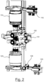
- Fig. 1 shows parts of one phase of a selector switch for a multi-phase tap changer of the column type.
- a main vacuum interrupter (VI) 110 and a resistor vacuum interrupter (VI) 120 are mounted and arranged opposed to one another, such that their respective movable contact ends face each other.
- Their movable contacts are oriented to each other, and coaxially mounted with respect to one another.
- the fixed ends of the main VI 110 and the resistor VI 120 are respectively mounted on a supporting frame.
- an actuation device 150 is provided that is configured to commonly actuate the movable contacts of the VIs 110, 120.
- a main sliding arm 115 is provided that extends from the fixed end of the main VI 110.
- a resistor sliding arm 125 is provided that extends from the fixed end of the resistor VI 120.
- Resistor in “resistor sliding arm”, as used herein, is to be understood as a reference term only, in order to distinguish the arms 115 and 125 from each other. It does not imply that the sliding arm 125 itself has a resistive function, but rather that it refers to the resistor-type VI 120.
- the main VI 110, the resistor VI 120, the actuation device 150, the main sliding arm 115, and the resistor sliding arm 125 are members of a central insulation tube (not shown) that is disposed inside an insulation compartment of a stationary insulation tube.
- a drive mechanism (not shown) is configured to rotationally drive the central insulation tube.
- a switching sequence is performed that involves opening the main vacuum interrupter (110) by means of the actuation device (150), moving the main sliding arm (115) from a current tap to a next tap (not shown), closing the main vacuum interrupter (110) by means of the actuation device (150), opening the resistor vacuum interrupter (120) by means of the actuation device (150), moving the resistor sliding arm (125) from a current tap to a next tap, and closing the resistor vacuum interrupter (120) by means of the actuation device (150). Details on the switching according to the switching sequence are discussed below.
- the resistor sliding arm 125 is moved from the current tap to the next tap after a time delay has passed from the movement of the main sliding arm 115 from the current tap to the next tap.
- Figs. 1 and 2 only show one phase of the selector switch; in a typical embodiment, mounted in the insulation tube are three pairs of sliding arms 115, 125, namely, one pair thereof per phase.
- the common insulation tube supports all pairs of vacuum interrupters 110, 120.
- the main sliding contact arm 115 is connected to the main VI 110, fixed on the central insulation tube.
- the resistor sliding contact arm 125 is connected to the resistor VI 120.
- the arms 115, 125, or levers, may also be configured to perform a bi-direction operation.
- the two sliding arms 115, 125 are attached; the respective first arm, or main sliding arm, 115 is connected to the main VI 110; the respective second arm, or resistor sliding arm, 125 is connected to the resistor VI 120 and provides an idle run movement to achieve the time delay in the switching sequence.
- the actuation device 150 further comprises a control cam ring 151.
- the cam ring 151 is made of metal and is configured to provide a rated, or nominal, current; in other words: The cam ring 151 forms an electric terminal.
- the drive mechanism comprises a Geneva drive (not shown).
- the central insulation tube is, on one side thereof, mechanically connected to a Geneva wheel of the Geneva drive, and on the other side thereof, to a bottom part.
- the actuation device 150, or common lever works as a bidirectional guiding system.
- the common lever is controlled by the cam ring 151, e.g. with a grove guiding means or a planar guiding means.
- the contact arms 115, 125 are mounted on the central insulation tube. Three of them, one per each phase, are assigned to operate the respective main VIs 110, and they are fixedly joined to the central insulation tube. Another three of them, one per each phase, are assigned to operate the respective resistor VIs 110, and they are joined to the central insulation tube through intermediation of a movable joint 126.
- the movable joint 126 provides an idle run and thus the time delay in the switching sequence.
- the idle run rotation is defined by the turning angle of the central insulation tube.
- a spring accumulator activates the Geneva wheel of the Geneva drive.
- the central insulation tube starts rotating.
- the main VIs 110 breaks the current.
- the main sliding contact arms 115 change the contact tap.
- the main VIs 110 are closing. Due to the contact transfer of the main sliding contact arms 115, the resistor sliding contact arms 125 each remain at the previous tap first.
- the resistor VIs 120 open and the resistor sliding arms 125 change the tap. Finally, the resistor VIs 120 are closed.
Landscapes
- High-Tension Arc-Extinguishing Switches Without Spraying Means (AREA)
Claims (10)
- Wahlschalter für einen Laststufenschalter, wobei der Wahlschalter Folgendes umfasst:ein stationäres Isolierrohr, das eine Isolierkammer umschließt;ein zentrales Isolierrohr, das innerhalb der Isolierkammer angeordnet ist, wobei das zentrale Isolierrohr pro Phase Folgendes aufweist:einen Haupt-Vakuumunterbrecher (110), der ein Ende mit einem beweglichem Kontakt und ein festes Ende aufweist;einen Widerstand-Vakuumunterbrecher (120), der ein Ende mit einem beweglichem Kontakt und ein festes Ende aufweist; wobeider Haupt-Vakuumunterbrecher (110) und der Widerstand-Vakuumunterbrecher (120) koaxial und einander gegenüberliegend angeordnet sind, sodass ihre jeweiligen Enden mit den beweglichen Kontakten einander zugewandt sind; undzwischen den Enden mit den beweglichen Kontakten der Vakuumunterbrecher eine Betätigungsvorrichtung (150) bereitgestellt ist, die dazu ausgelegt ist, die beweglichen Kontakte der Vakuumunterbrecher gemeinsam zu betätigen;einen Haupt-Schiebearm (115), der sich vom festen Ende des Haupt-Vakuumunterbrechers erstreckt; undeinen Widerstand-Schiebearm (125), der sich vom festen Ende des Widerstand-Vakuumunterbrechers erstreckt;und einen Antriebsmechanismus, der dazu ausgelegt ist, das zentrale Isolierrohr derart drehend anzutreiben, dass durch die Drehung eine Schaltsequenz ausgeführt wird, wobei die Schaltsequenz das Bewegen des Haupt-Schiebearms (115) von einem aktuellen Abgriff zu einem nächsten Abgriff und, nach Ablauf einer Zeitverzögerung, das Bewegen des Widerstand-Schiebearms (125) von einem aktuellen Abgriff zu einem nächsten Abgriff beinhaltet.
- Wahlschalter nach Anspruch 1, wobei der Widerstand-Schiebearm (125) mittels einer beweglichen Verbindung am festen Ende des Widerstand-Vakuumunterbrechers montiert ist, die die Zeitverzögerung in der Schaltsequenz bereitstellt.
- Wahlschalter nach einem der vorhergehenden Ansprüche, wobei die beweglichen Kontakte des Haupt-Vakuumunterbrechers (110) und des Widerstand-Vakuumunterbrechers (120) derart angeordnet sind, dass sie der Betätigungsvorrichtung zugewandt sind.
- Wahlschalter nach Anspruch 3, wobei die beweglichen Kontakte im Wesentlichen auf einer gemeinsamen Achse angeordnet sind.
- Wahlschalter nach einem der vorhergehenden Ansprüche, wobei die Schaltsequenz Folgendes in der angegebenen Reihenfolge beinhaltet:i. Öffnen des Haupt-Vakuumunterbrechers (110) mittels der Betätigungsvorrichtung (150);ii. Bewegen des Haupt-Schiebearms (115) von einem aktuellen Abgriff zu einem nächsten Abgriff;iii. Schließen des Haupt-Vakuumunterbrechers (110) mittels der Betätigungsvorrichtung (150);iv. Öffnen des Widerstand-Vakuumunterbrechers (120) mittels der Betätigungsvorrichtung (150);ii. Bewegen des Widerstand-Schiebearms (125) von einem aktuellen Abgriff zu einem nächsten Abgriff;iii. Schließen des Widerstand-Vakuumunterbrechers (120) mittels der Betätigungsvorrichtung (150).
- Wahlschalter nach einem der vorhergehenden Ansprüche, wobei die Betätigungsvorrichtung einen Steuernockenring (151) umfasst.
- Wahlschalter nach einem der vorhergehenden Ansprüche, wobei der Antriebsmechanismus ein Malteserkreuzgetriebe umfasst, das dazu ausgelegt ist, das zentrale Isolierrohr schrittweise drehend anzutreiben.
- Wahlschalter nach einem der vorhergehenden Ansprüche, wobei die Schaltsequenz gemeinsam für jede Phase ausgeführt wird.
- Laststufenschalter, der den Wahlschalter nach einem der vorhergehenden Ansprüche umfasst.
- Leistungstransformator mit einem Laststufenschalter, wobei der Laststufenschalter den Wahlschalter nach einem der Ansprüche 1-8 umfasst.
Priority Applications (1)
| Application Number | Priority Date | Filing Date | Title |
|---|---|---|---|
| EP19182366.5A EP3758036B1 (de) | 2019-06-25 | 2019-06-25 | Wahlschalteranordnung für laststufenschalter |
Applications Claiming Priority (1)
| Application Number | Priority Date | Filing Date | Title |
|---|---|---|---|
| EP19182366.5A EP3758036B1 (de) | 2019-06-25 | 2019-06-25 | Wahlschalteranordnung für laststufenschalter |
Publications (2)
| Publication Number | Publication Date |
|---|---|
| EP3758036A1 EP3758036A1 (de) | 2020-12-30 |
| EP3758036B1 true EP3758036B1 (de) | 2024-07-31 |
Family
ID=67070663
Family Applications (1)
| Application Number | Title | Priority Date | Filing Date |
|---|---|---|---|
| EP19182366.5A Active EP3758036B1 (de) | 2019-06-25 | 2019-06-25 | Wahlschalteranordnung für laststufenschalter |
Country Status (1)
| Country | Link |
|---|---|
| EP (1) | EP3758036B1 (de) |
Citations (2)
| Publication number | Priority date | Publication date | Assignee | Title |
|---|---|---|---|---|
| JP2002124422A (ja) * | 2000-10-13 | 2002-04-26 | Toshiba Corp | 負荷時タップ切換器 |
| CN104952603A (zh) * | 2015-06-03 | 2015-09-30 | 浙江纪元高压电器开关有限公司 | 采用真空灭弧室的调压调容分接开关 |
Family Cites Families (3)
| Publication number | Priority date | Publication date | Assignee | Title |
|---|---|---|---|---|
| JPH0693407B2 (ja) * | 1985-01-08 | 1994-11-16 | 株式会社日立製作所 | 負荷時タツプ切換器 |
| JP2003188031A (ja) * | 2001-12-18 | 2003-07-04 | Toshiba Corp | 負荷時タップ切換器 |
| DE102011113718A1 (de) * | 2011-09-17 | 2013-03-21 | Maschinenfabrik Reinhausen Gmbh | Laststufenschalter |
-
2019
- 2019-06-25 EP EP19182366.5A patent/EP3758036B1/de active Active
Patent Citations (2)
| Publication number | Priority date | Publication date | Assignee | Title |
|---|---|---|---|---|
| JP2002124422A (ja) * | 2000-10-13 | 2002-04-26 | Toshiba Corp | 負荷時タップ切換器 |
| CN104952603A (zh) * | 2015-06-03 | 2015-09-30 | 浙江纪元高压电器开关有限公司 | 采用真空灭弧室的调压调容分接开关 |
Also Published As
| Publication number | Publication date |
|---|---|
| EP3758036A1 (de) | 2020-12-30 |
Similar Documents
| Publication | Publication Date | Title |
|---|---|---|
| KR102038345B1 (ko) | 부하시 탭 절환기 | |
| US9640341B2 (en) | On-load tap changer | |
| AU2017229282B2 (en) | On-load tap changer | |
| EP2689440B1 (de) | Stufenwähler für einen laststufenschalter | |
| CN105580100B (zh) | 有载分接开关、用于电压调节的可调式变压器和用于在可调式变压器中实施转换的方法 | |
| RU2699820C2 (ru) | Переключательное устройство для регулировочного трансформатора, в частности переключатель полярности | |
| KR102509893B1 (ko) | 부하 스테핑 스위치, 부하 스테핑 스위치의 작동 방법 및 부하 스테핑 스위치가 있는 전기 설비 | |
| CN102656652B (zh) | 具有空转元件的分接开关 | |
| EP3024007A1 (de) | Widerstandslastumschalter, verfahren zur steuerung des umschalters und laststufenschalter mit dem umschalter | |
| KR20190045368A (ko) | 온-부하 탭 절환기, 온-부하 탭 절환기가 있는 정류 변압기, 및 온-부하 탭 절환기 연결 방법 | |
| CN106716578B (zh) | 用于可调式变压器的预选器 | |
| EP3758036B1 (de) | Wahlschalteranordnung für laststufenschalter | |
| EP3758035B1 (de) | Einphasiger lastumschalter für säulenartigen laststufenschalter | |
| CN114667584B (zh) | 用于有载分接开关的选择器 | |
| CN114026665B (zh) | 用于有载抽头变换器的多相选择器-预选器装置 | |
| US12469652B2 (en) | On-load tap-changer | |
| EP4404228B1 (de) | Laststufenschalter und verfahren zum betreiben eines laststufenschalters | |
| WO2019064003A1 (en) | CHANGER OF SUPPORT | |
| JP2003109829A (ja) | 負荷時タップ切換器 | |
| JPH10116742A (ja) | 負荷時タップ切換器 | |
| JP2002124422A (ja) | 負荷時タップ切換器 | |
| CN116057658A (zh) | 有载分接开关和用于操纵有载分接开关的方法 | |
| JP2002175749A (ja) | 負荷時タップ切換器 | |
| HK1249962B (en) | On-load tap changer, a method of operating an on-load tap changer and electric system with an on-load tap changer | |
| JP2019102706A (ja) | 負荷時タップ切換装置 |
Legal Events
| Date | Code | Title | Description |
|---|---|---|---|
| PUAI | Public reference made under article 153(3) epc to a published international application that has entered the european phase |
Free format text: ORIGINAL CODE: 0009012 |
|
| STAA | Information on the status of an ep patent application or granted ep patent |
Free format text: STATUS: THE APPLICATION HAS BEEN PUBLISHED |
|
| AK | Designated contracting states |
Kind code of ref document: A1 Designated state(s): AL AT BE BG CH CY CZ DE DK EE ES FI FR GB GR HR HU IE IS IT LI LT LU LV MC MK MT NL NO PL PT RO RS SE SI SK SM TR |
|
| AX | Request for extension of the european patent |
Extension state: BA ME |
|
| STAA | Information on the status of an ep patent application or granted ep patent |
Free format text: STATUS: REQUEST FOR EXAMINATION WAS MADE |
|
| 17P | Request for examination filed |
Effective date: 20210624 |
|
| RBV | Designated contracting states (corrected) |
Designated state(s): AL AT BE BG CH CY CZ DE DK EE ES FI FR GB GR HR HU IE IS IT LI LT LU LV MC MK MT NL NO PL PT RO RS SE SI SK SM TR |
|
| RAP3 | Party data changed (applicant data changed or rights of an application transferred) |
Owner name: HITACHI ENERGY SWITZERLAND AG |
|
| STAA | Information on the status of an ep patent application or granted ep patent |
Free format text: STATUS: EXAMINATION IS IN PROGRESS |
|
| 17Q | First examination report despatched |
Effective date: 20220919 |
|
| P01 | Opt-out of the competence of the unified patent court (upc) registered |
Effective date: 20230527 |
|
| GRAP | Despatch of communication of intention to grant a patent |
Free format text: ORIGINAL CODE: EPIDOSNIGR1 |
|
| STAA | Information on the status of an ep patent application or granted ep patent |
Free format text: STATUS: GRANT OF PATENT IS INTENDED |
|
| INTG | Intention to grant announced |
Effective date: 20231116 |
|
| RAP1 | Party data changed (applicant data changed or rights of an application transferred) |
Owner name: HITACHI ENERGY LTD |
|
| GRAJ | Information related to disapproval of communication of intention to grant by the applicant or resumption of examination proceedings by the epo deleted |
Free format text: ORIGINAL CODE: EPIDOSDIGR1 |
|
| STAA | Information on the status of an ep patent application or granted ep patent |
Free format text: STATUS: EXAMINATION IS IN PROGRESS |
|
| GRAP | Despatch of communication of intention to grant a patent |
Free format text: ORIGINAL CODE: EPIDOSNIGR1 |
|
| STAA | Information on the status of an ep patent application or granted ep patent |
Free format text: STATUS: GRANT OF PATENT IS INTENDED |
|
| INTC | Intention to grant announced (deleted) | ||
| INTG | Intention to grant announced |
Effective date: 20240123 |
|
| GRAS | Grant fee paid |
Free format text: ORIGINAL CODE: EPIDOSNIGR3 |
|
| RIN1 | Information on inventor provided before grant (corrected) |
Inventor name: NIKOLOV, VESELIN Inventor name: MIHAYLOV, ANGEL Inventor name: VASILEV, BORISLAV Inventor name: MANEV, GEORGI Inventor name: KOKEV, TODOR PANTELEEV |
|
| GRAA | (expected) grant |
Free format text: ORIGINAL CODE: 0009210 |
|
| STAA | Information on the status of an ep patent application or granted ep patent |
Free format text: STATUS: THE PATENT HAS BEEN GRANTED |
|
| AK | Designated contracting states |
Kind code of ref document: B1 Designated state(s): AL AT BE BG CH CY CZ DE DK EE ES FI FR GB GR HR HU IE IS IT LI LT LU LV MC MK MT NL NO PL PT RO RS SE SI SK SM TR |
|
| REG | Reference to a national code |
Ref country code: CH Ref legal event code: EP Ref country code: GB Ref legal event code: FG4D |
|
| REG | Reference to a national code |
Ref country code: DE Ref legal event code: R096 Ref document number: 602019056011 Country of ref document: DE |
|
| REG | Reference to a national code |
Ref country code: IE Ref legal event code: FG4D |
|
| REG | Reference to a national code |
Ref country code: LT Ref legal event code: MG9D |
|
| REG | Reference to a national code |
Ref country code: NL Ref legal event code: MP Effective date: 20240731 |
|
| PG25 | Lapsed in a contracting state [announced via postgrant information from national office to epo] |
Ref country code: PT Free format text: LAPSE BECAUSE OF FAILURE TO SUBMIT A TRANSLATION OF THE DESCRIPTION OR TO PAY THE FEE WITHIN THE PRESCRIBED TIME-LIMIT Effective date: 20241202 |
|
| REG | Reference to a national code |
Ref country code: AT Ref legal event code: MK05 Ref document number: 1709290 Country of ref document: AT Kind code of ref document: T Effective date: 20240731 |
|
| PG25 | Lapsed in a contracting state [announced via postgrant information from national office to epo] |
Ref country code: PT Free format text: LAPSE BECAUSE OF FAILURE TO SUBMIT A TRANSLATION OF THE DESCRIPTION OR TO PAY THE FEE WITHIN THE PRESCRIBED TIME-LIMIT Effective date: 20241202 |
|
| PG25 | Lapsed in a contracting state [announced via postgrant information from national office to epo] |
Ref country code: NO Free format text: LAPSE BECAUSE OF FAILURE TO SUBMIT A TRANSLATION OF THE DESCRIPTION OR TO PAY THE FEE WITHIN THE PRESCRIBED TIME-LIMIT Effective date: 20241031 |
|
| PG25 | Lapsed in a contracting state [announced via postgrant information from national office to epo] |
Ref country code: NL Free format text: LAPSE BECAUSE OF FAILURE TO SUBMIT A TRANSLATION OF THE DESCRIPTION OR TO PAY THE FEE WITHIN THE PRESCRIBED TIME-LIMIT Effective date: 20240731 Ref country code: FI Free format text: LAPSE BECAUSE OF FAILURE TO SUBMIT A TRANSLATION OF THE DESCRIPTION OR TO PAY THE FEE WITHIN THE PRESCRIBED TIME-LIMIT Effective date: 20240731 Ref country code: PL Free format text: LAPSE BECAUSE OF FAILURE TO SUBMIT A TRANSLATION OF THE DESCRIPTION OR TO PAY THE FEE WITHIN THE PRESCRIBED TIME-LIMIT Effective date: 20240731 Ref country code: GR Free format text: LAPSE BECAUSE OF FAILURE TO SUBMIT A TRANSLATION OF THE DESCRIPTION OR TO PAY THE FEE WITHIN THE PRESCRIBED TIME-LIMIT Effective date: 20241101 |
|
| PG25 | Lapsed in a contracting state [announced via postgrant information from national office to epo] |
Ref country code: BG Free format text: LAPSE BECAUSE OF FAILURE TO SUBMIT A TRANSLATION OF THE DESCRIPTION OR TO PAY THE FEE WITHIN THE PRESCRIBED TIME-LIMIT Effective date: 20240731 |
|
| PG25 | Lapsed in a contracting state [announced via postgrant information from national office to epo] |
Ref country code: LV Free format text: LAPSE BECAUSE OF FAILURE TO SUBMIT A TRANSLATION OF THE DESCRIPTION OR TO PAY THE FEE WITHIN THE PRESCRIBED TIME-LIMIT Effective date: 20240731 |
|
| PG25 | Lapsed in a contracting state [announced via postgrant information from national office to epo] |
Ref country code: IS Free format text: LAPSE BECAUSE OF FAILURE TO SUBMIT A TRANSLATION OF THE DESCRIPTION OR TO PAY THE FEE WITHIN THE PRESCRIBED TIME-LIMIT Effective date: 20241130 Ref country code: AT Free format text: LAPSE BECAUSE OF FAILURE TO SUBMIT A TRANSLATION OF THE DESCRIPTION OR TO PAY THE FEE WITHIN THE PRESCRIBED TIME-LIMIT Effective date: 20240731 |
|
| PG25 | Lapsed in a contracting state [announced via postgrant information from national office to epo] |
Ref country code: HR Free format text: LAPSE BECAUSE OF FAILURE TO SUBMIT A TRANSLATION OF THE DESCRIPTION OR TO PAY THE FEE WITHIN THE PRESCRIBED TIME-LIMIT Effective date: 20240731 |
|
| PG25 | Lapsed in a contracting state [announced via postgrant information from national office to epo] |
Ref country code: RS Free format text: LAPSE BECAUSE OF FAILURE TO SUBMIT A TRANSLATION OF THE DESCRIPTION OR TO PAY THE FEE WITHIN THE PRESCRIBED TIME-LIMIT Effective date: 20241031 Ref country code: ES Free format text: LAPSE BECAUSE OF FAILURE TO SUBMIT A TRANSLATION OF THE DESCRIPTION OR TO PAY THE FEE WITHIN THE PRESCRIBED TIME-LIMIT Effective date: 20240731 |
|
| PG25 | Lapsed in a contracting state [announced via postgrant information from national office to epo] |
Ref country code: RS Free format text: LAPSE BECAUSE OF FAILURE TO SUBMIT A TRANSLATION OF THE DESCRIPTION OR TO PAY THE FEE WITHIN THE PRESCRIBED TIME-LIMIT Effective date: 20241031 Ref country code: PL Free format text: LAPSE BECAUSE OF FAILURE TO SUBMIT A TRANSLATION OF THE DESCRIPTION OR TO PAY THE FEE WITHIN THE PRESCRIBED TIME-LIMIT Effective date: 20240731 Ref country code: NO Free format text: LAPSE BECAUSE OF FAILURE TO SUBMIT A TRANSLATION OF THE DESCRIPTION OR TO PAY THE FEE WITHIN THE PRESCRIBED TIME-LIMIT Effective date: 20241031 Ref country code: NL Free format text: LAPSE BECAUSE OF FAILURE TO SUBMIT A TRANSLATION OF THE DESCRIPTION OR TO PAY THE FEE WITHIN THE PRESCRIBED TIME-LIMIT Effective date: 20240731 Ref country code: LV Free format text: LAPSE BECAUSE OF FAILURE TO SUBMIT A TRANSLATION OF THE DESCRIPTION OR TO PAY THE FEE WITHIN THE PRESCRIBED TIME-LIMIT Effective date: 20240731 Ref country code: IS Free format text: LAPSE BECAUSE OF FAILURE TO SUBMIT A TRANSLATION OF THE DESCRIPTION OR TO PAY THE FEE WITHIN THE PRESCRIBED TIME-LIMIT Effective date: 20241130 Ref country code: HR Free format text: LAPSE BECAUSE OF FAILURE TO SUBMIT A TRANSLATION OF THE DESCRIPTION OR TO PAY THE FEE WITHIN THE PRESCRIBED TIME-LIMIT Effective date: 20240731 Ref country code: GR Free format text: LAPSE BECAUSE OF FAILURE TO SUBMIT A TRANSLATION OF THE DESCRIPTION OR TO PAY THE FEE WITHIN THE PRESCRIBED TIME-LIMIT Effective date: 20241101 Ref country code: FI Free format text: LAPSE BECAUSE OF FAILURE TO SUBMIT A TRANSLATION OF THE DESCRIPTION OR TO PAY THE FEE WITHIN THE PRESCRIBED TIME-LIMIT Effective date: 20240731 Ref country code: ES Free format text: LAPSE BECAUSE OF FAILURE TO SUBMIT A TRANSLATION OF THE DESCRIPTION OR TO PAY THE FEE WITHIN THE PRESCRIBED TIME-LIMIT Effective date: 20240731 Ref country code: BG Free format text: LAPSE BECAUSE OF FAILURE TO SUBMIT A TRANSLATION OF THE DESCRIPTION OR TO PAY THE FEE WITHIN THE PRESCRIBED TIME-LIMIT Effective date: 20240731 Ref country code: AT Free format text: LAPSE BECAUSE OF FAILURE TO SUBMIT A TRANSLATION OF THE DESCRIPTION OR TO PAY THE FEE WITHIN THE PRESCRIBED TIME-LIMIT Effective date: 20240731 |
|
| PG25 | Lapsed in a contracting state [announced via postgrant information from national office to epo] |
Ref country code: DK Free format text: LAPSE BECAUSE OF FAILURE TO SUBMIT A TRANSLATION OF THE DESCRIPTION OR TO PAY THE FEE WITHIN THE PRESCRIBED TIME-LIMIT Effective date: 20240731 Ref country code: SM Free format text: LAPSE BECAUSE OF FAILURE TO SUBMIT A TRANSLATION OF THE DESCRIPTION OR TO PAY THE FEE WITHIN THE PRESCRIBED TIME-LIMIT Effective date: 20240731 Ref country code: RO Free format text: LAPSE BECAUSE OF FAILURE TO SUBMIT A TRANSLATION OF THE DESCRIPTION OR TO PAY THE FEE WITHIN THE PRESCRIBED TIME-LIMIT Effective date: 20240731 |
|
| PG25 | Lapsed in a contracting state [announced via postgrant information from national office to epo] |
Ref country code: EE Free format text: LAPSE BECAUSE OF FAILURE TO SUBMIT A TRANSLATION OF THE DESCRIPTION OR TO PAY THE FEE WITHIN THE PRESCRIBED TIME-LIMIT Effective date: 20240731 |
|
| PG25 | Lapsed in a contracting state [announced via postgrant information from national office to epo] |
Ref country code: CZ Free format text: LAPSE BECAUSE OF FAILURE TO SUBMIT A TRANSLATION OF THE DESCRIPTION OR TO PAY THE FEE WITHIN THE PRESCRIBED TIME-LIMIT Effective date: 20240731 |
|
| PG25 | Lapsed in a contracting state [announced via postgrant information from national office to epo] |
Ref country code: SK Free format text: LAPSE BECAUSE OF FAILURE TO SUBMIT A TRANSLATION OF THE DESCRIPTION OR TO PAY THE FEE WITHIN THE PRESCRIBED TIME-LIMIT Effective date: 20240731 Ref country code: IT Free format text: LAPSE BECAUSE OF FAILURE TO SUBMIT A TRANSLATION OF THE DESCRIPTION OR TO PAY THE FEE WITHIN THE PRESCRIBED TIME-LIMIT Effective date: 20240731 |
|
| REG | Reference to a national code |
Ref country code: DE Ref legal event code: R097 Ref document number: 602019056011 Country of ref document: DE |
|
| PLBE | No opposition filed within time limit |
Free format text: ORIGINAL CODE: 0009261 |
|
| STAA | Information on the status of an ep patent application or granted ep patent |
Free format text: STATUS: NO OPPOSITION FILED WITHIN TIME LIMIT |
|
| 26N | No opposition filed |
Effective date: 20250501 |
|
| PGFP | Annual fee paid to national office [announced via postgrant information from national office to epo] |
Ref country code: DE Payment date: 20250618 Year of fee payment: 7 |
|
| PG25 | Lapsed in a contracting state [announced via postgrant information from national office to epo] |
Ref country code: SE Free format text: LAPSE BECAUSE OF FAILURE TO SUBMIT A TRANSLATION OF THE DESCRIPTION OR TO PAY THE FEE WITHIN THE PRESCRIBED TIME-LIMIT Effective date: 20240731 |
|
| REG | Reference to a national code |
Ref country code: CH Ref legal event code: H13 Free format text: ST27 STATUS EVENT CODE: U-0-0-H10-H13 (AS PROVIDED BY THE NATIONAL OFFICE) Effective date: 20260127 |
|
| PG25 | Lapsed in a contracting state [announced via postgrant information from national office to epo] |
Ref country code: MC Free format text: LAPSE BECAUSE OF FAILURE TO SUBMIT A TRANSLATION OF THE DESCRIPTION OR TO PAY THE FEE WITHIN THE PRESCRIBED TIME-LIMIT Effective date: 20240731 |
|
| PG25 | Lapsed in a contracting state [announced via postgrant information from national office to epo] |
Ref country code: LU Free format text: LAPSE BECAUSE OF NON-PAYMENT OF DUE FEES Effective date: 20250625 |
|
| GBPC | Gb: european patent ceased through non-payment of renewal fee |
Effective date: 20250625 |
|
| REG | Reference to a national code |
Ref country code: BE Ref legal event code: MM Effective date: 20250630 |
|
| PG25 | Lapsed in a contracting state [announced via postgrant information from national office to epo] |
Ref country code: GB Free format text: LAPSE BECAUSE OF NON-PAYMENT OF DUE FEES Effective date: 20250625 |
|
| PG25 | Lapsed in a contracting state [announced via postgrant information from national office to epo] |
Ref country code: IE Free format text: LAPSE BECAUSE OF NON-PAYMENT OF DUE FEES Effective date: 20250625 |
|
| PG25 | Lapsed in a contracting state [announced via postgrant information from national office to epo] |
Ref country code: BE Free format text: LAPSE BECAUSE OF NON-PAYMENT OF DUE FEES Effective date: 20250630 |
|
| PG25 | Lapsed in a contracting state [announced via postgrant information from national office to epo] |
Ref country code: FR Free format text: LAPSE BECAUSE OF NON-PAYMENT OF DUE FEES Effective date: 20250630 |
|
| PG25 | Lapsed in a contracting state [announced via postgrant information from national office to epo] |
Ref country code: CH Free format text: LAPSE BECAUSE OF NON-PAYMENT OF DUE FEES Effective date: 20250630 |