EP3757306A1 - Dichtband - Google Patents
Dichtband Download PDFInfo
- Publication number
- EP3757306A1 EP3757306A1 EP20191034.6A EP20191034A EP3757306A1 EP 3757306 A1 EP3757306 A1 EP 3757306A1 EP 20191034 A EP20191034 A EP 20191034A EP 3757306 A1 EP3757306 A1 EP 3757306A1
- Authority
- EP
- European Patent Office
- Prior art keywords
- sealing tape
- foam
- cover layer
- barrier layer
- layer
- Prior art date
- Legal status (The legal status is an assumption and is not a legal conclusion. Google has not performed a legal analysis and makes no representation as to the accuracy of the status listed.)
- Withdrawn
Links
Images


Classifications
-
- E—FIXED CONSTRUCTIONS
- E04—BUILDING
- E04B—GENERAL BUILDING CONSTRUCTIONS; WALLS, e.g. PARTITIONS; ROOFS; FLOORS; CEILINGS; INSULATION OR OTHER PROTECTION OF BUILDINGS
- E04B1/00—Constructions in general; Structures which are not restricted either to walls, e.g. partitions, or floors or ceilings or roofs
- E04B1/62—Insulation or other protection; Elements or use of specified material therefor
- E04B1/66—Sealings
- E04B1/68—Sealings of joints, e.g. expansion joints
- E04B1/6812—Compressable seals of solid form
-
- B—PERFORMING OPERATIONS; TRANSPORTING
- B29—WORKING OF PLASTICS; WORKING OF SUBSTANCES IN A PLASTIC STATE IN GENERAL
- B29D—PRODUCING PARTICULAR ARTICLES FROM PLASTICS OR FROM SUBSTANCES IN A PLASTIC STATE
- B29D99/00—Subject matter not provided for in other groups of this subclass
- B29D99/0053—Producing sealings
-
- B—PERFORMING OPERATIONS; TRANSPORTING
- B65—CONVEYING; PACKING; STORING; HANDLING THIN OR FILAMENTARY MATERIAL
- B65H—HANDLING THIN OR FILAMENTARY MATERIAL, e.g. SHEETS, WEBS, CABLES
- B65H18/00—Winding webs
- B65H18/28—Wound package of webs
-
- E—FIXED CONSTRUCTIONS
- E06—DOORS, WINDOWS, SHUTTERS, OR ROLLER BLINDS IN GENERAL; LADDERS
- E06B—FIXED OR MOVABLE CLOSURES FOR OPENINGS IN BUILDINGS, VEHICLES, FENCES OR LIKE ENCLOSURES IN GENERAL, e.g. DOORS, WINDOWS, BLINDS, GATES
- E06B1/00—Border constructions of openings in walls, floors, or ceilings; Frames to be rigidly mounted in such openings
- E06B1/62—Tightening or covering joints between the border of openings and the frame or between contiguous frames
- E06B1/64—Tightening or covering joints between the border of openings and the frame or between contiguous frames by loosely-inserted means, e.g. strip, resilient tongue
-
- E—FIXED CONSTRUCTIONS
- E06—DOORS, WINDOWS, SHUTTERS, OR ROLLER BLINDS IN GENERAL; LADDERS
- E06B—FIXED OR MOVABLE CLOSURES FOR OPENINGS IN BUILDINGS, VEHICLES, FENCES OR LIKE ENCLOSURES IN GENERAL, e.g. DOORS, WINDOWS, BLINDS, GATES
- E06B1/00—Border constructions of openings in walls, floors, or ceilings; Frames to be rigidly mounted in such openings
- E06B1/62—Tightening or covering joints between the border of openings and the frame or between contiguous frames
- E06B2001/626—Tightening or covering joints between the border of openings and the frame or between contiguous frames comprising expanding foam strips
Definitions
- the present invention relates to a method for producing a sealing tape roll with a plurality of internal barrier layers and a corresponding sealing tape.
- Sealing tapes unwound from rolls of sealing tape are used to seal joints between a frame profile, for example a window or a door, and a building wall, in order to seal the joints against drafts and driving rain.
- a frame profile for example a window or a door
- sealing tapes are compressed into sealing tape rolls for space-saving storage, transport and better handling during assembly.
- the water vapor diffusion resistance of the sealing tape is of particular importance as one of the essential sealing tape properties.
- barrier layers on a side flank of the sealing tape or parallel to a side flank of the sealing tape within the same increase the vapor impermeability of the sealing tape between a room inside and a room outside.
- Such a barrier layer has an increased water vapor diffusion resistance compared to the foam of the sealing tape and is therefore suitable for reducing the water vapor diffusion through the sealing tape.
- a sealing tape with internal barrier layers is for example from the EP 2 990 551 A1 known.
- sealing tape If such a sealing tape is inserted in a joint between a frame element and a masonry, it rests there with an underside on the frame element and with an opposite upper side on the wall section facing the joint.
- the barrier layer on or in the sealing tape extends over the entire joint cross-section from the frame element to the masonry. Consequently, an edge of the barrier layer adjacent to the top of the sealing tape runs along the masonry.
- the masonry usually has a rough to very uneven surface due to the assembly work involved in installing doors or windows.
- the sealing tape which is made of soft foam, can adapt to these unevenness due to its flexibility.
- the at least one barrier layer is relatively streaky and, in particular, the edge of the barrier layer adjoining the masonry section cannot, as a rule, fully adapt to the profile of the masonry section. In such areas there is therefore the formation of gaps between the masonry and the at least one barrier layer, through which a water vapor diffusion takes place essentially unhindered and thus bypasses the barrier layer.
- the water vapor impermeability of the sealing tape is negatively affected or, in the installed state of the sealing tape, in which it is received between the frame element and the masonry, has a lower value than the sealing tape would have if it were completely in contact.
- a sealing tape wound up to form a sealing tape roll which has partial sections of a cover layer on the upper side and / or lower side, which are aligned transversely to the at least one inner barrier layer and cover it.
- the at least one internal barrier layer directly adjoins the section of the cover layer that covers it, so that essentially no unimpeded water vapor diffusion between the barrier layer and the subsection the cover layer is possible.
- the respective sub-section of the covering layer in turn lies flat against the masonry section, whereby the contact area is enlarged in comparison to only one edge of the barrier layer abutting the masonry section.
- the partial section of the cover layer is on the one hand more flexible than a barrier layer arranged perpendicular to it and can therefore adapt better to unevenness in the masonry section.
- the areal contact of a subsection of the covering layer on the masonry section also increases the contact area, which ensures that the subsection is at least partially in contact with the masonry section even with unevenness to which it cannot fully adapt locally.
- Sealing tapes extend much further in their longitudinal direction than in their transverse direction and are therefore usually wound around an axis of rotation to form a sealing tape roll (or intermediate roll) for space-saving storage, which extends parallel to the transverse direction of the sealing tape or the foam barrier layer web.
- the EP 2 990 551 A1 describes, for example, the insertion of strips forming a barrier layer by means of suitable insertion tools into incisions which have previously been made in a foam web.
- EP 2 990 552 A1 and EP 2 990 553 A1 For example, individual foam strips can be provided, at least one of which has a side surface to which a barrier material has been applied. The Foam strips are brought together and connected to one another in such a way that the barrier material is received between two foam strips that are adjacent to one another.
- the EP 2 620 565 A1 that at least one incision is made in a foam web that does not completely sever it, and a V-shaped film is then inserted into such an incision. Further processes are known which can be used here without further ado.
- the cover layer In relation to the foam strips made of soft foam, however, the cover layer also has a relatively high rigidity.
- the soft foam of the foam strips is more flexible and can adapt even better to the profile of the masonry section.
- the cover layer In order to ensure that the sealing tape rests as optimally as possible on the masonry section, the cover layer is therefore divided into sections. It is thereby achieved that an improved adaptation to the masonry profile is possible between the subsections of the cover layer.
- a cover layer that extends over the entire upper side and / or underside of the sealing tape would be too inflexible to ensure contact with the masonry section over the entire width of the sealing tape.
- the foam barrier layer web is wound up to form a roll of sealing tape or an intermediate roll in such a way that the subsections of the cover layer are accommodated flat between the individual turns of the respective roll. If the subsections of the cover layer are arranged on the upper side of the foam barrier layer web, the subsections of a turn adjoin the underside of an adjacent turn. Correspondingly, sections of a turn adjoin the top of an adjacent turn when they are arranged on the underside of the foam barrier layer sheet. The same also applies to sealing tape rolls, which are formed by winding up foam barrier layer strips.
- the covering layer is preferably severed in the longitudinal direction in the region of each foam strip of the plurality of foam strips. As a result, partial sections are formed which each cover a barrier layer, while the sealing tape in the area of each foam strip has sufficient flexibility to adapt to the masonry profile.
- the cutting through of the cover layer takes place in a central area of the respective foam strip, whereby a symmetrical structure of the sealing tape and thus the most uniform possible sealing properties are achieved.
- the middle area is arranged symmetrically between the side flanks of the respective foam strip, the side flanks of the foam strip running parallel to the side flanks of the foam barrier layer web.
- the subsections of the cover layer particularly preferably form strips which are arranged next to one another in the transverse direction and run parallel to one another in the longitudinal direction.
- the subsections are preferably evenly distributed in the transverse direction, that is to say they are each at the same distance from one another.
- the uniformity of the sealing properties is also guaranteed by the defined design of the cover layer.
- the manufacturing process and the properties of the sealing tape are reproducible and the sealing tape properties in the installed state deviate as little as possible from the theoretically determined nominal values.
- the foam barrier layer web comprises a plurality of barrier layers and a partial section of the cover layer at least partially covers at least three foam strips arranged next to one another. If there is a corresponding number of foam strips and barrier layers, further subsections can also be provided which at least partially cover at least three foam strips arranged next to one another. Such a subsection partially covers the two outermost foam strips in the transverse direction and completely covers the foam strip or strips arranged between these two foam strips. In this embodiment, such a section covers at least two barrier layers. This simplifies the production process and can be carried out more reliably, since the cover layer has to be cut through at fewer points. Nevertheless, sufficient flexibility of the sealing tape can be ensured.
- severing the covering layer comprises making at least one incision in the covering layer.
- An incision can be made by means of suitable tools such as cutters, knives, saws, or the like.
- the coated foam barrier sheet will moved in the longitudinal direction relative to these tools.
- the tools are arranged in a fixed position viewed in the longitudinal direction and the foam barrier layer sheet is moved along the tools in the longitudinal direction.
- the at least one incision can only cut through the cover layer without damaging the foam strip underneath.
- the cover layer can be made very thin and a correspondingly small incision depth is difficult to monitor and control, the at least one incision can cut through the cover layer and also penetrate the respective foam strip. In any case, it must be ensured that the penetration of the incision into the foam does not adversely affect the cohesion of the foam barrier layer web in the transverse direction.
- the depth of the at least one incision in the foam strip is therefore a maximum of 1/3, preferably a maximum of 1/5 and more preferably a maximum of 1/10 of the thickness of the foam strip between the top and the bottom of the foam barrier layer sheet.
- the depth of the at least one incision in the respective foam strip is no more than 1 mm or 5 mm. In no case does the at least one incision completely sever the respective foam strip. In order not to adversely affect the sealing properties of the sealing tape either, the depth of the at least one incision in the foam should be made as small as possible.
- the severing of the cover layer in a particularly preferred embodiment comprises the removal of the cover layer in regions between the subsections of the cover layer to be formed.
- the removal of the cover layer in regions can include the melting of the cover layer, the milling of the cover layer or the incision and removal of the cover layer in regions.
- Alternative possibilities for removing the cover layer are conceivable and obvious to the person skilled in the art.
- the cover layer can be removed in certain areas without damaging the foam underneath. Since this makes the process more difficult due to the small thickness of the cover layer, it is also conceivable that the foam of the respective foam strip is also slightly removed in this area. However, the removal of the cover layer in regions also takes place over a certain width. It is therefore particularly important here not to penetrate deeply into the respective foam strip in order not to have an unnecessarily strong negative influence on the sealing properties of the sealing tape. A maximum of 1/3, preferably a maximum of 1/5, more preferably a maximum of 1/10 and even more preferably a maximum of 1/20 of the thickness of the foam strip between the top and the bottom of the foam barrier layer web is removed.
- incisions can be made as described above. Instead of making at least one cut in the cover layer, two incisions in each case are to be made in the longitudinal direction in the area of a foam strip in the cover layer, the area between these two incisions being subsequently removed. If the cover layer is not yet connected to the respective foam strip at the time of removal, the area of the cover layer to be removed can simply be removed. If the cover layer is detachably connected to the respective foam strip at this point in time, the area to be removed can be peeled off. But it is also possible that the cover layer is already firmly connected to the respective foam strip. In this case, the foam should also be removed slightly. For example, the area of the cover layer to be removed is to be lifted and a rotating or reciprocating knife can loosen the connection to the foam strip underneath the area of the cover layer to be removed.
- a ratio of the width of the sections to the width of the foam sections between 1:10 and 1: 2 amounts.
- the width of the partial sections of the cover layer is preferably between 1 mm and 40 mm, more preferably between 2 mm and 35 mm, particularly preferably between 5 mm and 30 mm, and the width of the areas of exposed foam is between 0.1 mm and 60 mm, more preferably between 1 mm and 50 mm, particularly preferably between 5 mm and 30 mm.
- the method comprises joining the cover layer to the foam strips of the foam barrier sheet prior to severing the cover layer.
- the cover layer is thereby fixed and fixed on the foam barrier layer web and, in particular, cannot be undesirably shifted or impaired during the subsequent severing of the cover layer.
- the cover layer When the cover layer is connected to the foam strips of the foam barrier layer web, the cover layer is preferably also connected to the at least one barrier layer.
- the cover layer By connecting the cover layer to the at least one barrier layer it is achieved that the desired impermeability to water vapor is also achieved in the area in which the barrier layer adjoins or meets the respective partial section of the cover layer. The joint between the barrier layer and the partial section of the cover layer is thereby closed and water vapor diffusion through a gap between the barrier layer and the partial section of the cover layer is not possible.
- the method comprises connecting the at least one subsection of the cover layer to the at least one barrier layer which is arranged in the region of the subsection.
- the connection consequently takes place only after the covering layer has been severed to form the subsections.
- the partial sections of the cover layer are connected to the respective barrier layer during the compression of the foam barrier layer web when it is wound up to form a roll of sealing tape or an intermediate roll. The process can therefore be designed flexibly.
- the at least one barrier layer extends from top to bottom through the entire foam barrier sheet. This enables a uniform impermeability to water vapor across the cross-section of the sealing tape.
- the at least one barrier layer can also only extend over part of the foam barrier layer web between the top and the bottom.
- the at least one barrier layer extends between the top and bottom of the foam barrier sheet for at least 50% of the height, more preferably over at least 75% of the height, and more preferably over at least 90% of the height of the foam barrier sheet.
- the cover layer can be formed from the same material as the at least one barrier layer. However, the cover layer can also be formed from a different material than the at least one barrier layer.
- the cover layer is particularly preferably formed from a film-like material or an adhesive, in particular from a film web, a film strip, an adhesive tape strip or an adhesive-like liquid medium. These materials are particularly suitable for realizing the sealing requirements and for applying to and connecting with the foam of the foam strips.
- the barrier layers and / or the cover layer described herein are made of a sheet-like material, e.g. B. formed from a film of polyamide, polyurethane, polypropylene or copolymers thereof.
- the barrier layers and cover layers described herein can also be comprised of an adhesive, e.g. B. a dispersion adhesive, in particular an acrylate adhesive. If several barrier layers are provided, they can be formed from the same material or from different materials.
- the barrier layers and also the cover layers can be designed to be moisture-variable, i.e. H. their water vapor diffusion resistance changes depending on the humidity of the environment. Characteristic of the water vapor diffusion resistance is the water vapor diffusion value based on an air layer thickness in meters, the so-called sD value.
- a layer preferably has an sD value of from 0.05 m to 100 m, more preferably from 0.1 m to 25 m or from 0.2 m to 15 m (at 25% relative humidity (RH)).
- the sD value is checked in accordance with DIN EN ISO 12572. Independently of this or in combination with this, a layer can have an sD value of 0.02 m to 10 m or 0.03 m to 6 m or 0.05 m to 2 m at 72.5% rel.
- the sD value at 25% rel. LF in the range from 1 to 10 m and at 72.5% rel. LF are in the range of 0.1 to 5 m.
- the sD values refer to a temperature of 20 ° C.
- the barrier layers and / or the cover layer preferably consist at least partially of a synthetic, water-swellable polymer.
- Both a barrier layer and a cover layer have a thickness of 1 ⁇ m to 1 mm, preferably a thickness of 1 to 500 ⁇ m or 2 to 250 ⁇ m, particularly preferably in the range of 5 to 100 ⁇ m or 5 to 50 ⁇ m.
- the barrier layers can also be configured in multiple layers, in particular as a multilayer composite layer. At least one layer of at least one further material can be arranged on one or both sides of the functional layer. The one or two further layers, which each partially or completely cover the functional layer, can protect and carry or support it and increase the stability of the barrier layers.
- the individual layers can each consist of the same or different material.
- the layers arranged on one or both sides can in particular be nonwovens, woven fabrics or grids made of inert materials such as polyethylene, polyurethane, polypropylene, polyester, glass fibers or viscose, optionally also perforated films, in particular those made of polyethylene, polyurethane, polypropylene or polyester.
- the layers can generally consist of any suitable material which is present in layer form and preferably does not have any higher sD values than the functional layer.
- the layers arranged on one or both sides can consist of a dispersion adhesive, in particular an acrylate adhesive.
- the air permeability of the barrier layers or barrier layers and the cover layer is preferably in the range of 0.01-50 l / (m 2 s), more preferably in the range of 0.01-20 l / (m 2 s).
- the air permeability is preferably 3-6 l / (m 2 s) or preferably 1-2 l / (m 2 s) or 0.2-0.5 l / (m 2 s) or particularly preferably 0, 1-0.3 l / (m 2 s) according to DIN EN ISO 9237; Test area 100 cm 2 at a measuring pressure (negative pressure) of 1.0 mbar, test device Frank 21443, or is no longer measurable.
- the foam of the sealing tape can be formed from any desired open-cell or closed-cell flexible foam, for example from polyurethane, polyethylene, Polyvinyl chloride or polypropylene, and can be impregnated for delayed recovery after compression.
- the density of such flexible foams is between 20 and 200 kg / m 3 .
- the individual foam strips of the foam barrier layer sheet are preferably made of the same material. Alternatively, the foam strips can be formed from different materials.
- the flexible foam preferably has a compressive strength of more than 2 kPa.
- the compressive strength is preferably more than 2.1 kPa, more preferably more than 2.2 kPa, particularly preferably more than 2.3 kPa.
- the compression hardness is preferably less than 4 kPa, more preferably less than 3.8 kPa and more preferably less than 3.6 kPa.
- the compressive strength is a measure of the strength of the foam. The values given here are based on a compression of 40% compared to the initial height.
- the compression hardness is determined according to DIN EN ISO 3386, CV40 is specified.
- the foam barrier layer web is preferably at least partially and preferably completely impregnated with an impregnating agent for the delayed recovery of the sealing tapes.
- the impregnating agent preferably has an acrylate dispersion.
- the acrylate dispersion has acrylate polymer particles dispersed in a homogeneous phase.
- the foam is impregnated with a weight fraction of acrylate dispersion for delayed recovery in such a way that the sealing tape resets in less than 24 hours from a degree of compression of the sealing tape of approx. 9% to 13% at 20 ° C and 50% relative humidity Has joint closure.
- a foam impregnated for delayed recovery preferably has an air permeability in a range from 50 to 1,000 l / (m 2 s), more preferably between 60 and 600 l / (m 2 s) and particularly preferably between 80 and 400 l / (m 2) s) on.
- the information on air permeability given in the context of this application relates to a determination under the standard conditions of a 10 mm thick piece of foam (completely relaxed) at a measuring negative pressure of 1.0 bar, test area 100 cm 2 ; Frank device 21443; DIN ISO 9237.
- a sealing tape according to the invention has an upper side, a lower side and two side flanks connecting the upper side and the lower side, as well as a longitudinal direction which is aligned parallel to the lower side of the sealing tape.
- the sealing tape comprises a plurality of foam strips arranged side by side in a transverse direction, the transverse direction extending parallel to the underside of the sealing tape and transversely to the longitudinal direction of the sealing tape, as well as at least one barrier layer, a barrier layer being arranged between each two adjacent foam strips.
- the sealing tape further comprises at least one continuous section of a cover layer on the top and / or the bottom of the sealing tape, which partially covers two adjacent foam strips and is connected to the two foam strips.
- a sealing tape which has at least a partial section of a cover layer on the top and / or bottom, which is oriented transversely to the at least one inner barrier layer and covers it.
- the at least one internal barrier layer directly adjoins the section of the cover layer that covers it, so that essentially no unimpeded water vapor diffusion between the barrier layer and the subsection the cover layer is possible.
- the partial section of the covering layer in turn lies flat against the masonry section, as a result of which the contact surface is enlarged in comparison to only one edge of the barrier layer which bears against the masonry section.
- the partial section of the cover layer is on the one hand more flexible than a barrier layer arranged perpendicular to it and can therefore adapt better to unevenness in the masonry section.
- the areal contact of a subsection of the covering layer on the masonry section also increases the contact area, which ensures that the subsection is at least partially in contact with the masonry section even with unevenness to which it cannot fully adapt locally.
- the at least one section of the cover layer is connected to the barrier layer which is arranged in the region of the section. This prevents a gap between the barrier layer and the subsection the cover layer, through which an unhindered water vapor diffusion would be possible.
- Fig. 1 shows the step of providing a foam barrier layer web 2 in an isometric view.
- the foam barrier layer web 2 comprises a plurality of foam strips 4 which are arranged next to one another in a transverse direction Q.
- the foam barrier layer web 2 comprises at least one barrier layer 6, with a barrier layer 6 being arranged between each two adjacent foam strips 4.
- Each barrier layer 6 is preferably connected to both foam strips 4 adjoining it, for example glued or laminated onto them.
- the number of foam strips 4 and barrier layers 6 comprised by the foam barrier layer web 2 can essentially be selected as desired.
- a larger number of foam strips 4 and barrier layers 6 has the result that a plurality of sealing tape rolls can be obtained from the foam barrier layer web 2 at the same time. The more sealing tape rolls that can be produced at once, the more effective the process is.
- the foam barrier layer web 2 has an upper side 8, a lower side 10 and two side flanks 12, 14 connecting the upper side 8 and the lower side 10, as well as a longitudinal direction L, which is aligned parallel to the underside 10 of the foam barrier layer sheet 2 and transverse to the transverse direction Q.
- the foam barrier layer web 2 and the individual foam strips 4 preferably have a substantially rectangular cross section. In a compressed state of the foam, however, the cross-sectional shape can deviate.
- the at least one barrier layer 6 can extend continuously from the bottom 10 to the top 8 of the foam barrier layer web 2 or only partially be provided between the bottom 10 and the top 8. However, in order to achieve the desired sealing effect against water vapor diffusion, the at least one barrier layer 6 extends over at least 50%, preferably at least 75% and even more preferably over at least 90% of the thickness of the foam barrier layer web 2.
- the foam barrier layer web 2 is moved in a conveying direction F which is aligned parallel to the longitudinal direction L of the foam barrier layer web 2.
- the foam strips 4 preferably all have the same width in the transverse direction Q and the same height in a height direction perpendicular to the transverse direction Q and to the longitudinal direction L.
- the foam strips 4 can also be of different widths and / or different heights, for example in order to form a profiled foam barrier layer web.
- a barrier layer 6 can optionally also be arranged on the side surfaces of the outermost foam strips 4 of the foam barrier layer web 2 that form the side flanks 12, 14.
- the EP 2 990 551 A1 describes, for example, the insertion of strips forming a barrier layer 6 by means of suitable insertion tools into incisions which have previously been made in a foam web.
- EP 2 990 552 A1 and EP 2 990 553 A1 For example, individual foam strips can be provided, at least one of which has a side surface to which a barrier material has been applied. The foam strips are then brought together and connected to one another in such a way that the barrier material is arranged between two foam strips that are adjacent to one another.
- the EP 2 620 565 A1 describes the EP 2 620 565 A1 that an incision is made in a foam sheet that does not completely cover it severed, and a V-shaped foil is then inserted into such an incision.
- Alternative methods can easily be used.
- Fig. 2 shows in an isometric view the application of a cover layer 16 to the foam barrier layer web 2 according to FIG Fig. 1 .
- the cover layer 16 is designed as a film web.
- the cover layer 16 is provided on a supply roll 18 and fed to the top side 8 of the foam barrier layer web 2.
- the cover layer or an additional cover layer can also be fed to the underside 10 of the foam barrier layer web 2.
- the covering layer 16 can correspondingly be applied to the upper side 8, the lower side 10 or to the upper side 8 and the lower side 10 of the foam barrier layer web 2.
- the cover layer can consist of an adhesive-like liquid medium which is applied in a known manner to the upper side 8 and / or the lower side 10 of the foam barrier layer web 2, for example by means of corresponding nozzles.
- the cover layer 16 preferably covers the entire side 8, 10 of the foam barrier layer web 2 to which it is applied. It is preferred that the cover layer 16 is connected to the foam strips 4 when it is applied to the foam barrier layer sheet 2.
- the cover layer 16 can also be connected to the barrier layers 6 at the same time.
- the cover layer 16 can be glued onto the foam barrier layer sheet 2.
- the cover layer 16 is either provided with an additional adhesive, designed as an adhesive tape or itself has a certain adhesive effect.
- a film-like cover layer 16 can also be laminated onto the foam barrier layer web 2, the connection taking place under the influence of heat and pressure.
- alternative Methods for applying a cover layer 16 of the type mentioned at the beginning are known to the person skilled in the art and can be used without further ado.
- the foam barrier layer web 2 and the cover layer 16 are moved further in the conveying direction F during the application of the cover layer 16.
- cover layer 16 is cut through in the longitudinal direction L in the region of at least two foam strips 4 and at a distance from each barrier layer 6 adjoining these foam strips 4. This means that the cover layer 16 is severed in an area between the two side flanks of a foam strip 4, the side flanks of each foam strip 4 running parallel to the side flanks 12, 14 of the foam barrier layer web 2.
- partial sections 20 of the cover layer 16 are formed, a partial section 20 of the cover layer 16 at least partially covering at least two adjacent foam strips 4.
- a partial section 20 partially covers exactly two foam strips 4 adjoining one another.
- a subsection 20 of the cover layer 16 consequently covers a barrier layer 6 arranged within the foam barrier layer web 2 between these two foam strips 4. Since the cover layer 16 is cut through in the area of a foam strip 4, the edges of a subsection 20 that run in the longitudinal direction L are located of the cover layer 16 between two adjacent barrier layers 6 and at a distance from them.
- the severing of the covering layer 16 in the longitudinal direction L can generally be achieved by making at least one incision in the covering layer 16 ( Fig. 3 ) or by removing the cover layer 16 in certain areas ( Figures 4 and 5 ) respectively.
- Fig. 3 an embodiment is shown in which the severing of the cover layer 16 in the longitudinal direction L includes making at least one incision 22 in the cover layer 16.
- the cover layer 16 is preferably cut through in the longitudinal direction L in the region of each foam strip 4 of the plurality of foam strips 4.
- the number of incisions 22 then corresponds to the number of foam strips 4. But it is also It is conceivable that fewer incisions 22 are provided than foam strips 4, as can be seen in particular from the following description of preferred embodiments of a sealing tape according to the invention.
- a tool 24 is provided which cuts through the cover layer 16.
- the tool 24 is designed in the shape of a cylinder and has a plurality of circumferential cutting edges.
- other tools e.g. Knives or saws.
- the incisions 22 run parallel to one another in order to also form parallel partial sections 20 of the cover layer 16.
- the subsections 20 of the cover layer 16 are then designed in the form of strips. It is preferred that the at least one incision 22 is only made in the cover layer 16 without damaging the foam of the foam strips 4. However, since this requires a high degree of precision, it can also be desirable for the at least one incision 22 to be made in the cover layer 16 and to penetrate into the respective foam strip 4. This makes the process simpler.
- each incision 22 in the foam strip 4 is as small as possible.
- the depth of each incision 22 in the foam strip 4 is therefore a maximum of 1/5, preferably a maximum of 1/10 and more preferably a maximum of 1/20 of the thickness of the foam strip 4 between the upper side 8 and the lower side 10 of the foam barrier layer sheet 2.
- Particularly preferred each incision 22 does not penetrate deeper than 1 mm to 2 mm into the respective foam strip 4.
- the upper side 8 of the foam barrier layer web 2 is essentially completely covered by the cover layer 16 even after the at least one incision 22 has been made. Nevertheless, the incisions 22 make it possible for the cover layer 16 not to influence the flexibility and resilience of the foam strips 4 over the entire width in the transverse direction Q. Rather, there is some flexibility between the individual sections and thus a better adaptation to the surface of a masonry section of the sealing tape to be produced.
- the severing of the cover layer 16 includes the removal of the cover layer 16 in areas between the subsections 20 of the cover layer 16 to be formed, as in Figures 4 and 5 shown.
- regions 26 of the previously applied cover layer 16 are removed again by the respective tool 24.
- the foam of the foam strips 4 is exposed. This makes it possible that in an installed state of the sealing tape to be produced, the surface of the sealing tape in the areas 26 can also adapt to small unevenness of the masonry section.
- the subsections 20 form parallel strips running in the longitudinal direction L.
- the width of the subsections 20 of the cover layer 16 and of the areas 26 in the transverse direction Q can in principle be selected as desired. It goes without saying that the width of the subsections 20 and the regions 26 influence one another. The wider the partial sections 20 of the cover layer 16, the narrower the areas 26 in which the cover layer 16 has been removed in some areas, and vice versa.
- the sealing tapes to be produced can thus be adapted to the existing requirements or desired properties.
- the tool 24 again has circumferential cutting edges, two cutting edges being arranged at a distance from one another which corresponds to the width of the areas 26 in the transverse direction Q.
- a respective one running in the longitudinal direction L is thereby created Incision made in the cover layer 16.
- the cover layer arranged in this area 26 can then be removed. If the covering layer 16 is only loosely arranged on the foam barrier layer web 2 or is detachably connected to it, the covering layer 16 can simply be removed or peeled off. If the cover layer 16 is firmly connected to the foam barrier layer sheet 2, it may be necessary to use an additional cutting tool to detach the cover layer 16 in the areas 26 from the foam of the foam strips 4 below.
- the tool 24 after Fig. 4 can also have a surface profile, wherein, for example, projections are formed on the circumferential surface of the tool 24, the width of which corresponds to the width of the regions 26. At least these projections can be heated, so that the cover film 16 is melted in the areas 26 and thereby removed. The contours of the subsections 20 of the cover layer 16 are then generally uneven and the subsections 20 do not necessarily form strips running in parallel. The cover layer can also be melted and thereby removed by means of other heat sources, for example by means of a laser.
- Fig. 5 an embodiment of the tool 24 is shown that is suitable for milling off the cover layer in the areas 26.
- the tool 24 is again essentially cylindrical and has a plurality of cutting edges distributed along the circumference, which are spaced from one another in accordance with the distance between the regions 26.
- alternative designs of the tool 24 are readily apparent.
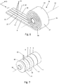
- Fig. 6 shows in an isometric view the step of forming a sealing tape roll 28 according to a first alternative by winding the coated foam barrier layer web 2 around an axis of rotation 30 to form a sealing tape roll 28.
- This first alternative of forming a sealing tape roll 28 is particularly advantageous when the The width of the foam barrier layer web 2 in the transverse direction Q already corresponds to the width of the sealing tape 32 to be produced.
- the foam barrier layer web 2 consequently already has the number of foam strips 4 and barrier layers 6 that are to be produced Sealing tape 32 should have.
- the coated foam barrier layer web 2 is then only to be wound up about the axis of rotation 30, which extends parallel to the transverse direction Q, to form the sealing tape roll 28.
- the method for producing a roll of sealing tape 28 is made particularly simple as a result.
- the foam barrier layer web 2 or the sealing tape 32 is compressed in order to enable space-saving storage. It is conceivable that the necessary pressure is only applied at this point in time in order to connect the cover layer 16 or its subsections 20 to the at least one barrier layer 6.
- the foam barrier layer web 2 or the sealing tape 32 are wound up in such a way that the subsections 20 of the cover layer 16 of one turn of the sealing tape roll 28 lie flat on the underside 10 of the foam barrier layer web 2 or the sealing tape 32 of an adjacent turn.
- the side flanks 12, 14 of the foam barrier layer web 2 form end faces 34, 36 of the sealing tape roll 28.
- an adhesive layer 37 can be applied to the underside 10 of the foam barrier layer web or of the sealing tape before or during the winding up to form the sealing tape roll 28.
- the sealing tape 32 can easily be attached to a frame element by means of the adhesive layer 37.
- the adhesive layer 37 can be formed by a film-shaped or viscous adhesive, e.g. by double-sided tape.
- the adhesive layer 37 is preferably covered by a peel-off layer (not shown), which prevents adjacent turns of the sealing tape roll 28 from sticking and the adhesive layer 37 from being damaged or soiled.
- the adhesive layer 37 is to be applied to the side 8, 10 of the foam barrier layer sheet which is opposite the side 8, 10 which has the cover layer 16. It is also conceivable that the cover layer 16 itself takes on the function of the adhesive layer 37.
- Fig. 7 shows in an isometric view the formation of a sealing tape roll 28 according to a second embodiment by winding the coated foam barrier layer web 2 around an axis of rotation 30 to form an intermediate roller 38 and cutting through the intermediate roller 38 at one or more points in the axial direction to a plurality to produce on sealing tape rolls 28, which are less wide than the intermediate roll 38.
- the sealing tape rolls 28 can have any number of internal barrier layers 6, provided that the foam barrier layer web 2 is dimensioned and designed accordingly. The points of severing the intermediate roller 38 are to be selected accordingly.
- the severing of the intermediate roll 38 can be done by means of a knife 40 or other suitable tools, e.g. by sawing or water jet cutting.
- the foam barrier sheet 2 is also compressed for winding on the intermediate roll 38.
- the connection of the subsections 20 of the cover layer 16 to the barrier layers 6 can only take place at this point in time, if desired.
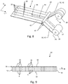
- Fig. 8 shows the step of forming a sealing tape roll 28 according to a third embodiment by severing the coated foam barrier layer web 2 in the longitudinal direction L to form foam barrier layer strips 42 and winding the foam barrier layer strips 42 around an axis of rotation 30 to form individual sealing tape rolls 28.
- To cut through the coated foam barrier layer web 2 at least one cut 44 is made in it, which completely cuts through the foam barrier layer web 2 in order to form a plurality of foam barrier layer strips 42 arranged next to one another in the transverse direction Q.
- the cut 44 is made, for example, by means of a knife 46, alternative means such as sawing or water jet cutting being conceivable here as well.
- the foam barrier layer strips 42 can be compressed in order to then be wound around an axis of rotation 30 to form a sealing tape roller 28 in each case.
- the axis of rotation 30 also extends here parallel to the transverse direction Q. Consequently, a foam barrier layer strip 42 corresponds to a sealing tape 32 and the width of each foam barrier layer strip 42 or the number of foam strips 4 and inner barrier layers 6 must be selected accordingly.
- an additional adhesive layer 37 can be provided in accordance with the above statements.
- FIGs 9 to 12 different embodiments of a sealing tape 32 according to the invention are each shown in a cross-sectional view. Since the width or the number of foam strips 4 and barrier layers 6 of a sealing tape 32 as well as a foam barrier layer web 2 provided for the production of the same can in principle be selected as desired, the following remarks on the Figures 9 to 12 analogously to a foam barrier layer sheet 2 after Figs. 1 to 8 applicable. The referring to the Figures 9 to 12 The features described can therefore be transferred both to such a foam barrier layer web 2 and to the respectively other illustrated embodiments of the sealing tape 32. The features described can in principle be freely combined with one another. The division into the embodiments according to Figures 9 to 12 serves only for a better overview, since not all features are shown in one embodiment. Conceivable combinations of the features described are readily apparent to the person skilled in the art, without having to be specifically mapped for each combination of features.
- a sealing tape 32 has a top side 48, a bottom side 50 and two side flanks 52, 54 connecting the top side 48 and the bottom side 50.
- a sealing band 32 also has a longitudinal direction L, which here is aligned parallel to the underside 50 of the sealing band 32. In the Figures 9 to 12 the longitudinal direction L is aligned perpendicular to the plane of the drawing.
- the upper side 48 and the lower side 50 of the sealing tape 32 correspond to the upper side 8 and the lower side 10 of the foam barrier layer web 2 and the longitudinal direction L of the sealing tape 32 is aligned parallel to the longitudinal direction L of the foam barrier layer web 2.
- Each sealing tape 32 comprises a plurality of foam strips 4 arranged next to one another in the transverse direction Q, the transverse direction Q extending parallel to the underside 50 of the sealing tape 32 and transversely to the longitudinal direction L of the sealing tape 32.
- the sealing tape 32 further comprises at least one barrier layer 6, a barrier layer 6 being arranged between each two adjacent foam strips 4.
- each sealing tape 32 comprises at least one continuous section 20 of a cover layer 16 on the upper side 48 and / or the lower side 50 of the sealing tape 32, which partially covers two adjacent foam strips 4 and is connected to the two foam strips 4.
- the at least one subsection 20 of the cover layer 16 is preferably connected to the barrier layer 6, which is arranged in the region of the respective subsection 20.
- each section 20 covers exactly one barrier layer 6.
- each section 20 is connected to this barrier layer 6, for example glued or laminated.
- each incision 22 or area 26 is thus arranged symmetrically between the side flanks of a foam strip 4, which run parallel to the side flanks 52, 54 of the sealing tape 32.
- each incision 22 or region 26 is also arranged at a distance from a barrier layer 6 in the transverse direction Q in order to ensure that each barrier layer 6 is covered by a section 20 of the cover layer 16.
- the barrier layers 6 preferably extend continuously from the lower side 50 to the upper side 48 of the sealing tape 32 (and thus also continuously from the lower side 10 to the upper side 8 of the foam barrier layer sheet 2). It is also conceivable that the barrier layers 6 extend only partially through the sealing tape 32, for example alternately from the top 48 and the bottom 50, or that part of the barrier layers 6 extend continuously from the bottom 50 to the top 48 of the sealing tape 32 and the remaining barrier layers 6 only partially extend through the sealing tape 32.
- the formation of the barrier layers 6 depends essentially on the method for providing the foam barrier layer web 2 and on the sealing properties required of the sealing tape 32, in particular with regard to the water vapor diffusion resistance.
- a cover layer 16 on the upper side 48 of the sealing tape 32 (or the upper side 8 of the foam barrier layer web 2) and a cover layer 16 on the underside 50 of the sealing tape 32 (or the underside 10 of the foam barrier layer Lane 2) can be arranged.
- the cover layer 16 on the underside 50 can be identical to the cover layer 16 on the top side 48, ie be made of the same material and have subsections 20 which are arranged and formed symmetrically to the subsections 20 of the cover layer 16 on the top side 48.
- the covering layer 16 on the underside 50 can, however, also be different from the covering layer 16 on the upper side 48, for example consist of a different material, have different dimensions or be formed by other means.
- the sealing tape 32 (and thus also the foam barrier layer web 2) comprises a plurality of barrier layers 6 and a section 20 of the cover layer 16 at least partially covers at least three foam strips 4 arranged next to one another. More precisely, a subsection 20 in the embodiment shown completely covers a foam strip 4 and partially covers the foam strips 4 adjoining it on the left and right. Each subsection 20 is preferably connected to all three foam strips 4 that are at least partially covered by it.
- subsections 20 can also cover more than three foam strips 4 in this way.
- Each section 20 partially covers the foam strips 4, which are outermost in the transverse direction Q, of the foam strips 4 covered by it, and completely covers the foam strips 4 arranged between them.
- each partial section 20 of the cover layer 16 covers all the barrier layers 6 which are arranged between the foam strips 4 which it covers.
- the subsections 20 of the cover layer 16 designed in this way can also be cut through of the cover layer 16 by means of at least one incision 22 or by removing the cover layer 16 in regions.
- Fig. 12 an embodiment is shown in which the cover layer 16 has been severed by making at least one incision 22. How out Fig. 12 As can be seen, the incisions 22 also penetrate into the foam of the respective foam strips 4.
- the cohesion of the sealing tape 32 in the transverse direction Q and the sealing properties of the sealing tape 32 are not significantly influenced if the depth of the incisions 22 in the foam strips 4 is small, preferably a maximum of 1 to 2 mm.
- the making of the incisions 22 in the foam of the foam strips 4 should not lead to the sections of the sealing tape 32 formed thereby folding away from one another or the foam strips 4 even being completely severed.
- Such a lack of cohesion in the transverse direction Q reduces the rigidity of the sealing tape 32 in the transverse direction Q and thus worsens the handling of the sealing tape 32.
- a sealing tape 32 is shown schematically.
- the sealing tape 32 is inserted into a joint 58 which is formed between a frame element 60 (for example a window or a door) and a masonry section 62.
- the joint 58 extends from the inside 64 of the room to the outside 66 of the room between the frame element 60 and the masonry section 62.
- the sealing tape 32 is arranged in the joint 58 that the transverse direction Q of the sealing tape 32 is directed from the inside 64 to the outside 66 or the other way around and the longitudinal direction L (perpendicular to the plane of the drawing) runs circumferentially in the joint around the frame element 60.
- the sealing tape 32 is usually fastened to the frame element 60 by means of an adhesive layer 37 on its underside 50 and its top side 48 rests against the masonry section 62.
- the barrier layers 6 extend circumferentially around the frame element 60 in the joint 58, i.e. in the longitudinal direction, and from the frame element 60 to the masonry section 62. In this way, the sealing tape 32 seals the joint 58 in a functional direction X, which is parallel to the transverse direction Q, between the inside 64 and the outside 66 of the room.
- the subsections 20 of the cover layer 16 are arranged on the upper side 48 of the sealing tape 32 and are preferably connected both to the adjoining foam strips 4 and to the at least one adjoining barrier layer 6. This increases the contact surface between the barrier layer 6 and the masonry section 62, which ensures that at least part of the surface of the subsection 20 facing the masonry section 62 rests on the masonry section 62. Since the subsection 20 is still connected to the barrier layer 6, it is achieved that no water vapor diffusion can take place around the barrier layer 6 between an edge thereof and the masonry section 62, but also not between the barrier layer 6 and the respective subsection 20 of the cover layer 16. The water vapor impermeability of the sealing tape 32 is increased.
- the sealing tape 32 can also be arranged in the joint 58 such that the underside 50 of the sealing tape 32 rests on the masonry section 62 and the upper side 48 of the sealing tape 32 rests on the frame element 60.
- both the upper side 48 and the lower side 50 of the sealing tape 32 can be provided with partial sections 20 of a cover layer 16. All other embodiments described herein can analogously be inserted into a corresponding joint.
Landscapes
- Engineering & Computer Science (AREA)
- Civil Engineering (AREA)
- Structural Engineering (AREA)
- Mechanical Engineering (AREA)
- Architecture (AREA)
- Physics & Mathematics (AREA)
- Electromagnetism (AREA)
- Laminated Bodies (AREA)
- Chemical & Material Sciences (AREA)
- Organic Chemistry (AREA)
- Packages (AREA)
Priority Applications (1)
| Application Number | Priority Date | Filing Date | Title |
|---|---|---|---|
| EP20191034.6A EP3757306A1 (de) | 2018-11-07 | 2018-11-07 | Dichtband |
Applications Claiming Priority (2)
| Application Number | Priority Date | Filing Date | Title |
|---|---|---|---|
| EP18204851.2A EP3650608B1 (de) | 2018-11-07 | 2018-11-07 | Verfahren zum herstellen einer dichtbandrolle |
| EP20191034.6A EP3757306A1 (de) | 2018-11-07 | 2018-11-07 | Dichtband |
Related Parent Applications (2)
| Application Number | Title | Priority Date | Filing Date |
|---|---|---|---|
| EP18204851.2A Division-Into EP3650608B1 (de) | 2018-11-07 | 2018-11-07 | Verfahren zum herstellen einer dichtbandrolle |
| EP18204851.2A Division EP3650608B1 (de) | 2018-11-07 | 2018-11-07 | Verfahren zum herstellen einer dichtbandrolle |
Publications (1)
| Publication Number | Publication Date |
|---|---|
| EP3757306A1 true EP3757306A1 (de) | 2020-12-30 |
Family
ID=64183921
Family Applications (2)
| Application Number | Title | Priority Date | Filing Date |
|---|---|---|---|
| EP20191034.6A Withdrawn EP3757306A1 (de) | 2018-11-07 | 2018-11-07 | Dichtband |
| EP18204851.2A Active EP3650608B1 (de) | 2018-11-07 | 2018-11-07 | Verfahren zum herstellen einer dichtbandrolle |
Family Applications After (1)
| Application Number | Title | Priority Date | Filing Date |
|---|---|---|---|
| EP18204851.2A Active EP3650608B1 (de) | 2018-11-07 | 2018-11-07 | Verfahren zum herstellen einer dichtbandrolle |
Country Status (4)
| Country | Link |
|---|---|
| US (1) | US12311628B2 (pl) |
| EP (2) | EP3757306A1 (pl) |
| DK (1) | DK3650608T3 (pl) |
| PL (1) | PL3650608T3 (pl) |
Families Citing this family (2)
| Publication number | Priority date | Publication date | Assignee | Title |
|---|---|---|---|---|
| EP3757081A1 (de) * | 2019-06-27 | 2020-12-30 | Heraeus Quarzglas GmbH & Co. KG | Verfahren zur herstellung eines dreidimensionalen objektes aus glas und dafür geeignete glasfaser |
| DE102020118468A1 (de) | 2020-07-13 | 2022-01-13 | Tremco CPG Germany GmbH | Verfahren zur Herstellung eines Dichtbandes |
Citations (9)
| Publication number | Priority date | Publication date | Assignee | Title |
|---|---|---|---|---|
| DE19955839C1 (de) * | 1999-11-19 | 2001-03-01 | Hilti Ag | Verwendung von quellbare Füllstoffe enthaltenden Kunststoffschäumen zur Abdichtung von Mauerdurchführungen |
| EP2620565A1 (de) | 2012-01-24 | 2013-07-31 | ISO-Chemie GmbH | Dichtband zum Abdichten einer Fuge |
| DE202012101990U1 (de) * | 2012-05-23 | 2013-08-27 | Tremco Illbruck Produktion Gmbh | Dichtband |
| EP2990553A1 (de) | 2014-08-26 | 2016-03-02 | ISO-Chemie GmbH | Verfahren zur Herstellung einer Dichtbandrolle |
| EP2990552A1 (de) | 2014-08-26 | 2016-03-02 | ISO-Chemie GmbH | Verfahren zur Herstellung einer Dichtbandrolle und Dichtbandrolle |
| EP2990551A1 (de) | 2014-08-26 | 2016-03-02 | ISO-Chemie GmbH | Verfahren zur Herstellung einer Dichtbandrolle |
| EP3124712A1 (de) * | 2015-07-30 | 2017-02-01 | Hanno-Werk GmbH & Co. KG | Komprimierbares fugendichtungsband sowie verfahren zur herstellung desselben |
| EP3260617A1 (de) * | 2016-06-20 | 2017-12-27 | tremco illbruck Produktion GmbH | Dichtband |
| EP3346068A1 (de) * | 2017-01-06 | 2018-07-11 | Hanno-Werk GmbH & Co. KG | Schaumstoff sowie fugendichtungsband, umfassend einen solchen schaumstoff |
Family Cites Families (10)
| Publication number | Priority date | Publication date | Assignee | Title |
|---|---|---|---|---|
| DE3544277C1 (de) * | 1985-12-14 | 1987-04-02 | Irbit Res & Consulting Ag | Dichtungsstreifen |
| PL181273B1 (pl) * | 1995-10-23 | 2001-07-31 | Clopay Plastic Products Co | oraz urzadzenie do pasmowego laminowania arkusza wlókninyz wytloczona folia polimerowa PL PL PL PL PL |
| DE19641415C5 (de) | 1996-10-08 | 2017-02-09 | Hanno-Werk Gmbh & Co. Kg | Dichtungsband und Verfahren zur Herstellung des Dichtungsbandes und seine Verwendung |
| AT412700B (de) * | 2001-03-21 | 2005-06-27 | Hirsch Armbaender Ag | Verfahren zur herstellung eines mehrlagigen bandartigen formteiles |
| ATE345925T1 (de) | 2003-03-20 | 2006-12-15 | Blowitex Vliesstoffe Internat | Dichtungsband und verfahren zur herstellung desselben |
| EP2423396B1 (de) * | 2010-08-23 | 2019-11-06 | tremco illbruck GmbH | Schaumstoff-Dichtstreifen |
| DK2990575T3 (da) | 2014-08-26 | 2020-03-02 | Iso Chemie Gmbh | Tætningsbånd til tætning af en fuge |
| PL3453806T5 (pl) * | 2017-09-01 | 2024-01-29 | Iso-Chemie Gmbh | Element uszczelniający |
| DE102018127312A1 (de) | 2018-10-31 | 2020-04-30 | tremco illbruck GmbH | Verfahren zur Herstellung eines Schaumstoffdichtbandes und Schaumstoffdichtband |
| DE202018107177U1 (de) | 2018-09-26 | 2020-01-07 | tremco illbruck GmbH | Dichtband mit Trennschicht |
-
2018
- 2018-11-07 DK DK18204851.2T patent/DK3650608T3/da active
- 2018-11-07 EP EP20191034.6A patent/EP3757306A1/de not_active Withdrawn
- 2018-11-07 PL PL18204851.2T patent/PL3650608T3/pl unknown
- 2018-11-07 EP EP18204851.2A patent/EP3650608B1/de active Active
-
2019
- 2019-10-29 US US16/667,084 patent/US12311628B2/en active Active
Patent Citations (9)
| Publication number | Priority date | Publication date | Assignee | Title |
|---|---|---|---|---|
| DE19955839C1 (de) * | 1999-11-19 | 2001-03-01 | Hilti Ag | Verwendung von quellbare Füllstoffe enthaltenden Kunststoffschäumen zur Abdichtung von Mauerdurchführungen |
| EP2620565A1 (de) | 2012-01-24 | 2013-07-31 | ISO-Chemie GmbH | Dichtband zum Abdichten einer Fuge |
| DE202012101990U1 (de) * | 2012-05-23 | 2013-08-27 | Tremco Illbruck Produktion Gmbh | Dichtband |
| EP2990553A1 (de) | 2014-08-26 | 2016-03-02 | ISO-Chemie GmbH | Verfahren zur Herstellung einer Dichtbandrolle |
| EP2990552A1 (de) | 2014-08-26 | 2016-03-02 | ISO-Chemie GmbH | Verfahren zur Herstellung einer Dichtbandrolle und Dichtbandrolle |
| EP2990551A1 (de) | 2014-08-26 | 2016-03-02 | ISO-Chemie GmbH | Verfahren zur Herstellung einer Dichtbandrolle |
| EP3124712A1 (de) * | 2015-07-30 | 2017-02-01 | Hanno-Werk GmbH & Co. KG | Komprimierbares fugendichtungsband sowie verfahren zur herstellung desselben |
| EP3260617A1 (de) * | 2016-06-20 | 2017-12-27 | tremco illbruck Produktion GmbH | Dichtband |
| EP3346068A1 (de) * | 2017-01-06 | 2018-07-11 | Hanno-Werk GmbH & Co. KG | Schaumstoff sowie fugendichtungsband, umfassend einen solchen schaumstoff |
Also Published As
| Publication number | Publication date |
|---|---|
| US12311628B2 (en) | 2025-05-27 |
| PL3650608T3 (pl) | 2023-11-06 |
| EP3650608B1 (de) | 2023-06-07 |
| EP3650608A1 (de) | 2020-05-13 |
| US20200140723A1 (en) | 2020-05-07 |
| DK3650608T3 (da) | 2023-08-14 |
Similar Documents
| Publication | Publication Date | Title |
|---|---|---|
| EP2990553B1 (de) | Verfahren zur herstellung einer dichtbandrolle | |
| EP3628808B1 (de) | Verfahren zur herstellung eines schaumstoffdichtbandes und schaumstoffdichtband | |
| EP2990552B1 (de) | Verfahren zur herstellung einer dichtbandrolle und dichtbandrolle | |
| EP1983121B1 (de) | Imprägniertes Dichtband mit Einschnitten | |
| EP2990551A1 (de) | Verfahren zur Herstellung einer Dichtbandrolle | |
| EP2620565A1 (de) | Dichtband zum Abdichten einer Fuge | |
| EP3608496B1 (de) | Dichtbandrolle aus einem dichtband mit innenliegenden sperrschichten | |
| EP3825501B1 (de) | Dichtband | |
| EP3450643B1 (de) | Dichtbandrolle | |
| EP3567174B1 (de) | Verfahren zur herstellung von dichtbandrollen | |
| EP3404156B1 (de) | Herstellungsverfahren für dichtband | |
| EP3650608B1 (de) | Verfahren zum herstellen einer dichtbandrolle | |
| EP3608480B1 (de) | Dichtbandrolle aus einem dichtband mit innenliegender sperrschicht in funktionsrichtung | |
| EP3608482B1 (de) | Verfahren zum herstellen einer dichtbandrolle | |
| EP3603941B1 (de) | Herstellungsverfahren für dichtband und dichtband | |
| EP3608481B1 (de) | Dichtbandrolle aus einem dichtband mit innenliegenden sperrschichten | |
| EP3825482B1 (de) | Dichtband | |
| DE102019123970A1 (de) | Eckklebeband | |
| EP3825484A1 (de) | Dichtband | |
| EP3839187A1 (de) | Dichtband |
Legal Events
| Date | Code | Title | Description |
|---|---|---|---|
| PUAI | Public reference made under article 153(3) epc to a published international application that has entered the european phase |
Free format text: ORIGINAL CODE: 0009012 |
|
| STAA | Information on the status of an ep patent application or granted ep patent |
Free format text: STATUS: THE APPLICATION HAS BEEN PUBLISHED |
|
| AC | Divisional application: reference to earlier application |
Ref document number: 3650608 Country of ref document: EP Kind code of ref document: P |
|
| AK | Designated contracting states |
Kind code of ref document: A1 Designated state(s): AL AT BE BG CH CY CZ DE DK EE ES FI FR GB GR HR HU IE IS IT LI LT LU LV MC MK MT NL NO PL PT RO RS SE SI SK SM TR |
|
| STAA | Information on the status of an ep patent application or granted ep patent |
Free format text: STATUS: REQUEST FOR EXAMINATION WAS MADE |
|
| 17P | Request for examination filed |
Effective date: 20210629 |
|
| RBV | Designated contracting states (corrected) |
Designated state(s): AL AT BE BG CH CY CZ DE DK EE ES FI FR GB GR HR HU IE IS IT LI LT LU LV MC MK MT NL NO PL PT RO RS SE SI SK SM TR |
|
| STAA | Information on the status of an ep patent application or granted ep patent |
Free format text: STATUS: EXAMINATION IS IN PROGRESS |
|
| 17Q | First examination report despatched |
Effective date: 20221012 |
|
| STAA | Information on the status of an ep patent application or granted ep patent |
Free format text: STATUS: THE APPLICATION IS DEEMED TO BE WITHDRAWN |
|
| 18D | Application deemed to be withdrawn |
Effective date: 20240907 |