EP1983121B1 - Imprägniertes Dichtband mit Einschnitten - Google Patents
Imprägniertes Dichtband mit Einschnitten Download PDFInfo
- Publication number
- EP1983121B1 EP1983121B1 EP20070007803 EP07007803A EP1983121B1 EP 1983121 B1 EP1983121 B1 EP 1983121B1 EP 20070007803 EP20070007803 EP 20070007803 EP 07007803 A EP07007803 A EP 07007803A EP 1983121 B1 EP1983121 B1 EP 1983121B1
- Authority
- EP
- European Patent Office
- Prior art keywords
- sealing tape
- foam
- incisions
- sealing
- tape according
- Prior art date
- Legal status (The legal status is an assumption and is not a legal conclusion. Google has not performed a legal analysis and makes no representation as to the accuracy of the status listed.)
- Active
Links
Images

Classifications
-
- E—FIXED CONSTRUCTIONS
- E04—BUILDING
- E04B—GENERAL BUILDING CONSTRUCTIONS; WALLS, e.g. PARTITIONS; ROOFS; FLOORS; CEILINGS; INSULATION OR OTHER PROTECTION OF BUILDINGS
- E04B1/00—Constructions in general; Structures which are not restricted either to walls, e.g. partitions, or floors or ceilings or roofs
- E04B1/62—Insulation or other protection; Elements or use of specified material therefor
- E04B1/66—Sealings
- E04B1/68—Sealings of joints, e.g. expansion joints
- E04B1/6812—Compressable seals of solid form
-
- Y—GENERAL TAGGING OF NEW TECHNOLOGICAL DEVELOPMENTS; GENERAL TAGGING OF CROSS-SECTIONAL TECHNOLOGIES SPANNING OVER SEVERAL SECTIONS OF THE IPC; TECHNICAL SUBJECTS COVERED BY FORMER USPC CROSS-REFERENCE ART COLLECTIONS [XRACs] AND DIGESTS
- Y10—TECHNICAL SUBJECTS COVERED BY FORMER USPC
- Y10T—TECHNICAL SUBJECTS COVERED BY FORMER US CLASSIFICATION
- Y10T428/00—Stock material or miscellaneous articles
- Y10T428/24—Structurally defined web or sheet [e.g., overall dimension, etc.]
- Y10T428/24273—Structurally defined web or sheet [e.g., overall dimension, etc.] including aperture
- Y10T428/24322—Composite web or sheet
-
- Y—GENERAL TAGGING OF NEW TECHNOLOGICAL DEVELOPMENTS; GENERAL TAGGING OF CROSS-SECTIONAL TECHNOLOGIES SPANNING OVER SEVERAL SECTIONS OF THE IPC; TECHNICAL SUBJECTS COVERED BY FORMER USPC CROSS-REFERENCE ART COLLECTIONS [XRACs] AND DIGESTS
- Y10—TECHNICAL SUBJECTS COVERED BY FORMER USPC
- Y10T—TECHNICAL SUBJECTS COVERED BY FORMER US CLASSIFICATION
- Y10T428/00—Stock material or miscellaneous articles
- Y10T428/24—Structurally defined web or sheet [e.g., overall dimension, etc.]
- Y10T428/24479—Structurally defined web or sheet [e.g., overall dimension, etc.] including variation in thickness
- Y10T428/24496—Foamed or cellular component
-
- Y—GENERAL TAGGING OF NEW TECHNOLOGICAL DEVELOPMENTS; GENERAL TAGGING OF CROSS-SECTIONAL TECHNOLOGIES SPANNING OVER SEVERAL SECTIONS OF THE IPC; TECHNICAL SUBJECTS COVERED BY FORMER USPC CROSS-REFERENCE ART COLLECTIONS [XRACs] AND DIGESTS
- Y10—TECHNICAL SUBJECTS COVERED BY FORMER USPC
- Y10T—TECHNICAL SUBJECTS COVERED BY FORMER US CLASSIFICATION
- Y10T428/00—Stock material or miscellaneous articles
- Y10T428/249921—Web or sheet containing structurally defined element or component
- Y10T428/249953—Composite having voids in a component [e.g., porous, cellular, etc.]
- Y10T428/249976—Voids specified as closed
Definitions
- the present invention relates to a sealing tape made of soft, compression-recoverable foam for sealing a joint, which is impregnated with an impregnate.
- Such sealing tapes are usually made of polyethylene or polyurethane foam and serve to seal against rain, air, wind, sound or insulation against heat loss.
- the sealing tapes are used in particular in the construction industry, where joints between the window or door frame and the masonry to be sealed.
- the foams consist of a cell structure with cell stems and pores in between.
- the range of flexible foams ranges from closed-cell foams, which provide virtually no air passage, to open-cell foams, which have a relatively high air permeability.
- At least open-celled foams are usually soaked to achieve the desired sealing properties with an impregnate. Such impregnates also lead to a delayed recovery of the foam after its compression, since the impregnates usually contain adhesive substances that attach to the cell webs of the foam structure and adhere there.
- the delayed recovery is often exploited in the sealing of joints by the foam is first compressed and inserted into the joint to be sealed, whereupon the foam expands by itself to a part-expanded functional state and closes the joint.
- the impregnate can also achieve other positive properties, such as fire protection properties or protection against UV radiation.
- DE 1 937 394 A discloses an insulation sheet, in particular insulation panels, insulation sheets or insulation moldings, for example, non-impregnated closed-cell foam. Incisions are made in the insulation track to increase air ventilation and make the foam semipermeable.
- Impregnation with viscous impregnates is difficult to achieve even with open-celled foams. Completely closed-cell foams have so far been virtually impossible to impregnate.
- the present invention is therefore an object of the invention to provide a sealing tape made of soft, recoverable after compression foam, which is impregnated in a particularly simple manner and at the same time achieves enormously high density values.
- a sealing strip of rectangular cross-section of soft, resilient after compression foam for sealing a joint wherein the sealing strip is impregnated with an impregnate and provided with a plurality of cuts, which serve to receive and distribute the impregnate in the foam.
- relatively closed-cell foams can be impregnated more easily and homogeneously, open-cell foams can even be impregnated with viscous impregnates, and even fully closed-cell foams can be provided with an impregnate in the area of the incisions by superficial adhesion, whereby the desired properties such as delayed recovery caused by the impregnate can be achieved are.
- the incisions in the foam are arranged such that they do not affect the seal in the functional direction of the sealing tape or only insignificantly.
- the sealing tape according to the invention has no disadvantages compared to a conventional sealing tape in this respect.
- the extent of the incisions in the longitudinal direction of the sealing strip is at least as great as the extent of the incisions in the transverse direction of the sealing strip.
- the sealing effect in the transverse direction of the sealing band is kept almost constant, while the total area of the incisions in the foam is maximized in the sense of optimum impregnation.
- the cuts are distributed in regular patterns over the foam.
- the incisions extend over the entire height of the sealing strip, whereby the manufacturing process can be made particularly simple.
- the incisions from the top and the bottom of the sealing tape offset from each other are formed to a certain penetration depth in the foam.
- the number of cuts in the foam can be further increased in a simple manner and thus the homogeneity of the impregnation of the foam can be improved.
- the impregnate allows penetration at locations that were previously inaccessible.
- a sealing tape with enormously high sealing values is achieved when the sealing tape according to the invention is formed from a relatively closed-cell foam with low air permeability.
- the impregnate improves the sealing properties of the sealing tape and has tacky properties which result in delayed recovery of the sealing tape after its compression, resulting in easier handling of the sealing tape in the building sector.
- the incisions are preferably formed as displacement cuts.
- Fig. 1 a shows a plan view of a first embodiment of a sealing tape according to the invention.
- the sealing band consists of a soft foam 2, which may be formed of a relatively open-cell foam material with high air permeability, but preferably consists of a relatively closed-cell foam material with low air permeability and small pore cross-sections. Even foams with air penetration values, which lie between the two extreme cases mentioned above, can be used in the context of the present invention.
- Preferred foams are polyurethane or polyethylene foams, which recover completely or almost completely to their original state after compression.
- the expansion of the sealing tape is in Fig. 1 a not faithfully reproduced, since the sealing tape usually has a much larger extent in its longitudinal direction and is wound into a roll. So far Fig. 1a merely as a section of the sealing tape according to the invention to look in the longitudinal direction.
- Fig. 1a In the top view Fig. 1a can be seen many incisions 4a, which here introduced into staggered longitudinal rows in the foam 2, preferably were cut. As from the in Fig. 1b illustrated cross section along line II Fig. 1a it can be seen, in this particular embodiment, the incisions 4a are continuously formed over the entire height of the foam 2, thus establishing a connection between the top 6 and the bottom 8 of the sealing strip.
- the distance between two longitudinal rows of incisions 4a is usually between 1 and 5 mm, as is the distance between two punctiform incisions 4a within a longitudinal row. With wide sealing tapes or sealing tapes with high height for sealing larger joints, even larger distances can be sufficient to achieve the desired effect.
- an impregnate penetrates particularly easily into interior regions of the foam, so that even highly closed-cell foams 2 can be almost completely homogeneously impregnated.
- the impregnate preferably has sticky properties, so that a delayed recovery of the foam 2 is achieved after its compression.
- the waterproofing and rain-tightness are further increased by the impregnate.
- the impregnate may also have fire-retardant properties and anti-UV properties. Conventional impregnates are e.g.
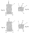
- Fig. 2a and 2b illustrated second embodiment differs from the first embodiment in that the upper cuts 4b, which extend from the top 6 of the foam strip in the foam 2, extend only to about half of the height of the foam 2, while offset this identical cuts 4b protrude from the bottom 8 of the foam 2 in this up to half of the height. This makes it possible to realize lower penetration depths into the foam 2 and to ensure the impregnation of the foam 2 nevertheless.
- a particularly advantageous third embodiment of the sealing tape is in Fig. 3a and 3b shown.
- the difference to the embodiment of Fig. 1a and 1b is that the incisions 4c are extended in the longitudinal direction of the sealing band and thus form strip-shaped longitudinal sections.
- the perforated portion of the foam 2 is increased in the longitudinal direction and achieved an excellent impregnation of the foam 2 with the impregnate.
- the length of the individual strip-shaped longitudinal sections is usually in the range of a few millimeters, but in itself is almost arbitrary and, inter alia, dependent on the dimensions of the foam.
- Fig. 4a and Fig. 4b show a fourth embodiment of the sealing tape according to the invention, which corresponds to the third embodiment, but in which the outgoing from the top 6 of the foam 2 incisions 4d, similar to in Fig. 2b , do not extend to the underside 8 of the foam, and instead project from the bottom 8 of the foam offset from the upper incisions arranged lower incisions 4 d in the foam 2.
- the height of the individual cuts is arbitrary here.
- the incisions can also protrude from only one side, for example the underside 8 of the foam 2, without completely penetrating it (penetration depth preferably between approximately 70 and 99% of the height of the foam), whereby a comb-like structure is formed.
- a self-adhesive strip provided with a cover foil (not shown) is usually applied to the underside 8 for attachment to the component to be sealed. This self-adhesive strip can simultaneously serve to hold together the foam material remaining between the cuts 4a to 4d so that the foam 2 is kept in shape even during compression.
- the structure of the cuts 4a to 4d is variable. Depending on the type of foam, a choice can be made among almost any number of patterns (holes, slits, Z patterns, waves, etc.). However, a greater extent of the incisions in the longitudinal direction is particularly advantageous with respect to the sealing properties of the sealing strip in the transverse direction, which represents the functional direction of the sealing strip.
- the production process of the foam according to the invention preferably proceeds as follows. First, the foam material is produced in large layers, which are then provided with the cuts 4a.
- the introduction of the impregnate takes place preferably by impregnation of the foam layers in a dip bath, wherein multiple compression of the foam layer in addition to the penetration of the impregnate into the incisions leads to a suction effect in the incisions into it. In the area of the incisions, the impregnate penetrates into the nearby cell pores as well as on the upper side 6 and the lower side 8 of the foam and deposits there.
- a self-adhesive layer is applied and the large foam layers are wound in a compressed state onto wide master rolls. These master rolls are severed along with the foam wound thereon at desired intervals, thereby producing narrow-width sealing tape rolls.
- the cuts 4a to 4d are preferably cut by means of suitably shaped knives as displacement cuts in the foam, but it is also conceivable to punch material from the foam or to form the cuts by means of a water jet cutting machine.
- the sealing tape according to the invention thus provides outstanding sealing properties and can be produced in a simple manner.
Landscapes
- Engineering & Computer Science (AREA)
- Architecture (AREA)
- Physics & Mathematics (AREA)
- Electromagnetism (AREA)
- Civil Engineering (AREA)
- Structural Engineering (AREA)
- Sealing Material Composition (AREA)
- Adhesive Tapes (AREA)
Description
- Die vorliegende Erfindung betrifft ein Dichtband aus weichem, nach Kompression rückstellfähigem Schaumstoff zur Abdichtung einer Fuge, das mit einem Imprägnat getränkt ist.
- Derartige Dichtbänder bestehen üblicherweise aus Polyethylen- oder Polyurethanschaumstoff und dienen der Abdichtung gegenüber Regen, Luft, Wind, Schall bzw. der Isolierung gegen Wärmeverlust. Die Dichtbänder kommen insbesondere in der Bauindustrie zum Einsatz, wo Fugen zwischen Fenster- oder Türrahmen und dem Mauerwerk abgedichtet werden sollen. Die Schaumstoffe bestehen aus einer Zellstruktur mit Zellstegen und dazwischen liegenden Poren. Die Skala der Weichschaumstoffe reicht von geschlossenzelligen Schaumstoffen, die nahezu keinen Luftdurchtritt gewähren, bis zu offenzelligen Schaumstoffen, die eine relativ hohe Luftdurchlässigkeit aufweisen. Zumindest offenzellige Schaumstoffe sind in der Regel zum Erzielen der gewünschten Dichteigenschaften mit einem Imprägnat getränkt. Solche Imprägnate führen außerdem auch zu einer verzögerten Rückstellung des Schaumstoffs nach dessen Kompression, da die Imprägnate meist klebende Substanzen enthalten, die sich an den Zellstegen der Schaumstoffstruktur anlagern und dort anhaften. Die verzögerte Rückstellung wird bei der Abdichtung von Fugen oftmals ausgenutzt, indem der Schaumstoff zunächst zusammengedrückt und in die abzudichtende Fuge eingefügt wird, woraufhin sich der Schaumstoff von selbst auf einen teilexpandierten Funktionszustand ausdehnt und die Fuge verschließt. Durch das Imprägnat können auch weitere positive Eigenschaften erreicht werden, beispielsweise Brandschutzeigenschaften oder ein Schutz gegen UV-Strahlung.
-
DE 298 13 307 U1 offenbart ein Dichtband aus imprägniertem Weichschaum mit einer profilierten Oberfläche, wobei die Profilierung der Oberfläche durch Senken und Rippen, die in Längsrichtung des Dichtbandes verlaufen, gebildet wird. Folglich ist der Querschnitt des Dichtbandes durch einen wellenförmigen Profilabschnitt auf der Oberseite gekennzeichnet. -
DE 1 937 394 A offenbart eine Dämmbahn, insbesondere Dämmstoffplatten, Dämmstoffbahnen oder Dämmstoffformkörper, beispielsweise aus nicht imprägniertem geschlossenzelligen Schaumstoff. In die Dämmbahn sind Einschnitte eingebracht, um die Luftventilation zu erhöhen und den Schaumstoff semipermeabel zu machen. - Zur Erzielung von Dichtbändern mit enorm hohen Dichtwerten ist es wünschenswert, auch relativ geschlossenzellige Schaumstoffe zu imprägnieren, wie es in
EP 1 600 571 A1 beschrieben ist. Allerdings ist die vollständige Tränkung von relativ geschlossenzelligen Schaumstoffen sehr aufwändig und hinsichtlich der Wahl des Imprägniermittels eingeschränkt. - Eine Tränkung mit zähflüssigen Imprägnaten ist selbst bei offenzelligen Schaumstoffen schwer zu erreichen. Vollständig geschlossenzellige Schaumstoffe können bislang nahezu überhaupt nicht imprägniert werden.
- Der vorliegenden Erfindung liegt daher die Aufgabe zugrunde, ein Dichtband aus weichem, nach Kompression rückstellfähigem Schaumstoff zu schaffen, das auf besonders einfache Weise imprägniert ist und gleichzeitig enorm hohe Dichtwerte erzielt.
- Diese Aufgabe wird durch die Merkmale des Anspruchs 1 gelöst.
- Demnach ist ein Dichtband rechteckigen Querschnitts aus weichem, nach Kompression rückstellfähigem Schaumstoff zur Abdichtung einer Fuge vorgesehen, wobei das Dichtband mit einem Imprägnat getränkt ist und mit einer Vielzahl von Einschnitten versehen ist, die zur Aufnahme und Verteilung des Imprägnats im Schaumstoff dienen.
- Durch diese Ausgestaltung wird bei allen Schaumstoffarten eine Imprägnierung mit relativ geringem Aufwand möglich. So können beispielsweise relativ geschlossenzellige Schaumstoffe leichter und homogener imprägniert werden, offenzellige Schaumstoffe sogar mit zähflüssigen Imprägnaten getränkt werden und selbst vollständig geschlossenzellige Schaumstoffe im Bereich der Einschnitte durch oberflächliche Anhaftung mit einem Imprägnat versehen werden, wodurch die durch das Imprägnat hervorgerufenen gewünschten Eigenschaften wie verzögerte Rückstellung erzielbar sind.
- Vorzugsweise sind die Einschnitte im Schaumstoff derart angeordnet, dass sie die Abdichtung in Funktionsrichtung des Dichtbands nicht oder nur unwesentlich beeinträchtigen. Somit besitzt das erfindungsgemäße Dichtband gegenüber einem herkömmlichen Dichtband auch in dieser Hinsicht keinerlei Nachteile.
- Vorteilhafterweise Ist die Ausdehnung der Einschnitte in Längsrichtung des Dichtbandes mindestens so groß wie die Ausdehnung der Einschnitte in Querrichtung des Dichtbands. Hierdurch wird der Abdichtungseffekt in Querrichtung des Dichtbands nahezu konstant gehalten, während die Gesamtfläche der Einschnitte im Schaumstoff im Sinne einer optimalen Tränkung maximiert wird.
- Zur einfacheren Fertigung des erfindungsgemäßen Dichtbands sind die Einschnitte in regelmäßigen Mustern über den Schaumstoff verteilt.
- In einer Ausführungsform des erfindungsgemäßen Dichtbands verlaufen die Einschnitte über die gesamte Höhe des Dichtbands, wodurch der Herstellungsprozess besonders einfach gestaltet werden kann.
- In einer anderen Ausführungsform sind die Einschnitte von der Oberseite und der Unterseite des Dichtbands aus zueinander versetzt bis zu einer gewissen Eindringtiefe im Schaumstoff ausgebildet. Dadurch kann die Anzahl von Einschnitten im Schaumstoff auf einfache Weise weiter erhöht und damit die Homogenität der Tränkung des Schaumstoffs verbessert werden. Allgemein gesprochen wird dem Imprägnat das Eindringen an Stellen ermöglicht, die bislang nicht zugänglich waren.
- Ein Dichtband mit enorm hohen Dichtwerten erzielt man, wenn das erfindungsgemäße Dichtband aus einem relativ geschlossenzelligem Schaumstoff mit geringer Luftdurchlässigkeit gebildet ist.
- Vorzugsweise verbessert das Imprägnat die Dichteigenschaften des Dichtbands und weist klebrige Eigenschaften auf, die zu einer verzögerten Rückstellung des Dichtbands nach dessen Kompression führen, was im Baubereich zu einer leichteren Handhabung des Dichtbands führt.
- Um Material zu sparen und gleichzeitig die Dichteigenschaften des Dichtbands in Funktionsrichtung aufrechtzuerhalten, sind die Einschnitte vorzugsweise als Verdrängungsschnitte ausgebildet.
- Weitere Einzelheiten, Merkmale und Vorteile der vorliegenden Erfindung ergeben sich aus der nachfolgenden Beschreibung unter Bezugnahme auf die Zeichnungen.
- Fig. 1 a
- ist eine Draufsicht auf eine erste Ausführungsform des erfindungsgemäßen Dichtbands mit punktförmigen Einschnitten;
- Fig. 16
- ist eine Querschnittsansicht des Dichtbands aus
Fig. 1a entlang der Linie I-I, aus der ersichtlich ist, dass sich die Einschnitte über die gesamte Höhe des Dichtbands erstrecken; - Fig. 2a
- ist eine Draufsicht auf eine zweite Ausführungsform des erfindungsgemäßen Dichtbands mit punktförmigen Einschnitten;
- Fig. 2b
- ist eine Querschnittsansicht des Dichtbands aus
Fig. 2a entlang Linie II-II, aus der ersichtlich ist, dass die Einschnitte sowohl von der Oberseite als auch von der Unterseite des Schaumstoffs zueinander versetzt bis etwa zur halben Höhe des Schaumstoffs reichen; - Fig. 3a
- ist eine Draufsicht auf eine dritte Ausführungsform des erfindungsgemäßen Dichtbands mit sich in Längsrichtung des Dichtbands erstreckenden streifenförmigen Einschnitten;
- Fig. 3b
- ist eine Querschnittsansicht des Dichtbands aus
Fig. 3a entlang Linie III-III, aus der ersichtlich ist, dass sich die Einschnitte über die gesamte Höhe des Schaumstoffs erstrecken; - Fig. 4a
- ist eine Draufsicht auf eine vierte Ausführungsform des erfindungsgemäßen Dichtbands mit sich in Längsrichtung des Dichtbands erstreckenden streifenförmigen Einschnitten; und
- Fig. 4b
- ist eine Querschnittansicht des Dichtbands aus
Fig. 4a entlang Linie IV-IV, aus der ersichtlich ist, dass die Einschnitte sowohl von der Oberseite als auch von der Unterseite des Schaumstoffs zueinander versetzt in den Schaumstoff hineinragen. -
Fig. 1 a zeigt eine Draufsicht auf eine erste Ausführungsform eines erfindungsgemäßen Dichtbands. Das Dichtband besteht aus einem weichen Schaumstoff 2, der aus einem relativ offenzelligen Schaumstoffmaterial mit hoher Luftdurchlässigkeit ausgebildet sein kann, vorzugsweise aber aus einem relativ geschlossenzelligen Schaumstoffmaterial mit geringer Luftdurchlässigkeit und kleinen Porenquerschnitten besteht. Auch Schaumstoffe mit Luftdurchtrittswerten, die zwischen den beiden oben genannten Extremfällen liegen, können im Rahmen der vorliegenden Erfindung verwendet werden. Bevorzugte Schaumstoffe sind Polyurethan- oder Polyethylenschaumstoffe, die sich nach einer Kompression wieder vollständig oder nahezu vollständig in den Ausgangszustand rückstellen. Die Ausdehnung des Dichtbands ist inFig. 1 a nicht naturgetreu wiedergegeben, da das Dichtband üblicherweise in seiner Längsrichtung eine weitaus größere Ausdehnung besitzt und zu einer Rolle aufgewickelt wird. Insofern istFig. 1a lediglich als Ausschnitt des erfindungsgemäßen Dichtbands in Längsrichtung anzusehen. - In der Draufsicht aus
Fig. 1a erkennt man viele Einschnitte 4a, die hier in versetzt zueinander angeordneten Längsreihen in den Schaumstoff 2 eingebracht, vorzugsweise eingeschnitten wurden. Wie aus dem inFig. 1b dargestellten Querschnitt entlang Linie I-I ausFig. 1a ersichtlich ist, sind bei dieser speziellen Ausführungsform die Einschnitte 4a durchgängig über die gesamte Höhe des Schaumstoffs 2 ausgebildet und stellen so eine Verbindung zwischen der Oberseite 6 und der Unterseite 8 des Dichtbands her. Der Abstand zwischen zwei Längsreihen von Einschnitten 4a beträgt üblicherweise zwischen 1 und 5 mm, ebenso der Abstand von zwei punktförmigen Einschnitten 4a innerhalb einer Längsreihe. Bei breiten Dichtbändern oder Dichtbändern mit großer Höhe zum Abdichten für größere Fugen können auch größere Abstände genügen, um den gewünschten Effekt zu erzielen. - Aufgrund der Einschnitte oder Ausnehmungen 4a dringt ein Imprägnat besonders einfach in Innenbereiche des Schaumstoffs ein, so dass selbst hochgradig geschlossenzellige Schaumstoffe 2 nahezu vollständig homogen imprägniert werden können. Das Imprägnat weist vorzugsweise klebrige Eigenschaften auf, so dass eine verzögerte Rückstellung des Schaumstoffs 2 nach dessen Kompression erzielt wird. Außerdem werden durch das Imprägnat die Luft- und Schlagregendichtigkeit noch weiter erhöht. Das lmprägnat kann außerdem brandschutzhemmende Eigenschaften sowie Eigenschaften zum Schutz gegen UV-Strahlung besitzen. Herkömmliche Imprägnate werden z.B. auf Basis von wässrigen Acrylatdispersionen, Polyurethan-Dispersionen, Silikonen, Silikaten, Ethylen-Vinyl-Acetaten, Polyvinylacetaten oder Wachsen hergestellt, es kommen aber auch andere harzhaltige Imprägnate oder weitere bekannte Imprägniermittel, etwa Bitumen, in Frage.
- Die in
Fig. 2a und 2b dargestellte zweite Ausführungsform unterscheidet sich von der ersten Ausführungsform dadurch, dass die oberen Einschnitte 4b, die von der Oberseite 6 des Schaumstoffstreifens aus in den Schaumstoff 2 hineinreichen, sich lediglich bis etwa zur Hälfte der Höhe des Schaumstoffs 2 erstrecken, während versetzt hierzu identische Einschnitte 4b von der Unterseite 8 des Schaumstoffs 2 aus in diesen bis zur Hälfte der Höhe hineinragen. Hierdurch wird es möglich, geringere Einstichtiefen in den Schaumstoff 2 zu realisieren und die Durchtränkung des Schaumstoffs 2 dennoch sicherzustellen. - Eine besonders vorteilhafte dritte Ausführungsform des Dichtbands ist in
Fig. 3a und 3b gezeigt. Der Unterschied zur Ausführungsform vonFig. 1a und 1b liegt darin, dass die Einschnitte 4c in Längsrichtung des Dichtbands ausgedehnt sind und somit streifenförmige Längsschnitte bilden. Hierdurch wird der perforierte Anteil am Schaumstoff 2 in Längsrichtung erhöht und eine hervorragende Tränkung des Schaumstoffs 2 mit dem Imprägnat erzielt. Die Länge der einzelnen streifenförmigen Längsschnitte liegt üblicherweise im Bereich einiger Millimeter, ist an sich aber nahezu beliebig wählbar und u.a. von den Abmessungen des Schaumstoffs abhängig. -
Fig. 4a und Fig. 4b zeigen eine vierte Ausführungsform des erfindungsgemäßen Dichtbands, die der dritten Ausführungsform entspricht, bei der aber die von der Oberseite 6 des Schaumstoffs 2 ausgehenden Einschnitte 4d, ähnlich wie inFig. 2b , nicht bis zur Unterseite 8 des Schaumstoffes reichen, und stattdessen von der Unterseite 8 des Schaumstoffs ausgehend versetzt zu den oberen Einschnitten angeordnete untere Einschnitte 4d in den Schaumstoff 2 hineinragen. Die Höhe der einzelnen Einschnitte ist hierbei beliebig wählbar. - Neben den dargestellten Ausführungsformen sind viele weitere Anordnungen und Einstichtiefen der Einschnitte 4a bis 4d denkbar. Insbesondere können die Einschnitte auch nur von einer Seite, etwa der Unterseite 8 des Schaumstoffs 2, in diesen hineinragen, ohne ihn vollständig zu durchdringen (Eindringtiefe bevorzugt zwischen ca. 70 und 99% der Höhe des Schaumstoffs), wodurch eine kammartige Struktur gebildet wird. Bei allen Dichtbändern ist meistens an der Unterseite 8 ein mit einer Abdeckfolie versehener Selbstklebestreifen (nicht dargestellt) zur Anbringung am abzudichtenden Bauteil aufgebracht. Dieser Selbstklebestreifen kann gleichzeitig dazu dienen, das zwischen den Einschnitten 4a bis 4d verbleibende Schaumstoffmaterial zusammenzuhalten, damit der Schaumstoff 2 auch bei Kompression in Form gehalten wird.
- Die Struktur der Einschnitte 4a bis 4d ist variabel. Je nach Schaumstoffart kann eine Auswahl unter einer nahezu beliebigen Anzahl von Schnittmustern (Löcher, Schlitze, Z-Muster, Wellen etc.) getroffen werden. Eine stärkere Ausdehnung der Einschnitte in Längsrichtung ist jedoch besonders vorteilhaft hinsichtlich der Dichteigenschaften des Dichtbands in Querrichtung, welche die Funktionsrichtung des Dichtbands darstellt.
- Der Herstellungsprozess des erfindungsgemäßen Schaumstoffs verläuft bevorzugt folgendermaßen. Zunächst wird das Schaumstoffmaterial in großen Lagen hergestellt, die anschließend mit den Einschnitten 4a versehen werden. Die Einbringung des Imprägnats erfolgt vorzugsweise durch Tränkung der Schaumstofflagen in einem Tauchbad, wobei eine mehrfache Kompression der Schaumstofflage zusätzlich zum Eindringen des Imprägnats in die Einschnitte zu einem Ansaugeffekt in die Einschnitte hinein führt. Im Bereich der Einschnitte dringt das Imprägnat ebenso wie an der Oberseite 6 und der Unterseite 8 des Schaumstoffs in die nahegelegenen Zellporen vor und lagert sich dort ab. Durch geeignete Wahl der Größe der Einschnitte 4a und des Abstands der Einschnitte zueinander kann somit eine gleichmäßig verteilte Imprägnierung des Schaumstoffmaterials erreicht werden. Nach der Trocknung des imprägnierten Schaumstoffs wird eine Selbstklebeschicht aufgebracht und die großen Schaumstofflagen werden in komprimiertem Zustand auf breite Mutterrollen gewickelt werden. Diese Mutterrollen werden zusammen mit dem darauf aufgewickelten Schaumstoff in gewünschten Abständen durchtrennt, wodurch Dichtbandrollen geringer Breite erzeugt werden.
- Die Einschnitte 4a bis 4d werden vorzugsweise durch geeignet geformte Messer als Verdrängungschnitte in den Schaumstoff geschnitten, es ist allerdings ebenso denkbar, Material aus dem Schaumstoff zu stanzen oder die Einschnitte mittels einer Wasserstrahlschneidemaschine zu bilden.
- Das erfindungsgemäße Dichtband liefert somit herausragende Dichteigenschaften und ist auf einfache Weise herstellbar.
Claims (10)
- Dichtband aus weichem, nach Kompression rückstellfähigem Schaumstoff (2) zur Abdichtung einer Fuge, wobei das Dichtband mit einem Imprägnat getränkt ist,
dadurch gekennzeichnet, dass
das Dichtband einen rechteckigen Querschnitt aufweist und mit einer Vielzahl von Einschnitten (4a, 4b, 4c, 4d) versehen ist, die zur Aufnahme und Verteilung des Imprägnats im Schaumstoff (2) dienen. - Dichtband nach Anspruch 1, dadurch gekennzeichnet, dass es sich entlang einer Längsrichtung erstreckt und für eine Abdichtung in Querrichtung, welche die Funktionsrichtung des Dichtbands darstellt, vorgesehen ist, und dass die Einschnitte (4a, 4b, 4c, 4d) im Schaumstoff (2) derart angeordnet und ausgestaltet sind, dass sie die Abdichtung in Funktionsrichtung nicht oder nur unwesentlich beeinträchtigen.
- Dichtband nach Anspruch 2, dadurch gekennzeichnet, dass die Ausdehnung der Einschnitte (4a, 4b, 4c, 4d) in Längsrichtung mindestens so groß ist wie die Ausdehnung der Einschnitte (4a, 4b, 4c, 4d) in Querrichtung.
- Dichtband nach einem der vorangehenden Ansprüche, dadurch gekennzeichnet, dass die Einschnitte (4a, 4b, 4c, 4d) in regelmäßigen Mustern über den Schaumstoff (2) verteilt sind.
- Dichtband nach einem der vorangehenden Ansprüche, dadurch gekennzeichnet, dass die Einschnitte (4a, 4c) über die gesamte Höhe des Dichtbands verlaufen.
- Dichtband nach einem der Ansprüche 1 bis 4, dadurch gekennzeichnet, dass die Einschnitte (4b, 4d) über einen Teilbereich der Höhe des Dichtbands verlaufen.
- Dichtband nach Anspruch 6, dadurch gekennzeichnet, dass die Einschnitte (4b, 4d) von der Oberseite (6) und der Unterseite (8) des Dichtbands aus zueinander versetzt im Schaumstoff (2) ausgebildet sind.
- Dichtband nach einem der vorangehenden Ansprüche, dadurch gekennzeichnet, dass es aus einem relativ geschlossenzelligen Schaumstoff (2) mit geringer Luft-durchlässigkeit gebildet ist.
- Dichtband nach einem der vorangehenden Ansprüche, dadurch gekennzeichnet, dass das Imprägnat die Dichteigenschaften des Dichtbands verbessert und klebrige Eigenschaften aufweist, die zu einer verzögerten Rückstellung des Dichtbands nach dessen Kompression führen.
- Dichtband nach einem der vorangehenden Ansprüche, dadurch gekennzeichnet, dass die Einschnitte (4a, 4b, 4c, 4d) als Verdrängungsschnitte ausgebildet sind.
Priority Applications (4)
| Application Number | Priority Date | Filing Date | Title |
|---|---|---|---|
| PL07007803T PL1983121T3 (pl) | 2007-04-17 | 2007-04-17 | Impregnowana taśma uszczelniająca z wcięciami |
| DK07007803T DK1983121T3 (da) | 2007-04-17 | 2007-04-17 | Imprægneret tætningsbånd med indsnit |
| EP20070007803 EP1983121B1 (de) | 2007-04-17 | 2007-04-17 | Imprägniertes Dichtband mit Einschnitten |
| US12/103,546 US7897244B2 (en) | 2007-04-17 | 2008-04-15 | Sealing band |
Applications Claiming Priority (1)
| Application Number | Priority Date | Filing Date | Title |
|---|---|---|---|
| EP20070007803 EP1983121B1 (de) | 2007-04-17 | 2007-04-17 | Imprägniertes Dichtband mit Einschnitten |
Publications (2)
| Publication Number | Publication Date |
|---|---|
| EP1983121A1 EP1983121A1 (de) | 2008-10-22 |
| EP1983121B1 true EP1983121B1 (de) | 2013-10-16 |
Family
ID=38110462
Family Applications (1)
| Application Number | Title | Priority Date | Filing Date |
|---|---|---|---|
| EP20070007803 Active EP1983121B1 (de) | 2007-04-17 | 2007-04-17 | Imprägniertes Dichtband mit Einschnitten |
Country Status (4)
| Country | Link |
|---|---|
| US (1) | US7897244B2 (de) |
| EP (1) | EP1983121B1 (de) |
| DK (1) | DK1983121T3 (de) |
| PL (1) | PL1983121T3 (de) |
Cited By (1)
| Publication number | Priority date | Publication date | Assignee | Title |
|---|---|---|---|---|
| DE202014100478U1 (de) | 2014-02-04 | 2015-05-05 | Pinta Abdichtung Gmbh | Dichtband |
Families Citing this family (10)
| Publication number | Priority date | Publication date | Assignee | Title |
|---|---|---|---|---|
| DE102009044558A1 (de) * | 2008-11-17 | 2010-05-20 | Tremco Illbruck Produktion Gmbh | Verfahren zur Abdichtung einer Bauwerksfuge und Dichtelement |
| DE202010005431U1 (de) * | 2010-05-11 | 2011-10-12 | Tremco Illbruck Produktion Gmbh | In eine Bauwerksfuge einbringbares Heizelement und Dichtelement |
| DE202011107000U1 (de) * | 2011-10-21 | 2013-01-29 | Tremco Illbruck Produktion Gmbh | Dichtband |
| DE202012005049U1 (de) * | 2012-05-23 | 2013-08-26 | Tremco Illbruck Produktion Gmbh | Dichtband |
| KR101911902B1 (ko) * | 2012-07-25 | 2018-10-26 | 삼성디스플레이 주식회사 | 충격 흡수 부재 및 이를 포함하는 표시장치 |
| DK179229B1 (en) * | 2015-11-24 | 2018-02-19 | Vkr Holding As | A sealing member for use between a flashing member and a roofing material, a flashing kit including such a sealing member, and a method for weather proofing the joint between a roof of a building and a roof penetrating structure |
| DE102016110665A1 (de) † | 2016-06-09 | 2017-12-14 | Odenwald-Chemie Gmbh | Verbundelement |
| DE102017105323A1 (de) * | 2017-03-14 | 2018-09-20 | Tremco Illbruck Produktion Gmbh | Dichtband und Verfahren zum Herstellen eines Dichtbandes |
| PL3450642T3 (pl) | 2017-09-01 | 2020-06-01 | Iso-Chemie Gmbh | Sposób wytwarzania rolki taśmy uszczelniającej |
| CN109083345A (zh) * | 2018-10-12 | 2018-12-25 | 李铁 | 一种表面贴合安装用隔水条 |
Family Cites Families (5)
| Publication number | Priority date | Publication date | Assignee | Title |
|---|---|---|---|---|
| LU54653A1 (de) * | 1967-10-11 | 1969-07-03 | ||
| DE1937394C3 (de) * | 1969-07-23 | 1974-06-06 | Ruetgerswerke Ag, 6000 Frankfurt | Flächiger Wärmedämmstoff für das Bauwesen |
| CH661761A5 (de) * | 1983-03-16 | 1987-08-14 | Dow Chemical Europ | Randdaemmstreifen zum trennen geheizter schwimmender boeden von der wand in gebaeuden. |
| DE3921777C2 (de) * | 1989-03-16 | 2002-08-29 | Irbit Res & Consulting Ag Frei | Dichtungselement |
| DE29813307U1 (de) * | 1998-07-27 | 1999-12-09 | SALAMANDER INDUSTRIE-PRODUKTE GMBH, 86842 TüRKHEIM | Fugendichtungskörper |
-
2007
- 2007-04-17 DK DK07007803T patent/DK1983121T3/da active
- 2007-04-17 EP EP20070007803 patent/EP1983121B1/de active Active
- 2007-04-17 PL PL07007803T patent/PL1983121T3/pl unknown
-
2008
- 2008-04-15 US US12/103,546 patent/US7897244B2/en not_active Expired - Fee Related
Cited By (1)
| Publication number | Priority date | Publication date | Assignee | Title |
|---|---|---|---|---|
| DE202014100478U1 (de) | 2014-02-04 | 2015-05-05 | Pinta Abdichtung Gmbh | Dichtband |
Also Published As
| Publication number | Publication date |
|---|---|
| PL1983121T3 (pl) | 2014-04-30 |
| US7897244B2 (en) | 2011-03-01 |
| EP1983121A1 (de) | 2008-10-22 |
| DK1983121T3 (da) | 2014-01-27 |
| US20080303226A1 (en) | 2008-12-11 |
Similar Documents
| Publication | Publication Date | Title |
|---|---|---|
| EP1983121B1 (de) | Imprägniertes Dichtband mit Einschnitten | |
| EP3256662B2 (de) | Fugendichtband mit vorbestimmter geometrie und dichtanordnung mit derartigem fugendichtband | |
| EP3256663B1 (de) | Fugendichtband mit vorbestimmter geometrie und dichtanordnung mit derartigem fugendichtband | |
| EP3256666B1 (de) | Universelles fugendichtband für unterschiedliche profildimensionen und dichtanordnung mit derartigem fugendichtband | |
| EP4200493B1 (de) | Dichtvorrichtung für doppelte randfuge sowie trockenbauwand | |
| DE102004042667A1 (de) | Mehrschichtige Gebäudewand | |
| EP2584133B1 (de) | Verfahren zur Abdichtung bei der Fenstersanierung | |
| EP2428632B1 (de) | Dichtband aus weichem Schaumstoff | |
| EP2213811A2 (de) | Schichtverbund als Träger für keramische, Stein- oder ähnliche Beläge | |
| EP2982821B1 (de) | Dichtungselement und verfahren zu seiner herstellung | |
| EP3450643B2 (de) | Dichtbandrolle | |
| EP3825501A1 (de) | Dichtband | |
| EP3856988B1 (de) | Wasserableitendes fugendichtband aus schaumstoff | |
| EP1431473B1 (de) | Dämmplatte für Gebäudefassaden | |
| DE3908063A1 (de) | Verblendelement aus blech | |
| EP3650608B1 (de) | Verfahren zum herstellen einer dichtbandrolle | |
| EP4575114A1 (de) | Fugendichtungsband | |
| DE10008332C1 (de) | Dämmstoffmaterial zum klemmenden Einbau zwischen Begrenzungen | |
| DE102024124916A1 (de) | Aktivierbares Dichtband mit Versteifungsmittel, Verfahren zu dessen Anwendung und zu dessen Herstellung und Baukörper mit einem solchen Dichtband | |
| DE102024124918A1 (de) | Aktivierbares Dichtband mit Versteifungsmittel, Verfahren zu dessen Anwendung und zu dessen Herstellung und Baukörper mit einem solchen Dichtband | |
| DE8903052U1 (de) | Verblendelement aus Blech | |
| DE10008333C2 (de) | Verfahren zum Erstellen einer gedämmten Rahmenkonstruktion sowie Dämmstoffmaterial zur Durchführung des Verfahrens | |
| EP1418279A2 (de) | Noppenbahn zum Abdichten von Bauwerken | |
| HK1242753B (en) | Sealing tape with predetermined geometry and sealing assembly comprising such a sealing tape | |
| AT15928U1 (de) | Fugendichtungsband |
Legal Events
| Date | Code | Title | Description |
|---|---|---|---|
| PUAI | Public reference made under article 153(3) epc to a published international application that has entered the european phase |
Free format text: ORIGINAL CODE: 0009012 |
|
| 17P | Request for examination filed |
Effective date: 20070827 |
|
| AK | Designated contracting states |
Kind code of ref document: A1 Designated state(s): AT BE BG CH CY CZ DE DK EE ES FI FR GB GR HU IE IS IT LI LT LU LV MC MT NL PL PT RO SE SI SK TR |
|
| AX | Request for extension of the european patent |
Extension state: AL BA HR MK RS |
|
| AKX | Designation fees paid |
Designated state(s): AT BE BG CH CY CZ DE DK EE ES FI FR GB GR HU IE IS IT LI LT LU LV MC MT NL PL PT RO SE SI SK TR |
|
| REG | Reference to a national code |
Ref country code: DE Ref legal event code: R079 Ref document number: 502007012376 Country of ref document: DE Free format text: PREVIOUS MAIN CLASS: E04B0001684000 Ipc: E04B0001680000 |
|
| GRAP | Despatch of communication of intention to grant a patent |
Free format text: ORIGINAL CODE: EPIDOSNIGR1 |
|
| RIC1 | Information provided on ipc code assigned before grant |
Ipc: E04B 1/68 20060101AFI20130709BHEP |
|
| INTG | Intention to grant announced |
Effective date: 20130725 |
|
| GRAS | Grant fee paid |
Free format text: ORIGINAL CODE: EPIDOSNIGR3 |
|
| GRAA | (expected) grant |
Free format text: ORIGINAL CODE: 0009210 |
|
| AK | Designated contracting states |
Kind code of ref document: B1 Designated state(s): AT BE BG CH CY CZ DE DK EE ES FI FR GB GR HU IE IS IT LI LT LU LV MC MT NL PL PT RO SE SI SK TR |
|
| REG | Reference to a national code |
Ref country code: GB Ref legal event code: FG4D Free format text: NOT ENGLISH |
|
| REG | Reference to a national code |
Ref country code: CH Ref legal event code: EP |
|
| REG | Reference to a national code |
Ref country code: IE Ref legal event code: FG4D Free format text: LANGUAGE OF EP DOCUMENT: GERMAN |
|
| REG | Reference to a national code |
Ref country code: AT Ref legal event code: REF Ref document number: 636604 Country of ref document: AT Kind code of ref document: T Effective date: 20131115 |
|
| REG | Reference to a national code |
Ref country code: DE Ref legal event code: R096 Ref document number: 502007012376 Country of ref document: DE Effective date: 20131212 |
|
| REG | Reference to a national code |
Ref country code: NL Ref legal event code: T3 |
|
| REG | Reference to a national code |
Ref country code: DK Ref legal event code: T3 Effective date: 20140123 |
|
| REG | Reference to a national code |
Ref country code: LT Ref legal event code: MG4D |
|
| PG25 | Lapsed in a contracting state [announced via postgrant information from national office to epo] |
Ref country code: IS Free format text: LAPSE BECAUSE OF FAILURE TO SUBMIT A TRANSLATION OF THE DESCRIPTION OR TO PAY THE FEE WITHIN THE PRESCRIBED TIME-LIMIT Effective date: 20140216 Ref country code: LT Free format text: LAPSE BECAUSE OF FAILURE TO SUBMIT A TRANSLATION OF THE DESCRIPTION OR TO PAY THE FEE WITHIN THE PRESCRIBED TIME-LIMIT Effective date: 20131016 Ref country code: FI Free format text: LAPSE BECAUSE OF FAILURE TO SUBMIT A TRANSLATION OF THE DESCRIPTION OR TO PAY THE FEE WITHIN THE PRESCRIBED TIME-LIMIT Effective date: 20131016 Ref country code: SE Free format text: LAPSE BECAUSE OF FAILURE TO SUBMIT A TRANSLATION OF THE DESCRIPTION OR TO PAY THE FEE WITHIN THE PRESCRIBED TIME-LIMIT Effective date: 20131016 |
|
| REG | Reference to a national code |
Ref country code: PL Ref legal event code: T3 |
|
| PG25 | Lapsed in a contracting state [announced via postgrant information from national office to epo] |
Ref country code: LV Free format text: LAPSE BECAUSE OF FAILURE TO SUBMIT A TRANSLATION OF THE DESCRIPTION OR TO PAY THE FEE WITHIN THE PRESCRIBED TIME-LIMIT Effective date: 20131016 Ref country code: CY Free format text: LAPSE BECAUSE OF FAILURE TO SUBMIT A TRANSLATION OF THE DESCRIPTION OR TO PAY THE FEE WITHIN THE PRESCRIBED TIME-LIMIT Effective date: 20131016 Ref country code: ES Free format text: LAPSE BECAUSE OF FAILURE TO SUBMIT A TRANSLATION OF THE DESCRIPTION OR TO PAY THE FEE WITHIN THE PRESCRIBED TIME-LIMIT Effective date: 20131016 |
|
| PG25 | Lapsed in a contracting state [announced via postgrant information from national office to epo] |
Ref country code: PT Free format text: LAPSE BECAUSE OF FAILURE TO SUBMIT A TRANSLATION OF THE DESCRIPTION OR TO PAY THE FEE WITHIN THE PRESCRIBED TIME-LIMIT Effective date: 20140217 |
|
| REG | Reference to a national code |
Ref country code: DE Ref legal event code: R097 Ref document number: 502007012376 Country of ref document: DE |
|
| PG25 | Lapsed in a contracting state [announced via postgrant information from national office to epo] |
Ref country code: EE Free format text: LAPSE BECAUSE OF FAILURE TO SUBMIT A TRANSLATION OF THE DESCRIPTION OR TO PAY THE FEE WITHIN THE PRESCRIBED TIME-LIMIT Effective date: 20131016 |
|
| PLBE | No opposition filed within time limit |
Free format text: ORIGINAL CODE: 0009261 |
|
| STAA | Information on the status of an ep patent application or granted ep patent |
Free format text: STATUS: NO OPPOSITION FILED WITHIN TIME LIMIT |
|
| PG25 | Lapsed in a contracting state [announced via postgrant information from national office to epo] |
Ref country code: RO Free format text: LAPSE BECAUSE OF FAILURE TO SUBMIT A TRANSLATION OF THE DESCRIPTION OR TO PAY THE FEE WITHIN THE PRESCRIBED TIME-LIMIT Effective date: 20131016 Ref country code: SK Free format text: LAPSE BECAUSE OF FAILURE TO SUBMIT A TRANSLATION OF THE DESCRIPTION OR TO PAY THE FEE WITHIN THE PRESCRIBED TIME-LIMIT Effective date: 20131016 Ref country code: CZ Free format text: LAPSE BECAUSE OF FAILURE TO SUBMIT A TRANSLATION OF THE DESCRIPTION OR TO PAY THE FEE WITHIN THE PRESCRIBED TIME-LIMIT Effective date: 20131016 |
|
| 26N | No opposition filed |
Effective date: 20140717 |
|
| REG | Reference to a national code |
Ref country code: DE Ref legal event code: R097 Ref document number: 502007012376 Country of ref document: DE Effective date: 20140717 |
|
| PG25 | Lapsed in a contracting state [announced via postgrant information from national office to epo] |
Ref country code: MC Free format text: LAPSE BECAUSE OF FAILURE TO SUBMIT A TRANSLATION OF THE DESCRIPTION OR TO PAY THE FEE WITHIN THE PRESCRIBED TIME-LIMIT Effective date: 20131016 Ref country code: LU Free format text: LAPSE BECAUSE OF FAILURE TO SUBMIT A TRANSLATION OF THE DESCRIPTION OR TO PAY THE FEE WITHIN THE PRESCRIBED TIME-LIMIT Effective date: 20140417 |
|
| REG | Reference to a national code |
Ref country code: IE Ref legal event code: MM4A |
|
| PG25 | Lapsed in a contracting state [announced via postgrant information from national office to epo] |
Ref country code: SI Free format text: LAPSE BECAUSE OF FAILURE TO SUBMIT A TRANSLATION OF THE DESCRIPTION OR TO PAY THE FEE WITHIN THE PRESCRIBED TIME-LIMIT Effective date: 20131016 |
|
| PG25 | Lapsed in a contracting state [announced via postgrant information from national office to epo] |
Ref country code: IE Free format text: LAPSE BECAUSE OF NON-PAYMENT OF DUE FEES Effective date: 20140417 |
|
| PG25 | Lapsed in a contracting state [announced via postgrant information from national office to epo] |
Ref country code: MT Free format text: LAPSE BECAUSE OF FAILURE TO SUBMIT A TRANSLATION OF THE DESCRIPTION OR TO PAY THE FEE WITHIN THE PRESCRIBED TIME-LIMIT Effective date: 20131016 |
|
| REG | Reference to a national code |
Ref country code: FR Ref legal event code: PLFP Year of fee payment: 10 |
|
| PG25 | Lapsed in a contracting state [announced via postgrant information from national office to epo] |
Ref country code: BG Free format text: LAPSE BECAUSE OF FAILURE TO SUBMIT A TRANSLATION OF THE DESCRIPTION OR TO PAY THE FEE WITHIN THE PRESCRIBED TIME-LIMIT Effective date: 20131016 |
|
| PG25 | Lapsed in a contracting state [announced via postgrant information from national office to epo] |
Ref country code: GR Free format text: LAPSE BECAUSE OF FAILURE TO SUBMIT A TRANSLATION OF THE DESCRIPTION OR TO PAY THE FEE WITHIN THE PRESCRIBED TIME-LIMIT Effective date: 20131016 |
|
| PG25 | Lapsed in a contracting state [announced via postgrant information from national office to epo] |
Ref country code: HU Free format text: LAPSE BECAUSE OF FAILURE TO SUBMIT A TRANSLATION OF THE DESCRIPTION OR TO PAY THE FEE WITHIN THE PRESCRIBED TIME-LIMIT; INVALID AB INITIO Effective date: 20070417 Ref country code: TR Free format text: LAPSE BECAUSE OF FAILURE TO SUBMIT A TRANSLATION OF THE DESCRIPTION OR TO PAY THE FEE WITHIN THE PRESCRIBED TIME-LIMIT Effective date: 20131016 |
|
| REG | Reference to a national code |
Ref country code: FR Ref legal event code: PLFP Year of fee payment: 11 |
|
| PGFP | Annual fee paid to national office [announced via postgrant information from national office to epo] |
Ref country code: NL Payment date: 20170424 Year of fee payment: 11 |
|
| PGFP | Annual fee paid to national office [announced via postgrant information from national office to epo] |
Ref country code: DK Payment date: 20170424 Year of fee payment: 11 Ref country code: CH Payment date: 20170424 Year of fee payment: 11 |
|
| PGFP | Annual fee paid to national office [announced via postgrant information from national office to epo] |
Ref country code: IT Payment date: 20170428 Year of fee payment: 11 Ref country code: BE Payment date: 20170424 Year of fee payment: 11 Ref country code: AT Payment date: 20170426 Year of fee payment: 11 Ref country code: PL Payment date: 20170404 Year of fee payment: 11 |
|
| REG | Reference to a national code |
Ref country code: FR Ref legal event code: PLFP Year of fee payment: 12 |
|
| REG | Reference to a national code |
Ref country code: DK Ref legal event code: EBP Effective date: 20180430 |
|
| REG | Reference to a national code |
Ref country code: CH Ref legal event code: PL |
|
| REG | Reference to a national code |
Ref country code: NL Ref legal event code: MM Effective date: 20180501 |
|
| REG | Reference to a national code |
Ref country code: AT Ref legal event code: MM01 Ref document number: 636604 Country of ref document: AT Kind code of ref document: T Effective date: 20180417 |
|
| REG | Reference to a national code |
Ref country code: BE Ref legal event code: MM Effective date: 20180430 |
|
| PG25 | Lapsed in a contracting state [announced via postgrant information from national office to epo] |
Ref country code: AT Free format text: LAPSE BECAUSE OF NON-PAYMENT OF DUE FEES Effective date: 20180417 Ref country code: NL Free format text: LAPSE BECAUSE OF NON-PAYMENT OF DUE FEES Effective date: 20180501 |
|
| PG25 | Lapsed in a contracting state [announced via postgrant information from national office to epo] |
Ref country code: BE Free format text: LAPSE BECAUSE OF NON-PAYMENT OF DUE FEES Effective date: 20180430 Ref country code: CH Free format text: LAPSE BECAUSE OF NON-PAYMENT OF DUE FEES Effective date: 20180430 Ref country code: LI Free format text: LAPSE BECAUSE OF NON-PAYMENT OF DUE FEES Effective date: 20180430 |
|
| PG25 | Lapsed in a contracting state [announced via postgrant information from national office to epo] |
Ref country code: IT Free format text: LAPSE BECAUSE OF NON-PAYMENT OF DUE FEES Effective date: 20180417 |
|
| PG25 | Lapsed in a contracting state [announced via postgrant information from national office to epo] |
Ref country code: DK Free format text: LAPSE BECAUSE OF NON-PAYMENT OF DUE FEES Effective date: 20180430 |
|
| PG25 | Lapsed in a contracting state [announced via postgrant information from national office to epo] |
Ref country code: PL Free format text: LAPSE BECAUSE OF NON-PAYMENT OF DUE FEES Effective date: 20180417 |
|
| PGFP | Annual fee paid to national office [announced via postgrant information from national office to epo] |
Ref country code: DE Payment date: 20250428 Year of fee payment: 19 |
|
| PGFP | Annual fee paid to national office [announced via postgrant information from national office to epo] |
Ref country code: GB Payment date: 20250426 Year of fee payment: 19 |
|
| PGFP | Annual fee paid to national office [announced via postgrant information from national office to epo] |
Ref country code: FR Payment date: 20250426 Year of fee payment: 19 |