EP3757274A1 - Wäschebearbeitungsvorrichtung - Google Patents
Wäschebearbeitungsvorrichtung Download PDFInfo
- Publication number
- EP3757274A1 EP3757274A1 EP20179762.8A EP20179762A EP3757274A1 EP 3757274 A1 EP3757274 A1 EP 3757274A1 EP 20179762 A EP20179762 A EP 20179762A EP 3757274 A1 EP3757274 A1 EP 3757274A1
- Authority
- EP
- European Patent Office
- Prior art keywords
- processing device
- laundry processing
- door
- projector
- projection
- Prior art date
- Legal status (The legal status is an assumption and is not a legal conclusion. Google has not performed a legal analysis and makes no representation as to the accuracy of the status listed.)
- Granted
Links
Images


Classifications
-
- D—TEXTILES; PAPER
- D06—TREATMENT OF TEXTILES OR THE LIKE; LAUNDERING; FLEXIBLE MATERIALS NOT OTHERWISE PROVIDED FOR
- D06F—LAUNDERING, DRYING, IRONING, PRESSING OR FOLDING TEXTILE ARTICLES
- D06F34/00—Details of control systems for washing machines, washer-dryers or laundry dryers
- D06F34/28—Arrangements for program selection, e.g. control panels therefor; Arrangements for indicating program parameters, e.g. the selected program or its progress
- D06F34/34—Arrangements for program selection, e.g. control panels therefor; Arrangements for indicating program parameters, e.g. the selected program or its progress characterised by mounting or attachment features, e.g. detachable control panels or detachable display panels
-
- A—HUMAN NECESSITIES
- A47—FURNITURE; DOMESTIC ARTICLES OR APPLIANCES; COFFEE MILLS; SPICE MILLS; SUCTION CLEANERS IN GENERAL
- A47L—DOMESTIC WASHING OR CLEANING; SUCTION CLEANERS IN GENERAL
- A47L15/00—Washing or rinsing machines for crockery or tableware
- A47L15/42—Details
- A47L15/4293—Arrangements for programme selection, e.g. control panels; Indication of the selected programme, programme progress or other parameters of the programme, e.g. by using display panels
-
- D—TEXTILES; PAPER
- D06—TREATMENT OF TEXTILES OR THE LIKE; LAUNDERING; FLEXIBLE MATERIALS NOT OTHERWISE PROVIDED FOR
- D06F—LAUNDERING, DRYING, IRONING, PRESSING OR FOLDING TEXTILE ARTICLES
- D06F34/00—Details of control systems for washing machines, washer-dryers or laundry dryers
- D06F34/28—Arrangements for program selection, e.g. control panels therefor; Arrangements for indicating program parameters, e.g. the selected program or its progress
- D06F34/32—Arrangements for program selection, e.g. control panels therefor; Arrangements for indicating program parameters, e.g. the selected program or its progress characterised by graphical features, e.g. touchscreens
-
- D—TEXTILES; PAPER
- D06—TREATMENT OF TEXTILES OR THE LIKE; LAUNDERING; FLEXIBLE MATERIALS NOT OTHERWISE PROVIDED FOR
- D06F—LAUNDERING, DRYING, IRONING, PRESSING OR FOLDING TEXTILE ARTICLES
- D06F39/00—Details of washing machines not specific to a single type of machines covered by groups D06F9/00 - D06F27/00
- D06F39/12—Casings; Tubs
- D06F39/14—Doors or covers; Securing means therefor
-
- D—TEXTILES; PAPER
- D06—TREATMENT OF TEXTILES OR THE LIKE; LAUNDERING; FLEXIBLE MATERIALS NOT OTHERWISE PROVIDED FOR
- D06F—LAUNDERING, DRYING, IRONING, PRESSING OR FOLDING TEXTILE ARTICLES
- D06F58/00—Domestic laundry dryers
- D06F58/20—General details of domestic laundry dryers
-
- D—TEXTILES; PAPER
- D06—TREATMENT OF TEXTILES OR THE LIKE; LAUNDERING; FLEXIBLE MATERIALS NOT OTHERWISE PROVIDED FOR
- D06F—LAUNDERING, DRYING, IRONING, PRESSING OR FOLDING TEXTILE ARTICLES
- D06F2105/00—Systems or parameters controlled or affected by the control systems of washing machines, washer-dryers or laundry dryers
- D06F2105/58—Indications or alarms to the control system or to the user
-
- D—TEXTILES; PAPER
- D06—TREATMENT OF TEXTILES OR THE LIKE; LAUNDERING; FLEXIBLE MATERIALS NOT OTHERWISE PROVIDED FOR
- D06F—LAUNDERING, DRYING, IRONING, PRESSING OR FOLDING TEXTILE ARTICLES
- D06F34/00—Details of control systems for washing machines, washer-dryers or laundry dryers
- D06F34/04—Signal transfer or data transmission arrangements
- D06F34/05—Signal transfer or data transmission arrangements for wireless communication between components, e.g. for remote monitoring or control
Definitions
- the invention relates to a laundry processing device according to claim 1, a projection unit for the laundry processing device according to claim 15 and a method with the laundry processing device according to claim 16.
- the object of the invention is in particular to provide a device of the generic type with improved properties with regard to flexibility.
- the object is achieved according to the invention by the features of claims 1, 15 and 16, while advantageous embodiments and developments of the invention can be found in the subclaims.
- a laundry processing device with a laundry processing device, in particular a washing machine, a washer dryer and / or a tumble dryer, with at least one washing and / or drying container for receiving laundry to be processed, with a base body, which has at least one door to limit the washing and / or drying container and with a projection unit, which is provided at least to output at least one image, in particular at least with device information of the laundry processing device, by means of a projection is proposed.
- a projection unit which is provided at least to output at least one image, in particular at least with device information of the laundry processing device, by means of a projection.
- a number of display variants or control panel variants can advantageously be reduced.
- a large number of different sizes of the display and / or the interface can advantageously be made possible, in particular in that a size of the projection output by the projection unit can be varied, for example by means of an objective or the like.
- the display and / or the interface can advantageously be adapted to different situations; for example, the image output by the projection unit could display different content at a point of sale and at an operating location.
- the projection unit can have an advantageously low ratio of energy consumption and achievable display diagonal, especially since a projector only needs a single LED as a light source.
- the projection unit is preferably arranged within the laundry processing device.
- the projection unit in particular a projector of the projection unit, is arranged at least partially outside or completely outside the laundry processing device.
- the projection unit is preferably provided to output the image in such a way that it is projected onto a surface, in particular onto a surface visible from the outside, of the laundry processing device.
- the projection unit is provided to output the image in such a way that it is projected onto a surface that does not belong to the laundry processing device, for example onto a wall, onto a floor or onto a screen specially provided for this purpose.
- the projection unit comprises at least the projector, and that the projector is at least partially integrated into the door, in particular into a door leaf of the door and / or into a frame of the door pivoted with the door leaf.
- a high degree of compactness of the overall construction can thereby advantageously be achieved.
- additional optical coupling elements which are provided to couple an image from a projector from outside the door into the door, can advantageously be dispensed with.
- a simple structure can advantageously be achieved in this way.
- a high degree of flexibility can advantageously be achieved, in particular with regard to the choice of a projector and / or with regard to the replacement of a projector, in particular since access to a door or replacement of a door is far easier than opening the entire device.
- the projection unit and / or the projector can advantageously form its own module, which is particularly easy to assemble or dismantle.
- a display in the door in particular in the area of a window of the door, can advantageously be dispensed with, whereby costs in particular can be kept low.
- a size of a projection of the projector can advantageously be set and / or varied continuously.
- a high degree of flexibility with regard to a display size can advantageously be achieved as a result.
- especially through a modular structure of the door and / or Projection unit can be easily retrofitted to devices that are already in use.
- a “laundry processing device” is to be understood in particular as a washing machine device, a washer dryer device and / or a laundry dryer device which forms at least one part, in particular a subassembly, of a laundry processing device, in particular a washing machine, a washer dryer and / or a clothes dryer.
- the laundry processing device can also comprise the entire laundry processing device.
- a “base body” is to be understood in particular as a part of the laundry processing device which delimits the laundry processing device on the outside.
- the base body preferably forms a housing, preferably including a door, of the laundry processing device.
- a “projection unit” is to be understood as meaning, in particular, a unit, preferably an optical device, which is intended to depict a two-dimensional original on an image surface, in particular by means of a projection.
- the projector has at least one lens.
- the projector has its own light source.
- the projector advantageously only requires a single light source, for example LED.
- a number of LEDs and thus costs can advantageously be kept low.
- a particularly favorable ratio of costs or energy requirements to display size can advantageously be achieved.
- the projector is provided for the purpose of displaying, preferably enlarged, a template generated in particular by means of a Liquid Crystal on Silicon (LCoS) controller.
- LCD Liquid Crystal on Silicon
- the image is designed in particular as a static image or as a moving image.
- the image can be used in particular to display device information and / or to provide operating buttons.
- “Device information” is to be understood as meaning, in particular, information and / or an input request assigned to the laundry processing device.
- the device information can in particular include information about a status, an operating state, an operating progress, an operating mode, an instruction or the like. For example, a remaining time until the current laundry processing operation is completed can be displayed.
- the image is intended to show any display that is also provided by a projection-free control panel of a laundry processing device can be displayed.
- the door is provided in particular to close the washing and / or drying container in a watertight manner. In particular, the door is at least partially and / or partially transparent.
- the door is preferably arranged on a front side of the laundry processing device, in particular designed as a front loader.
- the door can also be arranged, for example, on an upper side of a laundry processing device, in particular designed as a top loader.
- the phrase “integrated into the door” should be understood to mean in particular arranged on and / or preferably in the door.
- the projector is integrated into the door, in particular the door leaf, in such a way that it is moved along with a movement of the door, in particular the door leaf, and is preferably swiveled when the door, in particular the door leaf, is pivoted.
- the projector is fixed in position relative to a frame of the door on the door.
- Provided is to be understood in particular as specifically designed and / or equipped.
- the fact that an object is provided for a specific function should be understood in particular to mean that the object fulfills and / or executes this specific function in at least one application and / or operating state.
- the projector is arranged between an outer frame and an inner frame of a door leaf of the door.
- a particularly high degree of compactness and / or a particularly simple design of the washing device device can advantageously be achieved.
- a particularly advantageous integration of the projector in the door can be achieved.
- the outer frame and the inner frame overlap at least to a large extent in at least one direction, in particular in a direction perpendicular to a visible surface of the door.
- a “major part” should be understood to mean in particular 51%, preferably 66%, preferably 75% and particularly preferably 90%.
- the outer frame and / or the inner frame comprises at least one viewing opening, preferably completely surrounded by the frame in at least one plane, which is provided to accommodate a viewing window.
- a door leaf is to be understood in particular as a movable, preferably pivotable, part of a door.
- the outer frame is arranged on a side of the door facing away from the washing and / or drying container.
- the inner frame is arranged on a side of the door facing the washing and / or drying container.
- the door has a spacer element which is arranged between the outer frame and the inner frame and which forms a receiving space which is provided at least to receive the projector.
- a particularly advantageous integration of the projector in the door can thereby be ensured.
- a particularly high stability of the door can be achieved with the integrated projector.
- the spacer element, the inner frame and / or the outer frame is at least substantially ring-shaped or elliptical.
- the spacer element is intended to be connected at least in a form-fitting manner to the inner frame and / or to the outer frame.
- the spacer element forms at least one stiffening element which is provided to stiffen the door, in particular the door leaf, preferably at least in one plane of the door.
- the outer frame and the spacer element, the inner frame and the spacer element and / or the inner frame and the outer frame touch one another.
- the receiving space is preferably arranged on a side of the spacer element facing the inner frame.
- the projector is preferably arranged on a side of the spacer element facing the inner frame.
- the receiving space can also be arranged on a side of the spacer element facing the outer frame.
- the dimensions and / or shape of the recording space are at least substantially adapted to a shape of the projector.
- the projector be arranged in a lower half of the door.
- a particularly high degree of compactness of the projection unit can thereby advantageously be achieved, in particular in a direction perpendicular to the visible surface of the door.
- an advantageously large projection path can be achieved, whereby the lowest possible complexity of an optical system, in particular a mirror and / or lens system, of the projection unit for guiding the projected image can be achieved.
- the projection unit comprises at least the optical system which is provided to deflect the image output by the projector in such a way that it appears on a front surface of the base body.
- the optical system preferably comprises at least one mirror and / or at least one lens.
- the optics system is provided to deflect a light beam emitted by the projector at least once by at least 90 °.
- a projection direction of the projector which is specified in particular by an emission direction of the lens of the projector, is essentially parallel to a projection plane on which the image projected by the projector is displayed to be visible to an operator.
- Essentially parallel is to be understood here in particular as an alignment of a direction relative to a reference direction, in particular in a plane, the direction having a deviation from the reference direction, in particular less than 8 °, advantageously less than 5 ° and particularly advantageously less than 2 °.
- a “front surface” of the base body is to be understood in particular as the visible surface of the door.
- the visible surface of the door is in particular the surface of the door that is visible from the outside to an operator.
- the image output by the projector is deflected by means of the optics system in such a way that it is led out of the door and appears on a front surface of the base body located outside the door, for example in an area of a control panel of the laundry processing device.
- part of the image output by the projector is deflected by the optical system in such a way that it appears on a front surface of the door and that another part of the image output by the projector is deflected in such a way that it appears on a front surface of the base body appears in an area outside the door, for example in an area of an operating panel of the laundry processing device.
- the optical system is provided to deflect the image output by the projector in such a way that it appears in the window of the door.
- a high degree of flexibility can advantageously be achieved.
- an already existing surface which is advantageously located in an operator's field of vision, can also be used for an image display.
- the viewing pane is designed in particular as an at least substantially transparent pane which is provided to provide a view of the washing and / or drying container, in particular also during active operation of the laundry processing device allow.
- the window is arranged essentially centrally in the door.
- the viewing pane is at least essentially round or elliptical.
- a center of the window is arranged offset slightly upwards relative to a center of the door leaf.
- the optical system comprises at least one projection element which is applied to the viewing window and which is provided to display the image output by the projector, a particularly high light yield of a projection can advantageously be achieved, whereby an energy requirement can advantageously be kept as low as possible.
- the projection element is provided in particular to at least partially absorb the image output by the projector.
- the projection element is preferably glued or welded to the viewing pane.
- the projection element is designed as a rear projection element, in particular a rear projection film, in particular at least partially transparent.
- the optical system can advantageously be designed in a particularly simple manner, in particular since the image can be irradiated from a rear side of a visible surface.
- “Partially transparent” is to be understood as meaning, in particular, with an average transmissivity over all visible light wavelengths of at least 30%, preferably at least 50%, preferably at least 70% and particularly preferably at most 90%.
- the rear projection element is provided to make an image irradiated from a rear side of the rear projection element visible to a viewer on a front side of the rear projection element.
- the rear projection element has a luminance factor (at a viewing angle of 0 °) of at least 1.05, preferably of at least 1.3, preferably of at least 1.5 and particularly preferably of at least 2.
- the rear projection element is designed as a rear projection film made of PVC.
- the optical system is provided to deflect the image output by the projector in such a way that it appears on a front surface of a frame unit of a viewing window of the door, in particular of the door leaf, a high degree of flexibility can advantageously be achieved.
- an already existing area which is advantageously located in an operator's field of vision, can additionally be used for a Image display can be used.
- an unobstructed view of the interior of the washing and / or drying container through the viewing window is advantageously possible.
- the optical system comprises at least the mirror, which is in particular provided at least to deflect the image output by the projector by an angle of at least 50 °, preferably of at least 60 ° and preferably of at least 80 °.
- the mirror is designed in particular as a fully reflecting or as a semitransparent mirror.
- a semitransparent mirror can advantageously enable a view into the interior of the washing and / or drying container through the viewing window and through the semitransparent mirror.
- the semitransparent mirror has a transmission of at least 30%, preferably at least 50% and preferably at least 65%.
- the mirror is designed as an electrically switchable mirror, the transparency and / or reflectivity of which depends on an applied voltage.
- the projection unit have a computing unit which is provided at least to control the projector and which is integrated in the door.
- the computing unit can advantageously form its own module, which is particularly easy to assemble or dismantle.
- the computing unit can advantageously include a memory module which is provided to store various programs which are provided in particular to output information in different languages or in different designs for projection by means of the projector. It is also possible, for example, to output different advertisements for different tasks. For example, an overview of the device specifications or a sales price could be displayed by the projection unit at a point of sale.
- a “computing unit” is to be understood as meaning, in particular, a unit with an information input, information processing and information output.
- the computing unit advantageously has at least one processor, a memory, input and output means, further electrical components, an operating program, control routines, control routines and / or calculation routines.
- the components of the computing unit are preferably arranged on a common circuit board and / or advantageously arranged in a common housing.
- the computing unit is designed as a single-board computer, for example a Raspberry Pi® computer.
- the computing unit comprises the LCoS controller or is connected to an LCoS controller of the projection unit, which is embodied separately from the computing unit.
- the projection unit comprises a cooling unit which is provided at least to cool the computing unit, the projector and / or the LCoS controller.
- the cooling unit is preferably designed as a fan or as a cascaded Peltier element. “Activation of the projector” is to be understood as meaning, in particular, the generation and transmission of an image to the projector, in particular with the aid of the LCoS controller.
- the computing unit is integrated in the door, in particular the door leaf, in such a way that it is moved along with a movement of the door, in particular the door leaf, and is preferably swiveled with a pivoting of the door, in particular the door leaf.
- the projector is fixed in position relative to a frame of the door on the door.
- the computing unit is arranged between the outer frame and the inner frame of the door leaf.
- the computing unit is arranged in the receiving space.
- the projection unit in particular the computing unit, include a wireless communication interface.
- flexibility can advantageously be increased further.
- a large number of images, information and / or data can advantageously be transmitted to the projection unit, which can then be output by the projector in one image.
- the communication interface advantageously allows an update, a new installation and / or an exchange of the operating program, the control routines, the control routines and / or the calculation routines of the computing unit.
- data can be streamed to the computing unit via the communication interface and displayed by the projector.
- the communication interface is provided to send out data received from the processing unit and / or to receive data and transmit it to the processing unit.
- the communication interface preferably comprises a WLAN interface, a Bluetooth interface, a ZigBee interface, an NFC interface, a WiMax interface, an Enocean interface, a Z-Wave interface or the like.
- the computing unit comprises a cable-based interface, such as USB or LAN.
- an area over which the image output by the projector extends forms an interaction area for an operator, which is provided in particular to respond to an approach or touch of an operator's hand.
- a high degree of flexibility can advantageously be achieved, in particular since the possibilities for user interaction with the image displayed by the projector are free from restrictions due to predefined buttons.
- a particularly high level of user-friendliness and intuitiveness can also advantageously be achieved.
- the area over which the image output by the projector extends advantageously forms a touchscreen or a touchless touchscreen.
- the interaction surface extends at least over a large part of the projection element or over the entire projection element.
- the interaction surface comprises part of a surface of the laundry processing device.
- the interaction surface is arranged on a surface which is separate from the laundry processing device, i.e. in particular does not form any part of the surface of the laundry processing device.
- the interaction surface can be arranged on a wall or on a floor of a room in which the laundry processing device is set up.
- the projection unit has an optical detection element which is provided to sense the approach of the operator's hand to the interaction surface and / or the touch of the interaction surface by the operator's hand.
- an optical detection element which is provided to sense the approach of the operator's hand to the interaction surface and / or the touch of the interaction surface by the operator's hand.
- the optical detection element is designed as a photodiode, preferably an infrared diode, which is provided to detect an approach to the interaction surface or a contact with the interaction surface.
- the photodiode is provided to form an infrared touchscreen. A high Precision and speed of interactions are guaranteed by means of the interaction surface.
- a method with the laundry processing device is proposed in which, in particular, an image is projected onto a window of a laundry processing device and by means of which a high degree of flexibility can advantageously be achieved.
- the laundry processing device should not be restricted to the application and embodiment described above.
- the laundry processing device can have a number of individual elements, components and units that differs from a number of individual elements, components and units mentioned herein in order to fulfill a functionality described herein.
- FIG. 11 shows a front view of a laundry processing device 12 designed as a front loader.
- the laundry processing device 12 from FIG Fig. 1 is a washer-dryer. Alternatively, however, the laundry processing device 12 could just as well be a laundry dryer or a fully automatic washing machine.
- the laundry processing device 12 has a laundry processing device 10.
- the Laundry processing device 10 has a washing and / or drying container 14.
- the washing and / or drying container 14 is provided for receiving laundry to be processed.
- the washing and / or drying container 14 forms a washing and / or drying drum.
- the laundry processing device 10 has a base body 16.
- the base body 16 comprises at least part of a housing 56 of the laundry processing device 12.
- the base body 16 forms the housing 56 of the laundry processing device 12.
- the main body 16 has a door 18.
- the door 18 is provided to delimit the washing and / or drying container 14 to the outside.
- the door 18 is provided for an at least watertight closure of the washing and / or drying container 14 during a washing and / or drying process.
- the door 18 comprises a door leaf 30.
- the door leaf 30 is designed to be pivotable about a vertical axis.
- the laundry processing device 10 has a projection unit 20.
- the projection unit 20 is provided to output an image 22 by means of a projection.
- display a control panel and / or device information of the laundry processing device 12 here: a remaining time of an operating process).
- the projection unit 20 is integrated in the door 18.
- an image 22 is shown projected onto a window 42 of the laundry processing device 12 by way of example.
- a further image 22 ′ is shown projected by way of example into an area of an upper control panel 60 of the laundry processing device 12.
- the image 22, 22 ′ is projected only into the area of the control panel 60 or only into the area of the viewing window 42.
- Fig. 2 shows an exploded view of part of the laundry processing device 10, in particular the door leaf 30 of the door 18 of the laundry processing device 12.
- the laundry processing device 10 has a frame unit 46.
- the door leaf 30 has the frame unit 46.
- the frame unit 46 comprises an outer frame 26.
- the outer frame 26 is arranged on a side of the door 18 facing away from the washing and / or drying container 14.
- the outer frame 26 is annular.
- the frame unit 46 comprises an inner frame 28.
- the inner frame 28 is arranged on a side of the door 18 facing the washing and / or drying container 14.
- the inner frame 28 is annular.
- the inner one The frame 28 is wider in a lower half 36 of the door 18 than in an upper half 68 of the door 18. As a result, sufficient installation space can advantageously be provided for the projection unit 20.
- the door 18, in particular the door leaf 30, has the window 42.
- the viewing window 42 is designed as an outer window element of the door 18. In a closed state of the door 18, the window 42 delimits the laundry processing device 12 to the outside.
- the viewing window 42 is supported by the outer frame 26.
- the door 18, in particular the door leaf 30, comprises a further viewing pane 62.
- the further viewing pane 62 is designed as an inner pane element of the door 18. In the closed state of the door 18, the inner viewing pane 62 delimits the washing and / or drying container 14.
- the inner viewing pane 62 is held by the inner frame 28.
- the projection unit 20 has a projector 24.
- the projector 24 is integrated in the door 18.
- the projector 24 is integrated in the door leaf 30.
- the projector 24 is provided to emit the image 22 in the form of light beams.
- the projection unit 20 has a computing unit 50.
- the computing unit 50 is integrated in the door 18.
- the computing unit 50 is integrated in the door leaf 30.
- the computing unit 50 is provided to control the projector 24.
- the computing unit 50 is provided to calculate the image 22 that is to be emitted by the projector 24.
- the projection unit 20 has an LCoS controller 58.
- the LCoS controller 58 is integrated in the door 18.
- the LCoS controller 58 is integrated in the door leaf 30.
- the LCoS controller 58 is provided to control the projector 24.
- the LCoS controller 58 is provided to display an image 22 calculated by the computing unit 50 in such a way that the projector 24 can output it by irradiating the LCoS controller 58.
- the projection unit 20 has a cooling unit 64.
- the cooling unit 64 is integrated in the door 18.
- the cooling unit 64 is integrated in the door leaf 30.
- the cooling unit 64 is provided to cool at least one further component of the projection unit 20, for example the computing unit 50, the projector 24 and / or the LCoS controller 58.
- the projection unit 20 has a wireless communication interface 52.
- the wireless communication interface 52 is provided for wireless communication with an external device, in particular with the Internet.
- the wireless communication interface 52 is formed in one piece with the computing unit 50.
- the wireless communication interface 52 comprises at least one transmitter module for sending digital data.
- the wireless Communication interface 52 comprises at least one receiver module for receiving digital data.
- the fact that two units are formed “in one piece” should in particular be understood to mean that the units have at least one, in particular at least two, advantageously at least three common elements which are part, in particular functionally important part, of both units.
- the projection unit 20 has a holding unit 66.
- the holding unit 66 is provided to hold and / or fasten the projector 24, the computing unit 50, the cooling unit 64 and / or the LCoS controller 58 on the door 18, in particular on the door leaf 30.
- the holding unit 66 can be attached to the door 18, in particular to the door leaf 30, in a non-destructive, detachable manner.
- the projector 24 can be attached to the holding unit 66 in a non-destructive, detachable manner.
- the computing unit 50 can be attached to the holding unit 66 in a non-destructive manner and detachably.
- the cooling unit 64 can be attached to the holding unit 66 in a non-destructive, detachable manner.
- the LCoS controller 58 can be attached to the holding unit 66 in a non-destructive, detachable manner.
- the projection unit 20 is largely arranged between the outer frame 26 and the inner frame 28 of the door leaf 30 of the door 18.
- the projector 24, the holding unit 66, the cooling unit 64, the LCoS controller 58 and / or the computing unit 50 is / are arranged between the outer frame 26 and the inner frame 28 of the door leaf 30 of the door 18.
- the projection unit 20 is largely arranged in the lower half 36 of the door 18.
- the projector 24, the holding unit 66, the cooling unit 64, the LCoS controller 58 and / or the computing unit 50 is / are arranged in the lower half 36 of the door 18.
- the door 18 has a spacer element 32.
- the spacer element 32 is arranged between the outer frame 26 and the inner frame 28 of the door leaf 30 of the door 18.
- the spacer element 32 is annular.
- the spacer element 32 forms a receiving space 34.
- the receiving space 34 formed by the spacer element 32 is provided to receive the projector 24.
- the receiving space 34 is provided to receive at least one further component or several further components of the projection unit 20, for example the computing unit 50, the cooling unit 64, the holding unit 66 and / or the LCoS controller 58.
- the spacer element 34 is also provided to reinforce the door 18, in particular the frame unit 46.
- the projection unit 20 comprises an optical system 38.
- the optical system 38 is provided to deflect the image 22 output by the projector 24 such that it appears on a front surface 40 of the base body 16.
- the optical system 38 can be provided to deflect the image 22 output by the projector 24 such that it appears on a front surface of the frame unit 46 of the window 42 of the door 18 or appears on the control panel 60.
- the optical system 38 is provided at least to deflect the image 22 output by the projector 24 in such a way that it appears in the viewing window 42 of the door 18.
- the optical system 38 has a projection element 44.
- the projection element 44 is provided to display the image 22 output by the projector 24.
- the projection element 44 is applied to the viewing window 42.
- the projection element 44 is welded onto the viewing pane 42.
- the projection element 44 is integrated into the viewing pane 42, for example arranged between individual panes of the viewing pane 42, or that the projection element 44 is formed in one piece or in one piece with the viewing pane 42. It is also conceivable that the projection element 44 is formed separately from the viewing window 42.
- the projection element 44 is designed as a rear projection element.
- the rear projection element is designed as a rear projection film.
- the rear projection element is partially transparent.
- the optical system 38 includes at least one mirror 48.
- the mirror 48 is provided to deflect the image 22 output by the projector 24 such that it appears on the front surface 40 of the laundry processing device 10, in particular on the viewing window 42.
- the mirror 48 is arranged between the viewing pane 42 and the further viewing pane 62.
- the mirror 48 is arranged in an interior of the door leaf 30.
- the optical system 38 has a mirror holder 70.
- the mirror holder 70 is provided to align the mirror 48 relative to the projector 24.
- the mirror holder 70 is provided to hold the mirror 48 at an angle to the viewing window 42 and / or to the further viewing window 62. It is conceivable that an angle of the mirror 48 relative to the viewing window 42 can be changed and / or adjusted manually and / or automatically by means of the mirror holder 70.
- the image 22 output by the projector 24 extends over a surface of the viewing window 42, in particular over the projection element 44.
- the surface over which the image 22 output by the projector 24 extends forms an interaction surface 54, 54 'for an operator .
- the interaction surface 54, 54 ' is provided to react to an approach or a touch of an operator's hand.
- the projection unit 20 has an optical detection element (not shown).
- the optical detection element is integrated in the projector 24.
- the optical detection element is formed in one piece with the projector.
- the optical detection element is provided to sense the approach of the operator's hand to the interaction surface 54, 54 'and / or the touch of the interaction surface 54, 54' by the operator's hand.
- the interaction surface 54, 54 ' is free from a touch foil.
- the optical detection element is designed as a photodiode (not shown).
- the photodiode is designed as an infrared photodiode.
- the photodiode is provided to detect the approach or the touch of the interaction surface 54, 54 'by the operator's hand.
- the photodiode is provided to detect an approach and / or point of contact within the interaction surface 54, 54 ′.
- the photodiode is connected to the computing unit 50 in such a way that recognized approaches, touches or gestures are transmitted to the computing unit 50 and can be used there to input control commands.
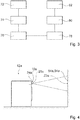
- Fig. 3 shows a schematic flowchart of some method steps of a method with the laundry processing device 10.
- the image 22 is generated by the computing unit 50 and the LCoS controller 58 and output by the projector 24.
- the image 22 strikes the mirror 48 and is deflected by the mirror 48 in the direction of the viewing window 42, in particular the projection element 44.
- the image 22 is displayed on the projection element 44 configured as a rear projection element in such a way that it is visible to an operator from outside the laundry processing device 12.
- the interaction surface 54, 54 ' ie the surface of the viewing panel 42 covered by the image 22, 22', is touched by an operator.
- step 80 when the interaction surface 54, 54 'is touched, a control command is transmitted by the computing unit 50 to a control unit (not shown) of the laundry processing device 12 and a Operating mode of laundry processing device 12 started.
- device information in particular information about the previously started operating mode, is output via the projection unit 20 as an image 22.
- the Fig. 4 shows an alternative laundry processing device 12a which comprises an alternative laundry processing device 10a.
- the laundry processing device 10a has a projection unit 20a with a projector 24a.
- the projector 24a is provided to project an image 22a onto a surface 84a arranged outside of the laundry processing device 12a.
- the one surface 84a arranged outside of the laundry processing appliance 12a forms an interaction surface 54a.
- the projector 24a is at least partially integrated in the laundry processing device 12a, but it is also conceivable that the projector 24a is or can be arranged outside the laundry processing device 12a and in particular wired or wirelessly with the laundry processing device 12a, in particular a control unit (not shown) of the laundry processing device 12a, communicated.
Landscapes
- Engineering & Computer Science (AREA)
- Textile Engineering (AREA)
- Detail Structures Of Washing Machines And Dryers (AREA)
- Main Body Construction Of Washing Machines And Laundry Dryers (AREA)
- Casings For Electric Apparatus (AREA)
- Control Of Washing Machine And Dryer (AREA)
- Physical Water Treatments (AREA)
Abstract
Description
- Die Erfindung betrifft eine Wäschebearbeitungsvorrichtung nach dem Anspruch 1, eine Projektionseinheit für die Wäschebearbeitungsvorrichtung nach dem Anspruch 15 und ein Verfahren mit der Wäschebearbeitungsvorrichtung nach Anspruch 16.
- Die Aufgabe der Erfindung besteht insbesondere darin, eine gattungsgemäße Vorrichtung mit verbesserten Eigenschaften hinsichtlich einer Flexibilität bereitzustellen. Die Aufgabe wird erfindungsgemäß durch die Merkmale der Ansprüche 1, 15 und 16 gelöst, während vorteilhafte Ausgestaltungen und Weiterbildungen der Erfindung den Unteransprüchen entnommen werden können.
- Es wird eine Wäschebearbeitungsvorrichtung mit einem Wäschebearbeitungsgerät, insbesondere einer Waschmaschine, einem Waschtrockner und/oder einem Wäschetrockner, mit zumindest einem Wasch- und/oder Trockenbehälter zur Aufnahme einer zu bearbeitenden Wäsche, mit einem Grundkörper, welcher zumindest eine Tür zu einer Begrenzung des Wasch- und/oder Trockenbehälters aufweist und mit einer Projektionseinheit, welche zumindest dazu vorgesehen ist, zumindest ein Bild, insbesondere zumindest mit Geräteinformation des Wäschebearbeitungsgeräts, mittels einer Projektion auszugeben, vorgeschlagen. Durch eine derartige Ausgestaltung kann vorteilhaft eine hohe Flexibilität erreicht werden. Insbesondere kann vorteilhaft eine beliebige Anzahl an Anzeigen und/oder Interfaces (z.B. in verschiedenen Sprachen, verschiedenen Farben, verschiedenen Anordnungen etc.) mittels der Projektionseinheit angezeigt werden. Dadurch kann vorteilhaft eine Anzahl von Displayvarianten oder Bedienblendenvarianten reduziert werden. Zudem kann vorteilhaft eine Vielzahl verschiedener Größen der Anzeige und/oder des Interfaces ermöglicht werden, insbesondere indem eine Größe der durch die Projektionseinheit ausgegebenen Projektion, beispielsweise mittels eines Objektivs o.ä., variiert werden kann. Zudem kann vorteilhaft die Anzeige und/oder das Interface an verschiedene Situationen angepasst werden, beispielsweise könnte das durch die Projektionseinheit ausgegebene Bild unterschiedliche Inhalte an einem Verkaufsort (Point of Sale) und an einem Betriebsort anzeigen. Außerdem kann die Projektionseinheit im Vergleich zu einem Display, z.B. einem TFT-Display, ein vorteilhaft niedriges Verhältnis aus Energieverbrauch und erreichbarer Displaydiagonale auf, insbesondere da ein Projektor nur eine einzelne LED als Lichtquelle benötigt. Vorteilhaft können durch eine Reduktion einer Anzahl notwendiger LEDs für eine Anzeige zudem Kosten und Energiebedarf gesenkt werden. Die Projektionseinheit ist vorzugsweise innerhalb des Wäschebearbeitungsgeräts angeordnet. Es ist jedoch auch denkbar, dass die Projektionseinheit, insbesondere ein Projektor der Projektionseinheit, zumindest teilweise außerhalb oder vollständig außerhalb des Wäschebearbeitungsgeräts angeordnet ist. Vorzugsweise ist die Projektionseinheit dazu vorgesehen, das Bild derart auszugeben, dass es auf eine Fläche, insbesondere auf eine von außen sichtbare Fläche, des Wäschebearbeitungsgeräts projiziert wird. Es ist jedoch auch denkbar, dass die Projektionseinheit dazu vorgesehen, das Bild derart auszugeben, dass es auf eine Fläche projiziert wird, welche nicht zu dem Wäschebearbeitungsgerät zugehörig ist, beispielsweise auf eine Wand, auf einen Boden oder auf eine speziell dafür vorgesehene Leinwand.
- Zudem wird vorgeschlagen, dass die Projektionseinheit zumindest den Projektor umfasst, und dass der Projektor zumindest teilweise in die Tür, insbesondere in einen Türflügel der Tür und/oder in einen mit dem Türflügel mitgeschwenkten Rahmen der Tür integriert ist. Dadurch kann vorteilhaft eine hohe Kompaktheit der Gesamtkonstruktion erreicht werden. Zudem kann vorteilhaft auf zusätzliche optische Einkoppelelemente, welche dazu vorgesehen sind, ein Bild eines Projektors von außerhalb der Tür in die Tür einzukoppeln, verzichtet werden. Dadurch kann vorteilhaft ein einfacher Aufbau erreicht werden. Vorteilhaft kann eine hohe Flexibilität, insbesondere hinsichtlich einer Wahl eines Projektors und/oder hinsichtlich eines Austauschs eines Projektors erreicht werden, insbesondere da ein Zugang zu einer Tür oder ein Austausch einer Tür weitaus einfacher ist als ein Öffnen des gesamten Geräts. Beispielsweise kann die Projektionseinheit und/oder der Projektor vorteilhaft ein eigenes Modul ausbilden, welches insbesondere einfach montierbar oder demontierbar ist. Zudem kann vorteilhaft auf ein Display in der Tür, insbesondere im Bereich einer Sichtscheibe der Tür, verzichtet werden, wodurch insbesondere Kosten gering gehalten werden können. Vorteilhaft kann eine Größe einer Projektion des Projektors stufenlos eingestellt und/oder variiert werden. Dadurch kann vorteilhaft eine hohe Flexibilität hinsichtlich einer Anzeigegröße erreicht werden. Außerdem kann, insbesondere durch einen modularen Aufbau von Tür und/oder Projektionseinheit eine einfache Nachrüstung von bereits im Einsatz befindlichen Geräten ermöglicht werden.
- Unter einer "Wäschebearbeitungsvorrichtung" soll insbesondere eine Waschmaschinenvorrichtung, eine Waschtrocknervorrichtung und/oder eine Wäschetrocknervorrichtung verstanden werden, welche zumindest ein Teil, insbesondere eine Unterbaugruppe, eines Wäschebearbeitungsgeräts, insbesondere einer Waschmaschine, eines Waschtrockners und/oder eines Wäschetrockners, ausbildet. Insbesondere kann die Wäschebearbeitungsvorrichtung auch das gesamte Wäschebearbeitungsgerät umfassen. Unter einem "Grundkörper" soll insbesondere ein Teil des Wäschebearbeitungsgeräts verstanden werden, welcher das Wäschebearbeitungsgerät nach außen begrenzt. Vorzugsweise bildet der Grundkörper ein Gehäuse, vorzugsweise inklusive Tür, des Wäschebearbeitungsgeräts aus. Unter einer "Projektionseinheit" soll insbesondere eine Einheit, vorzugsweise ein optisches Gerät, verstanden werden, welche/s dazu vorgesehen ist, eine zweidimensionale Vorlage auf einer Bildfläche, insbesondere mittels einer Projektion, abzubilden. Der Projektor weist insbesondere zumindest ein Objektiv auf. Der Projektor weist insbesondere eine eigene Lichtquelle auf. Vorteilhaft benötigt der Projektor im Vergleich zu einem Display, beispielsweise einem TFT-Display lediglich eine einzige Lichtquelle, beispielsweise LED. Dadurch kann vorteilhaft eine Anzahl von LEDs und somit auch Kosten gering gehalten werden. Vorteilhaft kann ein besonders günstiges Verhältnis aus Kosten oder Energiebedarf zu Displaygröße erreicht werden. Der Projektor ist dazu vorgesehen eine, insbesondere mittels eines Liquid Crystal on Silicon (LCoS)-Controllers erzeugte, Vorlage, vorzugsweise vergrößert, abzubilden. Das Bild ist insbesondere als ein statisches Bild oder als ein bewegtes Bild ausgebildet. Das Bild kann insbesondere zu einer Anzeige von Geräteinformationen und/oder zu einer Bereitstellung von Bedienschaltflächen dienen. Unter einer "Geräteinformation" soll insbesondere eine dem Wäschebearbeitungsgerät zugeordnete Information und/oder Eingabeaufforderung verstanden werden. Die Geräteinformation kann insbesondere eine Information über einen Status, einen Betriebszustand, einen Betriebsfortschritt, einen Betriebsmodus, eine Handlungsanweisung oder dergleichen umfassen. Beispielsweise kann eine verbleibende Dauer bis zu einer Fertigstellung des aktuellen Wäschebearbeitungsvorgangs angezeigt werden. Insbesondere ist das Bild dazu vorgesehen, jegliche Anzeige darzustellen, welche auch durch ein projektionsfreies Bedienpanel eines Wäschebearbeitungsgeräts angezeigt werden kann. Die Tür ist insbesondere dazu vorgesehen, den Wasch- und/oder Trockenbehälter wasserdicht zu verschließen. Die Tür ist insbesondere zumindest bereichs- und/oder teilweise transparent ausgebildet. Die Tür ist vorzugsweise auf einer Frontseite des, insbesondere als Frontloader ausgebildeten, Wäschebearbeitungsgeräts angeordnet. Alternativ kann die Tür aber auch beispielsweise auf einer Oberseite eines, insbesondere als Toploader ausgebildeten Wäschebearbeitungsgeräts angeordnet sein. Unter der Wendung "in die Tür integriert" soll insbesondere an und/oder vorzugsweise in der Tür angeordnet verstanden werden. Insbesondere ist der Projektor derart in die Tür, insbesondere den Türflügel, integriert, dass er bei einer Bewegung der Tür, insbesondere des Türflügels, mitbewegt wird, vorzugsweise bei einer Schwenkung der Tür, insbesondere des Türflügels, mitgeschwenkt wird. Insbesondere ist der Projektor positionsfest relativ zu einem Rahmen der Tür an der Tür befestigt. Unter "vorgesehen" soll insbesondere speziell ausgelegt und/oder ausgestattet verstanden werden. Darunter, dass ein Objekt zu einer bestimmten Funktion vorgesehen ist, soll insbesondere verstanden werden, dass das Objekt diese bestimmte Funktion in zumindest einem Anwendungs- und/oder Betriebszustand erfüllt und/oder ausführt.
- Ferner wird vorgeschlagen, dass der Projektor zwischen einem äußeren Rahmen und einem inneren Rahmen eines Türflügels der Tür angeordnet ist. Dadurch kann vorteilhaft eine besonders hohe Kompaktheit und/oder eine besonders einfache Ausgestaltung der Waschgerätevorrichtung erreicht werden. Insbesondere kann eine besonders vorteilhafte Integration des Projektors in die Tür erreicht werden. Insbesondere überlappen der äußere Rahmen und der innere Rahmen in zumindest einer Richtung, insbesondere in einer senkrecht auf eine Sichtfläche der Tür stehende Richtung, zumindest zu einem Großteil. Unter einem "Großteil" soll insbesondere 51 %, vorzugsweise 66 %, bevorzugt 75 % und besonders bevorzugt 90 % verstanden werden. Insbesondere umfasst der äußere Rahmen und/oder der innere Rahmen zumindest eine, vorzugsweise in zumindest einer Ebene vollständig von dem Rahmen umgebene, Sichtöffnung, welche dazu vorgesehen ist, eine Sichtscheibe aufzunehmen. Unter einem Türflügel soll insbesondere ein beweglicher, vorzugsweise schwenkbarer, Teil einer Tür verstanden werden. Insbesondere ist der äußere Rahmen auf einer dem Wasch- und/oder Trockenbehälter abgewandten Seite der Tür angeordnet. Insbesondere ist der innere Rahmen auf einer dem Wasch- und/oder Trockenbehälter zugewandten Seite der Tür angeordnet.
- Außerdem wird vorgeschlagen, dass die Tür ein Abstandshalterelement aufweist, welches zwischen dem äußeren Rahmen und dem inneren Rahmen angeordnet ist und welches einen Aufnahmeraum ausbildet, der zumindest dazu vorgesehen ist, den Projektor aufzunehmen. Dadurch kann eine besonders vorteilhafte Integration des Projektors in die Tür sichergestellt werden. Insbesondere kann eine besonders hohe Stabilität der Tür mit dem integrierten Projektor erreicht werden. Insbesondere ist das Abstandshalterelement, der innere Rahmen und/oder der äußere Rahmen zumindest im Wesentlichen ring- oder ellipsenförmig ausgebildet. Insbesondere ist das Abstandshalterelement dazu vorgesehen, zumindest formschlüssig mit dem inneren Rahmen und/oder mit dem äußeren Rahmen verbunden zu werden. Insbesondere bildet das Abstandshalterelement zumindest ein Versteifungselement aus, welches dazu vorgesehen ist, die Tür, insbesondere den Türflügel, vorzugsweise zumindest in einer Türebene der Tür, zu versteifen. Insbesondere berühren sich in einem montierten Zustand der Tür der äußere Rahmen und das Abstandshalterelement, der innere Rahmen und das Abstandshalterelement und/oder der innere Rahmen und der äußere Rahmen. Vorzugsweise ist der Aufnahmeraum auf einer dem inneren Rahmen zugewandten Seite des Abstandshalterelements angeordnet. Bevorzugt ist der Projektor auf einer dem inneren Rahmen zugewandten Seite des Abstandshalterelements angeordnet. Alternativ kann der Aufnahmeraum auch auf einer dem äußeren Rahmen zugewandten Seite des Abstandshalterelements angeordnet sein. Insbesondere sind Maße und/oder Form des Aufnahmeraums zumindest im Wesentlichen an eine Form des Projektors angepasst.
- Zusätzlich wird vorgeschlagen, dass der Projektor in einer unteren Hälfte der Tür angeordnet ist. Dadurch kann vorteilhaft eine besonders hohe Kompaktheit der Projektionseinheit, insbesondere in eine Richtung senkrecht zu der Sichtfläche der Tür, erreicht werden. Insbesondere kann trotz eines begrenzten Raums in der Tür ein vorteilhaft großer Projektionspfad erreicht werden, wodurch eine möglichst geringe Komplexität eines Optiksystems, insbesondere eines Spiegel- und/oder Linsensystems, der Projektionseinheit zu einer Führung des projizierten Bilds erreicht werden.
- Des Weiteren wird vorgeschlagen, dass die Projektionseinheit zumindest das Optiksystem umfasst, welches dazu vorgesehen ist, das durch den Projektor ausgegebene Bild derart umzulenken, dass es auf einer Vorderfläche des Grundkörpers erscheint. Dadurch kann eine vorteilhaft hohe Kompaktheit der Waschgerätevorrichtung erreicht werden, insbesondere mit einer besonders effektiven Raumausnutzung. Vorzugsweise umfasst das Optiksystem zumindest einen Spiegel und/oder zumindest eine Linse. Insbesondere ist das Optiksystem dazu vorgesehen, einen von dem Projektor ausgesandten Lichtstrahl zumindest einmal um zumindest 90° abzulenken. Insbesondere ist eine Projektionsrichtung des Projektors, welche insbesondere durch eine Abstrahlrichtung des Objektivs des Projektors vorgegeben ist, im Wesentlichen parallel zu einer Projektionsebene auf, welche das durch den Projektor projizierte Bild für einen Bediener sichtbar dargestellt wird. Unter "im Wesentlichen parallel" soll hier insbesondere eine Ausrichtung einer Richtung relativ zu einer Bezugsrichtung, insbesondere in einer Ebene, verstanden werden, wobei die Richtung gegenüber der Bezugsrichtung eine Abweichung insbesondere kleiner als 8°, vorteilhaft kleiner als 5° und besonders vorteilhaft kleiner als 2° aufweist. Unter einer "Vorderfläche" des Grundkörpers soll insbesondere die Sichtfläche der Tür verstanden werden. Die Sichtfläche der Tür ist insbesondere die für einen Bediener von außen sichtbare Oberfläche der Tür. Alternativ ist denkbar, dass mittels des Optiksystems das von dem Projektor ausgegebene Bild derart umgelenkt wird, dass es aus der Tür herausgeführt und auf einer außerhalb der Tür liegenden Vorderfläche des Grundkörpers erscheint, beispielsweise in einem Bereich einer Bedienblende des Wäschebearbeitungsgeräts. Insbesondere ist denkbar, dass ein Teil des durch den Projektor ausgegebenen Bilds derart von dem Optiksystem abgelenkt wird, dass es auf einer Vorderfläche der Tür erscheint und dass ein weiterer Teil des durch den Projektor ausgegebenen Bilds derart abgelenkt wird, dass es auf einer Vorderfläche des Grundkörpers in einem Bereich außerhalb der Tür, beispielsweise in einem Bereich eines Bedienpanels des Wäschebearbeitungsgeräts, erscheint. Dazu ist es insbesondere notwendig, das ausgegebene Bild in zwei Teilbilder aufzuteilen, welche jeweils unterschiedlich von dem Optiksystem ablenkbar sind.
- Weiterhin wird vorgeschlagen, dass das Optiksystem dazu vorgesehen ist, das durch den Projektor ausgegebene Bild derart umzulenken, dass es in der Sichtscheibe der Tür erscheint. Dadurch kann vorteilhaft eine hohe Flexibilität erreicht werden. Insbesondere kann vorteilhaft eine bereits vorhandene, vorteilhaft in einem Sichtfeld eines Bedieners liegende, Fläche zusätzlich für eine Bildanzeige verwendet werden. Die Sichtscheibe ist insbesondere als eine zumindest im Wesentlichen transparente Scheibe ausgebildet, welche dazu vorgesehen ist, eine Sicht in den Wasch- und/oder Trockenbehälter, insbesondere auch während eines aktiven Betriebs des Wäschebearbeitungsgeräts, zu erlauben. Die Sichtscheibe ist im Wesentlichen zentral in der Tür angeordnet. Insbesondere ist die Sichtscheibe zumindest im Wesentlichen rund oder elliptisch. Insbesondere ist ein Zentrum der Sichtscheibe relativ zu einem Zentrum des Türflügels leicht nach oben versetzt angeordnet. Dadurch kann vorteilhaft zusätzlicher Bauraum für die Integration des Projektors geschaffen werden.
- Wenn das Optiksystem zumindest ein Projektionselement umfasst, welches auf die Sichtscheibe aufgebracht ist und welches dazu vorgesehen ist, das durch den Projektor ausgegebene Bild darzustellen, kann vorteilhaft eine besonders hohe Lichtausbeute einer Projektion erreicht werden, wodurch vorteilhaft ein Energiebedarf möglichst niedrig gehalten werden kann. Das Projektionselement ist insbesondere dazu vorgesehen, das durch den Projektor ausgegebene Bild zumindest teilweise zu absorbieren. Vorzugsweise ist das Projektionselement mit der Sichtscheibe verklebt oder verschweißt.
- Zudem wird vorgeschlagen, dass das Projektionselement als ein/e, insbesondere zumindest teilweise transparente/s, Rückprojektionselement, insbesondere Rückprojektionsfolie, ausgebildet ist. Dadurch kann vorteilhaft das Optiksystem besonders einfach ausgestaltet werden, insbesondere da eine Einstrahlung des Bilds von einer Rückseite einer Sichtfläche erfolgen kann. Unter "teilweise transparent" soll insbesondere mit einer mittleren Transmissivität über alle sichtbaren Lichtwellenlängen von zumindest 30 %, vorzugsweise zumindest 50 %, bevorzugt von zumindest 70 % und besonders bevorzugt von höchstens 90 %, verstanden werden. Insbesondere ist das Rückprojektionselement dazu vorgesehen, ein von einer Rückseite des Rückprojektionselements aus eingestrahltes Bild auf einer Vorderseite des Rückprojektionselements für einen Betrachter sichtbar zu machen. Insbesondere weist das Rückprojektionselement einen Leuchtdichtefaktor (bei einem Blickwinkel von 0°) von zumindest 1,05, vorzugsweise von zumindest 1,3, bevorzugt von zumindest 1,5 und besonders bevorzugt von zumindest 2 auf. Insbesondere ist das Rückprojektionselement als eine Rückprojektionsfolie aus PVC ausgebildet.
- Wenn das Optiksystem dazu vorgesehen ist, das durch den Projektor ausgegebene Bild derart umzulenken, dass es auf einer Vorderfläche einer Rahmeneinheit einer Sichtscheibe der Tür, insbesondere des Türflügels, erscheint, kann vorteilhaft eine hohe Flexibilität erreicht werden. Insbesondere kann vorteilhaft eine bereits vorhandene, vorteilhaft in einem Sichtfeld eines Bedieners liegende, Fläche zusätzlich für eine Bildanzeige verwendet werden. Vorteilhaft bleibt zudem ein ungehinderter Blick in ein Inneres des Wasch- und/oder Trockenbehälters durch die Sichtscheibe möglich.
- Außerdem wird vorgeschlagen, dass das Optiksystem zumindest den Spiegel umfasst, welcher insbesondere zumindest dazu vorgesehen ist, das durch den Projektor ausgegebene Bild um einen Winkel von wenigstens 50°, vorzugsweise von wenigstens 60° und bevorzugt von wenigstens 80° abzulenken. Der Spiegel ist insbesondere als ein vollreflektierender oder als ein semitransparenter Spiegel ausgebildet. Durch einen semitransparenten Spiegel kann vorteilhaft ein Blick in das Innere des Wasch- und/oder Trockenbehälters durch die Sichtscheibe und durch den semitransparenten Spiegel ermöglicht werden. Insbesondere weist der semitransparente Spiegel eine Transmission von mindestens 30 %, vorzugsweise mindestens 50 % und bevorzugt mindestens 65 % auf. Insbesondere ist denkbar, dass der Spiegel als ein elektrisch schaltbarer Spiegel ausgebildet ist, dessen Transparenz und/oder Reflektivität von einer angelegten Spannung abhängt.
- Des Weiteren wird vorgeschlagen, dass die Projektionseinheit eine Recheneinheit aufweist, welche zumindest zu einer Ansteuerung des Projektors vorgesehen ist und welche in die Tür integriert ist. Dadurch kann vorteilhaft ein einfacher Aufbau erreicht werden. Beispielsweise kann die Recheneinheit vorteilhaft ein eigenes Modul ausbilden, welches insbesondere einfach montierbar oder demontierbar ist. Vorteilhaft kann die Recheneinheit ein Speichermodul umfassen, welches dazu vorgesehen ist, verschiedene Programme abzuspeichern, die insbesondere dazu vorgesehen sind, Informationen in verschiedenen Sprachen oder in verschiedenen Designs zur Projektion mittels des Projektors auszugeben. Auch ist dadurch beispielsweise möglich, unterschiedliche Anzeigen für unterschiedliche Aufgaben auszugeben. Beispielsweise könnte an einem Verkaufsort eine Übersicht der Gerätespezifikationen oder ein Verkaufspreis durch die Projektionseinheit angezeigt werden. Unter einer "Recheneinheit" soll insbesondere eine Einheit mit einem Informationseingang, einer Informationsverarbeitung und einer Informationsausgabe verstanden werden. Vorteilhaft weist die Recheneinheit zumindest einen Prozessor, einen Speicher, Ein- und Ausgabemittel, weitere elektrische Bauteile, ein Betriebsprogramm, Regelroutinen, Steuerroutinen und/oder Berechnungsroutinen auf. Vorzugsweise sind die Bauteile der Recheneinheit auf einer gemeinsamen Platine angeordnet und/oder vorteilhaft in einem gemeinsamen Gehäuse angeordnet. Insbesondere ist die Recheneinheit als ein Einplatinencomputer, beispielsweise ein Raspberry Pi®-Computer, ausgebildet. Insbesondere umfasst die Recheneinheit den LCoS-Controller oder ist mit einem von der Recheneinheit getrennt ausgebildeten LCoS-Controller der Projektionseinheit verbunden. Insbesondere umfasst die Projektionseinheit eine Kühleinheit, welche zumindest dazu vorgesehen ist, die Recheneinheit, den Projektor und/oder den LCoS-Controller zu kühlen. Vorzugsweise ist die Kühleinheit als ein Ventilator oder als ein kaskadiertes Peltier-Element ausgebildet. Unter einer "Ansteuerung des Projektors" soll insbesondere ein Erzeugen und Übertragen eines Bildes an den Projektor, insbesondere mit Hilfe des LCoS-Controllers, verstanden werden. Insbesondere ist die Recheneinheit derart in die Tür, insbesondere den Türflügel, integriert, dass sie bei einer Bewegung der Tür, insbesondere des Türflügels, mitbewegt wird, vorzugsweise bei einer Schwenkung der Tür, insbesondere des Türflügels, mitgeschwenkt wird. Insbesondere ist der Projektor positionsfest relativ zu einem Rahmen der Tür an der Tür befestigt. Insbesondere ist die Recheneinheit zwischen dem äußeren Rahmen und dem inneren Rahmen des Türflügels angeordnet. Insbesondere ist die Recheneinheit in dem Aufnahmeraum angeordnet.
- Ferner wird vorgeschlagen, dass die Projektionseinheit, insbesondere die Recheneinheit, eine drahtlose Kommunikationsschnittstelle umfasst. Dadurch kann vorteilhaft eine Flexibilität weiter erhöht werden. Insbesondere kann vorteilhaft eine Vielzahl an Bildern, Informationen und/oder Daten an die Projektionseinheit übermittelt werden, welche anschließend von dem Projektor in einem Bild ausgegeben werden können. Vorteilhaft erlaubt die Kommunikationsschnittstelle ein Update, eine Neuinstallation und/oder einen Austausch des Betriebsprogramms, der Regelroutinen, der Steuerroutinen und/oder der Berechnungsroutinen der Recheneinheit. Zudem ist denkbar, dass Daten über die Kommunikationsschnittstelle auf die Recheneinheit gestreamt und durch den Projektor angezeigt werden können. Insbesondere ist die Kommunikationsschnittstelle dazu vorgesehen, von der Recheneinheit erhaltene Daten auszusenden und/oder Daten zu empfangen und an die Recheneinheit zu übermitteln. Vorzugsweise umfasst die Kommunikationsschnittstelle eine WLAN-Schnittstelle, eine Bluetooth-Schnittstelle, eine ZigBee-Schnittstelle, eine NFC-Schnittstelle, eine WiMax-Schnittstelle, eine Enocean-Schnittstelle, eine Z-Wave-Schnittstelle oder dergleichen. Alternativ oder zusätzlich ist denkbar, dass die Recheneinheit eine kabelbasierte Schnittstelle, wie z.B. USB oder LAN, umfasst.
- Außerdem wird vorgeschlagen, dass eine Fläche, über welche sich das durch den Projektor ausgegebene Bild erstreckt, eine Interaktionsfläche für einen Bediener ausbildet, welche insbesondere dazu vorgesehen ist, auf eine Annäherung oder eine Berührung einer Bedienerhand zu reagieren. Dadurch kann vorteilhaft eine hohe Flexibilität erreicht werden, insbesondere da Möglichkeiten für eine Benutzerinteraktion mit dem durch den Projektor dargestellten Bild frei sind von Einschränkungen durch vordefinierte Schaltknöpfe. Vorteilhaft kann zudem eine besonders hohe Bedienerfreundlichkeit und Intuitivität erreicht werden. Vorteilhaft bildet die Fläche, über welche sich das durch den Projektor ausgegebene Bild erstreckt, einen Touchscreen oder einen Touchless-Touchscreen aus. Insbesondere erstreckt sich die Interaktionsfläche zumindest über einen Großteil des Projektionselements oder über das gesamte Projektionselement. Insbesondere umfasst die Interaktionsfläche einen Teil einer Oberfläche des Wäschebearbeitungsgeräts. Alternativ ist jedoch auch denkbar, dass die Interaktionsfläche auf einer Oberfläche angeordnet ist, welche getrennt von dem Wäschebearbeitungsgerät ist, d.h. insbesondere keinen Teil der Oberfläche des Wäschebearbeitungsgeräts ausbildet. Beispielsweise kann die Interaktionsfläche auf einer Wand oder auf einem Boden eines Raums in dem das Wäschebearbeitungsgerät aufgestellt ist, angeordnet sein.
- Des Weiteren wird vorgeschlagen, dass die Projektionseinheit ein optisches Erfassungselement aufweist, welches dazu vorgesehen ist, die Annäherung der Bedienerhand an die Interaktionsfläche und/oder die Berührung der Interaktionsfläche durch die Bedienerhand zu sensieren. Dadurch kann vorteilhaft eine hohe Flexibilität erreicht werden, insbesondere indem eine Vielzahl möglicher Anordnungen der Interaktionsfläche, insbesondere innerhalb des Wäschebearbeitungsgeräts oder außerhalb des Wäschebearbeitungsgeräts ermöglicht werden kann. Insbesondere ist die Interaktionsfläche frei von einer Touch-Folie ausgebildet. Dadurch kann vorteilhaft eine besonders einfache Konstruktion ermöglicht werden, wodurch insbesondere Kosten niedrig gehalten werden können. Zudem kann vorteilhaft eine Größe der Interaktionsfläche beliebig eingestellt und/oder geändert werden. Insbesondere ist das optische Erfassungselement als eine Fotodiode, vorzugsweise eine Infrarot-Diode, ausgebildet, welche dazu vorgesehen ist, eine Annäherung an die Interaktionsfläche oder eine Berührung der Interaktionsfläche zu detektieren. Insbesondere ist die Fotodiode dazu vorgesehen, einen Infrarot-Touchscreen auszubilden. Vorteilhaft kann dadurch eine hohe Präzision und Geschwindigkeit von Interaktionen mittels der Interaktionsfläche gewährleistet werden.
- Ferner wird ein Verfahren mit der Wäschebearbeitungsvorrichtung vorgeschlagen, bei welchem insbesondere ein Bild auf eine Sichtscheibe eines Wäschebearbeitungsgeräts projiziert wird und mittels welchem vorteilhaft eine hohe Flexibilität erreicht werden kann.
- Die Wäschebearbeitungsvorrichtung soll hierbei nicht auf die oben beschriebene Anwendung und Ausführungsform beschränkt sein. Insbesondere kann die Wäschebearbeitungsvorrichtung zu einer Erfüllung einer hierin beschriebenen Funktionsweise eine von einer hierin genannten Anzahl von einzelnen Elementen, Bauteilen und Einheiten abweichende Anzahl aufweisen.
- Weitere Vorteile ergeben sich aus der folgenden Zeichnungsbeschreibung. In der Zeichnung sind Ausführungsbeispiele der Erfindung dargestellt. Die Zeichnung, die Beschreibung und die Ansprüche enthalten zahlreiche Merkmale in Kombination. Der Fachmann wird die Merkmale zweckmäßigerweise auch einzeln betrachten und zu sinnvollen weiteren Kombinationen zusammenfassen.
- Es zeigen:
- Fig. 1
- eine schematische Frontalansicht eines Wäschebearbeitungsgeräts mit einer Wäschebearbeitungsvorrichtung,
- Fig. 2
- eine schematische Explosionsdarstellung eines Teils der Wäschebearbeitungsvorrichtung,
- Fig. 3
- ein schematisches Ablaufdiagramm eines Verfahrens mit der Wäschebearbeitungsvorrichtung und
- Fig. 4
- eine schematische Seitenansicht eines alternativen Wäschebearbeitungsgeräts mit einer alternativen Wäschebearbeitungsvorrichtung.
-
Figur 1 zeigt eine Frontalansicht eines als Frontloader ausgebildeten Wäschebearbeitungsgeräts 12. Das beispielhaft dargestellte Wäschebearbeitungsgerät 12 aus derFig. 1 ist ein Waschtrockner. Alternativ könnte das Wäschebearbeitungsgerät 12 jedoch genauso ein Wäschetrockner oder ein Waschvollautomat sein. Das Wäschebearbeitungsgerät 12 weist eine Wäschebearbeitungsvorrichtung 10 auf. Die Wäschebearbeitungsvorrichtung 10 weist einen Wasch- und/oder Trockenbehälter 14 auf. Der Wasch- und/oder Trockenbehälter 14 ist zu einer Aufnahme einer zu bearbeitenden Wäsche vorgesehen. Der Wasch- und/oder Trockenbehälter 14 bildet eine Wasch- und/oder Trockentrommel aus. Die Wäschebearbeitungsvorrichtung 10 weist einen Grundkörper 16 auf. Der Grundkörper 16 umfasst zumindest ein Teil eines Gehäuses 56 des Wäschebearbeitungsgeräts 12. Der Grundkörper 16 bildet das Gehäuse 56 des Wäschebearbeitungsgeräts 12 aus. Der Grundkörper 16 weist eine Tür 18 auf. Die Tür 18 ist zu einer Begrenzung des Wasch- und/oder Trockenbehälters 14 nach außen vorgesehen. Die Tür 18 ist zu einem zumindest wasserdichten Verschließen des Wasch- und/oder Trockenbehälters 14 bei einem Wasch- und/oder Trockenvorgang vorgesehen. Die Tür 18 umfasst einen Türflügel 30. Der Türflügel 30 ist um eine Vertikalachse schwenkbar ausgebildet. - Die Wäschebearbeitungsvorrichtung 10 weist eine Projektionseinheit 20 auf. Die Projektionseinheit 20 ist dazu vorgesehen, ein Bild 22 mittels einer Projektion auszugeben. Das Bild 22 kann, wie beispielhaft in
Fig. 1 dargestellt, ein Bedienpanel und/oder eine Geräteinformation des Wäschebearbeitungsgeräts 12 anzeigen (hier: eine verbleibende Restzeit eines Betriebsvorgangs). Die Projektionseinheit 20 ist in die Tür 18 integriert. In derFig. 1 ist ein Bild 22 beispielhaft auf eine Sichtscheibe 42 des Wäschebearbeitungsgeräts 12 projiziert dargestellt. In derFig. 1 ist ein weiteres Bild 22' beispielhaft in einen Bereich einer oberen Bedienblende 60 des Wäschebearbeitungsgeräts 12 projiziert dargestellt. Alternativ ist selbstverständlich auch denkbar, dass das Bild 22, 22' nur in den Bereich der Bedienblende 60 oder nur in den Bereich der Sichtscheibe 42 projiziert wird. -
Fig. 2 zeigt eine Explosionsdarstellung eines Teils der Wäschebearbeitungsvorrichtung 10, insbesondere des Türflügels 30 der Tür 18 des Wäschebearbeitungsgeräts 12. Die Wäschebearbeitungsvorrichtung 10 weist eine Rahmeneinheit 46 auf. Der Türflügel 30 weist die Rahmeneinheit 46 auf. Die Rahmeneinheit 46 umfasst einen äußeren Rahmen 26. Der äußere Rahmen 26 ist auf einer dem Wasch- und/oder Trockenbehälter 14 abgewandten Seite der Tür 18 angeordnet. Der äußere Rahmen 26 ist ringförmig ausgebildet. Die Rahmeneinheit 46 umfasst einen inneren Rahmen 28. Der innere Rahmen 28 ist auf einer dem Wasch- und/oder Trockenbehälter 14 zugewandten Seite der Tür 18 angeordnet. Der innere Rahmen 28 ist ringförmig ausgebildet. Der innere Rahmen 28 ist in einer unteren Hälfte 36 der Tür 18 breiter als in einer oberen Hälfte 68 der Tür 18. Dadurch kann vorteilhaft ein ausreichender Bauraum für die Projektionseinheit 20 bereitgestellt werden. Die Tür 18, insbesondere der Türflügel 30, weist die Sichtscheibe 42 auf. Die Sichtscheibe 42 ist als ein äußeres Scheibenelement der Tür 18 ausgebildet. Die Sichtscheibe 42 begrenzt in einem geschlossenen Zustand der Tür 18 das Wäschebearbeitungsgerät 12 nach außen. Die Sichtscheibe 42 ist durch den äußeren Rahmen 26 gehaltert. Die Tür 18, insbesondere der Türflügel 30, umfasst eine weitere Sichtscheibe 62. Die weitere Sichtscheibe 62 ist als ein inneres Scheibenelement der Tür 18 ausgebildet. Die innere Sichtscheibe 62 begrenzt in dem geschlossenen Zustand der Tür 18 den Wasch- und/oder Trockenbehälter 14. Die innere Sichtscheibe 62 ist durch den inneren Rahmen 28 gehaltert. - Die Projektionseinheit 20 weist einen Projektor 24 auf. Der Projektor 24 ist in die Tür 18 integriert. Der Projektor 24 ist in den Türflügel 30 integriert. Der Projektor 24 ist dazu vorgesehen, das Bild 22 in Form von Lichtstrahlen abzustrahlen. Die Projektionseinheit 20 weist eine Recheneinheit 50 auf. Die Recheneinheit 50 ist in die Tür 18 integriert. Die Recheneinheit 50 ist in den Türflügel 30 integriert. Die Recheneinheit 50 ist zu einer Ansteuerung des Projektors 24 vorgesehen. Die Recheneinheit 50 ist dazu vorgesehen, das Bild 22, welches von dem Projektor 24 abgestrahlt werden soll, zu berechnen. Die Projektionseinheit 20 weist einen LCoS-Controller 58 auf. Der LCoS-Controller 58 ist in die Tür 18 integriert. Der LCoS-Controller 58 ist in den Türflügel 30 integriert. Der LCoS-Controller 58 ist dazu vorgesehen, den Projektor 24 anzusteuern. Der LCoS-Controller 58 ist dazu vorgesehen, ein durch die Recheneinheit 50 berechnetes Bild 22 derart darzustellen, dass es der Projektor 24 durch ein Bestrahlen des LCoS-Controllers 58 ausgeben kann. Die Projektionseinheit 20 weist eine Kühleinheit 64 auf. Die Kühleinheit 64 ist in die Tür 18 integriert. Die Kühleinheit 64 ist in den Türflügel 30 integriert. Die Kühleinheit 64 ist dazu vorgesehen, zumindest eine weitere Komponente der Projektionseinheit 20, z.B. die Recheneinheit 50, den Projektor 24 und/oder den LCoS-Controller 58 zu kühlen. Die Projektionseinheit 20 weist eine drahtlose Kommunikationsschnittstelle 52 auf. Die drahtlose Kommunikationsschnittstelle 52 ist dazu vorgesehen, drahtlos mit einem externen Gerät, insbesondere mit dem Internet, zu kommunizieren. Die drahtlose Kommunikationsschnittstelle 52 ist einstückig mit der Recheneinheit 50 ausgebildet. Die drahtlose Kommunikationsschnittstelle 52 umfasst zumindest ein Sendermodul zu einem Versenden digitaler Daten. Die drahtlose Kommunikationsschnittstelle 52 umfasst zumindest ein Empfängermodul zu einem Empfangen digitaler Daten. Darunter, dass zwei Einheiten "einstückig" ausgebildet sind, soll insbesondere verstanden werden, dass die Einheiten zumindest ein, insbesondere zumindest zwei, vorteilhaft zumindest drei gemeinsame Elemente aufweisen, die Bestandteil, insbesondere funktionell wichtiger Bestandteil, beider Einheiten sind.
- Die Projektionseinheit 20 weist eine Halteeinheit 66 auf. Die Halteeinheit 66 ist dazu vorgesehen, den Projektor 24, die Recheneinheit 50, die Kühleinheit 64 und/oder den LCoS-Controller 58 an der Tür 18, insbesondere an dem Türflügel 30, zu haltern und/oder zu befestigen. Die Halteeinheit 66 ist zerstörungsfrei lösbar an die Tür 18, insbesondere an dem Türflügel 30, befestigbar. Der Projektor 24 ist zerstörungsfrei lösbar an die Halteeinheit 66 befestigbar. Die Recheneinheit 50 ist zerstörungsfrei lösbar an die Halteeinheit 66 befestigbar. Die Kühleinheit 64 ist zerstörungsfrei lösbar an die Halteeinheit 66 befestigbar. Der LCoS-Controller 58 ist zerstörungsfrei lösbar an die Halteeinheit 66 befestigbar.
- Die Projektionseinheit 20 ist zu einem Großteil zwischen dem äußeren Rahmen 26 und dem inneren Rahmen 28 des Türflügels 30 der Tür 18 angeordnet. Der Projektor 24, die Halteeinheit 66, die Kühleinheit 64, der LCoS-Controller 58 und/oder die Recheneinheit 50 ist/sind zwischen dem äußeren Rahmen 26 und dem inneren Rahmen 28 des Türflügels 30 der Tür 18 angeordnet. Die Projektionseinheit 20 ist zu einem Großteil in der unteren Hälfte 36 der Tür 18 angeordnet. Der Projektor 24, die Halteeinheit 66, die Kühleinheit 64, der LCoS-Controller 58 und/oder die Recheneinheit 50 ist/sind in der unteren Hälfte 36 der Tür 18 angeordnet.
- Die Tür 18 weist ein Abstandshalterelement 32 auf. Das Abstandshalterelement 32 ist zwischen dem äußeren Rahmen 26 und dem inneren Rahmen 28 des Türflügels 30 der Tür 18 angeordnet. Das Abstandshalterelement 32 ist ringförmig ausgebildet. Das Abstandshalterelement 32 bildet einen Aufnahmeraum 34 aus. Der durch das Abstandshalterelement 32 gebildete Aufnahmeraum 34 ist dazu vorgesehen, den Projektor 24 aufzunehmen. Der Aufnahmeraum 34 ist dazu vorgesehen, zumindest eine weitere Komponente oder mehrere weitere Komponenten der Projektionseinheit 20, z.B. die Recheneinheit 50, die Kühleinheit 64, die Halteeinheit 66 und/oder den LCoS-Controller 58, aufzunehmen. Das Abstandshalterelement 34 ist zudem dazu vorgesehen, die Tür 18, insbesondere die Rahmeneinheit 46, zu verstärken.
- Die Projektionseinheit 20 umfasst ein Optiksystem 38. Das Optiksystem 38 ist dazu vorgesehen, das durch den Projektor 24 ausgegebene Bild 22 derart umzulenken, dass es auf einer Vorderfläche 40 des Grundkörpers 16 erscheint. Alternativ oder zusätzlich kann das Optiksystem 38 dazu vorgesehen sein, das durch den Projektor 24 ausgegebene Bild 22 derart umzulenken, dass es auf einer Vorderfläche der Rahmeneinheit 46 der Sichtscheibe 42 der Tür 18 erscheint oder auf der Bedienblende 60 erscheint. Bevorzugt ist das Optiksystem 38 jedoch zumindest dazu vorgesehen, das durch den Projektor 24 ausgegebene Bild 22 derart umzulenken, dass es in der Sichtscheibe 42 der Tür 18 erscheint. Das Optiksystem 38 weist ein Projektionselement 44 auf. Das Projektionselement 44 ist dazu vorgesehen, das durch den Projektor 24 ausgegebene Bild 22 darzustellen. Das Projektionselement 44 ist auf die Sichtscheibe 42 aufgebracht. Das Projektionselement 44 ist auf die Sichtscheibe 42 aufgeschweißt. Alternativ ist denkbar, dass das Projektionselement 44 in die Sichtscheibe 42 integriert, beispielsweise zwischen Einzelscheiben der Sichtscheibe 42 angeordnet, ist oder, dass das Projektionselement 44 einstückig oder einteilig mit der Sichtscheibe 42 ausgebildet ist. Zudem ist denkbar, dass das Projektionselement 44 getrennt von der Sichtscheibe 42 ausgebildet ist. Das Projektionselement 44 ist als ein Rückprojektionselement ausgebildet. Das Rückprojektionselement ist als eine Rückprojektionsfolie ausgebildet. Das Rückprojektionselement ist teilweise transparent. Unter "einstückig" soll insbesondere stoffschlüssig verbunden, wie beispielsweise durch einen Schweißprozess und/oder Klebeprozess usw., und besonders vorteilhaft angeformt verstanden werden, wie durch die Herstellung aus einem Guss und/oder durch die Herstellung in einem Ein- oder Mehrkomponentenspritzverfahren. Das Optiksystem 38 umfasst zumindest einen Spiegel 48. Der Spiegel 48 ist dazu vorgesehen, das durch den Projektor 24 ausgegebene Bild 22 derart abzulenken, dass es auf der Vorderfläche 40 der Wäschebearbeitungsvorrichtung 10, insbesondere auf der Sichtscheibe 42 erscheint. Der Spiegel 48 ist zwischen der Sichtscheibe 42 und der weiteren Sichtscheibe 62 angeordnet. Der Spiegel 48 ist in einem Inneren des Türflügels 30 angeordnet. Das Optiksystem 38 weist eine Spiegelhalterung 70 auf. Die Spiegelhalterung 70 ist dazu vorgesehen, den Spiegel 48 relativ zu dem Projektor 24 auszurichten. Die Spiegelhalterung 70 ist dazu vorgesehen, den Spiegel 48 zu der Sichtscheibe 42 und/oder zu der weiteren Sichtscheibe 62 angewinkelt zu haltern. Es ist denkbar, dass ein Winkel des Spiegels 48 relativ zu der Sichtscheibe 42 mittels der Spiegelhalterung 70 manuell und/oder automatisiert veränderbar und/oder einstellbar ist.
- Das durch den Projektor 24 ausgegebene Bild 22 erstreckt sich über eine Fläche der Sichtscheibe 42, insbesondere über das Projektionselement 44. Die Fläche, über die sich das durch den Projektor 24 ausgegebene Bild 22 erstreckt, bildet eine Interaktionsfläche 54, 54' für einen Bediener aus. Die Interaktionsfläche 54, 54' ist dazu vorgesehen, auf eine Annäherung oder eine Berührung einer Bedienerhand zu reagieren. Die Projektionseinheit 20 weist ein optisches Erfassungselement (nicht gezeigt) auf. Das optische Erfassungselement ist in den Projektor 24 integriert. Das optische Erfassungselement ist einstückig mit dem Projektor ausgebildet. Das optische Erfassungselement ist dazu vorgesehen, die Annäherung der Bedienerhand an die Interaktionsfläche 54, 54' und/oder die Berührung der Interaktionsfläche 54, 54' durch die Bedienerhand zu sensieren. Die Interaktionsfläche 54, 54' ist frei von einer Touch-Folie ausgebildet. Das optische Erfassungselement ist als eine Fotodiode (nicht gezeigt) ausgebildet. Die Fotodiode ist als eine Infrarot-Fotodiode ausgebildet. Die Fotodiode ist dazu vorgesehen, die Annäherung oder die Berührung der Interaktionsfläche 54, 54' durch die Bedienerhand zu erkennen. Insbesondere ist die Fotodiode dazu vorgesehen, einen Annäherungs- und/oder Berührungsort innerhalb der Interaktionsfläche 54, 54' zu erkennen. Insbesondere ist die Fotodiode mit der Recheneinheit 50 derart verbunden, dass erkannte Annäherungen, Berührungen oder Gesten an die Recheneinheit 50 übermittelt werden und dort zu einer Eingabe von Steuerbefehlen dienen können.
-
Fig. 3 zeigt ein schematisches Ablaufdiagramm einiger Verfahrensschritte eines Verfahrens mit der Wäschebearbeitungsvorrichtung 10. In zumindest einem Verfahrensschritt 72 wird das Bild 22 von der Recheneinheit 50 und dem LCoS-Controller 58 erzeugt und von dem Projektor 24 ausgegeben. In zumindest einem weiteren Verfahrensschritt 74 trifft das Bild 22 auf den Spiegel 48 auf und wird von dem Spiegel 48 in Richtung der Sichtscheibe 42, insbesondere des Projektionselements 44, abgelenkt. In zumindest einem weiteren Verfahrensschritt 76 wird das Bild 22 auf dem als Rückprojektionselement ausgebildeten Projektionselement 44 so dargestellt, dass es für einen Bediener von außerhalb des Wäschebearbeitungsgeräts 12 sichtbar ist. In zumindest einem weiteren Verfahrensschritt 78 wird die Interaktionsfläche 54, 54', d.h. die von dem Bild 22, 22' bedeckte Fläche der Sichtscheibe 42, durch einen Bediener berührt. In zumindest einem weiteren Verfahrensschritt 80 wird durch die Berührung der Interaktionsfläche 54, 54' ein Steuerbefehl durch die Recheneinheit 50 an eine Steuereinheit (nicht gezeigt) des Wäschebearbeitungsgeräts 12 übermittelt und ein Betriebsmodus des Wäschebearbeitungsgeräts 12 gestartet. In zumindest einem weiteren Verfahrensschritt 82 wird eine Geräteinformation, insbesondere eine Information über den zuvor gestarteten Betriebsmodus über die Projektionseinheit 20 als Bild 22 ausgegeben. - In der
Figur 4 ist ein weiteres Ausführungsbeispiel der Erfindung gezeigt. Die nachfolgenden Beschreibungen beschränken sich im Wesentlichen auf die Unterschiede zwischen den Ausführungsbeispielen, wobei bezüglich gleichbleibender Bauteile, Merkmale und Funktionen auf die Beschreibung des Ausführungsbeispiels derFiguren 1 bis 3 verwiesen werden kann. Zur Unterscheidung der Ausführungsbeispiele ist in den Bezugszeichen des Ausführungsbeispiels in derFigur 4 der zusätzliche Buchstabe a nachgestellt. Bezüglich gleich bezeichneter Bauteile, insbesondere in Bezug auf Bauteile mit gleichen Bezugszeichen, kann grundsätzlich auch auf die Zeichnungen und/oder die Beschreibung des Ausführungsbeispiels derFiguren 1 bis 3 verwiesen werden. - Die
Fig. 4 zeigt ein alternatives Wäschebearbeitungsgerät 12a, welches eine alternative Wäschebearbeitungsvorrichtung 10a umfasst. Die Wäschebearbeitungsvorrichtung 10a weist eine Projektionseinheit 20a mit einem Projektor 24a auf. Der Projektor 24a ist dazu vorgesehen, ein Bild 22a auf eine außerhalb des Wäschebearbeitungsgeräts 12a angeordnete Fläche 84a zu projizieren. Die eine außerhalb des Wäschebearbeitungsgeräts 12a angeordnete Fläche 84a bildet dabei eine Interaktionsfläche 54a aus. In dem inFig. 4 dargestellten Beispiel ist der Projektor 24a zumindest teilweise in dem Wäschebearbeitungsgerät 12a integriert, es ist jedoch auch denkbar, dass der Projektor 24a außerhalb des Wäschebearbeitungsgeräts 12a angeordnet ist oder anordenbar ist und insbesondere kabelgebunden oder kabellos mit dem Wäschebearbeitungsgerät 12a, insbesondere einer Steuereinheit (nicht gezeigt) des Wäschebearbeitungsgeräts 12a, kommuniziert. -
- 10
- Wäschebearbeitungsvorrichtung
- 12
- Wäschebearbeitungsgerät
- 14
- Wasch- und/oder Trockenbehälter
- 16
- Grundkörper
- 18
- Tür
- 20
- Projektionseinheit
- 22
- Bild
- 24
- Projektor
- 26
- Äußerer Rahmen
- 28
- Innerer Rahmen
- 30
- Türflügel
- 32
- Abstandshalterelement
- 34
- Aufnahmeraum
- 36
- Untere Hälfte
- 38
- Optiksystem
- 40
- Vorderfläche
- 42
- Sichtscheibe
- 44
- Projektionselement
- 46
- Rahmeneinheit
- 48
- Spiegel
- 50
- Recheneinheit
- 52
- Kommunikationsschnittstelle
- 54
- Interaktionsfläche
- 56
- Gehäuse
- 58
- LCoS-Controller
- 60
- Bedienblende
- 62
- Weitere Sichtscheibe
- 64
- Kühleinheit
- 66
- Halteeinheit
- 68
- Obere Hälfte
- 70
- Spiegelhalterung
- 72
- Verfahrensschritt
- 74
- Verfahrensschritt
- 76
- Verfahrensschritt
- 78
- Verfahrensschritt
- 80
- Verfahrensschritt
- 82
- Verfahrensschritt
- 84
- Fläche
Claims (16)
- Wäschebearbeitungsvorrichtung (10, 10a) mit einem Wäschebearbeitungsgerät (12, 12a), insbesondere einer Waschmaschine, einem Waschtrockner und/oder einem Wäschetrockner, mit zumindest einem Wasch- und/oder Trockenbehälter (14) zur Aufnahme einer zu bearbeitenden Wäsche, mit einem Grundkörper (16), welcher zumindest eine Tür (18) zu einer Begrenzung des Wasch- und/oder Trockenbehälters (14) aufweist und mit einer Projektionseinheit (20, 20a), welche zumindest dazu vorgesehen ist, zumindest ein Bild (22, 22', 22a), insbesondere zumindest mit Geräteinformation des Wäschebearbeitungsgeräts (12, 12a), mittels einer Projektion auszugeben.
- Wäschebearbeitungsvorrichtung (10, 10a) nach Anspruch 1, dadurch gekennzeichnet, dass die Projektionseinheit (20, 20a) zumindest einen Projektor (24, 24a) umfasst, welcher zumindest teilweise in die Tür (18) integriert ist.
- Wäschebearbeitungsvorrichtung (10, 10a) nach Anspruch 1 oder 2, dadurch gekennzeichnet, dass der Projektor (24, 24a) zwischen einem äußeren Rahmen (26) und einem inneren Rahmen (28) eines Türflügels (30) der Tür (18) angeordnet ist.
- Wäschebearbeitungsvorrichtung (10, 10a) nach Anspruch 3, dadurch gekennzeichnet, dass die Tür (18) ein Abstandshalterelement (32) aufweist, welches zwischen dem äußeren Rahmen (26) und dem inneren Rahmen (28) angeordnet ist und welches einen Aufnahmeraum (34) ausbildet, der zumindest dazu vorgesehen ist, den Projektor (24, 24a) aufzunehmen.
- Wäschebearbeitungsvorrichtung (10, 10a) nach einem der Ansprüche 2 bis 4, dadurch gekennzeichnet, dass der Projektor (24, 24a) in einer unteren Hälfte (36) der Tür (18) angeordnet ist.
- Wäschebearbeitungsvorrichtung (10) einem der vorhergehenden Ansprüche, dadurch gekennzeichnet, dass die Projektionseinheit (20) zumindest ein Optiksystem (38) umfasst, welches dazu vorgesehen ist, das durch den Projektor (24) ausgegebene Bild (22, 22') derart umzulenken, dass es auf einer Vorderfläche (40) des Grundkörpers (16) erscheint.
- Wäschebearbeitungsvorrichtung (10) nach Anspruch 6, dadurch gekennzeichnet, dass das Optiksystem (38) dazu vorgesehen ist, das durch den Projektor (24) ausgegebene Bild (22) derart umzulenken, dass es in einer Sichtscheibe (42) der Tür (18) erscheint.
- Wäschebearbeitungsvorrichtung (10) nach Anspruch 7, dadurch gekennzeichnet, dass das Optiksystem (38) zumindest ein Projektionselement (44) umfasst, welches auf die Sichtscheibe (42) aufgebracht ist und welches dazu vorgesehen ist, das durch den Projektor (24) ausgegebene Bild (22) darzustellen.
- Wäschebearbeitungsvorrichtung (10) nach Anspruch 8, dadurch gekennzeichnet, dass das Projektionselement (44) als ein, insbesondere zumindest teilweise transparentes, Rückprojektionselement ausgebildet ist.
- Wäschebearbeitungsvorrichtung (10) nach einem der Ansprüche 6 bis 9, dadurch gekennzeichnet, dass das Optiksystem (38) zumindest einen Spiegel (48) umfasst.
- Wäschebearbeitungsvorrichtung (10, 10a) zumindest nach Anspruch 2, dadurch gekennzeichnet, dass die Projektionseinheit (20, 20a) eine Recheneinheit (50) aufweist, welche zumindest zu einer Ansteuerung des Projektors (24, 24a) vorgesehen ist und welche in die Tür (18) integriert ist.
- Wäschebearbeitungsvorrichtung (10, 10a) nach einem der vorhergehenden Ansprüche, dadurch gekennzeichnet, dass die Projektionseinheit (20, 20a) eine drahtlose Kommunikationsschnittstelle (52) umfasst.
- Wäschebearbeitungsvorrichtung (10, 10a) nach einem der vorhergehenden Ansprüche, dadurch gekennzeichnet, dass eine Fläche, über welche sich das durch den Projektor (24, 24a) ausgegebene Bild (22, 22', 22a) erstreckt, eine Interaktionsfläche (54, 54', 54a) für einen Bediener ausbildet, welche insbesondere dazu vorgesehen ist, auf eine Annäherung oder eine Berührung einer Bedienerhand zu reagieren.
- Wäschebearbeitungsvorrichtung (10, 10a) nach Anspruch 13, dadurch gekennzeichnet, dass die Projektionseinheit (20, 20a) ein optisches Erfassungselement aufweist, welches dazu vorgesehen ist, die Annäherung der Bedienerhand an die Interaktionsfläche (54, 54', 54a) und/oder die Berührung der Interaktionsfläche (54, 54', 54a) durch die Bedienerhand zu sensieren.
- Projektionseinheit (20, 20a) für eine Wäschebearbeitungsvorrichtung (10, 10a) nach einem der vorhergehenden Ansprüche.
- Verfahren mit einer Wäschebearbeitungsvorrichtung (10, 10a) nach einem der Ansprüche 1 bis 14.
Applications Claiming Priority (1)
| Application Number | Priority Date | Filing Date | Title |
|---|---|---|---|
| DE102019209364.7A DE102019209364A1 (de) | 2019-06-27 | 2019-06-27 | Wäschebearbeitungsvorrichtung |
Publications (2)
| Publication Number | Publication Date |
|---|---|
| EP3757274A1 true EP3757274A1 (de) | 2020-12-30 |
| EP3757274B1 EP3757274B1 (de) | 2024-05-29 |
Family
ID=69770477
Family Applications (3)
| Application Number | Title | Priority Date | Filing Date |
|---|---|---|---|
| EP20160670.4A Active EP3757271B1 (de) | 2019-06-27 | 2020-03-03 | Wasserführendes haushaltsgerät und korrespondierendes verfahren |
| EP20179762.8A Active EP3757274B1 (de) | 2019-06-27 | 2020-06-12 | Wäschebearbeitungsvorrichtung und korrespondierendes verfahren |
| EP20735514.0A Active EP3990688B1 (de) | 2019-06-27 | 2020-06-25 | Fluidführendes haushaltsgerät |
Family Applications Before (1)
| Application Number | Title | Priority Date | Filing Date |
|---|---|---|---|
| EP20160670.4A Active EP3757271B1 (de) | 2019-06-27 | 2020-03-03 | Wasserführendes haushaltsgerät und korrespondierendes verfahren |
Family Applications After (1)
| Application Number | Title | Priority Date | Filing Date |
|---|---|---|---|
| EP20735514.0A Active EP3990688B1 (de) | 2019-06-27 | 2020-06-25 | Fluidführendes haushaltsgerät |
Country Status (5)
| Country | Link |
|---|---|
| US (1) | US11851800B2 (de) |
| EP (3) | EP3757271B1 (de) |
| CN (3) | CN112144227A (de) |
| DE (1) | DE102019209364A1 (de) |
| WO (1) | WO2020260446A1 (de) |
Families Citing this family (2)
| Publication number | Priority date | Publication date | Assignee | Title |
|---|---|---|---|---|
| DE102021213588A1 (de) | 2021-12-01 | 2023-06-01 | BSH Hausgeräte GmbH | Fluidführendes Haushaltsgerät |
| CN115161968A (zh) * | 2022-08-03 | 2022-10-11 | 安徽芯瑞达科技股份有限公司 | 一种舱门透明屏 |
Citations (4)
| Publication number | Priority date | Publication date | Assignee | Title |
|---|---|---|---|---|
| WO2018086872A1 (de) * | 2016-11-14 | 2018-05-17 | BSH Hausgeräte GmbH | Haushaltsgerät mit projektionsvorrichtung und verfahren zu seinem betrieb |
| CN208562869U (zh) * | 2018-05-14 | 2019-03-01 | 青岛海尔滚筒洗衣机有限公司 | 用于衣物处理设备的投射装置和衣物处理设备 |
| EP3543390A1 (de) * | 2018-03-19 | 2019-09-25 | Candy S.p.A. | Haushaltsgerät mit benutzerschnittstelle |
| WO2020013092A1 (ja) * | 2018-07-10 | 2020-01-16 | シャープ株式会社 | ドラム式洗濯機 |
Family Cites Families (18)
| Publication number | Priority date | Publication date | Assignee | Title |
|---|---|---|---|---|
| US8723934B2 (en) | 2011-06-27 | 2014-05-13 | General Electric Company | Projected user interface onto the surface of an appliance |
| DE102012206850A1 (de) * | 2012-04-25 | 2013-10-31 | Robert Bosch Gmbh | Telekommunikationsgerät mit einer Projektionseinrichtung und Verfahren zum Betrieb eines Telekommunikationsgeräts mit einer Projektionseinrichtung |
| DE102012103684B4 (de) | 2012-04-26 | 2016-09-15 | Miele & Cie. Kg | Haushaltsgerät mit einer Anzeigeeinrichtung |
| JP6347094B2 (ja) * | 2013-07-19 | 2018-06-27 | 株式会社ニコン | 電子機器および洗濯機 |
| CN104947378A (zh) * | 2015-06-24 | 2015-09-30 | 无锡小天鹅股份有限公司 | 洗衣机 |
| CN106324953A (zh) | 2015-07-08 | 2017-01-11 | 博西华电器(江苏)有限公司 | 具有显示装置的家用电器 |
| DE102015220427A1 (de) * | 2015-10-20 | 2017-04-20 | BSH Hausgeräte GmbH | Haushaltsgerät mit verbesserter Anzeigevorrichtung |
| WO2017122256A1 (ja) * | 2016-01-14 | 2017-07-20 | パナソニックIpマネジメント株式会社 | 洗濯機 |
| CN206219845U (zh) * | 2016-10-31 | 2017-06-06 | 青岛海高设计制造有限公司 | 一种家用设备投影控制结构以及应用该结构的洗衣机 |
| CN106544815B (zh) * | 2016-12-09 | 2019-01-25 | 青岛海高设计制造有限公司 | 一种具有投影装置的洗衣机的控制方法 |
| CN106544816B (zh) | 2016-12-09 | 2019-01-25 | 青岛海高设计制造有限公司 | 一种具有投影装置的洗衣机 |
| CN106758024B (zh) * | 2016-12-29 | 2020-05-19 | 无锡小天鹅电器有限公司 | 洗衣机面板显示装置和洗衣机 |
| CN108505278B (zh) * | 2017-02-24 | 2021-02-05 | 无锡小天鹅电器有限公司 | 基于复式洗衣机的操控系统和方法 |
| CN207987550U (zh) * | 2017-03-01 | 2018-10-19 | 松下家电研究开发(杭州)有限公司 | 衣物处理装置用门体组件 |
| CN108572718A (zh) * | 2017-03-07 | 2018-09-25 | 青岛胶南海尔洗衣机有限公司 | 用于家用电器的投影交互操作装置、洗衣机及控制方法 |
| CN108797008B (zh) | 2017-04-26 | 2021-03-23 | 青岛胶南海尔洗衣机有限公司 | 一种互动投影洗衣机及控制方法 |
| CN207362540U (zh) * | 2017-09-21 | 2018-05-15 | 无锡小天鹅股份有限公司 | 门组件及洗涤物处理装置 |
| JP2018147515A (ja) * | 2018-05-31 | 2018-09-20 | 株式会社ニコン | 電子機器 |
-
2019
- 2019-06-27 DE DE102019209364.7A patent/DE102019209364A1/de not_active Withdrawn
-
2020
- 2020-03-03 EP EP20160670.4A patent/EP3757271B1/de active Active
- 2020-06-12 EP EP20179762.8A patent/EP3757274B1/de active Active
- 2020-06-24 CN CN202010586764.9A patent/CN112144227A/zh active Pending
- 2020-06-24 CN CN202010587331.5A patent/CN112144226A/zh active Pending
- 2020-06-25 CN CN202080046381.0A patent/CN114080477A/zh active Pending
- 2020-06-25 EP EP20735514.0A patent/EP3990688B1/de active Active
- 2020-06-25 WO PCT/EP2020/067799 patent/WO2020260446A1/de not_active Ceased
- 2020-06-25 US US17/621,814 patent/US11851800B2/en active Active
Patent Citations (4)
| Publication number | Priority date | Publication date | Assignee | Title |
|---|---|---|---|---|
| WO2018086872A1 (de) * | 2016-11-14 | 2018-05-17 | BSH Hausgeräte GmbH | Haushaltsgerät mit projektionsvorrichtung und verfahren zu seinem betrieb |
| EP3543390A1 (de) * | 2018-03-19 | 2019-09-25 | Candy S.p.A. | Haushaltsgerät mit benutzerschnittstelle |
| CN208562869U (zh) * | 2018-05-14 | 2019-03-01 | 青岛海尔滚筒洗衣机有限公司 | 用于衣物处理设备的投射装置和衣物处理设备 |
| WO2020013092A1 (ja) * | 2018-07-10 | 2020-01-16 | シャープ株式会社 | ドラム式洗濯機 |
Also Published As
| Publication number | Publication date |
|---|---|
| EP3990688A1 (de) | 2022-05-04 |
| EP3757271A1 (de) | 2020-12-30 |
| CN114080477A (zh) | 2022-02-22 |
| EP3757274B1 (de) | 2024-05-29 |
| CN112144226A (zh) | 2020-12-29 |
| WO2020260446A1 (de) | 2020-12-30 |
| CN112144227A (zh) | 2020-12-29 |
| US20220243380A1 (en) | 2022-08-04 |
| EP3757271B1 (de) | 2025-01-08 |
| US11851800B2 (en) | 2023-12-26 |
| DE102019209364A1 (de) | 2020-12-31 |
| EP3990688B1 (de) | 2025-06-25 |
Similar Documents
| Publication | Publication Date | Title |
|---|---|---|
| EP1421893B1 (de) | In einer Möbelreihe integrierbares Haushaltgerät mit einer Anzeigevorrichtung | |
| DE60115664T2 (de) | Waschmaschine mit fernüberwachung von spülvorgängen | |
| DE10117905B4 (de) | Haushaltgerät mit einer Anzeigevorrichtung | |
| DE102010044151A1 (de) | Hausgerät mit Bildprojektor | |
| WO2006013009A1 (de) | Haushaltsgerät mit optischer anzeige | |
| EP3538702B1 (de) | Haushaltsgerät mit projektionsvorrichtung und verfahren zu seinem betrieb | |
| EP3757274B1 (de) | Wäschebearbeitungsvorrichtung und korrespondierendes verfahren | |
| EP2463130A1 (de) | Bedienelement | |
| DE112015001431B4 (de) | Head-up-Display-Vorrichtung | |
| DE102016210171A1 (de) | Haushaltsgerät mit beleuchtetem Drehwähler und Verfahren zum Betrieb des Haushaltsgerätes | |
| DE112012002921T5 (de) | Anzeigemodul und elektronisches Terminal | |
| DE102015220427A1 (de) | Haushaltsgerät mit verbesserter Anzeigevorrichtung | |
| DE102017119366A1 (de) | Lichtvorrichtung | |
| EP3387484A1 (de) | Anordnung zur reflexionsminderung von umgebungslicht für eine frontscheibenanzeigeeinrichtung für ein kraftfahrzeug | |
| DE19534263C2 (de) | Darstellungsvorrichtung mit einer Kombination aus einem Diaanzeigeelement und einem Flüssigkristallanzeigeelement | |
| DE102020207425A1 (de) | Haushaltsgerät | |
| DE112014002386T5 (de) | Anzeigevorrichtung für ein Fahrzeug | |
| WO1999013395A1 (de) | Vorrichtung zur darstellung und virtuellen eingabe von daten | |
| DE10051299A1 (de) | Mikroskop mit multifunktionalen Bedienelementen | |
| EP3470919B1 (de) | Haushaltsassistent mit projektor | |
| DE202016105449U1 (de) | Projektionsgerät mit der Möglichkeit zur Einstellung der Transparenz einer Bildwand | |
| DE102009017551A1 (de) | Vorrichtung zur Abschattung von Fremdlicht und zur Erzeugung definierter Lichtverhältnisse an einem Monitor | |
| DE102007042693A1 (de) | Berührungssensitives System | |
| DE2418421A1 (de) | Mikrofilmlesegeraet | |
| DE202013101825U1 (de) | Bediengerät zur Ansteuerung von Leuchten, Jalousien und/oder Klimageräten |
Legal Events
| Date | Code | Title | Description |
|---|---|---|---|
| PUAI | Public reference made under article 153(3) epc to a published international application that has entered the european phase |
Free format text: ORIGINAL CODE: 0009012 |
|
| STAA | Information on the status of an ep patent application or granted ep patent |
Free format text: STATUS: THE APPLICATION HAS BEEN PUBLISHED |
|
| AK | Designated contracting states |
Kind code of ref document: A1 Designated state(s): AL AT BE BG CH CY CZ DE DK EE ES FI FR GB GR HR HU IE IS IT LI LT LU LV MC MK MT NL NO PL PT RO RS SE SI SK SM TR |
|
| AX | Request for extension of the european patent |
Extension state: BA ME |
|
| STAA | Information on the status of an ep patent application or granted ep patent |
Free format text: STATUS: REQUEST FOR EXAMINATION WAS MADE |
|
| 17P | Request for examination filed |
Effective date: 20210630 |
|
| RBV | Designated contracting states (corrected) |
Designated state(s): AL AT BE BG CH CY CZ DE DK EE ES FI FR GB GR HR HU IE IS IT LI LT LU LV MC MK MT NL NO PL PT RO RS SE SI SK SM TR |
|
| STAA | Information on the status of an ep patent application or granted ep patent |
Free format text: STATUS: EXAMINATION IS IN PROGRESS |
|
| 17Q | First examination report despatched |
Effective date: 20220405 |
|
| GRAP | Despatch of communication of intention to grant a patent |
Free format text: ORIGINAL CODE: EPIDOSNIGR1 |
|
| STAA | Information on the status of an ep patent application or granted ep patent |
Free format text: STATUS: GRANT OF PATENT IS INTENDED |
|
| RIC1 | Information provided on ipc code assigned before grant |
Ipc: D06F 34/05 20200101ALN20231218BHEP Ipc: D06F 34/32 20200101ALI20231218BHEP Ipc: D06F 39/14 20060101AFI20231218BHEP |
|
| INTG | Intention to grant announced |
Effective date: 20240116 |
|
| GRAS | Grant fee paid |
Free format text: ORIGINAL CODE: EPIDOSNIGR3 |
|
| GRAA | (expected) grant |
Free format text: ORIGINAL CODE: 0009210 |
|
| STAA | Information on the status of an ep patent application or granted ep patent |
Free format text: STATUS: THE PATENT HAS BEEN GRANTED |
|
| AK | Designated contracting states |
Kind code of ref document: B1 Designated state(s): AL AT BE BG CH CY CZ DE DK EE ES FI FR GB GR HR HU IE IS IT LI LT LU LV MC MK MT NL NO PL PT RO RS SE SI SK SM TR |
|
| REG | Reference to a national code |
Ref country code: CH Ref legal event code: EP |
|
| REG | Reference to a national code |
Ref country code: IE Ref legal event code: FG4D Free format text: LANGUAGE OF EP DOCUMENT: GERMAN |
|
| REG | Reference to a national code |
Ref country code: DE Ref legal event code: R096 Ref document number: 502020008110 Country of ref document: DE |
|
| REG | Reference to a national code |
Ref country code: LT Ref legal event code: MG9D |
|
| REG | Reference to a national code |
Ref country code: NL Ref legal event code: MP Effective date: 20240529 |
|
| PG25 | Lapsed in a contracting state [announced via postgrant information from national office to epo] |
Ref country code: IS Free format text: LAPSE BECAUSE OF FAILURE TO SUBMIT A TRANSLATION OF THE DESCRIPTION OR TO PAY THE FEE WITHIN THE PRESCRIBED TIME-LIMIT Effective date: 20240929 |
|
| PG25 | Lapsed in a contracting state [announced via postgrant information from national office to epo] |
Ref country code: BG Free format text: LAPSE BECAUSE OF FAILURE TO SUBMIT A TRANSLATION OF THE DESCRIPTION OR TO PAY THE FEE WITHIN THE PRESCRIBED TIME-LIMIT Effective date: 20240529 |
|
| PG25 | Lapsed in a contracting state [announced via postgrant information from national office to epo] |
Ref country code: FI Free format text: LAPSE BECAUSE OF FAILURE TO SUBMIT A TRANSLATION OF THE DESCRIPTION OR TO PAY THE FEE WITHIN THE PRESCRIBED TIME-LIMIT Effective date: 20240529 Ref country code: HR Free format text: LAPSE BECAUSE OF FAILURE TO SUBMIT A TRANSLATION OF THE DESCRIPTION OR TO PAY THE FEE WITHIN THE PRESCRIBED TIME-LIMIT Effective date: 20240529 |
|
| PG25 | Lapsed in a contracting state [announced via postgrant information from national office to epo] |
Ref country code: GR Free format text: LAPSE BECAUSE OF FAILURE TO SUBMIT A TRANSLATION OF THE DESCRIPTION OR TO PAY THE FEE WITHIN THE PRESCRIBED TIME-LIMIT Effective date: 20240830 |
|
| PG25 | Lapsed in a contracting state [announced via postgrant information from national office to epo] |
Ref country code: ES Free format text: LAPSE BECAUSE OF FAILURE TO SUBMIT A TRANSLATION OF THE DESCRIPTION OR TO PAY THE FEE WITHIN THE PRESCRIBED TIME-LIMIT Effective date: 20240529 |
|
| PG25 | Lapsed in a contracting state [announced via postgrant information from national office to epo] |
Ref country code: PL Free format text: LAPSE BECAUSE OF FAILURE TO SUBMIT A TRANSLATION OF THE DESCRIPTION OR TO PAY THE FEE WITHIN THE PRESCRIBED TIME-LIMIT Effective date: 20240529 |
|
| PG25 | Lapsed in a contracting state [announced via postgrant information from national office to epo] |
Ref country code: LV Free format text: LAPSE BECAUSE OF FAILURE TO SUBMIT A TRANSLATION OF THE DESCRIPTION OR TO PAY THE FEE WITHIN THE PRESCRIBED TIME-LIMIT Effective date: 20240529 |
|
| PG25 | Lapsed in a contracting state [announced via postgrant information from national office to epo] |
Ref country code: PL Free format text: LAPSE BECAUSE OF FAILURE TO SUBMIT A TRANSLATION OF THE DESCRIPTION OR TO PAY THE FEE WITHIN THE PRESCRIBED TIME-LIMIT Effective date: 20240529 Ref country code: NO Free format text: LAPSE BECAUSE OF FAILURE TO SUBMIT A TRANSLATION OF THE DESCRIPTION OR TO PAY THE FEE WITHIN THE PRESCRIBED TIME-LIMIT Effective date: 20240829 Ref country code: LV Free format text: LAPSE BECAUSE OF FAILURE TO SUBMIT A TRANSLATION OF THE DESCRIPTION OR TO PAY THE FEE WITHIN THE PRESCRIBED TIME-LIMIT Effective date: 20240529 Ref country code: IS Free format text: LAPSE BECAUSE OF FAILURE TO SUBMIT A TRANSLATION OF THE DESCRIPTION OR TO PAY THE FEE WITHIN THE PRESCRIBED TIME-LIMIT Effective date: 20240929 Ref country code: HR Free format text: LAPSE BECAUSE OF FAILURE TO SUBMIT A TRANSLATION OF THE DESCRIPTION OR TO PAY THE FEE WITHIN THE PRESCRIBED TIME-LIMIT Effective date: 20240529 Ref country code: GR Free format text: LAPSE BECAUSE OF FAILURE TO SUBMIT A TRANSLATION OF THE DESCRIPTION OR TO PAY THE FEE WITHIN THE PRESCRIBED TIME-LIMIT Effective date: 20240830 Ref country code: FI Free format text: LAPSE BECAUSE OF FAILURE TO SUBMIT A TRANSLATION OF THE DESCRIPTION OR TO PAY THE FEE WITHIN THE PRESCRIBED TIME-LIMIT Effective date: 20240529 Ref country code: ES Free format text: LAPSE BECAUSE OF FAILURE TO SUBMIT A TRANSLATION OF THE DESCRIPTION OR TO PAY THE FEE WITHIN THE PRESCRIBED TIME-LIMIT Effective date: 20240529 Ref country code: BG Free format text: LAPSE BECAUSE OF FAILURE TO SUBMIT A TRANSLATION OF THE DESCRIPTION OR TO PAY THE FEE WITHIN THE PRESCRIBED TIME-LIMIT Effective date: 20240529 Ref country code: RS Free format text: LAPSE BECAUSE OF FAILURE TO SUBMIT A TRANSLATION OF THE DESCRIPTION OR TO PAY THE FEE WITHIN THE PRESCRIBED TIME-LIMIT Effective date: 20240829 |
|
| PG25 | Lapsed in a contracting state [announced via postgrant information from national office to epo] |
Ref country code: NL Free format text: LAPSE BECAUSE OF FAILURE TO SUBMIT A TRANSLATION OF THE DESCRIPTION OR TO PAY THE FEE WITHIN THE PRESCRIBED TIME-LIMIT Effective date: 20240529 |
|
| PG25 | Lapsed in a contracting state [announced via postgrant information from national office to epo] |
Ref country code: NL Free format text: LAPSE BECAUSE OF FAILURE TO SUBMIT A TRANSLATION OF THE DESCRIPTION OR TO PAY THE FEE WITHIN THE PRESCRIBED TIME-LIMIT Effective date: 20240529 |
|
| PG25 | Lapsed in a contracting state [announced via postgrant information from national office to epo] |
Ref country code: DK Free format text: LAPSE BECAUSE OF FAILURE TO SUBMIT A TRANSLATION OF THE DESCRIPTION OR TO PAY THE FEE WITHIN THE PRESCRIBED TIME-LIMIT Effective date: 20240529 |
|
| PG25 | Lapsed in a contracting state [announced via postgrant information from national office to epo] |
Ref country code: EE Free format text: LAPSE BECAUSE OF FAILURE TO SUBMIT A TRANSLATION OF THE DESCRIPTION OR TO PAY THE FEE WITHIN THE PRESCRIBED TIME-LIMIT Effective date: 20240529 |
|
| PG25 | Lapsed in a contracting state [announced via postgrant information from national office to epo] |
Ref country code: CZ Free format text: LAPSE BECAUSE OF FAILURE TO SUBMIT A TRANSLATION OF THE DESCRIPTION OR TO PAY THE FEE WITHIN THE PRESCRIBED TIME-LIMIT Effective date: 20240529 |
|
| PG25 | Lapsed in a contracting state [announced via postgrant information from national office to epo] |
Ref country code: SK Free format text: LAPSE BECAUSE OF FAILURE TO SUBMIT A TRANSLATION OF THE DESCRIPTION OR TO PAY THE FEE WITHIN THE PRESCRIBED TIME-LIMIT Effective date: 20240529 Ref country code: RO Free format text: LAPSE BECAUSE OF FAILURE TO SUBMIT A TRANSLATION OF THE DESCRIPTION OR TO PAY THE FEE WITHIN THE PRESCRIBED TIME-LIMIT Effective date: 20240529 |
|
| PG25 | Lapsed in a contracting state [announced via postgrant information from national office to epo] |
Ref country code: SM Free format text: LAPSE BECAUSE OF FAILURE TO SUBMIT A TRANSLATION OF THE DESCRIPTION OR TO PAY THE FEE WITHIN THE PRESCRIBED TIME-LIMIT Effective date: 20240529 |
|
| PG25 | Lapsed in a contracting state [announced via postgrant information from national office to epo] |
Ref country code: SM Free format text: LAPSE BECAUSE OF FAILURE TO SUBMIT A TRANSLATION OF THE DESCRIPTION OR TO PAY THE FEE WITHIN THE PRESCRIBED TIME-LIMIT Effective date: 20240529 Ref country code: SK Free format text: LAPSE BECAUSE OF FAILURE TO SUBMIT A TRANSLATION OF THE DESCRIPTION OR TO PAY THE FEE WITHIN THE PRESCRIBED TIME-LIMIT Effective date: 20240529 Ref country code: RO Free format text: LAPSE BECAUSE OF FAILURE TO SUBMIT A TRANSLATION OF THE DESCRIPTION OR TO PAY THE FEE WITHIN THE PRESCRIBED TIME-LIMIT Effective date: 20240529 Ref country code: EE Free format text: LAPSE BECAUSE OF FAILURE TO SUBMIT A TRANSLATION OF THE DESCRIPTION OR TO PAY THE FEE WITHIN THE PRESCRIBED TIME-LIMIT Effective date: 20240529 Ref country code: DK Free format text: LAPSE BECAUSE OF FAILURE TO SUBMIT A TRANSLATION OF THE DESCRIPTION OR TO PAY THE FEE WITHIN THE PRESCRIBED TIME-LIMIT Effective date: 20240529 Ref country code: CZ Free format text: LAPSE BECAUSE OF FAILURE TO SUBMIT A TRANSLATION OF THE DESCRIPTION OR TO PAY THE FEE WITHIN THE PRESCRIBED TIME-LIMIT Effective date: 20240529 |
|
| REG | Reference to a national code |
Ref country code: CH Ref legal event code: PL |
|
| PG25 | Lapsed in a contracting state [announced via postgrant information from national office to epo] |
Ref country code: IT Free format text: LAPSE BECAUSE OF FAILURE TO SUBMIT A TRANSLATION OF THE DESCRIPTION OR TO PAY THE FEE WITHIN THE PRESCRIBED TIME-LIMIT Effective date: 20240529 Ref country code: MC Free format text: LAPSE BECAUSE OF FAILURE TO SUBMIT A TRANSLATION OF THE DESCRIPTION OR TO PAY THE FEE WITHIN THE PRESCRIBED TIME-LIMIT Effective date: 20240529 |
|
| PG25 | Lapsed in a contracting state [announced via postgrant information from national office to epo] |
Ref country code: LU Free format text: LAPSE BECAUSE OF NON-PAYMENT OF DUE FEES Effective date: 20240612 |
|
| REG | Reference to a national code |
Ref country code: DE Ref legal event code: R097 Ref document number: 502020008110 Country of ref document: DE |
|
| PLBE | No opposition filed within time limit |
Free format text: ORIGINAL CODE: 0009261 |
|
| STAA | Information on the status of an ep patent application or granted ep patent |
Free format text: STATUS: NO OPPOSITION FILED WITHIN TIME LIMIT |
|
| PG25 | Lapsed in a contracting state [announced via postgrant information from national office to epo] |
Ref country code: IE Free format text: LAPSE BECAUSE OF NON-PAYMENT OF DUE FEES Effective date: 20240612 |
|
| GBPC | Gb: european patent ceased through non-payment of renewal fee |
Effective date: 20240829 |
|
| PG25 | Lapsed in a contracting state [announced via postgrant information from national office to epo] |
Ref country code: SI Free format text: LAPSE BECAUSE OF FAILURE TO SUBMIT A TRANSLATION OF THE DESCRIPTION OR TO PAY THE FEE WITHIN THE PRESCRIBED TIME-LIMIT Effective date: 20240529 Ref country code: BE Free format text: LAPSE BECAUSE OF NON-PAYMENT OF DUE FEES Effective date: 20240630 Ref country code: CH Free format text: LAPSE BECAUSE OF NON-PAYMENT OF DUE FEES Effective date: 20240630 |
|
| PG25 | Lapsed in a contracting state [announced via postgrant information from national office to epo] |
Ref country code: FR Free format text: LAPSE BECAUSE OF NON-PAYMENT OF DUE FEES Effective date: 20240729 |
|
| REG | Reference to a national code |
Ref country code: BE Ref legal event code: MM Effective date: 20240630 |
|
| 26N | No opposition filed |
Effective date: 20250303 |
|
| PGFP | Annual fee paid to national office [announced via postgrant information from national office to epo] |
Ref country code: DE Payment date: 20250630 Year of fee payment: 6 |
|
| PG25 | Lapsed in a contracting state [announced via postgrant information from national office to epo] |
Ref country code: GB Free format text: LAPSE BECAUSE OF NON-PAYMENT OF DUE FEES Effective date: 20240829 |
|
| PGFP | Annual fee paid to national office [announced via postgrant information from national office to epo] |
Ref country code: AT Payment date: 20250721 Year of fee payment: 5 |
|
| PG25 | Lapsed in a contracting state [announced via postgrant information from national office to epo] |
Ref country code: SE Free format text: LAPSE BECAUSE OF FAILURE TO SUBMIT A TRANSLATION OF THE DESCRIPTION OR TO PAY THE FEE WITHIN THE PRESCRIBED TIME-LIMIT Effective date: 20240529 |
|
| PG25 | Lapsed in a contracting state [announced via postgrant information from national office to epo] |
Ref country code: PT Free format text: LAPSE BECAUSE OF NON-PAYMENT OF DUE FEES Effective date: 20240529 |
|
| PG25 | Lapsed in a contracting state [announced via postgrant information from national office to epo] |
Ref country code: CY Free format text: LAPSE BECAUSE OF FAILURE TO SUBMIT A TRANSLATION OF THE DESCRIPTION OR TO PAY THE FEE WITHIN THE PRESCRIBED TIME-LIMIT; INVALID AB INITIO Effective date: 20200612 |
|
| PG25 | Lapsed in a contracting state [announced via postgrant information from national office to epo] |
Ref country code: HU Free format text: LAPSE BECAUSE OF FAILURE TO SUBMIT A TRANSLATION OF THE DESCRIPTION OR TO PAY THE FEE WITHIN THE PRESCRIBED TIME-LIMIT; INVALID AB INITIO Effective date: 20200612 |