EP3756949B1 - Camera monitoring system for motor vehicles - Google Patents
Camera monitoring system for motor vehicles Download PDFInfo
- Publication number
- EP3756949B1 EP3756949B1 EP19382531.2A EP19382531A EP3756949B1 EP 3756949 B1 EP3756949 B1 EP 3756949B1 EP 19382531 A EP19382531 A EP 19382531A EP 3756949 B1 EP3756949 B1 EP 3756949B1
- Authority
- EP
- European Patent Office
- Prior art keywords
- monitoring system
- image
- camera monitoring
- touch
- vehicle
- Prior art date
- Legal status (The legal status is an assumption and is not a legal conclusion. Google has not performed a legal analysis and makes no representation as to the accuracy of the status listed.)
- Active
Links
Images


Classifications
-
- H—ELECTRICITY
- H04—ELECTRIC COMMUNICATION TECHNIQUE
- H04N—PICTORIAL COMMUNICATION, e.g. TELEVISION
- H04N7/00—Television systems
- H04N7/18—Closed-circuit television [CCTV] systems, i.e. systems in which the video signal is not broadcast
-
- B—PERFORMING OPERATIONS; TRANSPORTING
- B60—VEHICLES IN GENERAL
- B60K—ARRANGEMENT OR MOUNTING OF PROPULSION UNITS OR OF TRANSMISSIONS IN VEHICLES; ARRANGEMENT OR MOUNTING OF PLURAL DIVERSE PRIME-MOVERS IN VEHICLES; AUXILIARY DRIVES FOR VEHICLES; INSTRUMENTATION OR DASHBOARDS FOR VEHICLES; ARRANGEMENTS IN CONNECTION WITH COOLING, AIR INTAKE, GAS EXHAUST OR FUEL SUPPLY OF PROPULSION UNITS IN VEHICLES
- B60K35/00—Instruments specially adapted for vehicles; Arrangement of instruments in or on vehicles
- B60K35/10—Input arrangements, i.e. from user to vehicle, associated with vehicle functions or specially adapted therefor
-
- B—PERFORMING OPERATIONS; TRANSPORTING
- B60—VEHICLES IN GENERAL
- B60K—ARRANGEMENT OR MOUNTING OF PROPULSION UNITS OR OF TRANSMISSIONS IN VEHICLES; ARRANGEMENT OR MOUNTING OF PLURAL DIVERSE PRIME-MOVERS IN VEHICLES; AUXILIARY DRIVES FOR VEHICLES; INSTRUMENTATION OR DASHBOARDS FOR VEHICLES; ARRANGEMENTS IN CONNECTION WITH COOLING, AIR INTAKE, GAS EXHAUST OR FUEL SUPPLY OF PROPULSION UNITS IN VEHICLES
- B60K35/00—Instruments specially adapted for vehicles; Arrangement of instruments in or on vehicles
- B60K35/20—Output arrangements, i.e. from vehicle to user, associated with vehicle functions or specially adapted therefor
- B60K35/21—Output arrangements, i.e. from vehicle to user, associated with vehicle functions or specially adapted therefor using visual output, e.g. blinking lights or matrix displays
- B60K35/22—Display screens
-
- B—PERFORMING OPERATIONS; TRANSPORTING
- B60—VEHICLES IN GENERAL
- B60K—ARRANGEMENT OR MOUNTING OF PROPULSION UNITS OR OF TRANSMISSIONS IN VEHICLES; ARRANGEMENT OR MOUNTING OF PLURAL DIVERSE PRIME-MOVERS IN VEHICLES; AUXILIARY DRIVES FOR VEHICLES; INSTRUMENTATION OR DASHBOARDS FOR VEHICLES; ARRANGEMENTS IN CONNECTION WITH COOLING, AIR INTAKE, GAS EXHAUST OR FUEL SUPPLY OF PROPULSION UNITS IN VEHICLES
- B60K35/00—Instruments specially adapted for vehicles; Arrangement of instruments in or on vehicles
- B60K35/20—Output arrangements, i.e. from vehicle to user, associated with vehicle functions or specially adapted therefor
- B60K35/28—Output arrangements, i.e. from vehicle to user, associated with vehicle functions or specially adapted therefor characterised by the type of the output information, e.g. video entertainment or vehicle dynamics information; characterised by the purpose of the output information, e.g. for attracting the attention of the driver
-
- B—PERFORMING OPERATIONS; TRANSPORTING
- B60—VEHICLES IN GENERAL
- B60R—VEHICLES, VEHICLE FITTINGS, OR VEHICLE PARTS, NOT OTHERWISE PROVIDED FOR
- B60R1/00—Optical viewing arrangements; Real-time viewing arrangements for drivers or passengers using optical image capturing systems, e.g. cameras or video systems specially adapted for use in or on vehicles
- B60R1/12—Mirror assemblies combined with other articles, e.g. clocks
-
- B—PERFORMING OPERATIONS; TRANSPORTING
- B60—VEHICLES IN GENERAL
- B60R—VEHICLES, VEHICLE FITTINGS, OR VEHICLE PARTS, NOT OTHERWISE PROVIDED FOR
- B60R1/00—Optical viewing arrangements; Real-time viewing arrangements for drivers or passengers using optical image capturing systems, e.g. cameras or video systems specially adapted for use in or on vehicles
- B60R1/20—Real-time viewing arrangements for drivers or passengers using optical image capturing systems, e.g. cameras or video systems specially adapted for use in or on vehicles
- B60R1/22—Real-time viewing arrangements for drivers or passengers using optical image capturing systems, e.g. cameras or video systems specially adapted for use in or on vehicles for viewing an area outside the vehicle, e.g. the exterior of the vehicle
- B60R1/23—Real-time viewing arrangements for drivers or passengers using optical image capturing systems, e.g. cameras or video systems specially adapted for use in or on vehicles for viewing an area outside the vehicle, e.g. the exterior of the vehicle with a predetermined field of view
- B60R1/26—Real-time viewing arrangements for drivers or passengers using optical image capturing systems, e.g. cameras or video systems specially adapted for use in or on vehicles for viewing an area outside the vehicle, e.g. the exterior of the vehicle with a predetermined field of view to the rear of the vehicle
-
- B—PERFORMING OPERATIONS; TRANSPORTING
- B60—VEHICLES IN GENERAL
- B60R—VEHICLES, VEHICLE FITTINGS, OR VEHICLE PARTS, NOT OTHERWISE PROVIDED FOR
- B60R1/00—Optical viewing arrangements; Real-time viewing arrangements for drivers or passengers using optical image capturing systems, e.g. cameras or video systems specially adapted for use in or on vehicles
- B60R1/20—Real-time viewing arrangements for drivers or passengers using optical image capturing systems, e.g. cameras or video systems specially adapted for use in or on vehicles
- B60R1/22—Real-time viewing arrangements for drivers or passengers using optical image capturing systems, e.g. cameras or video systems specially adapted for use in or on vehicles for viewing an area outside the vehicle, e.g. the exterior of the vehicle
- B60R1/23—Real-time viewing arrangements for drivers or passengers using optical image capturing systems, e.g. cameras or video systems specially adapted for use in or on vehicles for viewing an area outside the vehicle, e.g. the exterior of the vehicle with a predetermined field of view
- B60R1/27—Real-time viewing arrangements for drivers or passengers using optical image capturing systems, e.g. cameras or video systems specially adapted for use in or on vehicles for viewing an area outside the vehicle, e.g. the exterior of the vehicle with a predetermined field of view providing all-round vision, e.g. using omnidirectional cameras
-
- B—PERFORMING OPERATIONS; TRANSPORTING
- B60—VEHICLES IN GENERAL
- B60R—VEHICLES, VEHICLE FITTINGS, OR VEHICLE PARTS, NOT OTHERWISE PROVIDED FOR
- B60R1/00—Optical viewing arrangements; Real-time viewing arrangements for drivers or passengers using optical image capturing systems, e.g. cameras or video systems specially adapted for use in or on vehicles
- B60R1/20—Real-time viewing arrangements for drivers or passengers using optical image capturing systems, e.g. cameras or video systems specially adapted for use in or on vehicles
- B60R1/22—Real-time viewing arrangements for drivers or passengers using optical image capturing systems, e.g. cameras or video systems specially adapted for use in or on vehicles for viewing an area outside the vehicle, e.g. the exterior of the vehicle
- B60R1/28—Real-time viewing arrangements for drivers or passengers using optical image capturing systems, e.g. cameras or video systems specially adapted for use in or on vehicles for viewing an area outside the vehicle, e.g. the exterior of the vehicle with an adjustable field of view
-
- G—PHYSICS
- G06—COMPUTING OR CALCULATING; COUNTING
- G06F—ELECTRIC DIGITAL DATA PROCESSING
- G06F3/00—Input arrangements for transferring data to be processed into a form capable of being handled by the computer; Output arrangements for transferring data from processing unit to output unit, e.g. interface arrangements
- G06F3/01—Input arrangements or combined input and output arrangements for interaction between user and computer
- G06F3/048—Interaction techniques based on graphical user interfaces [GUI]
- G06F3/0484—Interaction techniques based on graphical user interfaces [GUI] for the control of specific functions or operations, e.g. selecting or manipulating an object, an image or a displayed text element, setting a parameter value or selecting a range
- G06F3/0486—Drag-and-drop
-
- G—PHYSICS
- G06—COMPUTING OR CALCULATING; COUNTING
- G06V—IMAGE OR VIDEO RECOGNITION OR UNDERSTANDING
- G06V20/00—Scenes; Scene-specific elements
- G06V20/50—Context or environment of the image
- G06V20/56—Context or environment of the image exterior to a vehicle by using sensors mounted on the vehicle
-
- G—PHYSICS
- G06—COMPUTING OR CALCULATING; COUNTING
- G06V—IMAGE OR VIDEO RECOGNITION OR UNDERSTANDING
- G06V40/00—Recognition of biometric, human-related or animal-related patterns in image or video data
- G06V40/20—Movements or behaviour, e.g. gesture recognition
-
- B—PERFORMING OPERATIONS; TRANSPORTING
- B60—VEHICLES IN GENERAL
- B60K—ARRANGEMENT OR MOUNTING OF PROPULSION UNITS OR OF TRANSMISSIONS IN VEHICLES; ARRANGEMENT OR MOUNTING OF PLURAL DIVERSE PRIME-MOVERS IN VEHICLES; AUXILIARY DRIVES FOR VEHICLES; INSTRUMENTATION OR DASHBOARDS FOR VEHICLES; ARRANGEMENTS IN CONNECTION WITH COOLING, AIR INTAKE, GAS EXHAUST OR FUEL SUPPLY OF PROPULSION UNITS IN VEHICLES
- B60K2360/00—Indexing scheme associated with groups B60K35/00 or B60K37/00 relating to details of instruments or dashboards
- B60K2360/143—Touch sensitive instrument input devices
- B60K2360/1438—Touch screens
-
- B—PERFORMING OPERATIONS; TRANSPORTING
- B60—VEHICLES IN GENERAL
- B60K—ARRANGEMENT OR MOUNTING OF PROPULSION UNITS OR OF TRANSMISSIONS IN VEHICLES; ARRANGEMENT OR MOUNTING OF PLURAL DIVERSE PRIME-MOVERS IN VEHICLES; AUXILIARY DRIVES FOR VEHICLES; INSTRUMENTATION OR DASHBOARDS FOR VEHICLES; ARRANGEMENTS IN CONNECTION WITH COOLING, AIR INTAKE, GAS EXHAUST OR FUEL SUPPLY OF PROPULSION UNITS IN VEHICLES
- B60K2360/00—Indexing scheme associated with groups B60K35/00 or B60K37/00 relating to details of instruments or dashboards
- B60K2360/16—Type of output information
- B60K2360/176—Camera images
-
- B—PERFORMING OPERATIONS; TRANSPORTING
- B60—VEHICLES IN GENERAL
- B60R—VEHICLES, VEHICLE FITTINGS, OR VEHICLE PARTS, NOT OTHERWISE PROVIDED FOR
- B60R1/00—Optical viewing arrangements; Real-time viewing arrangements for drivers or passengers using optical image capturing systems, e.g. cameras or video systems specially adapted for use in or on vehicles
- B60R1/12—Mirror assemblies combined with other articles, e.g. clocks
- B60R2001/1253—Mirror assemblies combined with other articles, e.g. clocks with cameras, video cameras or video screens
-
- B—PERFORMING OPERATIONS; TRANSPORTING
- B60—VEHICLES IN GENERAL
- B60R—VEHICLES, VEHICLE FITTINGS, OR VEHICLE PARTS, NOT OTHERWISE PROVIDED FOR
- B60R1/00—Optical viewing arrangements; Real-time viewing arrangements for drivers or passengers using optical image capturing systems, e.g. cameras or video systems specially adapted for use in or on vehicles
- B60R1/12—Mirror assemblies combined with other articles, e.g. clocks
- B60R2001/1284—Mirror assemblies combined with other articles, e.g. clocks with communication systems other than radio-receivers, e.g. keyless entry systems, navigation systems; with anti-collision systems
-
- B—PERFORMING OPERATIONS; TRANSPORTING
- B60—VEHICLES IN GENERAL
- B60R—VEHICLES, VEHICLE FITTINGS, OR VEHICLE PARTS, NOT OTHERWISE PROVIDED FOR
- B60R2300/00—Details of viewing arrangements using cameras and displays, specially adapted for use in a vehicle
- B60R2300/10—Details of viewing arrangements using cameras and displays, specially adapted for use in a vehicle characterised by the type of camera system used
- B60R2300/105—Details of viewing arrangements using cameras and displays, specially adapted for use in a vehicle characterised by the type of camera system used using multiple cameras
-
- B—PERFORMING OPERATIONS; TRANSPORTING
- B60—VEHICLES IN GENERAL
- B60R—VEHICLES, VEHICLE FITTINGS, OR VEHICLE PARTS, NOT OTHERWISE PROVIDED FOR
- B60R2300/00—Details of viewing arrangements using cameras and displays, specially adapted for use in a vehicle
- B60R2300/20—Details of viewing arrangements using cameras and displays, specially adapted for use in a vehicle characterised by the type of display used
- B60R2300/207—Details of viewing arrangements using cameras and displays, specially adapted for use in a vehicle characterised by the type of display used using multi-purpose displays, e.g. camera image and navigation or video on same display
-
- B—PERFORMING OPERATIONS; TRANSPORTING
- B60—VEHICLES IN GENERAL
- B60R—VEHICLES, VEHICLE FITTINGS, OR VEHICLE PARTS, NOT OTHERWISE PROVIDED FOR
- B60R2300/00—Details of viewing arrangements using cameras and displays, specially adapted for use in a vehicle
- B60R2300/30—Details of viewing arrangements using cameras and displays, specially adapted for use in a vehicle characterised by the type of image processing
- B60R2300/303—Details of viewing arrangements using cameras and displays, specially adapted for use in a vehicle characterised by the type of image processing using joined images, e.g. multiple camera images
-
- B—PERFORMING OPERATIONS; TRANSPORTING
- B60—VEHICLES IN GENERAL
- B60R—VEHICLES, VEHICLE FITTINGS, OR VEHICLE PARTS, NOT OTHERWISE PROVIDED FOR
- B60R2300/00—Details of viewing arrangements using cameras and displays, specially adapted for use in a vehicle
- B60R2300/80—Details of viewing arrangements using cameras and displays, specially adapted for use in a vehicle characterised by the intended use of the viewing arrangement
- B60R2300/802—Details of viewing arrangements using cameras and displays, specially adapted for use in a vehicle characterised by the intended use of the viewing arrangement for monitoring and displaying vehicle exterior blind spot views
-
- B—PERFORMING OPERATIONS; TRANSPORTING
- B60—VEHICLES IN GENERAL
- B60R—VEHICLES, VEHICLE FITTINGS, OR VEHICLE PARTS, NOT OTHERWISE PROVIDED FOR
- B60R2300/00—Details of viewing arrangements using cameras and displays, specially adapted for use in a vehicle
- B60R2300/80—Details of viewing arrangements using cameras and displays, specially adapted for use in a vehicle characterised by the intended use of the viewing arrangement
- B60R2300/8046—Details of viewing arrangements using cameras and displays, specially adapted for use in a vehicle characterised by the intended use of the viewing arrangement for replacing a rear-view mirror system
-
- B—PERFORMING OPERATIONS; TRANSPORTING
- B60—VEHICLES IN GENERAL
- B60W—CONJOINT CONTROL OF VEHICLE SUB-UNITS OF DIFFERENT TYPE OR DIFFERENT FUNCTION; CONTROL SYSTEMS SPECIALLY ADAPTED FOR HYBRID VEHICLES; ROAD VEHICLE DRIVE CONTROL SYSTEMS FOR PURPOSES NOT RELATED TO THE CONTROL OF A PARTICULAR SUB-UNIT
- B60W2554/00—Input parameters relating to objects
- B60W2554/40—Dynamic objects, e.g. animals, windblown objects
- B60W2554/404—Characteristics
- B60W2554/4048—Field of view, e.g. obstructed view or direction of gaze
Definitions
- the present invention has its application within the control systems for motor vehicles comprising electronic (interior and/or exterior) rear-view mirror assemblies.
- the present invention relates to a camera monitoring system (CMS) to manage the field of view to be displayed in one or more rear-view mirrors of a vehicle.
- CMS camera monitoring system
- Touch screens are largely known in the art. They have a spatially resolving sensor associated with a display surface, the sensor detecting a touch of the display surface, in particular at least one contact in precise positions by a finger, and so the interaction of the user with the displayed touch screen contents is possible.
- US20130128047A1 discloses a touch type display mirror comprising a touch panel through which a user inputs a first signal, a photosensitive panel arranged on a rear surface side of the touch panel, and a display arranged on a rear surface side of the photosensitive panel and including a signal processing unit processing the first signal that is input from the touch panel, wherein the signal electronic processing unit (ECU) is connected to an angle-adjustable rear view camera and adjusts a shooting angle of the angle-adjustable rear view camera according to a second signal that is input from the touch panel.
- ECU signal electronic processing unit
- a mechanical actuator is includes to change the position (shooting angle) of the exterior rear view camera, where the mechanical actuator is in charge of the activation/deactivation of the camera based on the signal from the ECU which, in turn, connects to a touch panel, from where the driver enters the desired position of the rear-view by touching the screen.
- US2018201190A1 shows a camera monitoring system for motor vehicles according to the preamble of claim 1.
- EP2181892A1 shows a parking assistance system for motor vehicle, having multiple image detection units for detecting surrounding area of vehicle and a display device is provided for representing top view on motor vehicle and its surrounding area.
- a problem of the prior art is that a mechanical actuator is needed, which means cost, complexity and likelihood of damage over time.
- the present invention solves the aforementioned problems and overcomes previously explained state-of-art work limitations by providing a camera monitoring system for motor vehicles, configured to display images captured from (an exterior and/or side) rear-view mirror of the motor vehicle into a control surface located inside the motor vehicle (e.g., on a screen located at an interior surface of the door visible for the driver).
- the proposed camera monitoring system is capable of managing the field of view (FOV) of the means for capturing images (e.g. a camera of the rear-view mirror) and changing at least this field of view without any mechanical actuator.
- FOV field of view
- the proposed CMS is capable of managing the FOV of the rear-view mirror, e.g. by touching a control surface without dirtying the screen of the display provided by the rear-view mirror.
- the control surface may be any surface that allows the user to manage the field of view of the image capturing means (e.g., the camera) by touching the surface (e.g., another display, another section of the display, etc.), the CMS using any touch detection technology.
- the proposed CMS can manage the FOV of the rear-view mirror even without touching the control surface (i.e., through a touchless screen), for example, by gestures, using any gesture detection technology.
- the touchless control surface may be implemented in different ways such as: i) by increasing the capacity sensibility of the screen (no camera is used), ii) by using a camera based on image-classifiers.
- the change of the FOV displayed may be performed by the CMS only in predetermined conditions.
- the field of view can only be changed when the motor vehicle is stopped (i.e., not moving).
- the CMS can use the electronic control unit (ECU) of the vehicle, which is connected to the communication bus (e.g. CAN) of the vehicle.
- ECU electronice control unit
- determining if the motor vehicle not moving can also be done by using at least one camera which takes a plurality of frames (images) and a control unit which compares the frames (current frame vs. previous frame) to determine if the difference between frames is enough to decide that there is a movement.
- An aspect of the present invention refers to a camera monitoring system for motor vehicles with the features of claim 1.
- Another aspect of the present invention refers to a motor vehicle, with the features of claim 16, comprising two camera monitoring systems (CMS) as described above, wherein one CMS is located on the left side of the vehicle (with image capturing means associated with the exterior rear-view mirror(s) of the left side), and the other CMS is located on the right side of the vehicle (with image capturing means associated with the exterior rear-view mirror(s) of the right side), and further comprising an interior rear-view mirror system, and the ECU of the vehicle being the one controlling all the two camera monitoring and the interior rear-view mirror systems.
- CMS camera monitoring systems
- the present invention has a number of advantages with respect to prior art, which can be summarized as follows:
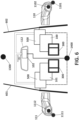
- Figure 1 presents a motor vehicle (10) with a camera monitoring system, CMS, which comprises image capturing means (e.g., a camera) configured to captures images, the image capturing means being associated with an exterior mounting assembly (e.g., a winglet or a sharkfin), the mounting assembly being located at an exterior part of the (body side of the) motor vehicle (10).
- the image capturing means can be located, even fixed, outside the vehicle (10).
- the image capturing means are configured to capture an image from an exterior field of view of the motor vehicle (10), wherein the field of view extends at least sideward and rearward outside the vehicle (10). This field of view also encompasses a portion of the exterior side part of the vehicle (10) body at which the mounting assembly is located.
- the image capturing means can capture a field of view extended at least 20 meters rearward and 4 meters sidewards.
- Figure 1 shows two exterior rear-view mirrors (110, 111) at each side of the motor vehicle (10) and an interior rear-view mirror (112).
- Any of the exterior rear-view mirrors (110, 111) can be a (mechanically) mobile winglet or can be fixed (not mobile). In the case of being fixed, one option is to use a (i) winglet, which may be extendible; or (ii) a "sharkfin", more specifically, having two cameras (one for the top-view and one for the CMS) in the same mounting assembly housing.
- the CMS for the vehicle (10) shown in Figure 1 comprises image capturing means located outside and associated with the exterior rear-view mirrors (110, 111); there is no image capturing means for the interior rear-view mirror (112).
- the CMS further comprises an electronic control unit or ECU connected to the image capturing means, configured to select an image region from the image captured by the image capturing means.
- the image region is smaller than the captured image; i.e., is obtained by cropping the image from the image capturing means.
- the CMS further comprises at least one (first) display device (100, 101, 102) located inside the motor vehicle (10), for example as shown in Figure 1 , and connected to the electronic control unit.
- the ECU inputs the image region into the display device (100, 101, 102) to be displayed as a cropped image instead of displaying the entire captured image. That is, the ECU does not input the whole captured image into the display device (100, 101, 102).
- said image region can be moved within the captured image in response to a user's action, which can be: i) a touch by the user on a control surface of the display device (100, 101, 102) and/or ii) a gesture made by the user to a gesture detector that can be implemented in said display device (100, 101, 102) or by another device using any gesture detection technology.
- a user's action can be: i) a touch by the user on a control surface of the display device (100, 101, 102) and/or ii) a gesture made by the user to a gesture detector that can be implemented in said display device (100, 101, 102) or by another device using any gesture detection technology.
- the control surface can be implemented in a touch screen (200) of the (first) display device (100, 101, 102) preferably working as a multi-touch-sensitive display configured to receive a user's touch so as to move the image region within the captured image.
- the touch screen (200) is configured to detect different places touched simultaneously, in particular by a finger.
- the multi-touch-sensitive display allows tracking of images and touch carried out not only by one finger, but also complex actions, requiring operation with two or more fingers, can be performed.
- the multi-touch-sensitive display may be further provided with a magnification of image regions by using two fingers and a change in the spacing of the fingers during contact is adjustable.
- the CMS comprises an associated touch screen controller configured to detect also movements and / or touches of one or more fingers by increasing the sensitive capacity of the touch screen (200).
- the touch screen (200) in an interior part of the motor vehicle (10), can be provided for only one of the exterior (or wing) rear-view mirrors (110, 111).
- the touch screen (200) at least one parameter of the one exterior rear-view mirror (110, 111), in particular an operation parameter related to pivoting of the external camera and/or presentation parameters of an image section/region of the image captured by the external camera, can be adjusted.
- the touch screen (200) can be additionally arranged for an interior rear-view mirror (112) in an interior part of the motor vehicle (10).
- the interior rear-view mirror (112) and the exterior rear-view mirrors (110, 111) are connected through the ECU of the vehicle (10).
- the multi-touch-sensitive screen (200) of the display device (100, 101, 102) can be configured to be an "only-touch” screen. That is, instead of having a "touch and drag” screen, the CMS provides the touch screen (200) with two different portions as the ECU (500) distinguishes: a first portion of the touch screen (200) in which the user/driver is not enabled to perform "touch and drag” of the displayed image, and a second portion in which the user/driver can perform normally the "touch and drag” operation provided by the multi-touch-sensitive screen (200).
- the user can perform only "touch” in the first portion or "touch & dragg" in the second portion.
- the technical advantage of doing so is that the first portion does not get dirty.
- the light (image) received by the second portion comes from the same image of the display as the first portion.
- the first portion is larger than the second portion.
- the area of the second portion is approximately 30% of that of the first portion.
- the length of the second portion is 20% of the length of the first portion, the length being defined along an X (horizontal) axis.
- a single touch screen (200) on each side of the vehicle (10) is connected to the ECU (500), which distinguishes between a first portion (2001) and a second portion (2002) of the touch screen (200), as shown in Figure 2 .
- the ECU deactivates the first portion (2001) of the touch screen (200) so that the user cannot do the "touch and drag” in said first portion (2001) working as an "only-touch” screen, while the "touch and drag” is activated by the ECU only in the second portion (2002).
- the ECU can even deactivate the entire "touch" function in the first portion (2001) of the touch screen (200).
- the user is enabled to use the second portion (2002) to adjust the FOV and the brightness and/or contrast and/or color parameters of the image region displayed in the first portion (2001).
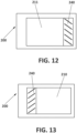
- the CMS further comprises a frame (300) covering partially the first display device (100, 101, 102), as shown in Figures 3-4 .
- a housing (600) which is adapted to be coupled with fixing means (610), to fix a controller or ECU (500), a touch screen (200) and the frame (300), to the door or anywhere inside the vehicle (10).
- the frame can be partially tinted; more particularly, comprising a (first) section that is not tinted, while the rest of the frame is stained.
- the transparent or non-tinted portion of the frame from which the light of the display comes out and becomed visible by the user, can present different forms. Therefore, only the section of the frame (image) that is not tinted is shown/perceived to/by the user, but not all the image emitted by the display.
- (the first) non-tinted section of the frame has a size of approximately 60% of the total screen (200) and, preferably, its geometry (200) is rectangular. The geometry of the non-tinted section is purely aesthetic.
- the first display device (100, 101, 102) has an additional, second screen (400) in addition to the multi-touch-sensitive screen (200).
- the first portion (2001) distinguised by the ECU (500) can be implemented in the second screen (400), which can be touchless and then cheaper, and the second portion (2002) in the touch screen (200) without requiring to deactivate the "touch and drag".
- this second portion (2002) implemented in the touch screen (200), preferably smaller than the touchless screen can display the parameters related to brightness and/or contrast and/or color of the additional screen to be adjusted by user's touch.
- One technical advantage is the cost of non-touch-sensitive screens.
- the CMS can take advantage of the second portion (2002) (implemented in a single touch screen (200) or in an additional screen as described before) to indicate a Blind Spot Detection or BSD, i.e., if an object is detected in the blind spot, the CMS turns on an indicator (triangle, exclamation, etc.) in said second portion (2002) of the first display device (100, 101, 102).
- BSD Blind Spot Detection
- the CMS can be additionally provided with at least one (second) display device (another touch screen) to display parameters of the first display device (100, 101, 102), i.e., operation parameters of the touch screen (200).
- the first display device (100, 101, 102) itself can also display the parameters to be adjusted.
- the touch screen (200) allows the user by his/her touch to set brightness and/or contrast and/or color parameters of the first display device (100, 101, 102). Therefore, parameters are adjustable directly on the touch screen of the display device with respect to the optical impression of the image display parameters shown on the display.
- the driver can make the image lighter or darker, to choose contrast and other common parameters, in particular color-related parameter set of the images displayed in the touch screen (200).
- the CMS is designed for inserting or superimposing a slider bar for the presentation parameters on the display device.
- At least one operating parameter of the first display device can be used by the CMS to output an item of information and/or a warning, in particular to be used by a driver's assistance system (e.g., a lane change assistance system and/or a blind spot assistance system and/or parking assistance and/or a reversing assistance system) provided in the vehicle (10).
- a driver's assistance system e.g., a lane change assistance system and/or a blind spot assistance system and/or parking assistance and/or a reversing assistance system
- the output of this information and/or a warning is adjustable depending upon an input on the touch screen (200).
- At least one item of additional information can be superimposed into the image displayed on the touch screen (200) and can be moved, by interaction at the display location of the additional information in the touch screen (200).
- context-sensitive menus of items which can be activated by the touch screen (200) and displayed on the display device (100, 101, 102).
- the ECU (500) or control unit can provide some digital buttons to be overlaid on the image shown in a second portion (2002) of the touch screen (200). For example, after selecting a specific adjustment possibility which can be done through a menu and / or a depicted control, thus a slider is displayed on the control surface of the touch screen (200), which can be gripped, for example by contact at the position of the slider and manipulated to adjust the display parameters.
- a slider is displayed on the control surface of the touch screen (200), which can be gripped, for example by contact at the position of the slider and manipulated to adjust the display parameters.
- the presentation parameter set for example with "+" and / or "-" labeled on the display area on-screen controls that trigger corresponding to an increase or decrease of the presentation parameter if a touch is sensed (zoom function).
- the control unit can be configured to form a touch screen menu on the screen (200).
- a menu can be displayed, which allows the setting of parameters of the winglet.
- the driver can touch with a finger (or with a pen) the image portion on one of the labelled symbols and cause a setting menu open different options (or additional information) in the image portion. Therefore, overlaid symbols are then placed with a menu having multiple menu items related to display parameters; in particular, for contrast, brightness and color parameters. It is also conceivable that by tapping the touch screen shown outside controls / menu items return to the default display. Additionally, touching the additional information can result in a corresponding menu with settings concerning the lane change assistant, i.e., in particular operating parameters of the lane change assistant.
- buttons (310) are drawn on the frame (300), as depicted in Figure 5 , so that the user can touch the drawn button (the button is not a mechanical component that moves) to trigger digital buttons on the screen (200).
- the frame and the screen (200) are together and in contact.
- a joystick including the typical mouse ball (not optical) for computers or physical push buttons can be used.
- the joystick and/or the push buttons can be located anywhere the driver has access when driving; for example, on the door, on the dashboard (central console), on the steering wheel, etc.
- the push buttons can have a cross-shaped distribution, in order to move up / down / left / right.
- the joystick can have a cross or circular movement which allows the image to be moved according to the movement of the joystick.
- FIG 6 shows the image capturing means used by the CMS, which can be an external camera (1102, 1112) rearwardly oriented and located at opposite sides (outside) of the vehicle (10), for capturing the external environment.
- Each CMS camera (1102, 1112) is fixed on an exterior rear-view mirror (110, 111) which is a winglet, and preferably the winglet is fixed to the outside of the car door (601, 602).
- the winglets at both side of the vehicle (10) incorporate respective top-view cameras (1101, 1111), but none of them are used by the CMS.
- the vehicle (10) has a front camera (1300) and rear camera (1400), used by the ECU (500) to do the top-view by stitching.
- a touch screen (200), e.g. of the left display device (101) can control the image region, e.g. the field of view adjustment, displayed in another screen / portion of the left display device (101).
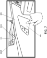
- Figure 7 shows the left exterior rear-view mirror (110) which is a winglet fixed on the outer side of the left door (601) and incorporates two fixed cameras: a first camera down for the top-view (1111) and a second camera focused back for the CMS (1112).
- the left display device (101) is fixed on the other, the inner, side of the left door (601) so that the user, the driver usually, can adjust the FOV of the CMS camera by touches.
- the top-view camera (1111) is usually positioned with a relative angle (e.g., around 2° - 20°) from the perpendicular to the ground and said angle varies according to the model of the vehicle (length of the car, height of the car, shape of the external surface where the mounted assembly housing is placed on, e.g., shape of the door, etc.).
- a relative angle e.g., around 2° - 20°
- each - right, left - winglet of the CMS can comprise:
- Figure 8 shows the touch screen (200) of the left display device (101) normally used by the driver
- Figure 9 shows the touch screen (200) of the right display device (100), typically fixed at the co-driver's side.
- the second portion of the display devices (100, 101), implemented in the touch screen (200) displays an image region (210, 211) of the image captured by the respective external CMS cameras (1102, 1112).
- a zoom level of the image region (210, 211) is adjustable by positioning two fingers on the touch screen (200) and changing the distance between the fingers whilst touching.
- the image region (211) displayed in the second portion of the left display device (101) may further comprise an additional image section (232), as shown in Figure 11 , obtained by the ECU (500), which selects the extreme side of the image (231), shown in Figure 10 , captured by the left external CMS camera (1112) and reduces its width.
- the additional image section (232) shown in Figure 11 corresponds to the narrowed image of the extreme side of the captured image (231) shown in Figure 10 , increasing significantly the FOV of the left external CMS camera (1112) simulating an aspherical view mirror in the left exterior rear-view mirror (110).
- the touch screen (200) presents a third additional image section (240), which shows the image captured by the rear camera (1400), displayed at the side opposite to the image region (210, 211) of the image captured by the respective external CMS cameras (1102, 1112).
- This third additional image section (240, 241) allows the driver to see behind the vehicle through the display devices (100, 101) associated with the exterior rear-view mirrors (110, 111), which minimizes the number of displays required.
- the third additional image section (240) is shown on the second portion (2002) of the display device.
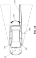
- the driver can see the adjacent area (1222) of the "side zone view", i.e., the zone between the "rear zone” (1220) and the “side zone” (1221), as shown in Figure 14 , in a "single” image on the driver's display, typically the one associated with the left exterior rear-view mirror (111).
- the image from the corresponding top view camera (1101, 1111) of the display devices (100, 101) can be taken.
- This is useful when the image region (210, 211), as being moved inside the captured image, can reach reach an edge (extreme) of the captured image.
- the ECU (500) detects it and selects the "top view” image to be shown on the second portion (2002).
- the ECU (500) can select: (i) the topview of the top-view camera of a single CMS device; or (ii) the top-view of the surrounding view, that is, after doing the "stitching" of the four top-view images from left, right, front and rear cameras.
- the image from the area (1222) captured by the rear camera (1400) i.e., it is not all the rear image, but the portion of the adjacent/complementary rear image, can be displayed on the second portion (2002) or second screen (400).
- the display devices (100, 101, 102) can be controlled by the user, driver or co-driver, from a smartphone or tablet, e.g., via Bluetooth.
- the CMS can automatically load the settings previously input by the driver (i.e., user preferences of the device owner: default position, views ...) into his/her smartphone or tablet to the ECU (500).
- the controller or ECU (500) of the CMS is configured also to receive and process vehicle driving and/or user information, and the image region (210, 211) is moved within the captured image depending on said received information.
- vehicle driving information at least corresponds to a change in driving direction from a forward driving direction to a reverse driving direction or vice versa, an increase or decrease in driving speed with respect to a predefined driving speed value, a lane change, a change in steering angle, a change in pitch angle, a change in roll angle, and road monitoring information.
- the ECU (500) is further configured to:
- the ECU (500) is configured to determine a relative upward and downward movement of the exterior rear-view mirror (110, 111) from a change in the pitch angle value, and further configured to:
- the ECU (500) is configured to move the image region (210, 211) such that the zoom of the displayed image increases when the driving speed is increased and such that it surpasses the predefined driving speed value, while the image region area is decreased when the vehicle speed falls below a predefined driving speed value.
- a smaller part of the captured image is selected as image region (210, 211), and then an enlarged image is displayed when over speed is detected by the ECU (500).
- the driver has a better view of the area of interest, which in this case, corresponds to a more detailed view of the farthest area from the vehicle.
- the ECU (500) is configured to receive an activation signal such a blinker, and further configured to move the image region (210, 211) upon receiving said activation signal.
- an activation signal such as a blinker
- the CMS can work with speed or other measurements (e.g., if the reverse gear is engaged in parking situations) obtained from the CAN, or another network (e.g., Ethernet, etc.) which the ECU (500) is communicated with.
- the same measured speed signal can be used to adjust the FOV of the entire system in the vehicle (10), shown in Figures 1 and 6 , comprising: a "right CMS" corresponding to the camera/s or image processing means (1102) associated with the right left exterior rear-view mirror (110, 111), a "left CMS” corresponding to the camera/s or image processing means (1112) associated with the left exterior rear-view mirror (111) and an intelligent interior rear-view mirror system or IRMS associated with the interior rear-view mirror (112).
- the IRMS and the CMSs are controlled by the same ECU (500).
- the ECU (500) can be configured to compare current images with previous images to act as a "back up" in case the CAN does not work (because there are wireless cameras that cannot be physically connected to the CAN, or because the CAN is damaged or because there are values that are not transmitted correctly through the CAN).
- the CMS can store images in case of accident detection.
- the ECU (500) can be connected to the CAN of the car and the CAN itself that determines when there is an accident or not.
- the ECU (500) also comprises accident detection means.
- said accident detection means comprise an accelerometer. This accelerometer is configured so that it never jumps in maximum acceleration of the car or a braking, but when there is a shock where the deceleration is greater. In any case, the images are not hidden with overlays of digital buttons.
- the driver can adjust the FOV of the IRMS through the "touch & dragg", preferably provided by the second portion (2002) of the CMS display device (100, 101, 102). While traditional central rear-view mirrors are tilted because the driver is on the left side of the car and wants to see what is behind, the interior mirrors of the IRMS, which provides the driver with a display showing the image of the rear camera (1400), are centered. There is no option to turn the rear view mirror in the IRMS, but the driver can perform a "crop & pan" of the rear camera through the "touch & dragg" functionality in the second portion (2002).
- the rear camera (1400) captures an image, in which a controller -either a single ECU of the vehicle, any of the CMS's ECUs (500), or the IRMS's ECU- selects a portion of the image or "image region" that appears on the IRMS display.
- the CMS comprises, as alternative to the before described approach based on a control surface of the touch screen or in addition to it, a gesture detector so as, for example, to move the image region within the image captured by the exterior image capturing means by gestures of the driver's fingers or to allow the driver command the CMS to expand the FOV by a head movement.
- a gesture detector so as, for example, to move the image region within the image captured by the exterior image capturing means by gestures of the driver's fingers or to allow the driver command the CMS to expand the FOV by a head movement.
- the crop-and-pan functionality may be triggered by a driver's head movement.
- the driver's head movement may be tracked by a surveillance system, which is preferably within the vehicle, more preferably fixed (i) in front of the driver, or (ii) in the interior rear-view mirror, (iii) or near to the CMS display device.
- the driver surveillance system may comprise a camera.
- the surveillance system may be capable of working out the position and distance of the driver's head.
- the image region region (210, 211) within the captured image may be manually controlled (e.g., by screen sliding command o by the touch-and-dragg functionality), but also by the driver's head moving forward when this movement is captured by the gesture detector.
Landscapes
- Engineering & Computer Science (AREA)
- Multimedia (AREA)
- Mechanical Engineering (AREA)
- Chemical & Material Sciences (AREA)
- Combustion & Propulsion (AREA)
- Transportation (AREA)
- Theoretical Computer Science (AREA)
- Physics & Mathematics (AREA)
- General Physics & Mathematics (AREA)
- General Engineering & Computer Science (AREA)
- Human Computer Interaction (AREA)
- General Health & Medical Sciences (AREA)
- Psychiatry (AREA)
- Social Psychology (AREA)
- Computer Vision & Pattern Recognition (AREA)
- Health & Medical Sciences (AREA)
- Signal Processing (AREA)
- Closed-Circuit Television Systems (AREA)
Priority Applications (4)
| Application Number | Priority Date | Filing Date | Title |
|---|---|---|---|
| EP19382531.2A EP3756949B1 (en) | 2019-06-24 | 2019-06-24 | Camera monitoring system for motor vehicles |
| US16/910,980 US20200401818A1 (en) | 2019-06-24 | 2020-06-24 | Camera monitroing system for motor vehicles |
| CN202010589103.1A CN112135089B (zh) | 2019-06-24 | 2020-06-24 | 用于机动车辆的摄像机监控系统 |
| JP2020109191A JP7582801B2 (ja) | 2019-06-24 | 2020-06-24 | 自動車用のカメラ監視システム |
Applications Claiming Priority (1)
| Application Number | Priority Date | Filing Date | Title |
|---|---|---|---|
| EP19382531.2A EP3756949B1 (en) | 2019-06-24 | 2019-06-24 | Camera monitoring system for motor vehicles |
Publications (2)
| Publication Number | Publication Date |
|---|---|
| EP3756949A1 EP3756949A1 (en) | 2020-12-30 |
| EP3756949B1 true EP3756949B1 (en) | 2024-12-25 |
Family
ID=67060354
Family Applications (1)
| Application Number | Title | Priority Date | Filing Date |
|---|---|---|---|
| EP19382531.2A Active EP3756949B1 (en) | 2019-06-24 | 2019-06-24 | Camera monitoring system for motor vehicles |
Country Status (4)
| Country | Link |
|---|---|
| US (1) | US20200401818A1 (enExample) |
| EP (1) | EP3756949B1 (enExample) |
| JP (1) | JP7582801B2 (enExample) |
| CN (1) | CN112135089B (enExample) |
Families Citing this family (10)
| Publication number | Priority date | Publication date | Assignee | Title |
|---|---|---|---|---|
| FR3111308B1 (fr) * | 2020-06-15 | 2025-01-10 | Psa Automobiles Sa | Procédé et dispositif de réglage de fonctions de confort et/ou de sécurité d’un véhicule |
| KR20220053092A (ko) * | 2020-10-21 | 2022-04-29 | 현대모비스 주식회사 | 운전자를 위한 주행 보조 시스템 및 방법 |
| WO2022140161A1 (en) * | 2020-12-23 | 2022-06-30 | Stoneridge Electronics Ab | Camera mirror system with outside air temperature sensor |
| WO2022246391A1 (en) * | 2021-05-17 | 2022-11-24 | Atieva, Inc. | Vehicle display device |
| EP4219237A1 (en) * | 2022-01-26 | 2023-08-02 | Ficosa Adas, S.L.U. | Rear-view mirror system |
| US11926258B2 (en) | 2022-03-24 | 2024-03-12 | Honda Motor Co., Ltd. | Vehicle ambient lighting |
| KR20240071835A (ko) * | 2022-11-16 | 2024-05-23 | 현대자동차주식회사 | 디지털 사이드 미러 시스템의 터치 패널과 연동되는 조작 스위치를 구비한 차량 제어 장치 및 방법 |
| CN119160089A (zh) * | 2023-06-20 | 2024-12-20 | 新加坡商群丰骏科技股份有限公司 | 车用装置及其操作方法 |
| WO2025157758A1 (en) * | 2024-01-25 | 2025-07-31 | Stoneridge Electronics Ab | Systems and methods for steering wheel-based control of camera monitor system |
| WO2025232972A1 (en) * | 2024-05-08 | 2025-11-13 | Stoneridge Electronics Ab | Camera monitoring system including hmi-based panning features |
Citations (3)
| Publication number | Priority date | Publication date | Assignee | Title |
|---|---|---|---|---|
| EP2181892A1 (de) * | 2008-10-28 | 2010-05-05 | Volkswagen AG | Parkassistenzsystem und Verfahren zum Betreiben eines Parkassistenzsystems für ein Kraftfahrzeug |
| US20130128047A1 (en) * | 2011-11-23 | 2013-05-23 | Hyundai Motor Company | Touch type display mirror |
| US20230234510A1 (en) * | 2022-01-26 | 2023-07-27 | Ficosa Adas, S.L.U. | Rear-view mirror system |
Family Cites Families (19)
| Publication number | Priority date | Publication date | Assignee | Title |
|---|---|---|---|---|
| KR100827228B1 (ko) * | 2006-05-01 | 2008-05-07 | 삼성전자주식회사 | 터치 기능을 갖는 영역 분할 수단을 제공하는 장치 및 그방법 |
| US8259208B2 (en) * | 2008-04-15 | 2012-09-04 | Sony Corporation | Method and apparatus for performing touch-based adjustments within imaging devices |
| US20140285666A1 (en) | 2011-11-01 | 2014-09-25 | Magna Mirrors Of America, Inc. | Vision system with door mounted exterior mirror and display |
| US20150212647A1 (en) * | 2012-10-10 | 2015-07-30 | Samsung Electronics Co., Ltd. | Head mounted display apparatus and method for displaying a content |
| DE102013002891A1 (de) * | 2013-03-22 | 2014-09-25 | Volkswagen Aktiengesellschaft | Informationswiedergabesystem für ein Fahrzeug und Verfahren zum Bereitstellen von Informationen für den Benutzer eines Fahrzeugs |
| JP6315456B2 (ja) | 2013-05-21 | 2018-04-25 | カルソニックカンセイ株式会社 | タッチパネル式の車両用情報表示装置 |
| US9701258B2 (en) * | 2013-07-09 | 2017-07-11 | Magna Electronics Inc. | Vehicle vision system |
| JP6342704B2 (ja) * | 2014-05-12 | 2018-06-13 | 矢崎総業株式会社 | 表示装置 |
| JP2016103743A (ja) | 2014-11-28 | 2016-06-02 | 株式会社翔栄 | タッチスイッチ及び画像表示装置 |
| KR101643557B1 (ko) * | 2015-01-02 | 2016-07-29 | 현대자동차주식회사 | 차량 및 차량의 제어방법 |
| CN107848465B (zh) * | 2015-05-06 | 2021-06-01 | 麦格纳镜片美国有限公司 | 具有盲区显示和警示系统的车辆视觉系统 |
| KR102436513B1 (ko) * | 2015-08-12 | 2022-08-26 | 삼성전자 주식회사 | 전자 기기의 해상도 조정 방법 및 장치 |
| CN106853795A (zh) * | 2015-12-08 | 2017-06-16 | 余嘉伟 | 一种可看得更远的后视镜头 |
| US10589676B2 (en) * | 2016-06-02 | 2020-03-17 | Magna Electronics Inc. | Vehicle display system with user input display |
| US10025424B2 (en) * | 2016-08-15 | 2018-07-17 | Ford Global Technologies, Llc | Vehicle with headlight control |
| JP2018103866A (ja) | 2016-12-27 | 2018-07-05 | 株式会社東海理化電機製作所 | 車両用視認装置 |
| JP6539684B2 (ja) * | 2017-01-31 | 2019-07-03 | 矢崎総業株式会社 | 車両用表示装置および車両用表示装置の表示方法 |
| JP6889587B2 (ja) * | 2017-03-31 | 2021-06-18 | 株式会社Subaru | 画像表示装置 |
| US10310323B1 (en) * | 2018-02-12 | 2019-06-04 | Visteon Global Technologies, Inc. | Bright panel display cluster |
-
2019
- 2019-06-24 EP EP19382531.2A patent/EP3756949B1/en active Active
-
2020
- 2020-06-24 JP JP2020109191A patent/JP7582801B2/ja active Active
- 2020-06-24 CN CN202010589103.1A patent/CN112135089B/zh active Active
- 2020-06-24 US US16/910,980 patent/US20200401818A1/en active Pending
Patent Citations (3)
| Publication number | Priority date | Publication date | Assignee | Title |
|---|---|---|---|---|
| EP2181892A1 (de) * | 2008-10-28 | 2010-05-05 | Volkswagen AG | Parkassistenzsystem und Verfahren zum Betreiben eines Parkassistenzsystems für ein Kraftfahrzeug |
| US20130128047A1 (en) * | 2011-11-23 | 2013-05-23 | Hyundai Motor Company | Touch type display mirror |
| US20230234510A1 (en) * | 2022-01-26 | 2023-07-27 | Ficosa Adas, S.L.U. | Rear-view mirror system |
Also Published As
| Publication number | Publication date |
|---|---|
| JP7582801B2 (ja) | 2024-11-13 |
| JP2021000984A (ja) | 2021-01-07 |
| US20200401818A1 (en) | 2020-12-24 |
| CN112135089A (zh) | 2020-12-25 |
| CN112135089B (zh) | 2025-04-08 |
| EP3756949A1 (en) | 2020-12-30 |
Similar Documents
| Publication | Publication Date | Title |
|---|---|---|
| EP3756949B1 (en) | Camera monitoring system for motor vehicles | |
| CN110395182B (zh) | 具有电子后视镜的机动车 | |
| US11124118B2 (en) | Vehicular display system with user input display | |
| KR102312455B1 (ko) | 이동 수단의 부품의 전동식 조절을 위한 스위치의 조작 전에 사용자를 지원하기 위한 장치 및 방법 | |
| US11694448B2 (en) | Camera monitoring system for motor vehicles | |
| US11003242B2 (en) | Eye tracking | |
| CN107054222B (zh) | 一种用于机动车辆的后视系统 | |
| US9965169B2 (en) | Systems, methods, and apparatus for controlling gesture initiation and termination | |
| US10481757B2 (en) | Eye gaze control system | |
| JP2021000984A5 (enExample) | ||
| US20140195096A1 (en) | Apparatus and method for contactlessly detecting objects and/or persons and gestures and/or operating procedures made and/or carried out thereby | |
| CN103373294B (zh) | 用于显示车辆操作元件的操作者的手的方法和装置 | |
| EP3457254A1 (en) | Method and system for displaying virtual reality information in a vehicle | |
| KR101946746B1 (ko) | 차량에서 비-차량 오브젝트의 위치 결정 | |
| WO2013101067A1 (en) | Systems and methods for enhanced display images | |
| CN105144070A (zh) | 用于在车辆中提供图形用户界面的方法和装置 | |
| CN115848271A (zh) | 驻车显示方法、车辆终端、车辆及产品 | |
| WO2018126257A1 (en) | Automatic eye box adjustment | |
| JP2015080994A (ja) | 車両用情報処理装置 | |
| KR20130031653A (ko) | 차량용 후방감지 카메라의 시야각 조절 시스템 | |
| DE102016224235A1 (de) | Verfahren und Vorrichtung zur Anpassung der Darstellung von Bild- und/oder Bedienelementen auf einer grafischen Benutzerschnittstelle | |
| US20220258760A1 (en) | Rearview System for a Vehicle with Collision Detection | |
| EP3663120B1 (en) | Method and associated device for controlling at least one parameter of a vehicle | |
| JP2010235065A (ja) | 車両用シート駆動装置 | |
| JP2022070378A (ja) | 車両表示装置 |
Legal Events
| Date | Code | Title | Description |
|---|---|---|---|
| PUAI | Public reference made under article 153(3) epc to a published international application that has entered the european phase |
Free format text: ORIGINAL CODE: 0009012 |
|
| STAA | Information on the status of an ep patent application or granted ep patent |
Free format text: STATUS: THE APPLICATION HAS BEEN PUBLISHED |
|
| AK | Designated contracting states |
Kind code of ref document: A1 Designated state(s): AL AT BE BG CH CY CZ DE DK EE ES FI FR GB GR HR HU IE IS IT LI LT LU LV MC MK MT NL NO PL PT RO RS SE SI SK SM TR |
|
| AX | Request for extension of the european patent |
Extension state: BA ME |
|
| STAA | Information on the status of an ep patent application or granted ep patent |
Free format text: STATUS: REQUEST FOR EXAMINATION WAS MADE |
|
| 17P | Request for examination filed |
Effective date: 20210630 |
|
| RBV | Designated contracting states (corrected) |
Designated state(s): AL AT BE BG CH CY CZ DE DK EE ES FI FR GB GR HR HU IE IS IT LI LT LU LV MC MK MT NL NO PL PT RO RS SE SI SK SM TR |
|
| STAA | Information on the status of an ep patent application or granted ep patent |
Free format text: STATUS: EXAMINATION IS IN PROGRESS |
|
| 17Q | First examination report despatched |
Effective date: 20211115 |
|
| GRAP | Despatch of communication of intention to grant a patent |
Free format text: ORIGINAL CODE: EPIDOSNIGR1 |
|
| STAA | Information on the status of an ep patent application or granted ep patent |
Free format text: STATUS: GRANT OF PATENT IS INTENDED |
|
| RIC1 | Information provided on ipc code assigned before grant |
Ipc: B60K 35/00 20060101ALI20240613BHEP Ipc: B60R 1/00 20060101AFI20240613BHEP |
|
| INTG | Intention to grant announced |
Effective date: 20240715 |
|
| GRAS | Grant fee paid |
Free format text: ORIGINAL CODE: EPIDOSNIGR3 |
|
| GRAA | (expected) grant |
Free format text: ORIGINAL CODE: 0009210 |
|
| STAA | Information on the status of an ep patent application or granted ep patent |
Free format text: STATUS: THE PATENT HAS BEEN GRANTED |
|
| AK | Designated contracting states |
Kind code of ref document: B1 Designated state(s): AL AT BE BG CH CY CZ DE DK EE ES FI FR GB GR HR HU IE IS IT LI LT LU LV MC MK MT NL NO PL PT RO RS SE SI SK SM TR |
|
| REG | Reference to a national code |
Ref country code: GB Ref legal event code: FG4D |
|
| REG | Reference to a national code |
Ref country code: CH Ref legal event code: EP |
|
| REG | Reference to a national code |
Ref country code: DE Ref legal event code: R096 Ref document number: 602019063907 Country of ref document: DE |
|
| REG | Reference to a national code |
Ref country code: IE Ref legal event code: FG4D |
|
| REG | Reference to a national code |
Ref country code: LT Ref legal event code: MG9D |
|
| PG25 | Lapsed in a contracting state [announced via postgrant information from national office to epo] |
Ref country code: FI Free format text: LAPSE BECAUSE OF FAILURE TO SUBMIT A TRANSLATION OF THE DESCRIPTION OR TO PAY THE FEE WITHIN THE PRESCRIBED TIME-LIMIT Effective date: 20241225 |
|
| PG25 | Lapsed in a contracting state [announced via postgrant information from national office to epo] |
Ref country code: BG Free format text: LAPSE BECAUSE OF FAILURE TO SUBMIT A TRANSLATION OF THE DESCRIPTION OR TO PAY THE FEE WITHIN THE PRESCRIBED TIME-LIMIT Effective date: 20241225 |
|
| PG25 | Lapsed in a contracting state [announced via postgrant information from national office to epo] |
Ref country code: NO Free format text: LAPSE BECAUSE OF FAILURE TO SUBMIT A TRANSLATION OF THE DESCRIPTION OR TO PAY THE FEE WITHIN THE PRESCRIBED TIME-LIMIT Effective date: 20250325 |
|
| PG25 | Lapsed in a contracting state [announced via postgrant information from national office to epo] |
Ref country code: GR Free format text: LAPSE BECAUSE OF FAILURE TO SUBMIT A TRANSLATION OF THE DESCRIPTION OR TO PAY THE FEE WITHIN THE PRESCRIBED TIME-LIMIT Effective date: 20250326 Ref country code: LV Free format text: LAPSE BECAUSE OF FAILURE TO SUBMIT A TRANSLATION OF THE DESCRIPTION OR TO PAY THE FEE WITHIN THE PRESCRIBED TIME-LIMIT Effective date: 20241225 |
|
| PG25 | Lapsed in a contracting state [announced via postgrant information from national office to epo] |
Ref country code: RS Free format text: LAPSE BECAUSE OF FAILURE TO SUBMIT A TRANSLATION OF THE DESCRIPTION OR TO PAY THE FEE WITHIN THE PRESCRIBED TIME-LIMIT Effective date: 20250325 |
|
| REG | Reference to a national code |
Ref country code: NL Ref legal event code: MP Effective date: 20241225 |
|
| PG25 | Lapsed in a contracting state [announced via postgrant information from national office to epo] |
Ref country code: NL Free format text: LAPSE BECAUSE OF FAILURE TO SUBMIT A TRANSLATION OF THE DESCRIPTION OR TO PAY THE FEE WITHIN THE PRESCRIBED TIME-LIMIT Effective date: 20241225 |
|
| REG | Reference to a national code |
Ref country code: AT Ref legal event code: MK05 Ref document number: 1753914 Country of ref document: AT Kind code of ref document: T Effective date: 20241225 |
|
| PG25 | Lapsed in a contracting state [announced via postgrant information from national office to epo] |
Ref country code: SM Free format text: LAPSE BECAUSE OF FAILURE TO SUBMIT A TRANSLATION OF THE DESCRIPTION OR TO PAY THE FEE WITHIN THE PRESCRIBED TIME-LIMIT Effective date: 20241225 |
|
| PG25 | Lapsed in a contracting state [announced via postgrant information from national office to epo] |
Ref country code: PL Free format text: LAPSE BECAUSE OF FAILURE TO SUBMIT A TRANSLATION OF THE DESCRIPTION OR TO PAY THE FEE WITHIN THE PRESCRIBED TIME-LIMIT Effective date: 20241225 |
|
| PGFP | Annual fee paid to national office [announced via postgrant information from national office to epo] |
Ref country code: DE Payment date: 20250618 Year of fee payment: 7 |
|
| PG25 | Lapsed in a contracting state [announced via postgrant information from national office to epo] |
Ref country code: ES Free format text: LAPSE BECAUSE OF FAILURE TO SUBMIT A TRANSLATION OF THE DESCRIPTION OR TO PAY THE FEE WITHIN THE PRESCRIBED TIME-LIMIT Effective date: 20241225 |
|
| PG25 | Lapsed in a contracting state [announced via postgrant information from national office to epo] |
Ref country code: IS Free format text: LAPSE BECAUSE OF FAILURE TO SUBMIT A TRANSLATION OF THE DESCRIPTION OR TO PAY THE FEE WITHIN THE PRESCRIBED TIME-LIMIT Effective date: 20250425 |
|
| PG25 | Lapsed in a contracting state [announced via postgrant information from national office to epo] |
Ref country code: PT Free format text: LAPSE BECAUSE OF FAILURE TO SUBMIT A TRANSLATION OF THE DESCRIPTION OR TO PAY THE FEE WITHIN THE PRESCRIBED TIME-LIMIT Effective date: 20250428 |
|
| PG25 | Lapsed in a contracting state [announced via postgrant information from national office to epo] |
Ref country code: EE Free format text: LAPSE BECAUSE OF FAILURE TO SUBMIT A TRANSLATION OF THE DESCRIPTION OR TO PAY THE FEE WITHIN THE PRESCRIBED TIME-LIMIT Effective date: 20241225 |
|
| PG25 | Lapsed in a contracting state [announced via postgrant information from national office to epo] |
Ref country code: RO Free format text: LAPSE BECAUSE OF FAILURE TO SUBMIT A TRANSLATION OF THE DESCRIPTION OR TO PAY THE FEE WITHIN THE PRESCRIBED TIME-LIMIT Effective date: 20241225 Ref country code: AT Free format text: LAPSE BECAUSE OF FAILURE TO SUBMIT A TRANSLATION OF THE DESCRIPTION OR TO PAY THE FEE WITHIN THE PRESCRIBED TIME-LIMIT Effective date: 20241225 |
|
| PG25 | Lapsed in a contracting state [announced via postgrant information from national office to epo] |
Ref country code: SK Free format text: LAPSE BECAUSE OF FAILURE TO SUBMIT A TRANSLATION OF THE DESCRIPTION OR TO PAY THE FEE WITHIN THE PRESCRIBED TIME-LIMIT Effective date: 20241225 |
|
| PG25 | Lapsed in a contracting state [announced via postgrant information from national office to epo] |
Ref country code: CZ Free format text: LAPSE BECAUSE OF FAILURE TO SUBMIT A TRANSLATION OF THE DESCRIPTION OR TO PAY THE FEE WITHIN THE PRESCRIBED TIME-LIMIT Effective date: 20241225 |
|
| PG25 | Lapsed in a contracting state [announced via postgrant information from national office to epo] |
Ref country code: IT Free format text: LAPSE BECAUSE OF FAILURE TO SUBMIT A TRANSLATION OF THE DESCRIPTION OR TO PAY THE FEE WITHIN THE PRESCRIBED TIME-LIMIT Effective date: 20241225 |
|
| PG25 | Lapsed in a contracting state [announced via postgrant information from national office to epo] |
Ref country code: SE Free format text: LAPSE BECAUSE OF FAILURE TO SUBMIT A TRANSLATION OF THE DESCRIPTION OR TO PAY THE FEE WITHIN THE PRESCRIBED TIME-LIMIT Effective date: 20241225 |
|
| REG | Reference to a national code |
Ref country code: DE Ref legal event code: R097 Ref document number: 602019063907 Country of ref document: DE |
|
| PG25 | Lapsed in a contracting state [announced via postgrant information from national office to epo] |
Ref country code: DK Free format text: LAPSE BECAUSE OF FAILURE TO SUBMIT A TRANSLATION OF THE DESCRIPTION OR TO PAY THE FEE WITHIN THE PRESCRIBED TIME-LIMIT Effective date: 20241225 |
|
| PLBE | No opposition filed within time limit |
Free format text: ORIGINAL CODE: 0009261 |
|
| STAA | Information on the status of an ep patent application or granted ep patent |
Free format text: STATUS: NO OPPOSITION FILED WITHIN TIME LIMIT |
|
| 26N | No opposition filed |
Effective date: 20250926 |