EP3756916B1 - Heiz- und/oder klimaanlage mit internen wärmetauschern - Google Patents
Heiz- und/oder klimaanlage mit internen wärmetauschern Download PDFInfo
- Publication number
- EP3756916B1 EP3756916B1 EP19182073.7A EP19182073A EP3756916B1 EP 3756916 B1 EP3756916 B1 EP 3756916B1 EP 19182073 A EP19182073 A EP 19182073A EP 3756916 B1 EP3756916 B1 EP 3756916B1
- Authority
- EP
- European Patent Office
- Prior art keywords
- secondary circuit
- refrigerant
- bypass
- heating
- circuit
- Prior art date
- Legal status (The legal status is an assumption and is not a legal conclusion. Google has not performed a legal analysis and makes no representation as to the accuracy of the status listed.)
- Active
Links
Images


Classifications
-
- F—MECHANICAL ENGINEERING; LIGHTING; HEATING; WEAPONS; BLASTING
- F25—REFRIGERATION OR COOLING; COMBINED HEATING AND REFRIGERATION SYSTEMS; HEAT PUMP SYSTEMS; MANUFACTURE OR STORAGE OF ICE; LIQUEFACTION SOLIDIFICATION OF GASES
- F25B—REFRIGERATION MACHINES, PLANTS OR SYSTEMS; COMBINED HEATING AND REFRIGERATION SYSTEMS; HEAT PUMP SYSTEMS
- F25B1/00—Compression machines, plants or systems with non-reversible cycle
-
- B—PERFORMING OPERATIONS; TRANSPORTING
- B60—VEHICLES IN GENERAL
- B60H—ARRANGEMENTS OF HEATING, COOLING, VENTILATING OR OTHER AIR-TREATING DEVICES SPECIALLY ADAPTED FOR PASSENGER OR GOODS SPACES OF VEHICLES
- B60H1/00—Heating, cooling or ventilating devices
- B60H1/32—Cooling devices
- B60H1/3204—Cooling devices using compression
- B60H1/3228—Cooling devices using compression characterised by refrigerant circuit configurations
- B60H1/32284—Cooling devices using compression characterised by refrigerant circuit configurations comprising two or more secondary circuits, e.g. at evaporator and condenser side
-
- B—PERFORMING OPERATIONS; TRANSPORTING
- B60—VEHICLES IN GENERAL
- B60H—ARRANGEMENTS OF HEATING, COOLING, VENTILATING OR OTHER AIR-TREATING DEVICES SPECIALLY ADAPTED FOR PASSENGER OR GOODS SPACES OF VEHICLES
- B60H1/00—Heating, cooling or ventilating devices
- B60H1/00357—Air-conditioning arrangements specially adapted for particular vehicles
- B60H1/00371—Air-conditioning arrangements specially adapted for particular vehicles for vehicles carrying large numbers of passengers, e.g. buses
-
- B—PERFORMING OPERATIONS; TRANSPORTING
- B60—VEHICLES IN GENERAL
- B60H—ARRANGEMENTS OF HEATING, COOLING, VENTILATING OR OTHER AIR-TREATING DEVICES SPECIALLY ADAPTED FOR PASSENGER OR GOODS SPACES OF VEHICLES
- B60H1/00—Heating, cooling or ventilating devices
- B60H1/00642—Control systems or circuits; Control members or indication devices for heating, cooling or ventilating devices
- B60H1/00814—Control systems or circuits characterised by their output, for controlling particular components of the heating, cooling or ventilating installation
- B60H1/00878—Control systems or circuits characterised by their output, for controlling particular components of the heating, cooling or ventilating installation the components being temperature regulating devices
-
- B—PERFORMING OPERATIONS; TRANSPORTING
- B61—RAILWAYS
- B61D—BODY DETAILS OR KINDS OF RAILWAY VEHICLES
- B61D27/00—Heating, cooling, ventilating, or air-conditioning
- B61D27/0018—Air-conditioning means, i.e. combining at least two of the following ways of treating or supplying air, namely heating, cooling or ventilating
-
- F—MECHANICAL ENGINEERING; LIGHTING; HEATING; WEAPONS; BLASTING
- F25—REFRIGERATION OR COOLING; COMBINED HEATING AND REFRIGERATION SYSTEMS; HEAT PUMP SYSTEMS; MANUFACTURE OR STORAGE OF ICE; LIQUEFACTION SOLIDIFICATION OF GASES
- F25B—REFRIGERATION MACHINES, PLANTS OR SYSTEMS; COMBINED HEATING AND REFRIGERATION SYSTEMS; HEAT PUMP SYSTEMS
- F25B40/00—Subcoolers, desuperheaters or superheaters
-
- F—MECHANICAL ENGINEERING; LIGHTING; HEATING; WEAPONS; BLASTING
- F25—REFRIGERATION OR COOLING; COMBINED HEATING AND REFRIGERATION SYSTEMS; HEAT PUMP SYSTEMS; MANUFACTURE OR STORAGE OF ICE; LIQUEFACTION SOLIDIFICATION OF GASES
- F25B—REFRIGERATION MACHINES, PLANTS OR SYSTEMS; COMBINED HEATING AND REFRIGERATION SYSTEMS; HEAT PUMP SYSTEMS
- F25B49/00—Arrangement or mounting of control or safety devices
- F25B49/02—Arrangement or mounting of control or safety devices for compression type machines, plants or systems
-
- F—MECHANICAL ENGINEERING; LIGHTING; HEATING; WEAPONS; BLASTING
- F25—REFRIGERATION OR COOLING; COMBINED HEATING AND REFRIGERATION SYSTEMS; HEAT PUMP SYSTEMS; MANUFACTURE OR STORAGE OF ICE; LIQUEFACTION SOLIDIFICATION OF GASES
- F25B—REFRIGERATION MACHINES, PLANTS OR SYSTEMS; COMBINED HEATING AND REFRIGERATION SYSTEMS; HEAT PUMP SYSTEMS
- F25B5/00—Compression machines, plants or systems, with several evaporator circuits, e.g. for varying refrigerating capacity
- F25B5/04—Compression machines, plants or systems, with several evaporator circuits, e.g. for varying refrigerating capacity arranged in series
-
- F—MECHANICAL ENGINEERING; LIGHTING; HEATING; WEAPONS; BLASTING
- F25—REFRIGERATION OR COOLING; COMBINED HEATING AND REFRIGERATION SYSTEMS; HEAT PUMP SYSTEMS; MANUFACTURE OR STORAGE OF ICE; LIQUEFACTION SOLIDIFICATION OF GASES
- F25B—REFRIGERATION MACHINES, PLANTS OR SYSTEMS; COMBINED HEATING AND REFRIGERATION SYSTEMS; HEAT PUMP SYSTEMS
- F25B6/00—Compression machines, plants or systems, with several condenser circuits
- F25B6/04—Compression machines, plants or systems, with several condenser circuits arranged in series
-
- B—PERFORMING OPERATIONS; TRANSPORTING
- B60—VEHICLES IN GENERAL
- B60H—ARRANGEMENTS OF HEATING, COOLING, VENTILATING OR OTHER AIR-TREATING DEVICES SPECIALLY ADAPTED FOR PASSENGER OR GOODS SPACES OF VEHICLES
- B60H1/00—Heating, cooling or ventilating devices
- B60H1/00642—Control systems or circuits; Control members or indication devices for heating, cooling or ventilating devices
- B60H1/00814—Control systems or circuits characterised by their output, for controlling particular components of the heating, cooling or ventilating installation
- B60H1/00878—Control systems or circuits characterised by their output, for controlling particular components of the heating, cooling or ventilating installation the components being temperature regulating devices
- B60H2001/00949—Control systems or circuits characterised by their output, for controlling particular components of the heating, cooling or ventilating installation the components being temperature regulating devices comprising additional heating/cooling sources, e.g. second evaporator
-
- B—PERFORMING OPERATIONS; TRANSPORTING
- B60—VEHICLES IN GENERAL
- B60H—ARRANGEMENTS OF HEATING, COOLING, VENTILATING OR OTHER AIR-TREATING DEVICES SPECIALLY ADAPTED FOR PASSENGER OR GOODS SPACES OF VEHICLES
- B60H1/00—Heating, cooling or ventilating devices
- B60H1/00642—Control systems or circuits; Control members or indication devices for heating, cooling or ventilating devices
- B60H1/00814—Control systems or circuits characterised by their output, for controlling particular components of the heating, cooling or ventilating installation
- B60H1/00878—Control systems or circuits characterised by their output, for controlling particular components of the heating, cooling or ventilating installation the components being temperature regulating devices
- B60H2001/00957—Control systems or circuits characterised by their output, for controlling particular components of the heating, cooling or ventilating installation the components being temperature regulating devices comprising locations with heat exchange within the refrigerant circuit itself, e.g. cross-, counter-, or parallel heat exchange
-
- F—MECHANICAL ENGINEERING; LIGHTING; HEATING; WEAPONS; BLASTING
- F25—REFRIGERATION OR COOLING; COMBINED HEATING AND REFRIGERATION SYSTEMS; HEAT PUMP SYSTEMS; MANUFACTURE OR STORAGE OF ICE; LIQUEFACTION SOLIDIFICATION OF GASES
- F25B—REFRIGERATION MACHINES, PLANTS OR SYSTEMS; COMBINED HEATING AND REFRIGERATION SYSTEMS; HEAT PUMP SYSTEMS
- F25B2339/00—Details of evaporators; Details of condensers
- F25B2339/04—Details of condensers
- F25B2339/047—Water-cooled condensers
-
- F—MECHANICAL ENGINEERING; LIGHTING; HEATING; WEAPONS; BLASTING
- F25—REFRIGERATION OR COOLING; COMBINED HEATING AND REFRIGERATION SYSTEMS; HEAT PUMP SYSTEMS; MANUFACTURE OR STORAGE OF ICE; LIQUEFACTION SOLIDIFICATION OF GASES
- F25B—REFRIGERATION MACHINES, PLANTS OR SYSTEMS; COMBINED HEATING AND REFRIGERATION SYSTEMS; HEAT PUMP SYSTEMS
- F25B2400/00—General features or devices for refrigeration machines, plants or systems, combined heating and refrigeration systems or heat-pump systems, i.e. not limited to a particular subgroup of F25B
- F25B2400/04—Refrigeration circuit bypassing means
-
- F—MECHANICAL ENGINEERING; LIGHTING; HEATING; WEAPONS; BLASTING
- F25—REFRIGERATION OR COOLING; COMBINED HEATING AND REFRIGERATION SYSTEMS; HEAT PUMP SYSTEMS; MANUFACTURE OR STORAGE OF ICE; LIQUEFACTION SOLIDIFICATION OF GASES
- F25B—REFRIGERATION MACHINES, PLANTS OR SYSTEMS; COMBINED HEATING AND REFRIGERATION SYSTEMS; HEAT PUMP SYSTEMS
- F25B2400/00—General features or devices for refrigeration machines, plants or systems, combined heating and refrigeration systems or heat-pump systems, i.e. not limited to a particular subgroup of F25B
- F25B2400/05—Compression system with heat exchange between particular parts of the system
- F25B2400/054—Compression system with heat exchange between particular parts of the system between the suction tube of the compressor and another part of the cycle
-
- F—MECHANICAL ENGINEERING; LIGHTING; HEATING; WEAPONS; BLASTING
- F25—REFRIGERATION OR COOLING; COMBINED HEATING AND REFRIGERATION SYSTEMS; HEAT PUMP SYSTEMS; MANUFACTURE OR STORAGE OF ICE; LIQUEFACTION SOLIDIFICATION OF GASES
- F25B—REFRIGERATION MACHINES, PLANTS OR SYSTEMS; COMBINED HEATING AND REFRIGERATION SYSTEMS; HEAT PUMP SYSTEMS
- F25B25/00—Machines, plants or systems, using a combination of modes of operation covered by two or more of the groups F25B1/00 - F25B23/00
- F25B25/005—Machines, plants or systems, using a combination of modes of operation covered by two or more of the groups F25B1/00 - F25B23/00 using primary and secondary systems
-
- F—MECHANICAL ENGINEERING; LIGHTING; HEATING; WEAPONS; BLASTING
- F25—REFRIGERATION OR COOLING; COMBINED HEATING AND REFRIGERATION SYSTEMS; HEAT PUMP SYSTEMS; MANUFACTURE OR STORAGE OF ICE; LIQUEFACTION SOLIDIFICATION OF GASES
- F25B—REFRIGERATION MACHINES, PLANTS OR SYSTEMS; COMBINED HEATING AND REFRIGERATION SYSTEMS; HEAT PUMP SYSTEMS
- F25B2600/00—Control issues
- F25B2600/13—Pump speed control
-
- F—MECHANICAL ENGINEERING; LIGHTING; HEATING; WEAPONS; BLASTING
- F25—REFRIGERATION OR COOLING; COMBINED HEATING AND REFRIGERATION SYSTEMS; HEAT PUMP SYSTEMS; MANUFACTURE OR STORAGE OF ICE; LIQUEFACTION SOLIDIFICATION OF GASES
- F25B—REFRIGERATION MACHINES, PLANTS OR SYSTEMS; COMBINED HEATING AND REFRIGERATION SYSTEMS; HEAT PUMP SYSTEMS
- F25B2700/00—Sensing or detecting of parameters; Sensors therefor
- F25B2700/19—Pressures
- F25B2700/193—Pressures of the compressor
- F25B2700/1933—Suction pressures
-
- F—MECHANICAL ENGINEERING; LIGHTING; HEATING; WEAPONS; BLASTING
- F25—REFRIGERATION OR COOLING; COMBINED HEATING AND REFRIGERATION SYSTEMS; HEAT PUMP SYSTEMS; MANUFACTURE OR STORAGE OF ICE; LIQUEFACTION SOLIDIFICATION OF GASES
- F25B—REFRIGERATION MACHINES, PLANTS OR SYSTEMS; COMBINED HEATING AND REFRIGERATION SYSTEMS; HEAT PUMP SYSTEMS
- F25B2700/00—Sensing or detecting of parameters; Sensors therefor
- F25B2700/19—Pressures
- F25B2700/195—Pressures of the condenser
-
- F—MECHANICAL ENGINEERING; LIGHTING; HEATING; WEAPONS; BLASTING
- F25—REFRIGERATION OR COOLING; COMBINED HEATING AND REFRIGERATION SYSTEMS; HEAT PUMP SYSTEMS; MANUFACTURE OR STORAGE OF ICE; LIQUEFACTION SOLIDIFICATION OF GASES
- F25B—REFRIGERATION MACHINES, PLANTS OR SYSTEMS; COMBINED HEATING AND REFRIGERATION SYSTEMS; HEAT PUMP SYSTEMS
- F25B2700/00—Sensing or detecting of parameters; Sensors therefor
- F25B2700/21—Temperatures
- F25B2700/2115—Temperatures of a compressor or the drive means therefor
- F25B2700/21151—Temperatures of a compressor or the drive means therefor at the suction side of the compressor
-
- F—MECHANICAL ENGINEERING; LIGHTING; HEATING; WEAPONS; BLASTING
- F25—REFRIGERATION OR COOLING; COMBINED HEATING AND REFRIGERATION SYSTEMS; HEAT PUMP SYSTEMS; MANUFACTURE OR STORAGE OF ICE; LIQUEFACTION SOLIDIFICATION OF GASES
- F25B—REFRIGERATION MACHINES, PLANTS OR SYSTEMS; COMBINED HEATING AND REFRIGERATION SYSTEMS; HEAT PUMP SYSTEMS
- F25B2700/00—Sensing or detecting of parameters; Sensors therefor
- F25B2700/21—Temperatures
- F25B2700/2116—Temperatures of a condenser
- F25B2700/21163—Temperatures of a condenser of the refrigerant at the outlet of the condenser
-
- Y—GENERAL TAGGING OF NEW TECHNOLOGICAL DEVELOPMENTS; GENERAL TAGGING OF CROSS-SECTIONAL TECHNOLOGIES SPANNING OVER SEVERAL SECTIONS OF THE IPC; TECHNICAL SUBJECTS COVERED BY FORMER USPC CROSS-REFERENCE ART COLLECTIONS [XRACs] AND DIGESTS
- Y02—TECHNOLOGIES OR APPLICATIONS FOR MITIGATION OR ADAPTATION AGAINST CLIMATE CHANGE
- Y02T—CLIMATE CHANGE MITIGATION TECHNOLOGIES RELATED TO TRANSPORTATION
- Y02T30/00—Transportation of goods or passengers via railways, e.g. energy recovery or reducing air resistance
Definitions
- the invention relates to a heating and/or air conditioning system with a refrigerant circuit comprising at least one compressor, a condenser/gas cooler, an expansion element and an evaporator, and with at least one secondary circuit comprising at least one pump for a heat medium.
- the invention further relates to a vehicle, such as in particular a bus or rail vehicle, with such a heating and/or air conditioning system and to a method for controlling such a heating and/or air conditioning system.
- refrigerant such as CO 2
- refrigerant circuit During operation, refrigerant, such as CO 2 , circulates in a refrigerant circuit. It is compressed by the compressor and thereby heated and reaches the condenser/gas cooler via the refrigerant line, where it gives off heat.
- the refrigerant In the refrigerant circuit downstream from the condenser/gas cooler, the refrigerant is expanded in the expansion element, whereby it cools down and then absorbs heat in the evaporator in order to then flow to the suction inlet of the compressor.
- Refrigerant lines are used in the refrigerant circuit to transfer refrigerant between components.
- a condenser/gas cooler is either a gas cooler for a refrigerant circuit that runs in transcritical or supercritical operation, for example with CO 2 as a refrigerant, or as a condenser for a refrigerant circuit that runs in subcritical operation, for example with the refrigerant R-1234yf.
- Heating and/or air conditioning systems with a refrigerant circuit are known, in which, in particular to improve the efficiency in the refrigerant circuit, at least one internal heat exchanger for internal heat exchange between the hot refrigerant in the high-pressure range in the refrigerant circuit downstream of the condenser/gas cooler and the cold refrigerant in the low-pressure range in the refrigerant circuit downstream of the evaporator is arranged.
- at least one internal heat exchanger for internal heat exchange between the hot refrigerant in the high-pressure range in the refrigerant circuit downstream of the condenser/gas cooler and the cold refrigerant in the low-pressure range in the refrigerant circuit downstream of the evaporator is arranged.
- DE102018100814A1 a refrigerant circuit with such an internal heat exchanger is shown. However, this cannot be regulated.
- a heating and air conditioning system with appropriate circuitry is available for example in DE102005005430A1 , disclosed there with two-stage expansion bypassing the internal heat exchanger in heat pump operation. Also with the in DE102016103085A1 and in DE10247667A1 In the refrigerant circuits shown, the internal heat exchanger can be bypassed by appropriate switching in the refrigerant circuit. At the in FR3030700A In the refrigerant circuit shown for air conditioning of a vehicle, a two-stage expansion takes place through an additional controllable expansion valve at the inlet of the high-pressure side of the internal heat exchanger.
- KR20150023090A A heating and air conditioning system for a vehicle is disclosed, in which two internal heat exchangers are arranged to improve efficiency in the refrigerant circuit in such a way that hot refrigerant through their high pressure side exchanges heat with cold refrigerant on their low pressure side. There, the two internal heat exchangers can be bypassed by the refrigerant by appropriately switching a lockable additional expansion element between the internal heat exchangers connected in series on one side in an additional refrigerant line.
- the invention specified in claim 1 is therefore based on the object of providing a heating and/or air conditioning system with a refrigerant circuit that is improved in terms of internal heat exchange.
- a corresponding object is based on the invention specified in claim 12 with regard to the provision of a vehicle with a heating and/or air conditioning system. There is also a corresponding further task in claim 13 The invention is based on the provision of a method for controlling a heating and/or air conditioning system.
- the object underlying the invention specified in claim 1 is solved by the features listed in claim 1.
- the task is achieved by the fact that the heating and/or air conditioning system with a refrigerant circuit comprising at least one compressor, a condenser/gas cooler, an expansion element and an evaporator and with at least one secondary circuit comprising at least one pump for a heat medium, which is water or a water-glycol mixture, without an expansion element in the high-pressure range of the Refrigerant circuit between the condenser/gas cooler and the expansion element, a first internal heat exchanger is integrated, which is provided for a heat exchange between refrigerant of the refrigerant circuit and a heat medium of the secondary circuit intended for heat transport, and a second internal heat exchanger is integrated in the low pressure area of the refrigerant circuit between the evaporator and compressor is provided for a heat exchange between the refrigerant of the refrigerant circuit and the heat medium of the secondary circuit or an optionally further heat medium of an optionally further secondary circuit, and the
- the refrigerant compressed downstream of the compressor is under higher pressure during operation than in the low-pressure area with expanded refrigerant upstream of the compressor.
- the heat medium in the secondary circuit is water or a water-glycol mixture.
- the heating and/or air conditioning system has the advantage that the internal heat exchange between the hot refrigerant in the high-pressure area in the refrigerant circuit downstream of the condenser/gas cooler and the cold refrigerant in the low pressure range in the refrigerant circuit downstream of the evaporator can not take place directly but indirectly using at least the heat medium of the at least intermediate secondary circuit.
- the arrangement of the refrigerant lines is not restricted with regard to the internal heat exchange and no additional valve is necessary in the refrigerant circuit to regulate the internal heat exchange, but rather the internal heat exchange can be regulated without direct intervention in the refrigerant circuit in the secondary circuit and/or, provided that the heating and / or air conditioning has the further secondary circuit, can be implemented in this.
- the volume flow of heat medium through the first internal heat exchanger in the secondary circuit can be regulated by means of the pump in the secondary circuit, whose pumping capacity can be regulated. This means that the size of the heat transport of the heat absorbed by the refrigerant via the heat medium in the first internal heat exchanger and thus the internal heat exchange in the refrigerant circuit can be easily regulated. With a pump in the secondary circuit whose output can be continuously regulated, the internal heat exchange in the refrigerant circuit can even be continuously regulated.
- the secondary circuit has/have a bypass that can be controlled with a valve to the first internal heat exchanger and/or the secondary circuit to the second internal heat exchanger or, if the heating and/or air conditioning system includes the further secondary circuit, this further secondary circuit has a bypass that can be controlled with a valve.
- This allows the internal heat exchange in the refrigerant circuit to be easily regulated via the valve(s) in the secondary circuit. If the heat medium in the secondary circuit flows through the bypass to the first internal heat exchanger and/or through the bypass to the second internal heat exchanger, the other heat transport is interrupted between the first and second internal heat exchanger, so that an internal heat exchange in the refrigerant circuit does not take place.
- this further secondary circuit comprises a pump and a pump for heat exchange between it further heat medium and the third internal heat exchanger provided for the heat medium of the secondary circuit.
- This makes it possible to easily exchange internal heat in the refrigerant circuit indirectly via the heat medium of the intermediate secondary circuit and further via the further heat medium of the intermediate secondary circuit.
- the secondary circuit and/or the further secondary circuit has/have a bypass to the third internal heat exchanger that can be controlled with a valve. This means that a thermal coupling of the secondary circuit with the other secondary circuit can be easily switched on and off, which increases flexibility with regard to internal heat exchange.
- the heating and/or air conditioning system preferably comprises a controller designed to automatically control the activation and deactivation of the pump of the secondary circuit and/or its pumping power and/or the valve(s) provided for regulating the flow through the bypass or bypasses. /e.
- a controller designed to automatically control the activation and deactivation of the pump of the secondary circuit and/or its pumping power and/or the valve(s) provided for regulating the flow through the bypass or bypasses. /e. This enables indirect, automatic control of the internal heat exchange in the refrigerant circuit without directly intervening in the refrigerant circuit.
- a temperature sensor is/are arranged in the low-pressure region of the refrigerant circuit in front of the compressor and/or a temperature sensor in the high-pressure region of the refrigerant circuit after the compressor and/or in front of the expansion element and the control is designed in such a way that that depending on the temperature value(s) measured with the temperature sensor(s), the activation and deactivation of the pump of the secondary circuit and/or its pumping power and/or the valve(s) provided for regulating the flow through the bypass or bypasses /e is/are automatically controllable.
- This makes it possible to regulate the internal heat exchange, especially against excessive overheating Refrigerant in front of the compressor and excessive subcooling of the refrigerant in front of the expansion element.
- a pressure sensor is/are arranged in the low-pressure region of the refrigerant circuit between the expansion element and the compressor and/or a pressure sensor in the high-pressure region of the refrigerant circuit between the compressor and the expansion element, and the control is designed in such a way that, depending on the /from pressure value(s) measured with the pressure sensor(s), the activation and deactivation of the pump of the secondary circuit and/or its pumping power and/or the valve(s) provided for regulating the flow through the bypass or bypasses can be automatically controlled is/are.
- Such a heating and/or air conditioning system is particularly advantageous, which also has temperature sensor(s) in the refrigerant circuit and with the control the internal heat exchange can be automatically controlled depending on the measured pressure value(s) and temperature value(s) of the refrigerant.
- the secondary circuit is designed as a heating circuit and/or cooling circuit with at least one further heat exchanger for heat exchange with a medium or object to be cooled and/or heated.
- the secondary circuit therefore has another function in addition to the internal heat exchange usable.
- the secondary circuit includes a bypass that can be controlled with a valve for the at least one further heat exchanger. This means that the additional heat exchanger in the secondary circuit can be switched on and off in a simple manner.
- the secondary circuit also has a further fluid-fluid heat exchanger, which is also an evaporator in the low-pressure region of the refrigerant circuit, to increase the cooling performance.
- the secondary circuit also has a further fluid-fluid heat exchanger, which is also a condenser/gas cooler in the high-pressure area of the refrigerant circuit, to increase the heating output.
- the heating and air conditioning system if it includes the further secondary circuit, this is designed as a cooling circuit with at least one further heat exchanger for heat exchange with a medium or object to be cooled.
- the additional secondary circuit can be used for another function in addition to the internal heat exchange.
- Particularly advantageous is an embodiment that includes a bypass in the further secondary circuit that can be controlled with a valve in addition to the at least one further heat exchanger. This means that the additional heat exchanger in the additional secondary circuit can be switched on and off in a simple manner.
- the further secondary circuit also has a further fluid-fluid heat exchanger, which is also an evaporator in the low-pressure region of the refrigerant circuit, to increase the cooling performance.
- the heating and/or air conditioning system according to the invention is preferably designed for heating and/or cooling air in an interior of a vehicle, such as in particular a passenger compartment of a bus or rail vehicle.
- a vehicle such as in particular a bus or rail vehicle
- a heating and/or air conditioning system according to the invention.
- the advantages as well as advantageous refinements and further developments apply in accordance with the advantages listed above as well as advantageous refinements and further developments to the heating and/or air conditioning system according to the invention.
- the object of providing a method is achieved by a method for controlling a heating and/or air conditioning system according to the invention with the steps of determining in step a) at least one pressure value in the refrigerant circuit and/or at least one temperature value in the refrigerant circuit and/or the operating state of the Refrigerant circuit, and that determined in step b) depending on the at least one Pressure value and/or the at least one determined temperature value and/or the determined operating state of regulating the activation and deactivation of the pump of the secondary circuit and/or its pumping power and/or the valve(s) of the bypass(es) in the secondary circuit and /or, if the heating and/or air conditioning system includes the further secondary circuit, solved in the further secondary circuit.
- the advantages apply in accordance with the advantages listed above as well as advantageous refinements and further developments to the heating and/or air conditioning system according to the invention.
- the process can advantageously be used to regulate the internal heat exchange and thus influence the refrigerant circuit without directly intervening in it.
- a method of this type is particularly advantageous in which, in an intermediate step aa), it is determined based on the pressure value(s) and/or temperature value(s) determined in step a) whether there is excessive overheating of the refrigerant upstream of the compressor and/or too much there is a large degree of undercooling of the refrigerant upstream of the expansion element and/or the temperature of the refrigerant downstream of the compressor is too high, and that either, if at least one finding in intermediate step aa) is affirmative, the pump of the secondary circuit is deactivated in step b).
- step b) the pump of the secondary circuit is activated or remains or its pumping power is increased and, if present, each valve of a bypass according to claim 2 in the secondary circuit and, if the heating and / or air conditioning system includes the further secondary circuit, if present, each valve of a bypass according to claims 2 and 4 is or remains closed with respect to the bypass.
- excessive overheating can be assumed from a predetermined threshold value of 15 °K overheating.
- excessive subcooling can be assumed from a predetermined threshold value of 20 °K subcooling.
- CO 2 can be assumed to be the refrigerant from a predetermined threshold value of 150 °C.
- the size or value of the superheat is the difference between the temperature value actually measured at the measured pressure and the lower boiling temperature resulting from the vapor pressure curve in the pressure-temperature diagram at the measured pressure.
- T is to be entered in °C, and p is given in bar absolute .
- the size or value of subcooling is the difference between the boiling temperature resulting from the vapor pressure curve in the pressure-temperature diagram at the measured pressure and the lower temperature value actually measured at the measured pressure.
- the vapor pressure curve is extrapolated for the area beyond the critical temperature, whereby the boiling temperature there is only fictitiously assumed to determine subcooling.
- a pressure value in the refrigerant circuit is determined with a pressure sensor in the high-pressure area between the compressor and expansion element and a temperature value with a temperature sensor in the high-pressure area in front of the expansion element, and it is based on the in step a).
- step b) the pumping power of the secondary circuit pump is the more increased and, if present, each valve of a bypass according to claim 2 in the secondary circuit and, if the heating and / or air conditioning system includes the further secondary circuit, if present, each valve of a bypass according to claims 2 and 4 with respect to the bypass is narrowed the further or remains closed, or If the actual value of the subcooling of the refrigerant is higher than a setpoint of the subcooling, the higher this difference is, the more the pumping power of the pump in the secondary circuit is reduced in step b) and, if present, at least one valve of a bypass according to claim 2
- the refrigerant circuit is acted upon in such a way that, if possible, the subcooling is brought into the range of the setpoint of, for example, 15 °K or maintained there. This means that the heating and/or air conditioning system becomes or remains efficient.
- Fig. 1 is an exemplary embodiment of one Heating and/or air conditioning system 1 with a refrigerant circuit 11 comprising a compressor 3, a condenser/gas cooler 5, an expansion element 7 designed as a thermostatic expansion valve and an evaporator 9 is shown schematically.
- the air conveying device 6 is assigned to the condenser/gas cooler 5 and the air conveying device 10 is assigned to the evaporator 9.
- the refrigerant circuit 11 is operated transcritically or supercritically, for example with CO 2 as the refrigerant, so that the condenser/gas cooler 5 is designed as a gas cooler.
- a refrigerant circuit 11 is also conceivable, which is operated subcritically with, for example, the refrigerant R-1234yf, with the condenser/gas cooler 5 being designed as a condenser.
- the first internal heat exchanger 13 is integrated between the condenser/gas cooler 5 and the expansion element 7. It is designed as a fluid-fluid heat exchanger which is intended for a heat exchange between the refrigerant of the refrigerant circuit 11 and the heat medium of the secondary circuit 15.
- the heat medium of the secondary circuit is water or a water-glycol mixture. Driven by a pump 17 whose pump output can be regulated, the heat medium can circulate in a controlled manner in the secondary circuit 15.
- This second internal heat exchanger 19 which is integrated in the secondary circuit 15 on the one hand, is integrated on the other hand in the low-pressure region of the refrigerant circuit 11 between the evaporator 9 and the compressor 3 and is intended for a heat exchange between the refrigerant of the refrigerant circuit 11 and the heat medium of the secondary circuit 15. At least part of the heat transported from the thermal medium to the second heat exchanger 19 in the secondary circuit 15 is released there again to the refrigerant of the refrigerant circuit 11.
- the first internal heat exchanger 13 and the second internal heat exchanger 19 are arranged relative to one another in such a way that they are thermally coupled or can be thermally coupled using the heat medium of the secondary circuit 15.
- Thermally coupled and controlled by the pump 17, which has an adjustable pump output they fulfill the corresponding requirements together, but without directly intervening in the refrigerant circuit 11 Functions like an internal refrigerant-refrigerant heat exchanger in the conventional sense, controlled via an upstream expansion element.
- the pumping power of the pump 17 is controlled by the controller 21 via in Fig. 1 Control connection shown in dashed lines is automatically controlled.
- the controller 21 receives the temperature value of the refrigerant from the temperature sensor 23 in the high-pressure area of the refrigerant circuit 11 in front of the expansion element 7.
- the controller 21 receives the pressure value of the refrigerant from the pressure sensor 25 in the high-pressure area of the refrigerant circuit 11 in front of the expansion element 7. From the temperature value and the pressure value, the controller 21 determines the actual value of the subcooling of the refrigerant and compares this with a predetermined setpoint of the subcooling of, for example, 15 ° K. Depending on whether the actual value of the subcooling is above or below the setpoint, the controller 21 regulates the pump power of the pump 17 down or up, so that the internal heat exchange via the first internal heat exchanger 13 and the second internal heat exchanger 19 is regulated down or up .
- a variant of the heating and/or air conditioning system 1 is also conceivable, in which the pump power of the pump 17 cannot be regulated and it is activated or deactivated depending on the operating state of the refrigerant circuit 11, such as activated in air conditioning mode and in heat pump mode, i.e. heating mode , is disabled.
- a controller 21, a temperature sensor 23 and a pressure sensor 25 would be unnecessary for such an air conditioning and/or heating system.
- the heating and/or air conditioning system 1 is designed for heating and/or cooling air in an interior of a vehicle, such as a passenger compartment of a bus.
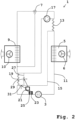
- FIG. 2 is an exemplary embodiment of one Heating and/or air conditioning system 1 with a refrigerant circuit 11 comprising a compressor 3, a condenser/gas cooler 5, an expansion element 7 designed as a thermostatic expansion valve and an evaporator 9, shown schematically.
- the air conveying device 6 is assigned to the condenser/gas cooler 5 and the air conveying device 10 is assigned to the evaporator 9.
- the refrigerant circuit 11 is operated transcritically or supercritically, for example with CO 2 as the refrigerant, so that the condenser/gas cooler 5 is designed as a gas cooler.
- a refrigerant circuit 11 that is operated in a subcritical manner is also conceivable.
- the first internal heat exchanger 13 is integrated between the condenser/gas cooler 5 and the expansion element 7. It is intended for heat exchange between the refrigerant of the refrigerant circuit 11 and the heat medium of the secondary circuit 15.
- the heat medium of the secondary circuit is water or a water-glycol mixture. Driven by the pump 17, the heat medium can circulate in the secondary circuit. It absorbs heat from the refrigerant in the first internal heat exchanger 13 downstream of the pump 17 and transports it towards the second internal heat exchanger 19.
- the first internal heat exchanger 13 and the second internal heat exchanger 19 are arranged relative to one another in such a way that they are thermally coupled or can be thermally coupled using the heat medium of the secondary circuit 15.
- the secondary circuit 15 has a bypass 27 for the second internal heat exchanger 19.
- the controllable valve 29 is arranged in this bypass 27.
- another controllable valve 31 is arranged in parallel in front of the internal heat exchanger 19 in the secondary circuit 15.
- the two valves 29 and 31 are connected via in Fig. 2 Control connections shown in dashed lines are automatically controlled by the controller 21. They are controlled in such a way that the volume flow portion of the heat medium in the secondary circuit 15, which flows through the bypass 27 and therefore not through the second internal heat exchanger 19, can be adjusted in size.
- the controller 21 receives the temperature value of the refrigerant from the temperature sensor 23 in the low-pressure area of the refrigerant circuit 11 in front of the compressor 3.
- the controller 21 receives the pressure value of the refrigerant from the pressure sensor 25 in the low pressure area of the refrigerant circuit 11 in front of the compressor 3.
- the controller 21 determines the actual value of the superheat of the refrigerant and compares this with a predetermined setpoint of the superheat of, for example, 10 ° K. Depending on whether the actual value of the superheat is above or below the setpoint, it regulates the control 21 uses the two valves 29 and 31 to increase or decrease the proportion of the volume flow of the heat medium through the bypass 27, so that the internal heat exchange via the first internal heat exchanger 13 and the second internal heat exchanger 19 is regulated down or up. In this exemplary embodiment, the pump performance of the pump 17 cannot be regulated.
- the heating and/or air conditioning system 1 is designed for heating and/or cooling air in the interior of a vehicle.
- FIG. 3 an exemplary embodiment of a heating and/or air conditioning system 1 with a secondary circuit 15, which is also designed as a heating circuit, is shown schematically.
- the compressor 3 condenser/gas cooler 5, first internal heat exchanger 13, the expansion element 7 designed as a thermostatic expansion valve, evaporator 9 and second internal heat exchanger 19, its refrigerant circuit 11 also includes a fluid-fluid heat exchanger 33.
- the condenser/gas cooler 5 is Air conveying device 6 and the evaporator 9 are assigned the air conveying device 10.
- One side of the fluid-fluid heat exchanger 33 is arranged in the high-pressure area between the compressor 3 and the condenser/gas cooler 5 in the refrigerant circuit 11.
- This fluid-fluid heat exchanger 33 is like the first internal heat exchanger 13 and the second internal heat exchanger 19 for heat exchange between refrigerant Refrigerant circuit 11 and heat medium of the secondary circuit 15 are provided.
- a bypass 37 which can be controlled with a valve 35, is arranged in the secondary circuit 15 for the fluid-fluid heat exchanger 33.
- the controller 21 controls via in Fig. 3
- the control connection shown in dashed lines automatically passes the controllable valve 35 and thus the proportion of the volume flow of the heat medium through the bypass 37 past the fluid-fluid heat exchanger 33.
- a further heat exchanger 39 which is designed as an air-fluid heat exchanger, is arranged in the secondary circuit 15 downstream of the fluid-fluid heat exchanger 33.
- the blower 41 is set up to convey air through the further heat exchanger 39 into the room or area to be heated. It is also conceivable that the further heat exchanger 39 is designed for direct heat exchange with an object to be heated, such as a traction battery.
- a bypass 45 which can be controlled with a valve 43, runs in the secondary circuit 15 to the further heat exchanger 39.
- the control 21 automatically controls the controllable valve 43 and thus the proportion of the volume flow of the heat medium through the bypass 45 past the further heat exchanger 39 via a control connection.
- the control 21 automatically controls the controllable valve 29 via a control connection and thus the proportion of the volume flow of the heat medium through the bypass 27 past the second internal heat exchanger 19.
- the heating medium is water or a water-glycol mixture.
- pump 17 When pump 17 is activated, which is in its Pump power can be regulated, the heat medium circulates in the secondary circuit 15. It absorbs heat from the refrigerant in the first internal heat exchanger 13 integrated between the capacitor 5 and the expansion element 7 in the high-pressure area of the refrigerant circuit 11. In the secondary circuit 15 further downstream, the heat medium absorbs additional heat from the refrigerant of the refrigerant circuit 11 in its volume flow proportion, which can be controlled via the valve 35 in the fluid-fluid heat exchanger 33.
- This heat absorbed in the fluid-fluid heat exchanger 33 is used for heating.
- a proportion of the volume flow of the heat medium which can be controlled via the valve 43, gives off heat to the further heat exchanger 39 in this heat for heating to the medium air conveyed by the fan 41.
- the first internal heat exchanger 13 and the second internal heat exchanger 19 are arranged relative to one another in such a way that they can be thermally coupled using the heat medium of the secondary circuit 15.
- the controller 21 receives the temperature value and the pressure value of the refrigerant there in the high-pressure range from the temperature sensor 23 and pressure sensor 25 arranged in the refrigerant circuit 11 in front of the expansion element 7. Furthermore, the controller 21 receives information about how much heating is required. From this information, the controller 21 automatically determines how the pump 17 and the valves 35, 43 and 29 are to be regulated and regulates them accordingly.
- the heating and/or air conditioning system 1 is designed for heating and/or cooling air in an interior of a vehicle, such as the passenger compartment of a rail vehicle.
- FIG. 4 an exemplary embodiment of a heating and/or air conditioning system 1 with a secondary circuit 15, which is also designed as a cooling circuit, is shown schematically. Except for the arrangement of the fluid-fluid heat exchanger 33, the bypass 37 that can be controlled with valve 35, the further heat exchanger 39 with fan 41 and the bypass 45 that can be controlled with valve 43, it corresponds to that in Fig. 3 Shown heating and/or air conditioning system 1. It therefore includes how to Fig.
- the fluid-fluid heat exchanger 33 is intended for heat exchange between the refrigerant of the refrigerant circuit 11 and the heat medium of the secondary circuit 15. In secondary circuit 15 it is closed
- the fluid-fluid heat exchanger 33 has a bypass 37 that can be controlled with a valve 35.
- a further heat exchanger 39 which is designed as an air-fluid heat exchanger, is arranged in the secondary circuit 15 downstream of the fluid-fluid heat exchanger 33. It is used to exchange heat with a medium, for example air for the interior of a vehicle.
- the blower 41 is set up to convey air through the further heat exchanger 39 into the room or area to be cooled. It is also conceivable that the further heat exchanger 39 is designed for direct heat exchange with an object to be cooled, such as a traction battery.
- a bypass 45 which can be controlled with a valve 43, runs in the secondary circuit 15 to the further heat exchanger 39.
- the heating medium is water or a water-glycol mixture.
- the heat medium circulates in the secondary circuit 15. It absorbs heat from the refrigerant in the first internal heat exchanger 13.
- the heat medium releases additional heat to the refrigerant of the refrigerant circuit 11 in its volume flow proportion, which can be controlled via the valve 35 in the fluid-fluid heat exchanger 33.
- the heat medium cooled down in this way is used for cooling.
- a portion of the volume flow of the heat medium that can be controlled via the valve 43 takes place to the further heat exchanger 39 in this heat for cooling the air conveyed by the fan 41.
- the controller 21 receives the temperature value and the pressure value of the refrigerant there in the high-pressure range from the temperature sensor 23 and pressure sensor 25 arranged in the refrigerant circuit 11 in front of the expansion element 7. Furthermore, the controller 21 receives information about how much cooling is required. From this information, the controller 21 automatically determines how the pump 17 and the valves 35, 43 and 29 are to be regulated and regulates these via the in Fig. 4 Control connections shown in dashed lines accordingly.
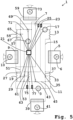
- a further exemplary embodiment of a heating and/or air conditioning system 1 is shown schematically. It comprises a refrigerant circuit 11, a secondary circuit 15 which is also designed as a heating circuit and a further secondary circuit 51 which is also designed as a cooling circuit, the third internal heat exchanger 53 being provided for heat exchange between the heat medium of the secondary circuit 15 and the further heat medium of the further secondary circuit 51.
- the compressor 3 In the refrigerant circuit 11, in the flow direction of the refrigerant, are the compressor 3, the fluid-fluid heat exchanger 33, the condenser/gas cooler 5, and the first internal heat exchanger 13, the expansion element 7 designed as a thermostatic expansion valve, the further fluid-fluid heat exchanger 55, the evaporator 9 and the second internal heat exchanger 19 are arranged.
- the refrigerant is, for example, CO 2 .
- the air conveying device 6 is assigned to the condenser/gas cooler 5 and the air conveying device 10 is assigned to the evaporator 9.
- the heat medium which is water or a water-glycol mixture
- the heat medium can be passed successively through the first internal heat exchanger 13, the fluid-fluid heat exchanger 33, the further heat exchanger 39 and the third internal one in the secondary circuit 15
- Pump heat exchanger 53 whereby instead of through the fluid-fluid heat exchanger 33, a portion of the volume flow of the heat medium that can be regulated in size with valve 35 can flow through the bypass 37 and instead of through the further heat exchanger 39, a portion that can be regulated in size with valve 43 can flow Volume flow of the heat medium can flow through the bypass 45.
- the fan 41 assigned to the further heat exchanger 39 conveys air as a medium into the room to be heated.
- the first internal heat exchanger 15 is thermally coupled to the third internal heat exchanger 53 via the heat medium in the secondary circuit 15. Via the heat exchange in the third internal heat exchanger 53, a thermal coupling with the further heat medium, which is water or a water-glycol mixture, of the further secondary circuit 51 is provided. During operation, the further heat medium circulates in the further secondary circuit 51, driven by a pump 57 whose pumping capacity can be regulated.
- the further heat medium which is water or a water-glycol mixture
- each of these heat exchangers in the further secondary circuit 51 having a bypass 27, 63, 67, 71 which can be controlled with a valve 29, 61, 65, 69 and instead of through the respective one Heat exchangers 19, 53, 55, 59 can flow through the respective bypass 27, 63, 67, 71, a portion of the volume flow of the further heat medium that can be regulated in size with the respective valve 29, 61, 65, 69.
- the fan 73 assigned to the further heat exchanger 59 conveys air as a medium into the room to be cooled.
- Second internal heat exchanger 19 flows via the heat medium of the secondary circuit 15, the third internal heat exchanger 53 and further via the further heat medium of the further secondary circuit 51.
- the first internal heat exchanger 13 and the second internal heat exchanger 19 are thus arranged in such a way that they can be used under other things, the heat medium of the secondary circuit 15 are thermally coupled or can be thermally coupled.
- the controller 21 receives from the temperature sensor 23 and pressure sensor 25 arranged in the high-pressure area of the refrigerant circuit 11 in front of the expansion element 7 and from the temperature sensor 75 and arranged in the low-pressure area of the refrigerant circuit 11 in front of the compressor 3 Pressure sensor 77 the temperature values and pressure values of the refrigerant in the respective area. Furthermore, the controller 21 receives information about how much cooling or heating is required. From this information, the controller 21 automatically determines how the pumps 17 and 57 as well as the valves 29, 35, 43, 61, 65 and 69 are to be regulated and regulates these via the in Fig. 5 Control connections shown in dashed lines accordingly.
- the heating and/or air conditioning system 1 is designed for heating and/or cooling air in an interior of a vehicle, such as a passenger compartment of a bus.
- a vehicle such as a passenger compartment of a bus.
- it can be designed as a rooftop system.
- FIG. 6 an exemplary embodiment of a vehicle 81 with a heating and/or air conditioning system 1 according to the invention is shown.
- the vehicle 81 is designed as a bus.
- the heating and/or air conditioning system 1 is mounted on the vehicle 81 as a roof-mounted system.
- she is one of the in Fig. 1 , 2 , 3 , 4 and 5 shown heating and / or air conditioning systems 1 and for heating and / or cooling air for the interior 83 of the vehicle 81 as set up in particular for the passenger compartment.
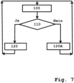
- FIG. 7 An exemplary embodiment of a method according to the invention is shown in a flowchart representation. It is a method for controlling a heating and/or air conditioning system according to the invention, such as that in Fig. 5 shown.
- step a pressure values in the refrigerant circuit with the corresponding pressure sensors and temperature values in the refrigerant circuit with the corresponding temperature sensors are determined by measurement.
- step aa it is determined based on the pressure values and temperature values determined in the first step 100 whether there is excessive overheating of the refrigerant upstream of the compressor and/or excessive undercooling of the refrigerant upstream of the expansion element /present.
- the boiling temperature of the refrigerant such as CO 2 , is determined for the respective measured pressure value. This is done using the function of the boiling temperature depending on the pressure according to the vapor pressure curve in the pressure-temperature relationship.
- a fictitious boiling temperature can be assumed for the measured pressure value.
- the temperature value of the refrigerant measured in the same area in the refrigerant circuit as the respective pressure value is compared with the boiling temperature or fictitious boiling temperature for the respective measured pressure value.
- the difference between the boiling temperature or fictitious boiling temperature minus the measured temperature value is formed.
- the difference is formed between the measured temperature value minus the boiling temperature.
- step 110 If the subcooling of the refrigerant in the area of the refrigerant circuit in front of the expansion element is above a threshold value specified for excessive subcooling For example, 20 °K, then in step 110 too much supercooling is assumed and otherwise not. The result of the determination is therefore affirmative if the hypothermia is greater than the threshold value. The same applies when determining whether the refrigerant is overheating too much in the area in front of the compressor. The determination is to be made in the affirmative if the overheating is greater than a predetermined threshold value of, for example, 15 °K.
- step 110 If either of the two determinations in step 110 is affirmative, the overall result in step 110 is “ yes. ” Then in step 120 the pump of the secondary circuit is deactivated or remains deactivated or there is at least one valve of a bypass according to claim 2 in the secondary circuit or, if the heating and / or air conditioning system includes the further secondary circuit, at least one valve of a bypass according to claim 2 or 4 in the further secondary circuit opens or remains open with respect to the bypass. This means that the internal heat exchange via the first and second internal heat exchangers is interrupted.
- step 110 If no determination is made in the affirmative in step 110, the overall result in step 110 is “ No ” . Then in step 120A the pump of the secondary circuit is activated or remains activated and, if present, every valve of a bypass according to claim 2 in the secondary circuit and, if the heating and / or air conditioning system includes the further secondary circuit, if present every valve of a bypass according to claim 2 and 4 are closed or remain closed with regard to the bypass.
- the method begins again after steps 120 or 120A after a predetermined period of time, for example 0.1 seconds.
- step 100 the temperature value of the refrigerant after the compressor is additionally determined using a temperature sensor in the high-pressure area of the refrigerant circuit downstream of the compressor.
- this measured temperature value is then compared with a predetermined threshold value of, for example, 150 ° C with, for example, the refrigerant CO 2 . If the threshold value is exceeded, the determination as to whether the temperature of the refrigerant downstream of the compressor is too high is answered in the affirmative and continues with step 120. Otherwise, if no determination is made in the affirmative in step 110, i.e. "No", the process continues with step 120A.
- Fig. 8 is a flowchart representation of a further exemplary embodiment of a method according to the invention for controlling a heating and / or air conditioning system according to the invention, such as that in Fig. 3 shown.
- a pressure value in the refrigerant circuit is determined with a pressure sensor in the high-pressure area between the compressor and expansion element and a temperature value of the refrigerant is determined with a temperature sensor in the high-pressure area of the refrigerant circuit in front of the expansion element.
- an actual value regarding subcooling of the refrigerant in the high-pressure region of the refrigerant circuit in front of the expansion element is determined based on the pressure value and temperature value determined in the first step 200.
- This determined actual value is the subcooling in °K.
- the determination is made to determine whether the actual value is greater or less than a setpoint of subcooling of, for example, 15 °K, and, depending on the result, a decision is made as to which step follows.
- step 230 follows, in which, the higher this difference is, the more the pumping power of the pump in the secondary circuit is increased and, if present, each valve of a bypass according to claim 2 in the secondary circuit and, provided that the heating and/or air conditioning system comprises the further secondary circuit, if present, each valve of a bypass according to claims 2 and 4 is further narrowed with respect to the bypass or remains closed. This means that the internal heat exchange via the first and second internal heat exchangers is increased more or less or remains at the maximum position depending on the size of the difference determined.
- step 220 is followed by step 230A, in which, the higher the difference, the more the pumping power of the secondary circuit pump is reduced and, if present, at least one Valve of a bypass according to claim 2 in the secondary circuit and / or, if the heating and / or air conditioning system is further Secondary circuit includes, if present, at least one valve of a bypass according to claim 2 or 4 with respect to the bypass, the further it is opened or remains completely open. This means that the internal heat exchange via the first and second internal heat exchangers is reduced to a greater or lesser extent or remains unchanged, depending on the size of the difference determined.
- the method begins again after steps 230 or 230A after a predetermined period of time, for example 0.1 seconds.
- the method counteracts a deviation of the subcooling from a specified target value at which the heating and/or air conditioning system runs particularly efficiently.
- Fig. 9 is a flowchart representation of a further exemplary embodiment of a method according to the invention for controlling a heating and / or air conditioning system according to the invention, such as that in Fig. 5 shown.
- a pressure value in the refrigerant circuit is determined with a pressure sensor in the low-pressure area between the expansion element and the compressor and a temperature value of the refrigerant is determined with a temperature sensor in the low-pressure area of the refrigerant circuit in front of the compressor.
- an actual value regarding overheating of the refrigerant in the low-pressure region of the refrigerant circuit in front of the compressor is determined based on the pressure value and temperature value determined in the first step 300.
- This determined actual value is the actual superheat in °K.
- step 320 is determined based on the determination of whether the actual value is greater or less than a setpoint of superheating of, for example, 8 °K, and, depending on the result, a decision is made as to which step follows.
- step 330 follows, in which, the higher this difference is, the more the pumping power of the pump in the secondary circuit is increased and, if present, each valve of a bypass according to claim 2 in the secondary circuit and, if the heating - and / or air conditioning includes the further secondary circuit, if present, each valve of a bypass according to claims 2 and 4 is narrowed further with respect to the bypass or remains closed.
- step 320 is followed by step 330A, in which, the higher the difference, the more the pumping power of the secondary circuit pump is reduced and, if present, at least one valve a bypass according to claim 2 in the secondary circuit and / or, if the heating and / or air conditioning system includes the further secondary circuit, if present at least one valve of a bypass according to claim 2 or 4 is opened the further with respect to the bypass or remains completely open.
- the method begins again after steps 330 or 330A after a predetermined period of time, for example 0.1 seconds.
- the method is used to determine a deviation in superheating from a specified setpoint the heating and/or air conditioning system runs particularly efficiently.
Landscapes
- Engineering & Computer Science (AREA)
- Mechanical Engineering (AREA)
- Physics & Mathematics (AREA)
- Thermal Sciences (AREA)
- General Engineering & Computer Science (AREA)
- Compression-Type Refrigeration Machines With Reversible Cycles (AREA)
- Air-Conditioning For Vehicles (AREA)
Priority Applications (3)
| Application Number | Priority Date | Filing Date | Title |
|---|---|---|---|
| PL19182073.7T PL3756916T3 (pl) | 2019-06-24 | 2019-06-24 | Układ ogrzewania i/lub klimatyzacji z wewnętrznymi wymiennikami ciepła |
| EP19182073.7A EP3756916B1 (de) | 2019-06-24 | 2019-06-24 | Heiz- und/oder klimaanlage mit internen wärmetauschern |
| CN202010586194.3A CN112129001B (zh) | 2019-06-24 | 2020-06-24 | 具有内部换热器的加热和/或空调设施 |
Applications Claiming Priority (1)
| Application Number | Priority Date | Filing Date | Title |
|---|---|---|---|
| EP19182073.7A EP3756916B1 (de) | 2019-06-24 | 2019-06-24 | Heiz- und/oder klimaanlage mit internen wärmetauschern |
Publications (3)
| Publication Number | Publication Date |
|---|---|
| EP3756916A1 EP3756916A1 (de) | 2020-12-30 |
| EP3756916B1 true EP3756916B1 (de) | 2023-09-27 |
| EP3756916C0 EP3756916C0 (de) | 2023-09-27 |
Family
ID=67003319
Family Applications (1)
| Application Number | Title | Priority Date | Filing Date |
|---|---|---|---|
| EP19182073.7A Active EP3756916B1 (de) | 2019-06-24 | 2019-06-24 | Heiz- und/oder klimaanlage mit internen wärmetauschern |
Country Status (3)
| Country | Link |
|---|---|
| EP (1) | EP3756916B1 (pl) |
| CN (1) | CN112129001B (pl) |
| PL (1) | PL3756916T3 (pl) |
Families Citing this family (2)
| Publication number | Priority date | Publication date | Assignee | Title |
|---|---|---|---|---|
| DE102023206969A1 (de) * | 2023-07-21 | 2025-01-23 | Siemens Energy Global GmbH & Co. KG | Wärmepumpenanordnung und Verfahren zum Betreiben einer Wärmepumpenanordnung |
| DE102024124253A1 (de) | 2024-08-26 | 2026-02-26 | Audi Aktiengesellschaft | Kälteanlage mit Wärmepumpenfunktion für ein Kraftfahrzeug mit hochdruckseitig stromabwärts von einem inneren Wärmeübertrager angeordneter Sensorvorrichtung sowie Verfahren zum Betreiben einer solchen Kälteanlage |
Family Cites Families (14)
| Publication number | Priority date | Publication date | Assignee | Title |
|---|---|---|---|---|
| DE10247667A1 (de) | 2001-10-15 | 2003-04-17 | Luk Fahrzeug Hydraulik | Klimaanlage |
| JP4731806B2 (ja) * | 2003-12-01 | 2011-07-27 | パナソニック株式会社 | 冷凍サイクル装置およびその制御方法 |
| DE602004005588T2 (de) | 2004-08-04 | 2007-12-13 | Delphi Technologies, Inc., Troy | Heizungs-, Lüftungs-, Klimatisierungssystem |
| DE102005005430A1 (de) | 2005-02-05 | 2006-08-10 | Daimlerchrysler Ag | Verfahren zum Betreiben einer Klimaanlage |
| SE534348C2 (sv) * | 2008-10-07 | 2011-07-19 | Scania Cv Abp | System och anordning innefattande en sammanbyggd kondensor och förångare |
| EP2420746B8 (en) * | 2009-04-13 | 2016-04-06 | Panasonic Intellectual Property Management Co., Ltd. | Heat pump heating system |
| JP5270523B2 (ja) * | 2009-12-04 | 2013-08-21 | シャープ株式会社 | 冷凍冷蔵庫 |
| WO2013160929A1 (ja) * | 2012-04-23 | 2013-10-31 | 三菱電機株式会社 | 冷凍サイクルシステム |
| KR101714459B1 (ko) | 2013-08-22 | 2017-03-10 | 한온시스템 주식회사 | 차량용 히트 펌프 시스템 |
| WO2016059837A1 (ja) * | 2014-10-16 | 2016-04-21 | サンデンホールディングス株式会社 | ヒートポンプ式暖房装置 |
| FR3030700B1 (fr) | 2014-12-18 | 2019-03-22 | Valeo Systemes Thermiques | Circuit de climatisation de vehicule automobile |
| FR3033394B1 (fr) | 2015-03-04 | 2017-02-17 | Valeo Systemes Thermiques | Circuit de gestion thermique |
| FR3055250B1 (fr) | 2016-08-30 | 2018-08-10 | Valeo Systemes Thermiques | Circuit de climatisation inversible indirect de vehicule automobile et procede de fonctionnement correspondant |
| FR3061867B1 (fr) | 2017-01-17 | 2020-05-01 | Valeo Systemes Thermiques | Boucle de circulation d'un fluide refrigerant pour le conditionnement d'air d'habitacle d'un vehicule |
-
2019
- 2019-06-24 EP EP19182073.7A patent/EP3756916B1/de active Active
- 2019-06-24 PL PL19182073.7T patent/PL3756916T3/pl unknown
-
2020
- 2020-06-24 CN CN202010586194.3A patent/CN112129001B/zh active Active
Also Published As
| Publication number | Publication date |
|---|---|
| CN112129001A (zh) | 2020-12-25 |
| PL3756916T3 (pl) | 2024-02-12 |
| EP3756916A1 (de) | 2020-12-30 |
| EP3756916C0 (de) | 2023-09-27 |
| CN112129001B (zh) | 2023-03-10 |
Similar Documents
| Publication | Publication Date | Title |
|---|---|---|
| EP3697635B1 (de) | Verfahren zum betreiben eines kältemittelkreislaufs sowie fahrzeugkälteanlage | |
| DE112020004318T5 (de) | Anschlussmodul | |
| EP1467879B1 (de) | Heiz-/kühlkreislauf für eine klimaanlage eines kraftfahrzeugs, klimaanlage und verfahren zur steuerung derselben | |
| DE102009056027B4 (de) | Fahrzeug, insbesondere Elektrofahrzeug | |
| EP3833562B1 (de) | Verfahren zum betreiben einer kälteanlage für ein fahrzeug mit einem eine wärmepumpenfunktion aufweisenden kältemittelkreislauf | |
| EP3444542B1 (de) | Kreislaufsystem für ein fahrzeug und verfahren dazu | |
| DE102014203895B4 (de) | Kälteanlage | |
| DE102010051976B4 (de) | Klimaanlage für ein Kraftfahrzeug | |
| DE112016002423B4 (de) | Fahrzeugklimaanlage | |
| DE112017003010T5 (de) | Kältekreislaufvorrichtung | |
| DE102012222594B4 (de) | Verfahren zum Betreiben eines Kältemittelkreislaufs als Wärmepumpe sowie als Wärmepumpe betreibbarer Kältemittelkreislauf | |
| AT522875B1 (de) | Verfahren zur Regelung eines Expansionsventils | |
| DE102018201945B4 (de) | Verfahren zum Betreiben eines Kältemittelkreislaufs sowie Fahrzeugkälteanlage | |
| EP1472106B1 (de) | Klimaanlage mit heizfunktion und verfahren zum betrieb einer klimaanlagen mit heizfunktion | |
| DE102018113687B4 (de) | Vorrichtung und Verfahren zur Kühlung von Batteriezellenmodulen | |
| DE10036038A1 (de) | Klimaanlage eines Kraftfahrzeuges | |
| WO2009146856A1 (de) | Klimaanlage zur konditionierung mehrerer fluide | |
| DE112018003315T5 (de) | Luftkonditioniereinrichtung | |
| DE102018207049B4 (de) | Kälteanlage für ein Fahrzeug mit einem eine Wärmepumpenfunktion aufweisenden Kältemittelkreislauf | |
| WO2023280507A1 (de) | Kältekreislauf sowie wärmemanagementsystem und kraftfahrzeug mit einem solchen | |
| DE112021003660T5 (de) | Kältekreisvorrichtung | |
| EP1462281B1 (de) | Klimaanlage mit mehreren Verdampfern für ein Kraftfahrzeug | |
| DE112022004548T5 (de) | Wärmepumpenkreislaufvorrichtung | |
| EP3756916B1 (de) | Heiz- und/oder klimaanlage mit internen wärmetauschern | |
| DE102017208231B4 (de) | Kälteanlage für ein Fahrzeug mit einem Kältemittelkreislauf |
Legal Events
| Date | Code | Title | Description |
|---|---|---|---|
| PUAI | Public reference made under article 153(3) epc to a published international application that has entered the european phase |
Free format text: ORIGINAL CODE: 0009012 |
|
| STAA | Information on the status of an ep patent application or granted ep patent |
Free format text: STATUS: REQUEST FOR EXAMINATION WAS MADE |
|
| 17P | Request for examination filed |
Effective date: 20200915 |
|
| AK | Designated contracting states |
Kind code of ref document: A1 Designated state(s): AL AT BE BG CH CY CZ DE DK EE ES FI FR GB GR HR HU IE IS IT LI LT LU LV MC MK MT NL NO PL PT RO RS SE SI SK SM TR |
|
| AX | Request for extension of the european patent |
Extension state: BA ME |
|
| STAA | Information on the status of an ep patent application or granted ep patent |
Free format text: STATUS: EXAMINATION IS IN PROGRESS |
|
| 17Q | First examination report despatched |
Effective date: 20210225 |
|
| GRAP | Despatch of communication of intention to grant a patent |
Free format text: ORIGINAL CODE: EPIDOSNIGR1 |
|
| STAA | Information on the status of an ep patent application or granted ep patent |
Free format text: STATUS: GRANT OF PATENT IS INTENDED |
|
| RIC1 | Information provided on ipc code assigned before grant |
Ipc: B60H 1/00 20060101ALN20230315BHEP Ipc: F25B 49/02 20060101ALI20230315BHEP Ipc: F25B 6/04 20060101ALI20230315BHEP Ipc: F25B 5/04 20060101ALI20230315BHEP Ipc: F25B 25/00 20060101ALI20230315BHEP Ipc: F25B 40/00 20060101ALI20230315BHEP Ipc: B60H 1/32 20060101AFI20230315BHEP |
|
| RIC1 | Information provided on ipc code assigned before grant |
Ipc: B60H 1/00 20060101ALN20230321BHEP Ipc: F25B 49/02 20060101ALI20230321BHEP Ipc: F25B 6/04 20060101ALI20230321BHEP Ipc: F25B 5/04 20060101ALI20230321BHEP Ipc: F25B 25/00 20060101ALI20230321BHEP Ipc: F25B 40/00 20060101ALI20230321BHEP Ipc: B60H 1/32 20060101AFI20230321BHEP |
|
| INTG | Intention to grant announced |
Effective date: 20230414 |
|
| RIC1 | Information provided on ipc code assigned before grant |
Ipc: B60H 1/00 20060101ALN20230403BHEP Ipc: F25B 49/02 20060101ALI20230403BHEP Ipc: F25B 6/04 20060101ALI20230403BHEP Ipc: F25B 5/04 20060101ALI20230403BHEP Ipc: F25B 25/00 20060101ALI20230403BHEP Ipc: F25B 40/00 20060101ALI20230403BHEP Ipc: B60H 1/32 20060101AFI20230403BHEP |
|
| GRAJ | Information related to disapproval of communication of intention to grant by the applicant or resumption of examination proceedings by the epo deleted |
Free format text: ORIGINAL CODE: EPIDOSDIGR1 |
|
| STAA | Information on the status of an ep patent application or granted ep patent |
Free format text: STATUS: EXAMINATION IS IN PROGRESS |
|
| GRAP | Despatch of communication of intention to grant a patent |
Free format text: ORIGINAL CODE: EPIDOSNIGR1 |
|
| STAA | Information on the status of an ep patent application or granted ep patent |
Free format text: STATUS: GRANT OF PATENT IS INTENDED |
|
| INTG | Intention to grant announced |
Effective date: 20230721 |
|
| RIC1 | Information provided on ipc code assigned before grant |
Ipc: B60H 1/00 20060101ALN20230710BHEP Ipc: F25B 49/02 20060101ALI20230710BHEP Ipc: F25B 6/04 20060101ALI20230710BHEP Ipc: F25B 5/04 20060101ALI20230710BHEP Ipc: F25B 25/00 20060101ALI20230710BHEP Ipc: F25B 40/00 20060101ALI20230710BHEP Ipc: B60H 1/32 20060101AFI20230710BHEP |
|
| GRAS | Grant fee paid |
Free format text: ORIGINAL CODE: EPIDOSNIGR3 |
|
| GRAA | (expected) grant |
Free format text: ORIGINAL CODE: 0009210 |
|
| STAA | Information on the status of an ep patent application or granted ep patent |
Free format text: STATUS: THE PATENT HAS BEEN GRANTED |
|
| AK | Designated contracting states |
Kind code of ref document: B1 Designated state(s): AL AT BE BG CH CY CZ DE DK EE ES FI FR GB GR HR HU IE IS IT LI LT LU LV MC MK MT NL NO PL PT RO RS SE SI SK SM TR |
|
| REG | Reference to a national code |
Ref country code: GB Ref legal event code: FG4D Free format text: NOT ENGLISH |
|
| REG | Reference to a national code |
Ref country code: CH Ref legal event code: EP |
|
| REG | Reference to a national code |
Ref country code: DE Ref legal event code: R096 Ref document number: 502019009463 Country of ref document: DE |
|
| REG | Reference to a national code |
Ref country code: IE Ref legal event code: FG4D Free format text: LANGUAGE OF EP DOCUMENT: GERMAN |
|
| U01 | Request for unitary effect filed |
Effective date: 20231012 |
|
| U07 | Unitary effect registered |
Designated state(s): AT BE BG DE DK EE FI FR IT LT LU LV MT NL PT SE SI Effective date: 20231023 |
|
| PG25 | Lapsed in a contracting state [announced via postgrant information from national office to epo] |
Ref country code: GR Free format text: LAPSE BECAUSE OF FAILURE TO SUBMIT A TRANSLATION OF THE DESCRIPTION OR TO PAY THE FEE WITHIN THE PRESCRIBED TIME-LIMIT Effective date: 20231228 |
|
| PG25 | Lapsed in a contracting state [announced via postgrant information from national office to epo] |
Ref country code: RS Free format text: LAPSE BECAUSE OF FAILURE TO SUBMIT A TRANSLATION OF THE DESCRIPTION OR TO PAY THE FEE WITHIN THE PRESCRIBED TIME-LIMIT Effective date: 20230927 Ref country code: NO Free format text: LAPSE BECAUSE OF FAILURE TO SUBMIT A TRANSLATION OF THE DESCRIPTION OR TO PAY THE FEE WITHIN THE PRESCRIBED TIME-LIMIT Effective date: 20231227 Ref country code: HR Free format text: LAPSE BECAUSE OF FAILURE TO SUBMIT A TRANSLATION OF THE DESCRIPTION OR TO PAY THE FEE WITHIN THE PRESCRIBED TIME-LIMIT Effective date: 20230927 Ref country code: GR Free format text: LAPSE BECAUSE OF FAILURE TO SUBMIT A TRANSLATION OF THE DESCRIPTION OR TO PAY THE FEE WITHIN THE PRESCRIBED TIME-LIMIT Effective date: 20231228 |
|
| PG25 | Lapsed in a contracting state [announced via postgrant information from national office to epo] |
Ref country code: IS Free format text: LAPSE BECAUSE OF FAILURE TO SUBMIT A TRANSLATION OF THE DESCRIPTION OR TO PAY THE FEE WITHIN THE PRESCRIBED TIME-LIMIT Effective date: 20240127 |
|
| PG25 | Lapsed in a contracting state [announced via postgrant information from national office to epo] |
Ref country code: ES Free format text: LAPSE BECAUSE OF FAILURE TO SUBMIT A TRANSLATION OF THE DESCRIPTION OR TO PAY THE FEE WITHIN THE PRESCRIBED TIME-LIMIT Effective date: 20230927 |
|
| PG25 | Lapsed in a contracting state [announced via postgrant information from national office to epo] |
Ref country code: SM Free format text: LAPSE BECAUSE OF FAILURE TO SUBMIT A TRANSLATION OF THE DESCRIPTION OR TO PAY THE FEE WITHIN THE PRESCRIBED TIME-LIMIT Effective date: 20230927 Ref country code: RO Free format text: LAPSE BECAUSE OF FAILURE TO SUBMIT A TRANSLATION OF THE DESCRIPTION OR TO PAY THE FEE WITHIN THE PRESCRIBED TIME-LIMIT Effective date: 20230927 Ref country code: IS Free format text: LAPSE BECAUSE OF FAILURE TO SUBMIT A TRANSLATION OF THE DESCRIPTION OR TO PAY THE FEE WITHIN THE PRESCRIBED TIME-LIMIT Effective date: 20240127 Ref country code: ES Free format text: LAPSE BECAUSE OF FAILURE TO SUBMIT A TRANSLATION OF THE DESCRIPTION OR TO PAY THE FEE WITHIN THE PRESCRIBED TIME-LIMIT Effective date: 20230927 Ref country code: CZ Free format text: LAPSE BECAUSE OF FAILURE TO SUBMIT A TRANSLATION OF THE DESCRIPTION OR TO PAY THE FEE WITHIN THE PRESCRIBED TIME-LIMIT Effective date: 20230927 Ref country code: SK Free format text: LAPSE BECAUSE OF FAILURE TO SUBMIT A TRANSLATION OF THE DESCRIPTION OR TO PAY THE FEE WITHIN THE PRESCRIBED TIME-LIMIT Effective date: 20230927 |
|
| U20 | Renewal fee for the european patent with unitary effect paid |
Year of fee payment: 6 Effective date: 20240423 |
|
| REG | Reference to a national code |
Ref country code: DE Ref legal event code: R097 Ref document number: 502019009463 Country of ref document: DE |
|
| PLBE | No opposition filed within time limit |
Free format text: ORIGINAL CODE: 0009261 |
|
| STAA | Information on the status of an ep patent application or granted ep patent |
Free format text: STATUS: NO OPPOSITION FILED WITHIN TIME LIMIT |
|
| 26N | No opposition filed |
Effective date: 20240628 |
|
| PG25 | Lapsed in a contracting state [announced via postgrant information from national office to epo] |
Ref country code: MC Free format text: LAPSE BECAUSE OF FAILURE TO SUBMIT A TRANSLATION OF THE DESCRIPTION OR TO PAY THE FEE WITHIN THE PRESCRIBED TIME-LIMIT Effective date: 20230927 |
|
| PG25 | Lapsed in a contracting state [announced via postgrant information from national office to epo] |
Ref country code: IE Free format text: LAPSE BECAUSE OF NON-PAYMENT OF DUE FEES Effective date: 20240624 |
|
| U20 | Renewal fee for the european patent with unitary effect paid |
Year of fee payment: 7 Effective date: 20250512 |
|
| PGFP | Annual fee paid to national office [announced via postgrant information from national office to epo] |
Ref country code: PL Payment date: 20250408 Year of fee payment: 7 |
|
| PGFP | Annual fee paid to national office [announced via postgrant information from national office to epo] |
Ref country code: GB Payment date: 20250611 Year of fee payment: 7 |
|
| PGFP | Annual fee paid to national office [announced via postgrant information from national office to epo] |
Ref country code: CH Payment date: 20250701 Year of fee payment: 7 |
|
| PG25 | Lapsed in a contracting state [announced via postgrant information from national office to epo] |
Ref country code: CY Free format text: LAPSE BECAUSE OF FAILURE TO SUBMIT A TRANSLATION OF THE DESCRIPTION OR TO PAY THE FEE WITHIN THE PRESCRIBED TIME-LIMIT; INVALID AB INITIO Effective date: 20190624 |
|
| PG25 | Lapsed in a contracting state [announced via postgrant information from national office to epo] |
Ref country code: HU Free format text: LAPSE BECAUSE OF FAILURE TO SUBMIT A TRANSLATION OF THE DESCRIPTION OR TO PAY THE FEE WITHIN THE PRESCRIBED TIME-LIMIT; INVALID AB INITIO Effective date: 20190624 |