EP3756916B1 - Heating and/or air conditioning system with internal heat exchangers - Google Patents
Heating and/or air conditioning system with internal heat exchangers Download PDFInfo
- Publication number
- EP3756916B1 EP3756916B1 EP19182073.7A EP19182073A EP3756916B1 EP 3756916 B1 EP3756916 B1 EP 3756916B1 EP 19182073 A EP19182073 A EP 19182073A EP 3756916 B1 EP3756916 B1 EP 3756916B1
- Authority
- EP
- European Patent Office
- Prior art keywords
- secondary circuit
- refrigerant
- bypass
- heating
- circuit
- Prior art date
- Legal status (The legal status is an assumption and is not a legal conclusion. Google has not performed a legal analysis and makes no representation as to the accuracy of the status listed.)
- Active
Links
- 238000010438 heat treatment Methods 0.000 title claims description 117
- 238000004378 air conditioning Methods 0.000 title claims description 98
- 239000003507 refrigerant Substances 0.000 claims description 234
- 230000001105 regulatory effect Effects 0.000 claims description 37
- 238000005086 pumping Methods 0.000 claims description 29
- 238000000034 method Methods 0.000 claims description 28
- 238000001816 cooling Methods 0.000 claims description 24
- 238000013021 overheating Methods 0.000 claims description 20
- 238000011144 upstream manufacturing Methods 0.000 claims description 20
- 239000000203 mixture Substances 0.000 claims description 9
- 238000012546 transfer Methods 0.000 claims description 9
- XLYOFNOQVPJJNP-UHFFFAOYSA-N water Substances O XLYOFNOQVPJJNP-UHFFFAOYSA-N 0.000 claims description 9
- 230000001276 controlling effect Effects 0.000 claims description 8
- 230000004913 activation Effects 0.000 claims description 7
- 230000009849 deactivation Effects 0.000 claims description 7
- 238000004781 supercooling Methods 0.000 claims description 6
- 239000012530 fluid Substances 0.000 description 29
- 238000009835 boiling Methods 0.000 description 11
- 238000011161 development Methods 0.000 description 9
- 230000018109 developmental process Effects 0.000 description 9
- 230000008901 benefit Effects 0.000 description 5
- 230000032258 transport Effects 0.000 description 5
- FXRLMCRCYDHQFW-UHFFFAOYSA-N 2,3,3,3-tetrafluoropropene Chemical compound FC(=C)C(F)(F)F FXRLMCRCYDHQFW-UHFFFAOYSA-N 0.000 description 2
- 230000008878 coupling Effects 0.000 description 2
- 238000010168 coupling process Methods 0.000 description 2
- 238000005859 coupling reaction Methods 0.000 description 2
- 238000010586 diagram Methods 0.000 description 2
- 230000008569 process Effects 0.000 description 2
- 239000003990 capacitor Substances 0.000 description 1
- 238000005516 engineering process Methods 0.000 description 1
- 230000002631 hypothermal effect Effects 0.000 description 1
- 239000000463 material Substances 0.000 description 1
- 238000005259 measurement Methods 0.000 description 1
Images


Classifications
-
- F—MECHANICAL ENGINEERING; LIGHTING; HEATING; WEAPONS; BLASTING
- F25—REFRIGERATION OR COOLING; COMBINED HEATING AND REFRIGERATION SYSTEMS; HEAT PUMP SYSTEMS; MANUFACTURE OR STORAGE OF ICE; LIQUEFACTION SOLIDIFICATION OF GASES
- F25B—REFRIGERATION MACHINES, PLANTS OR SYSTEMS; COMBINED HEATING AND REFRIGERATION SYSTEMS; HEAT PUMP SYSTEMS
- F25B1/00—Compression machines, plants or systems with non-reversible cycle
-
- B—PERFORMING OPERATIONS; TRANSPORTING
- B60—VEHICLES IN GENERAL
- B60H—ARRANGEMENTS OF HEATING, COOLING, VENTILATING OR OTHER AIR-TREATING DEVICES SPECIALLY ADAPTED FOR PASSENGER OR GOODS SPACES OF VEHICLES
- B60H1/00—Heating, cooling or ventilating [HVAC] devices
- B60H1/32—Cooling devices
- B60H1/3204—Cooling devices using compression
- B60H1/3228—Cooling devices using compression characterised by refrigerant circuit configurations
- B60H1/32284—Cooling devices using compression characterised by refrigerant circuit configurations comprising two or more secondary circuits, e.g. at evaporator and condenser side
-
- B—PERFORMING OPERATIONS; TRANSPORTING
- B60—VEHICLES IN GENERAL
- B60H—ARRANGEMENTS OF HEATING, COOLING, VENTILATING OR OTHER AIR-TREATING DEVICES SPECIALLY ADAPTED FOR PASSENGER OR GOODS SPACES OF VEHICLES
- B60H1/00—Heating, cooling or ventilating [HVAC] devices
- B60H1/00357—Air-conditioning arrangements specially adapted for particular vehicles
- B60H1/00371—Air-conditioning arrangements specially adapted for particular vehicles for vehicles carrying large numbers of passengers, e.g. buses
-
- B—PERFORMING OPERATIONS; TRANSPORTING
- B60—VEHICLES IN GENERAL
- B60H—ARRANGEMENTS OF HEATING, COOLING, VENTILATING OR OTHER AIR-TREATING DEVICES SPECIALLY ADAPTED FOR PASSENGER OR GOODS SPACES OF VEHICLES
- B60H1/00—Heating, cooling or ventilating [HVAC] devices
- B60H1/00642—Control systems or circuits; Control members or indication devices for heating, cooling or ventilating devices
- B60H1/00814—Control systems or circuits characterised by their output, for controlling particular components of the heating, cooling or ventilating installation
- B60H1/00878—Control systems or circuits characterised by their output, for controlling particular components of the heating, cooling or ventilating installation the components being temperature regulating devices
-
- B—PERFORMING OPERATIONS; TRANSPORTING
- B61—RAILWAYS
- B61D—BODY DETAILS OR KINDS OF RAILWAY VEHICLES
- B61D27/00—Heating, cooling, ventilating, or air-conditioning
- B61D27/0018—Air-conditioning means, i.e. combining at least two of the following ways of treating or supplying air, namely heating, cooling or ventilating
-
- F—MECHANICAL ENGINEERING; LIGHTING; HEATING; WEAPONS; BLASTING
- F25—REFRIGERATION OR COOLING; COMBINED HEATING AND REFRIGERATION SYSTEMS; HEAT PUMP SYSTEMS; MANUFACTURE OR STORAGE OF ICE; LIQUEFACTION SOLIDIFICATION OF GASES
- F25B—REFRIGERATION MACHINES, PLANTS OR SYSTEMS; COMBINED HEATING AND REFRIGERATION SYSTEMS; HEAT PUMP SYSTEMS
- F25B40/00—Subcoolers, desuperheaters or superheaters
-
- F—MECHANICAL ENGINEERING; LIGHTING; HEATING; WEAPONS; BLASTING
- F25—REFRIGERATION OR COOLING; COMBINED HEATING AND REFRIGERATION SYSTEMS; HEAT PUMP SYSTEMS; MANUFACTURE OR STORAGE OF ICE; LIQUEFACTION SOLIDIFICATION OF GASES
- F25B—REFRIGERATION MACHINES, PLANTS OR SYSTEMS; COMBINED HEATING AND REFRIGERATION SYSTEMS; HEAT PUMP SYSTEMS
- F25B49/00—Arrangement or mounting of control or safety devices
- F25B49/02—Arrangement or mounting of control or safety devices for compression type machines, plants or systems
-
- F—MECHANICAL ENGINEERING; LIGHTING; HEATING; WEAPONS; BLASTING
- F25—REFRIGERATION OR COOLING; COMBINED HEATING AND REFRIGERATION SYSTEMS; HEAT PUMP SYSTEMS; MANUFACTURE OR STORAGE OF ICE; LIQUEFACTION SOLIDIFICATION OF GASES
- F25B—REFRIGERATION MACHINES, PLANTS OR SYSTEMS; COMBINED HEATING AND REFRIGERATION SYSTEMS; HEAT PUMP SYSTEMS
- F25B5/00—Compression machines, plants or systems, with several evaporator circuits, e.g. for varying refrigerating capacity
- F25B5/04—Compression machines, plants or systems, with several evaporator circuits, e.g. for varying refrigerating capacity arranged in series
-
- F—MECHANICAL ENGINEERING; LIGHTING; HEATING; WEAPONS; BLASTING
- F25—REFRIGERATION OR COOLING; COMBINED HEATING AND REFRIGERATION SYSTEMS; HEAT PUMP SYSTEMS; MANUFACTURE OR STORAGE OF ICE; LIQUEFACTION SOLIDIFICATION OF GASES
- F25B—REFRIGERATION MACHINES, PLANTS OR SYSTEMS; COMBINED HEATING AND REFRIGERATION SYSTEMS; HEAT PUMP SYSTEMS
- F25B6/00—Compression machines, plants or systems, with several condenser circuits
- F25B6/04—Compression machines, plants or systems, with several condenser circuits arranged in series
-
- B—PERFORMING OPERATIONS; TRANSPORTING
- B60—VEHICLES IN GENERAL
- B60H—ARRANGEMENTS OF HEATING, COOLING, VENTILATING OR OTHER AIR-TREATING DEVICES SPECIALLY ADAPTED FOR PASSENGER OR GOODS SPACES OF VEHICLES
- B60H1/00—Heating, cooling or ventilating [HVAC] devices
- B60H1/00642—Control systems or circuits; Control members or indication devices for heating, cooling or ventilating devices
- B60H1/00814—Control systems or circuits characterised by their output, for controlling particular components of the heating, cooling or ventilating installation
- B60H1/00878—Control systems or circuits characterised by their output, for controlling particular components of the heating, cooling or ventilating installation the components being temperature regulating devices
- B60H2001/00949—Control systems or circuits characterised by their output, for controlling particular components of the heating, cooling or ventilating installation the components being temperature regulating devices comprising additional heating/cooling sources, e.g. second evaporator
-
- B—PERFORMING OPERATIONS; TRANSPORTING
- B60—VEHICLES IN GENERAL
- B60H—ARRANGEMENTS OF HEATING, COOLING, VENTILATING OR OTHER AIR-TREATING DEVICES SPECIALLY ADAPTED FOR PASSENGER OR GOODS SPACES OF VEHICLES
- B60H1/00—Heating, cooling or ventilating [HVAC] devices
- B60H1/00642—Control systems or circuits; Control members or indication devices for heating, cooling or ventilating devices
- B60H1/00814—Control systems or circuits characterised by their output, for controlling particular components of the heating, cooling or ventilating installation
- B60H1/00878—Control systems or circuits characterised by their output, for controlling particular components of the heating, cooling or ventilating installation the components being temperature regulating devices
- B60H2001/00957—Control systems or circuits characterised by their output, for controlling particular components of the heating, cooling or ventilating installation the components being temperature regulating devices comprising locations with heat exchange within the refrigerant circuit itself, e.g. cross-, counter-, or parallel heat exchange
-
- F—MECHANICAL ENGINEERING; LIGHTING; HEATING; WEAPONS; BLASTING
- F25—REFRIGERATION OR COOLING; COMBINED HEATING AND REFRIGERATION SYSTEMS; HEAT PUMP SYSTEMS; MANUFACTURE OR STORAGE OF ICE; LIQUEFACTION SOLIDIFICATION OF GASES
- F25B—REFRIGERATION MACHINES, PLANTS OR SYSTEMS; COMBINED HEATING AND REFRIGERATION SYSTEMS; HEAT PUMP SYSTEMS
- F25B2339/00—Details of evaporators; Details of condensers
- F25B2339/04—Details of condensers
- F25B2339/047—Water-cooled condensers
-
- F—MECHANICAL ENGINEERING; LIGHTING; HEATING; WEAPONS; BLASTING
- F25—REFRIGERATION OR COOLING; COMBINED HEATING AND REFRIGERATION SYSTEMS; HEAT PUMP SYSTEMS; MANUFACTURE OR STORAGE OF ICE; LIQUEFACTION SOLIDIFICATION OF GASES
- F25B—REFRIGERATION MACHINES, PLANTS OR SYSTEMS; COMBINED HEATING AND REFRIGERATION SYSTEMS; HEAT PUMP SYSTEMS
- F25B2400/00—General features or devices for refrigeration machines, plants or systems, combined heating and refrigeration systems or heat-pump systems, i.e. not limited to a particular subgroup of F25B
- F25B2400/04—Refrigeration circuit bypassing means
-
- F—MECHANICAL ENGINEERING; LIGHTING; HEATING; WEAPONS; BLASTING
- F25—REFRIGERATION OR COOLING; COMBINED HEATING AND REFRIGERATION SYSTEMS; HEAT PUMP SYSTEMS; MANUFACTURE OR STORAGE OF ICE; LIQUEFACTION SOLIDIFICATION OF GASES
- F25B—REFRIGERATION MACHINES, PLANTS OR SYSTEMS; COMBINED HEATING AND REFRIGERATION SYSTEMS; HEAT PUMP SYSTEMS
- F25B2400/00—General features or devices for refrigeration machines, plants or systems, combined heating and refrigeration systems or heat-pump systems, i.e. not limited to a particular subgroup of F25B
- F25B2400/05—Compression system with heat exchange between particular parts of the system
- F25B2400/054—Compression system with heat exchange between particular parts of the system between the suction tube of the compressor and another part of the cycle
-
- F—MECHANICAL ENGINEERING; LIGHTING; HEATING; WEAPONS; BLASTING
- F25—REFRIGERATION OR COOLING; COMBINED HEATING AND REFRIGERATION SYSTEMS; HEAT PUMP SYSTEMS; MANUFACTURE OR STORAGE OF ICE; LIQUEFACTION SOLIDIFICATION OF GASES
- F25B—REFRIGERATION MACHINES, PLANTS OR SYSTEMS; COMBINED HEATING AND REFRIGERATION SYSTEMS; HEAT PUMP SYSTEMS
- F25B25/00—Machines, plants or systems, using a combination of modes of operation covered by two or more of the groups F25B1/00 - F25B23/00
- F25B25/005—Machines, plants or systems, using a combination of modes of operation covered by two or more of the groups F25B1/00 - F25B23/00 using primary and secondary systems
-
- F—MECHANICAL ENGINEERING; LIGHTING; HEATING; WEAPONS; BLASTING
- F25—REFRIGERATION OR COOLING; COMBINED HEATING AND REFRIGERATION SYSTEMS; HEAT PUMP SYSTEMS; MANUFACTURE OR STORAGE OF ICE; LIQUEFACTION SOLIDIFICATION OF GASES
- F25B—REFRIGERATION MACHINES, PLANTS OR SYSTEMS; COMBINED HEATING AND REFRIGERATION SYSTEMS; HEAT PUMP SYSTEMS
- F25B2600/00—Control issues
- F25B2600/13—Pump speed control
-
- F—MECHANICAL ENGINEERING; LIGHTING; HEATING; WEAPONS; BLASTING
- F25—REFRIGERATION OR COOLING; COMBINED HEATING AND REFRIGERATION SYSTEMS; HEAT PUMP SYSTEMS; MANUFACTURE OR STORAGE OF ICE; LIQUEFACTION SOLIDIFICATION OF GASES
- F25B—REFRIGERATION MACHINES, PLANTS OR SYSTEMS; COMBINED HEATING AND REFRIGERATION SYSTEMS; HEAT PUMP SYSTEMS
- F25B2700/00—Sensing or detecting of parameters; Sensors therefor
- F25B2700/19—Pressures
- F25B2700/193—Pressures of the compressor
- F25B2700/1933—Suction pressures
-
- F—MECHANICAL ENGINEERING; LIGHTING; HEATING; WEAPONS; BLASTING
- F25—REFRIGERATION OR COOLING; COMBINED HEATING AND REFRIGERATION SYSTEMS; HEAT PUMP SYSTEMS; MANUFACTURE OR STORAGE OF ICE; LIQUEFACTION SOLIDIFICATION OF GASES
- F25B—REFRIGERATION MACHINES, PLANTS OR SYSTEMS; COMBINED HEATING AND REFRIGERATION SYSTEMS; HEAT PUMP SYSTEMS
- F25B2700/00—Sensing or detecting of parameters; Sensors therefor
- F25B2700/19—Pressures
- F25B2700/195—Pressures of the condenser
-
- F—MECHANICAL ENGINEERING; LIGHTING; HEATING; WEAPONS; BLASTING
- F25—REFRIGERATION OR COOLING; COMBINED HEATING AND REFRIGERATION SYSTEMS; HEAT PUMP SYSTEMS; MANUFACTURE OR STORAGE OF ICE; LIQUEFACTION SOLIDIFICATION OF GASES
- F25B—REFRIGERATION MACHINES, PLANTS OR SYSTEMS; COMBINED HEATING AND REFRIGERATION SYSTEMS; HEAT PUMP SYSTEMS
- F25B2700/00—Sensing or detecting of parameters; Sensors therefor
- F25B2700/21—Temperatures
- F25B2700/2115—Temperatures of a compressor or the drive means therefor
- F25B2700/21151—Temperatures of a compressor or the drive means therefor at the suction side of the compressor
-
- F—MECHANICAL ENGINEERING; LIGHTING; HEATING; WEAPONS; BLASTING
- F25—REFRIGERATION OR COOLING; COMBINED HEATING AND REFRIGERATION SYSTEMS; HEAT PUMP SYSTEMS; MANUFACTURE OR STORAGE OF ICE; LIQUEFACTION SOLIDIFICATION OF GASES
- F25B—REFRIGERATION MACHINES, PLANTS OR SYSTEMS; COMBINED HEATING AND REFRIGERATION SYSTEMS; HEAT PUMP SYSTEMS
- F25B2700/00—Sensing or detecting of parameters; Sensors therefor
- F25B2700/21—Temperatures
- F25B2700/2116—Temperatures of a condenser
- F25B2700/21163—Temperatures of a condenser of the refrigerant at the outlet of the condenser
-
- Y—GENERAL TAGGING OF NEW TECHNOLOGICAL DEVELOPMENTS; GENERAL TAGGING OF CROSS-SECTIONAL TECHNOLOGIES SPANNING OVER SEVERAL SECTIONS OF THE IPC; TECHNICAL SUBJECTS COVERED BY FORMER USPC CROSS-REFERENCE ART COLLECTIONS [XRACs] AND DIGESTS
- Y02—TECHNOLOGIES OR APPLICATIONS FOR MITIGATION OR ADAPTATION AGAINST CLIMATE CHANGE
- Y02T—CLIMATE CHANGE MITIGATION TECHNOLOGIES RELATED TO TRANSPORTATION
- Y02T30/00—Transportation of goods or passengers via railways, e.g. energy recovery or reducing air resistance
Definitions
- the invention relates to a heating and/or air conditioning system with a refrigerant circuit comprising at least one compressor, a condenser/gas cooler, an expansion element and an evaporator, and with at least one secondary circuit comprising at least one pump for a heat medium.
- the invention further relates to a vehicle, such as in particular a bus or rail vehicle, with such a heating and/or air conditioning system and to a method for controlling such a heating and/or air conditioning system.
- refrigerant such as CO 2
- refrigerant circuit During operation, refrigerant, such as CO 2 , circulates in a refrigerant circuit. It is compressed by the compressor and thereby heated and reaches the condenser/gas cooler via the refrigerant line, where it gives off heat.
- the refrigerant In the refrigerant circuit downstream from the condenser/gas cooler, the refrigerant is expanded in the expansion element, whereby it cools down and then absorbs heat in the evaporator in order to then flow to the suction inlet of the compressor.
- Refrigerant lines are used in the refrigerant circuit to transfer refrigerant between components.
- a condenser/gas cooler is either a gas cooler for a refrigerant circuit that runs in transcritical or supercritical operation, for example with CO 2 as a refrigerant, or as a condenser for a refrigerant circuit that runs in subcritical operation, for example with the refrigerant R-1234yf.
- Heating and/or air conditioning systems with a refrigerant circuit are known, in which, in particular to improve the efficiency in the refrigerant circuit, at least one internal heat exchanger for internal heat exchange between the hot refrigerant in the high-pressure range in the refrigerant circuit downstream of the condenser/gas cooler and the cold refrigerant in the low-pressure range in the refrigerant circuit downstream of the evaporator is arranged.
- at least one internal heat exchanger for internal heat exchange between the hot refrigerant in the high-pressure range in the refrigerant circuit downstream of the condenser/gas cooler and the cold refrigerant in the low-pressure range in the refrigerant circuit downstream of the evaporator is arranged.
- DE102018100814A1 a refrigerant circuit with such an internal heat exchanger is shown. However, this cannot be regulated.
- a heating and air conditioning system with appropriate circuitry is available for example in DE102005005430A1 , disclosed there with two-stage expansion bypassing the internal heat exchanger in heat pump operation. Also with the in DE102016103085A1 and in DE10247667A1 In the refrigerant circuits shown, the internal heat exchanger can be bypassed by appropriate switching in the refrigerant circuit. At the in FR3030700A In the refrigerant circuit shown for air conditioning of a vehicle, a two-stage expansion takes place through an additional controllable expansion valve at the inlet of the high-pressure side of the internal heat exchanger.
- KR20150023090A A heating and air conditioning system for a vehicle is disclosed, in which two internal heat exchangers are arranged to improve efficiency in the refrigerant circuit in such a way that hot refrigerant through their high pressure side exchanges heat with cold refrigerant on their low pressure side. There, the two internal heat exchangers can be bypassed by the refrigerant by appropriately switching a lockable additional expansion element between the internal heat exchangers connected in series on one side in an additional refrigerant line.
- the invention specified in claim 1 is therefore based on the object of providing a heating and/or air conditioning system with a refrigerant circuit that is improved in terms of internal heat exchange.
- a corresponding object is based on the invention specified in claim 12 with regard to the provision of a vehicle with a heating and/or air conditioning system. There is also a corresponding further task in claim 13 The invention is based on the provision of a method for controlling a heating and/or air conditioning system.
- the object underlying the invention specified in claim 1 is solved by the features listed in claim 1.
- the task is achieved by the fact that the heating and/or air conditioning system with a refrigerant circuit comprising at least one compressor, a condenser/gas cooler, an expansion element and an evaporator and with at least one secondary circuit comprising at least one pump for a heat medium, which is water or a water-glycol mixture, without an expansion element in the high-pressure range of the Refrigerant circuit between the condenser/gas cooler and the expansion element, a first internal heat exchanger is integrated, which is provided for a heat exchange between refrigerant of the refrigerant circuit and a heat medium of the secondary circuit intended for heat transport, and a second internal heat exchanger is integrated in the low pressure area of the refrigerant circuit between the evaporator and compressor is provided for a heat exchange between the refrigerant of the refrigerant circuit and the heat medium of the secondary circuit or an optionally further heat medium of an optionally further secondary circuit, and the
- the refrigerant compressed downstream of the compressor is under higher pressure during operation than in the low-pressure area with expanded refrigerant upstream of the compressor.
- the heat medium in the secondary circuit is water or a water-glycol mixture.
- the heating and/or air conditioning system has the advantage that the internal heat exchange between the hot refrigerant in the high-pressure area in the refrigerant circuit downstream of the condenser/gas cooler and the cold refrigerant in the low pressure range in the refrigerant circuit downstream of the evaporator can not take place directly but indirectly using at least the heat medium of the at least intermediate secondary circuit.
- the arrangement of the refrigerant lines is not restricted with regard to the internal heat exchange and no additional valve is necessary in the refrigerant circuit to regulate the internal heat exchange, but rather the internal heat exchange can be regulated without direct intervention in the refrigerant circuit in the secondary circuit and/or, provided that the heating and / or air conditioning has the further secondary circuit, can be implemented in this.
- the volume flow of heat medium through the first internal heat exchanger in the secondary circuit can be regulated by means of the pump in the secondary circuit, whose pumping capacity can be regulated. This means that the size of the heat transport of the heat absorbed by the refrigerant via the heat medium in the first internal heat exchanger and thus the internal heat exchange in the refrigerant circuit can be easily regulated. With a pump in the secondary circuit whose output can be continuously regulated, the internal heat exchange in the refrigerant circuit can even be continuously regulated.
- the secondary circuit has/have a bypass that can be controlled with a valve to the first internal heat exchanger and/or the secondary circuit to the second internal heat exchanger or, if the heating and/or air conditioning system includes the further secondary circuit, this further secondary circuit has a bypass that can be controlled with a valve.
- This allows the internal heat exchange in the refrigerant circuit to be easily regulated via the valve(s) in the secondary circuit. If the heat medium in the secondary circuit flows through the bypass to the first internal heat exchanger and/or through the bypass to the second internal heat exchanger, the other heat transport is interrupted between the first and second internal heat exchanger, so that an internal heat exchange in the refrigerant circuit does not take place.
- this further secondary circuit comprises a pump and a pump for heat exchange between it further heat medium and the third internal heat exchanger provided for the heat medium of the secondary circuit.
- This makes it possible to easily exchange internal heat in the refrigerant circuit indirectly via the heat medium of the intermediate secondary circuit and further via the further heat medium of the intermediate secondary circuit.
- the secondary circuit and/or the further secondary circuit has/have a bypass to the third internal heat exchanger that can be controlled with a valve. This means that a thermal coupling of the secondary circuit with the other secondary circuit can be easily switched on and off, which increases flexibility with regard to internal heat exchange.
- the heating and/or air conditioning system preferably comprises a controller designed to automatically control the activation and deactivation of the pump of the secondary circuit and/or its pumping power and/or the valve(s) provided for regulating the flow through the bypass or bypasses. /e.
- a controller designed to automatically control the activation and deactivation of the pump of the secondary circuit and/or its pumping power and/or the valve(s) provided for regulating the flow through the bypass or bypasses. /e. This enables indirect, automatic control of the internal heat exchange in the refrigerant circuit without directly intervening in the refrigerant circuit.
- a temperature sensor is/are arranged in the low-pressure region of the refrigerant circuit in front of the compressor and/or a temperature sensor in the high-pressure region of the refrigerant circuit after the compressor and/or in front of the expansion element and the control is designed in such a way that that depending on the temperature value(s) measured with the temperature sensor(s), the activation and deactivation of the pump of the secondary circuit and/or its pumping power and/or the valve(s) provided for regulating the flow through the bypass or bypasses /e is/are automatically controllable.
- This makes it possible to regulate the internal heat exchange, especially against excessive overheating Refrigerant in front of the compressor and excessive subcooling of the refrigerant in front of the expansion element.
- a pressure sensor is/are arranged in the low-pressure region of the refrigerant circuit between the expansion element and the compressor and/or a pressure sensor in the high-pressure region of the refrigerant circuit between the compressor and the expansion element, and the control is designed in such a way that, depending on the /from pressure value(s) measured with the pressure sensor(s), the activation and deactivation of the pump of the secondary circuit and/or its pumping power and/or the valve(s) provided for regulating the flow through the bypass or bypasses can be automatically controlled is/are.
- Such a heating and/or air conditioning system is particularly advantageous, which also has temperature sensor(s) in the refrigerant circuit and with the control the internal heat exchange can be automatically controlled depending on the measured pressure value(s) and temperature value(s) of the refrigerant.
- the secondary circuit is designed as a heating circuit and/or cooling circuit with at least one further heat exchanger for heat exchange with a medium or object to be cooled and/or heated.
- the secondary circuit therefore has another function in addition to the internal heat exchange usable.
- the secondary circuit includes a bypass that can be controlled with a valve for the at least one further heat exchanger. This means that the additional heat exchanger in the secondary circuit can be switched on and off in a simple manner.
- the secondary circuit also has a further fluid-fluid heat exchanger, which is also an evaporator in the low-pressure region of the refrigerant circuit, to increase the cooling performance.
- the secondary circuit also has a further fluid-fluid heat exchanger, which is also a condenser/gas cooler in the high-pressure area of the refrigerant circuit, to increase the heating output.
- the heating and air conditioning system if it includes the further secondary circuit, this is designed as a cooling circuit with at least one further heat exchanger for heat exchange with a medium or object to be cooled.
- the additional secondary circuit can be used for another function in addition to the internal heat exchange.
- Particularly advantageous is an embodiment that includes a bypass in the further secondary circuit that can be controlled with a valve in addition to the at least one further heat exchanger. This means that the additional heat exchanger in the additional secondary circuit can be switched on and off in a simple manner.
- the further secondary circuit also has a further fluid-fluid heat exchanger, which is also an evaporator in the low-pressure region of the refrigerant circuit, to increase the cooling performance.
- the heating and/or air conditioning system according to the invention is preferably designed for heating and/or cooling air in an interior of a vehicle, such as in particular a passenger compartment of a bus or rail vehicle.
- a vehicle such as in particular a bus or rail vehicle
- a heating and/or air conditioning system according to the invention.
- the advantages as well as advantageous refinements and further developments apply in accordance with the advantages listed above as well as advantageous refinements and further developments to the heating and/or air conditioning system according to the invention.
- the object of providing a method is achieved by a method for controlling a heating and/or air conditioning system according to the invention with the steps of determining in step a) at least one pressure value in the refrigerant circuit and/or at least one temperature value in the refrigerant circuit and/or the operating state of the Refrigerant circuit, and that determined in step b) depending on the at least one Pressure value and/or the at least one determined temperature value and/or the determined operating state of regulating the activation and deactivation of the pump of the secondary circuit and/or its pumping power and/or the valve(s) of the bypass(es) in the secondary circuit and /or, if the heating and/or air conditioning system includes the further secondary circuit, solved in the further secondary circuit.
- the advantages apply in accordance with the advantages listed above as well as advantageous refinements and further developments to the heating and/or air conditioning system according to the invention.
- the process can advantageously be used to regulate the internal heat exchange and thus influence the refrigerant circuit without directly intervening in it.
- a method of this type is particularly advantageous in which, in an intermediate step aa), it is determined based on the pressure value(s) and/or temperature value(s) determined in step a) whether there is excessive overheating of the refrigerant upstream of the compressor and/or too much there is a large degree of undercooling of the refrigerant upstream of the expansion element and/or the temperature of the refrigerant downstream of the compressor is too high, and that either, if at least one finding in intermediate step aa) is affirmative, the pump of the secondary circuit is deactivated in step b).
- step b) the pump of the secondary circuit is activated or remains or its pumping power is increased and, if present, each valve of a bypass according to claim 2 in the secondary circuit and, if the heating and / or air conditioning system includes the further secondary circuit, if present, each valve of a bypass according to claims 2 and 4 is or remains closed with respect to the bypass.
- excessive overheating can be assumed from a predetermined threshold value of 15 °K overheating.
- excessive subcooling can be assumed from a predetermined threshold value of 20 °K subcooling.
- CO 2 can be assumed to be the refrigerant from a predetermined threshold value of 150 °C.
- the size or value of the superheat is the difference between the temperature value actually measured at the measured pressure and the lower boiling temperature resulting from the vapor pressure curve in the pressure-temperature diagram at the measured pressure.
- T is to be entered in °C, and p is given in bar absolute .
- the size or value of subcooling is the difference between the boiling temperature resulting from the vapor pressure curve in the pressure-temperature diagram at the measured pressure and the lower temperature value actually measured at the measured pressure.
- the vapor pressure curve is extrapolated for the area beyond the critical temperature, whereby the boiling temperature there is only fictitiously assumed to determine subcooling.
- a pressure value in the refrigerant circuit is determined with a pressure sensor in the high-pressure area between the compressor and expansion element and a temperature value with a temperature sensor in the high-pressure area in front of the expansion element, and it is based on the in step a).
- step b) the pumping power of the secondary circuit pump is the more increased and, if present, each valve of a bypass according to claim 2 in the secondary circuit and, if the heating and / or air conditioning system includes the further secondary circuit, if present, each valve of a bypass according to claims 2 and 4 with respect to the bypass is narrowed the further or remains closed, or If the actual value of the subcooling of the refrigerant is higher than a setpoint of the subcooling, the higher this difference is, the more the pumping power of the pump in the secondary circuit is reduced in step b) and, if present, at least one valve of a bypass according to claim 2
- the refrigerant circuit is acted upon in such a way that, if possible, the subcooling is brought into the range of the setpoint of, for example, 15 °K or maintained there. This means that the heating and/or air conditioning system becomes or remains efficient.
- Fig. 1 is an exemplary embodiment of one Heating and/or air conditioning system 1 with a refrigerant circuit 11 comprising a compressor 3, a condenser/gas cooler 5, an expansion element 7 designed as a thermostatic expansion valve and an evaporator 9 is shown schematically.
- the air conveying device 6 is assigned to the condenser/gas cooler 5 and the air conveying device 10 is assigned to the evaporator 9.
- the refrigerant circuit 11 is operated transcritically or supercritically, for example with CO 2 as the refrigerant, so that the condenser/gas cooler 5 is designed as a gas cooler.
- a refrigerant circuit 11 is also conceivable, which is operated subcritically with, for example, the refrigerant R-1234yf, with the condenser/gas cooler 5 being designed as a condenser.
- the first internal heat exchanger 13 is integrated between the condenser/gas cooler 5 and the expansion element 7. It is designed as a fluid-fluid heat exchanger which is intended for a heat exchange between the refrigerant of the refrigerant circuit 11 and the heat medium of the secondary circuit 15.
- the heat medium of the secondary circuit is water or a water-glycol mixture. Driven by a pump 17 whose pump output can be regulated, the heat medium can circulate in a controlled manner in the secondary circuit 15.
- This second internal heat exchanger 19 which is integrated in the secondary circuit 15 on the one hand, is integrated on the other hand in the low-pressure region of the refrigerant circuit 11 between the evaporator 9 and the compressor 3 and is intended for a heat exchange between the refrigerant of the refrigerant circuit 11 and the heat medium of the secondary circuit 15. At least part of the heat transported from the thermal medium to the second heat exchanger 19 in the secondary circuit 15 is released there again to the refrigerant of the refrigerant circuit 11.
- the first internal heat exchanger 13 and the second internal heat exchanger 19 are arranged relative to one another in such a way that they are thermally coupled or can be thermally coupled using the heat medium of the secondary circuit 15.
- Thermally coupled and controlled by the pump 17, which has an adjustable pump output they fulfill the corresponding requirements together, but without directly intervening in the refrigerant circuit 11 Functions like an internal refrigerant-refrigerant heat exchanger in the conventional sense, controlled via an upstream expansion element.
- the pumping power of the pump 17 is controlled by the controller 21 via in Fig. 1 Control connection shown in dashed lines is automatically controlled.
- the controller 21 receives the temperature value of the refrigerant from the temperature sensor 23 in the high-pressure area of the refrigerant circuit 11 in front of the expansion element 7.
- the controller 21 receives the pressure value of the refrigerant from the pressure sensor 25 in the high-pressure area of the refrigerant circuit 11 in front of the expansion element 7. From the temperature value and the pressure value, the controller 21 determines the actual value of the subcooling of the refrigerant and compares this with a predetermined setpoint of the subcooling of, for example, 15 ° K. Depending on whether the actual value of the subcooling is above or below the setpoint, the controller 21 regulates the pump power of the pump 17 down or up, so that the internal heat exchange via the first internal heat exchanger 13 and the second internal heat exchanger 19 is regulated down or up .
- a variant of the heating and/or air conditioning system 1 is also conceivable, in which the pump power of the pump 17 cannot be regulated and it is activated or deactivated depending on the operating state of the refrigerant circuit 11, such as activated in air conditioning mode and in heat pump mode, i.e. heating mode , is disabled.
- a controller 21, a temperature sensor 23 and a pressure sensor 25 would be unnecessary for such an air conditioning and/or heating system.
- the heating and/or air conditioning system 1 is designed for heating and/or cooling air in an interior of a vehicle, such as a passenger compartment of a bus.
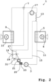
- FIG. 2 is an exemplary embodiment of one Heating and/or air conditioning system 1 with a refrigerant circuit 11 comprising a compressor 3, a condenser/gas cooler 5, an expansion element 7 designed as a thermostatic expansion valve and an evaporator 9, shown schematically.
- the air conveying device 6 is assigned to the condenser/gas cooler 5 and the air conveying device 10 is assigned to the evaporator 9.
- the refrigerant circuit 11 is operated transcritically or supercritically, for example with CO 2 as the refrigerant, so that the condenser/gas cooler 5 is designed as a gas cooler.
- a refrigerant circuit 11 that is operated in a subcritical manner is also conceivable.
- the first internal heat exchanger 13 is integrated between the condenser/gas cooler 5 and the expansion element 7. It is intended for heat exchange between the refrigerant of the refrigerant circuit 11 and the heat medium of the secondary circuit 15.
- the heat medium of the secondary circuit is water or a water-glycol mixture. Driven by the pump 17, the heat medium can circulate in the secondary circuit. It absorbs heat from the refrigerant in the first internal heat exchanger 13 downstream of the pump 17 and transports it towards the second internal heat exchanger 19.
- the first internal heat exchanger 13 and the second internal heat exchanger 19 are arranged relative to one another in such a way that they are thermally coupled or can be thermally coupled using the heat medium of the secondary circuit 15.
- the secondary circuit 15 has a bypass 27 for the second internal heat exchanger 19.
- the controllable valve 29 is arranged in this bypass 27.
- another controllable valve 31 is arranged in parallel in front of the internal heat exchanger 19 in the secondary circuit 15.
- the two valves 29 and 31 are connected via in Fig. 2 Control connections shown in dashed lines are automatically controlled by the controller 21. They are controlled in such a way that the volume flow portion of the heat medium in the secondary circuit 15, which flows through the bypass 27 and therefore not through the second internal heat exchanger 19, can be adjusted in size.
- the controller 21 receives the temperature value of the refrigerant from the temperature sensor 23 in the low-pressure area of the refrigerant circuit 11 in front of the compressor 3.
- the controller 21 receives the pressure value of the refrigerant from the pressure sensor 25 in the low pressure area of the refrigerant circuit 11 in front of the compressor 3.
- the controller 21 determines the actual value of the superheat of the refrigerant and compares this with a predetermined setpoint of the superheat of, for example, 10 ° K. Depending on whether the actual value of the superheat is above or below the setpoint, it regulates the control 21 uses the two valves 29 and 31 to increase or decrease the proportion of the volume flow of the heat medium through the bypass 27, so that the internal heat exchange via the first internal heat exchanger 13 and the second internal heat exchanger 19 is regulated down or up. In this exemplary embodiment, the pump performance of the pump 17 cannot be regulated.
- the heating and/or air conditioning system 1 is designed for heating and/or cooling air in the interior of a vehicle.
- FIG. 3 an exemplary embodiment of a heating and/or air conditioning system 1 with a secondary circuit 15, which is also designed as a heating circuit, is shown schematically.
- the compressor 3 condenser/gas cooler 5, first internal heat exchanger 13, the expansion element 7 designed as a thermostatic expansion valve, evaporator 9 and second internal heat exchanger 19, its refrigerant circuit 11 also includes a fluid-fluid heat exchanger 33.
- the condenser/gas cooler 5 is Air conveying device 6 and the evaporator 9 are assigned the air conveying device 10.
- One side of the fluid-fluid heat exchanger 33 is arranged in the high-pressure area between the compressor 3 and the condenser/gas cooler 5 in the refrigerant circuit 11.
- This fluid-fluid heat exchanger 33 is like the first internal heat exchanger 13 and the second internal heat exchanger 19 for heat exchange between refrigerant Refrigerant circuit 11 and heat medium of the secondary circuit 15 are provided.
- a bypass 37 which can be controlled with a valve 35, is arranged in the secondary circuit 15 for the fluid-fluid heat exchanger 33.
- the controller 21 controls via in Fig. 3
- the control connection shown in dashed lines automatically passes the controllable valve 35 and thus the proportion of the volume flow of the heat medium through the bypass 37 past the fluid-fluid heat exchanger 33.
- a further heat exchanger 39 which is designed as an air-fluid heat exchanger, is arranged in the secondary circuit 15 downstream of the fluid-fluid heat exchanger 33.
- the blower 41 is set up to convey air through the further heat exchanger 39 into the room or area to be heated. It is also conceivable that the further heat exchanger 39 is designed for direct heat exchange with an object to be heated, such as a traction battery.
- a bypass 45 which can be controlled with a valve 43, runs in the secondary circuit 15 to the further heat exchanger 39.
- the control 21 automatically controls the controllable valve 43 and thus the proportion of the volume flow of the heat medium through the bypass 45 past the further heat exchanger 39 via a control connection.
- the control 21 automatically controls the controllable valve 29 via a control connection and thus the proportion of the volume flow of the heat medium through the bypass 27 past the second internal heat exchanger 19.
- the heating medium is water or a water-glycol mixture.
- pump 17 When pump 17 is activated, which is in its Pump power can be regulated, the heat medium circulates in the secondary circuit 15. It absorbs heat from the refrigerant in the first internal heat exchanger 13 integrated between the capacitor 5 and the expansion element 7 in the high-pressure area of the refrigerant circuit 11. In the secondary circuit 15 further downstream, the heat medium absorbs additional heat from the refrigerant of the refrigerant circuit 11 in its volume flow proportion, which can be controlled via the valve 35 in the fluid-fluid heat exchanger 33.
- This heat absorbed in the fluid-fluid heat exchanger 33 is used for heating.
- a proportion of the volume flow of the heat medium which can be controlled via the valve 43, gives off heat to the further heat exchanger 39 in this heat for heating to the medium air conveyed by the fan 41.
- the first internal heat exchanger 13 and the second internal heat exchanger 19 are arranged relative to one another in such a way that they can be thermally coupled using the heat medium of the secondary circuit 15.
- the controller 21 receives the temperature value and the pressure value of the refrigerant there in the high-pressure range from the temperature sensor 23 and pressure sensor 25 arranged in the refrigerant circuit 11 in front of the expansion element 7. Furthermore, the controller 21 receives information about how much heating is required. From this information, the controller 21 automatically determines how the pump 17 and the valves 35, 43 and 29 are to be regulated and regulates them accordingly.
- the heating and/or air conditioning system 1 is designed for heating and/or cooling air in an interior of a vehicle, such as the passenger compartment of a rail vehicle.
- FIG. 4 an exemplary embodiment of a heating and/or air conditioning system 1 with a secondary circuit 15, which is also designed as a cooling circuit, is shown schematically. Except for the arrangement of the fluid-fluid heat exchanger 33, the bypass 37 that can be controlled with valve 35, the further heat exchanger 39 with fan 41 and the bypass 45 that can be controlled with valve 43, it corresponds to that in Fig. 3 Shown heating and/or air conditioning system 1. It therefore includes how to Fig.
- the fluid-fluid heat exchanger 33 is intended for heat exchange between the refrigerant of the refrigerant circuit 11 and the heat medium of the secondary circuit 15. In secondary circuit 15 it is closed
- the fluid-fluid heat exchanger 33 has a bypass 37 that can be controlled with a valve 35.
- a further heat exchanger 39 which is designed as an air-fluid heat exchanger, is arranged in the secondary circuit 15 downstream of the fluid-fluid heat exchanger 33. It is used to exchange heat with a medium, for example air for the interior of a vehicle.
- the blower 41 is set up to convey air through the further heat exchanger 39 into the room or area to be cooled. It is also conceivable that the further heat exchanger 39 is designed for direct heat exchange with an object to be cooled, such as a traction battery.
- a bypass 45 which can be controlled with a valve 43, runs in the secondary circuit 15 to the further heat exchanger 39.
- the heating medium is water or a water-glycol mixture.
- the heat medium circulates in the secondary circuit 15. It absorbs heat from the refrigerant in the first internal heat exchanger 13.
- the heat medium releases additional heat to the refrigerant of the refrigerant circuit 11 in its volume flow proportion, which can be controlled via the valve 35 in the fluid-fluid heat exchanger 33.
- the heat medium cooled down in this way is used for cooling.
- a portion of the volume flow of the heat medium that can be controlled via the valve 43 takes place to the further heat exchanger 39 in this heat for cooling the air conveyed by the fan 41.
- the controller 21 receives the temperature value and the pressure value of the refrigerant there in the high-pressure range from the temperature sensor 23 and pressure sensor 25 arranged in the refrigerant circuit 11 in front of the expansion element 7. Furthermore, the controller 21 receives information about how much cooling is required. From this information, the controller 21 automatically determines how the pump 17 and the valves 35, 43 and 29 are to be regulated and regulates these via the in Fig. 4 Control connections shown in dashed lines accordingly.
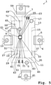
- a further exemplary embodiment of a heating and/or air conditioning system 1 is shown schematically. It comprises a refrigerant circuit 11, a secondary circuit 15 which is also designed as a heating circuit and a further secondary circuit 51 which is also designed as a cooling circuit, the third internal heat exchanger 53 being provided for heat exchange between the heat medium of the secondary circuit 15 and the further heat medium of the further secondary circuit 51.
- the compressor 3 In the refrigerant circuit 11, in the flow direction of the refrigerant, are the compressor 3, the fluid-fluid heat exchanger 33, the condenser/gas cooler 5, and the first internal heat exchanger 13, the expansion element 7 designed as a thermostatic expansion valve, the further fluid-fluid heat exchanger 55, the evaporator 9 and the second internal heat exchanger 19 are arranged.
- the refrigerant is, for example, CO 2 .
- the air conveying device 6 is assigned to the condenser/gas cooler 5 and the air conveying device 10 is assigned to the evaporator 9.
- the heat medium which is water or a water-glycol mixture
- the heat medium can be passed successively through the first internal heat exchanger 13, the fluid-fluid heat exchanger 33, the further heat exchanger 39 and the third internal one in the secondary circuit 15
- Pump heat exchanger 53 whereby instead of through the fluid-fluid heat exchanger 33, a portion of the volume flow of the heat medium that can be regulated in size with valve 35 can flow through the bypass 37 and instead of through the further heat exchanger 39, a portion that can be regulated in size with valve 43 can flow Volume flow of the heat medium can flow through the bypass 45.
- the fan 41 assigned to the further heat exchanger 39 conveys air as a medium into the room to be heated.
- the first internal heat exchanger 15 is thermally coupled to the third internal heat exchanger 53 via the heat medium in the secondary circuit 15. Via the heat exchange in the third internal heat exchanger 53, a thermal coupling with the further heat medium, which is water or a water-glycol mixture, of the further secondary circuit 51 is provided. During operation, the further heat medium circulates in the further secondary circuit 51, driven by a pump 57 whose pumping capacity can be regulated.
- the further heat medium which is water or a water-glycol mixture
- each of these heat exchangers in the further secondary circuit 51 having a bypass 27, 63, 67, 71 which can be controlled with a valve 29, 61, 65, 69 and instead of through the respective one Heat exchangers 19, 53, 55, 59 can flow through the respective bypass 27, 63, 67, 71, a portion of the volume flow of the further heat medium that can be regulated in size with the respective valve 29, 61, 65, 69.
- the fan 73 assigned to the further heat exchanger 59 conveys air as a medium into the room to be cooled.
- Second internal heat exchanger 19 flows via the heat medium of the secondary circuit 15, the third internal heat exchanger 53 and further via the further heat medium of the further secondary circuit 51.
- the first internal heat exchanger 13 and the second internal heat exchanger 19 are thus arranged in such a way that they can be used under other things, the heat medium of the secondary circuit 15 are thermally coupled or can be thermally coupled.
- the controller 21 receives from the temperature sensor 23 and pressure sensor 25 arranged in the high-pressure area of the refrigerant circuit 11 in front of the expansion element 7 and from the temperature sensor 75 and arranged in the low-pressure area of the refrigerant circuit 11 in front of the compressor 3 Pressure sensor 77 the temperature values and pressure values of the refrigerant in the respective area. Furthermore, the controller 21 receives information about how much cooling or heating is required. From this information, the controller 21 automatically determines how the pumps 17 and 57 as well as the valves 29, 35, 43, 61, 65 and 69 are to be regulated and regulates these via the in Fig. 5 Control connections shown in dashed lines accordingly.
- the heating and/or air conditioning system 1 is designed for heating and/or cooling air in an interior of a vehicle, such as a passenger compartment of a bus.
- a vehicle such as a passenger compartment of a bus.
- it can be designed as a rooftop system.
- FIG. 6 an exemplary embodiment of a vehicle 81 with a heating and/or air conditioning system 1 according to the invention is shown.
- the vehicle 81 is designed as a bus.
- the heating and/or air conditioning system 1 is mounted on the vehicle 81 as a roof-mounted system.
- she is one of the in Fig. 1 , 2 , 3 , 4 and 5 shown heating and / or air conditioning systems 1 and for heating and / or cooling air for the interior 83 of the vehicle 81 as set up in particular for the passenger compartment.
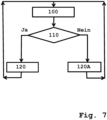
- FIG. 7 An exemplary embodiment of a method according to the invention is shown in a flowchart representation. It is a method for controlling a heating and/or air conditioning system according to the invention, such as that in Fig. 5 shown.
- step a pressure values in the refrigerant circuit with the corresponding pressure sensors and temperature values in the refrigerant circuit with the corresponding temperature sensors are determined by measurement.
- step aa it is determined based on the pressure values and temperature values determined in the first step 100 whether there is excessive overheating of the refrigerant upstream of the compressor and/or excessive undercooling of the refrigerant upstream of the expansion element /present.
- the boiling temperature of the refrigerant such as CO 2 , is determined for the respective measured pressure value. This is done using the function of the boiling temperature depending on the pressure according to the vapor pressure curve in the pressure-temperature relationship.
- a fictitious boiling temperature can be assumed for the measured pressure value.
- the temperature value of the refrigerant measured in the same area in the refrigerant circuit as the respective pressure value is compared with the boiling temperature or fictitious boiling temperature for the respective measured pressure value.
- the difference between the boiling temperature or fictitious boiling temperature minus the measured temperature value is formed.
- the difference is formed between the measured temperature value minus the boiling temperature.
- step 110 If the subcooling of the refrigerant in the area of the refrigerant circuit in front of the expansion element is above a threshold value specified for excessive subcooling For example, 20 °K, then in step 110 too much supercooling is assumed and otherwise not. The result of the determination is therefore affirmative if the hypothermia is greater than the threshold value. The same applies when determining whether the refrigerant is overheating too much in the area in front of the compressor. The determination is to be made in the affirmative if the overheating is greater than a predetermined threshold value of, for example, 15 °K.
- step 110 If either of the two determinations in step 110 is affirmative, the overall result in step 110 is “ yes. ” Then in step 120 the pump of the secondary circuit is deactivated or remains deactivated or there is at least one valve of a bypass according to claim 2 in the secondary circuit or, if the heating and / or air conditioning system includes the further secondary circuit, at least one valve of a bypass according to claim 2 or 4 in the further secondary circuit opens or remains open with respect to the bypass. This means that the internal heat exchange via the first and second internal heat exchangers is interrupted.
- step 110 If no determination is made in the affirmative in step 110, the overall result in step 110 is “ No ” . Then in step 120A the pump of the secondary circuit is activated or remains activated and, if present, every valve of a bypass according to claim 2 in the secondary circuit and, if the heating and / or air conditioning system includes the further secondary circuit, if present every valve of a bypass according to claim 2 and 4 are closed or remain closed with regard to the bypass.
- the method begins again after steps 120 or 120A after a predetermined period of time, for example 0.1 seconds.
- step 100 the temperature value of the refrigerant after the compressor is additionally determined using a temperature sensor in the high-pressure area of the refrigerant circuit downstream of the compressor.
- this measured temperature value is then compared with a predetermined threshold value of, for example, 150 ° C with, for example, the refrigerant CO 2 . If the threshold value is exceeded, the determination as to whether the temperature of the refrigerant downstream of the compressor is too high is answered in the affirmative and continues with step 120. Otherwise, if no determination is made in the affirmative in step 110, i.e. "No", the process continues with step 120A.
- Fig. 8 is a flowchart representation of a further exemplary embodiment of a method according to the invention for controlling a heating and / or air conditioning system according to the invention, such as that in Fig. 3 shown.
- a pressure value in the refrigerant circuit is determined with a pressure sensor in the high-pressure area between the compressor and expansion element and a temperature value of the refrigerant is determined with a temperature sensor in the high-pressure area of the refrigerant circuit in front of the expansion element.
- an actual value regarding subcooling of the refrigerant in the high-pressure region of the refrigerant circuit in front of the expansion element is determined based on the pressure value and temperature value determined in the first step 200.
- This determined actual value is the subcooling in °K.
- the determination is made to determine whether the actual value is greater or less than a setpoint of subcooling of, for example, 15 °K, and, depending on the result, a decision is made as to which step follows.
- step 230 follows, in which, the higher this difference is, the more the pumping power of the pump in the secondary circuit is increased and, if present, each valve of a bypass according to claim 2 in the secondary circuit and, provided that the heating and/or air conditioning system comprises the further secondary circuit, if present, each valve of a bypass according to claims 2 and 4 is further narrowed with respect to the bypass or remains closed. This means that the internal heat exchange via the first and second internal heat exchangers is increased more or less or remains at the maximum position depending on the size of the difference determined.
- step 220 is followed by step 230A, in which, the higher the difference, the more the pumping power of the secondary circuit pump is reduced and, if present, at least one Valve of a bypass according to claim 2 in the secondary circuit and / or, if the heating and / or air conditioning system is further Secondary circuit includes, if present, at least one valve of a bypass according to claim 2 or 4 with respect to the bypass, the further it is opened or remains completely open. This means that the internal heat exchange via the first and second internal heat exchangers is reduced to a greater or lesser extent or remains unchanged, depending on the size of the difference determined.
- the method begins again after steps 230 or 230A after a predetermined period of time, for example 0.1 seconds.
- the method counteracts a deviation of the subcooling from a specified target value at which the heating and/or air conditioning system runs particularly efficiently.
- Fig. 9 is a flowchart representation of a further exemplary embodiment of a method according to the invention for controlling a heating and / or air conditioning system according to the invention, such as that in Fig. 5 shown.
- a pressure value in the refrigerant circuit is determined with a pressure sensor in the low-pressure area between the expansion element and the compressor and a temperature value of the refrigerant is determined with a temperature sensor in the low-pressure area of the refrigerant circuit in front of the compressor.
- an actual value regarding overheating of the refrigerant in the low-pressure region of the refrigerant circuit in front of the compressor is determined based on the pressure value and temperature value determined in the first step 300.
- This determined actual value is the actual superheat in °K.
- step 320 is determined based on the determination of whether the actual value is greater or less than a setpoint of superheating of, for example, 8 °K, and, depending on the result, a decision is made as to which step follows.
- step 330 follows, in which, the higher this difference is, the more the pumping power of the pump in the secondary circuit is increased and, if present, each valve of a bypass according to claim 2 in the secondary circuit and, if the heating - and / or air conditioning includes the further secondary circuit, if present, each valve of a bypass according to claims 2 and 4 is narrowed further with respect to the bypass or remains closed.
- step 320 is followed by step 330A, in which, the higher the difference, the more the pumping power of the secondary circuit pump is reduced and, if present, at least one valve a bypass according to claim 2 in the secondary circuit and / or, if the heating and / or air conditioning system includes the further secondary circuit, if present at least one valve of a bypass according to claim 2 or 4 is opened the further with respect to the bypass or remains completely open.
- the method begins again after steps 330 or 330A after a predetermined period of time, for example 0.1 seconds.
- the method is used to determine a deviation in superheating from a specified setpoint the heating and/or air conditioning system runs particularly efficiently.
Landscapes
- Engineering & Computer Science (AREA)
- Mechanical Engineering (AREA)
- Physics & Mathematics (AREA)
- Thermal Sciences (AREA)
- General Engineering & Computer Science (AREA)
- Compression-Type Refrigeration Machines With Reversible Cycles (AREA)
- Air-Conditioning For Vehicles (AREA)
Description
Die Erfindung betrifft eine Heiz- und/oder Klimaanlage mit einem zumindest einen Verdichter, einen Kondensator/Gaskühler, ein Expansionsorgan und einen Verdampfer umfassenden Kältemittelkreis sowie mit wenigstens einem zumindest eine Pumpe für ein Wärmemedium umfassenden Sekundärkreis.The invention relates to a heating and/or air conditioning system with a refrigerant circuit comprising at least one compressor, a condenser/gas cooler, an expansion element and an evaporator, and with at least one secondary circuit comprising at least one pump for a heat medium.
Ferner betrifft die Erfindung ein Fahrzeug, wie insbesondere ein Omnibus oder Schienenfahrzeug, mit einer derartigen Heiz- und/oder Klimaanlage sowie ein Verfahren zum Steuern einer derartigen Heiz- und/oder Klimaanlage.The invention further relates to a vehicle, such as in particular a bus or rail vehicle, with such a heating and/or air conditioning system and to a method for controlling such a heating and/or air conditioning system.
In einem Kältemittelkreis zirkuliert bei Betrieb Kältemittel, wie beispielsweise CO2. Es wird vom Verdichter komprimiert und dadurch erhitzt und gelangt über Kältemittelleitung so in den Kondensator/Gaskühler, in dem es Wärme abgibt. Im Kältemittelkreis stromabwärts vom Kondensator/Gaskühler wird das Kältemittel im Expansionsorgan entspannt, wodurch es sich abkühlt und darauf im Verdampfer Wärme aufnimmt, um danach zum Saugeingang des Verdichters zu strömen. Zur Weiterleitung von Kältemittel zwischen Komponenten dienen im Kältemittelkreis Kältemittelleitungen. Ein Kondensator/Gaskühler ist entweder als ein Gaskühler für einen Kältemittelkreis, der im transkritischen beziehungsweise überkritischen Betrieb beispielweise mit CO2 als Kältemittel läuft, oder als ein Kondensator für einen Kältemittelkreis, der im unterkritischen Betrieb beispielsweise mit dem Kältemittel R-1234yf läuft, ausgebildet.During operation, refrigerant, such as CO 2 , circulates in a refrigerant circuit. It is compressed by the compressor and thereby heated and reaches the condenser/gas cooler via the refrigerant line, where it gives off heat. In the refrigerant circuit downstream from the condenser/gas cooler, the refrigerant is expanded in the expansion element, whereby it cools down and then absorbs heat in the evaporator in order to then flow to the suction inlet of the compressor. Refrigerant lines are used in the refrigerant circuit to transfer refrigerant between components. A condenser/gas cooler is either a gas cooler for a refrigerant circuit that runs in transcritical or supercritical operation, for example with CO 2 as a refrigerant, or as a condenser for a refrigerant circuit that runs in subcritical operation, for example with the refrigerant R-1234yf.
Bekannt sind Heiz- und/oder Klimaanlagen mit einem Kältemittelkreis, bei denen insbesondere zur Verbesserung der Effizienz im Kältemittelkreis zumindest ein interner Wärmetauscher zum internen Wärmetausch zwischen dem heißen Kältemittel im Hochdruckbereich im Kältemittelkreis stromabwärts des Kondensators/Gaskühlers und dem kalten Kältemittel im Niedrigdruckbereich im Kältemittelkreis stromabwärts des Verdampfers angeordnet ist. Zum Beispiel ist in
Der im Anspruch 1 angegebenen Erfindung liegt also die Aufgabe zugrunde, eine hinsichtlich internen Wärmetausches verbesserte Heiz- und/oder Klimaanlage mit Kältemittelkreis bereitzustellen.The invention specified in
Eine entsprechende Aufgabe liegt der in Anspruch 12 angegebenen Erfindung bezüglich der Bereitstellung eines Fahrzeugs mit einer Heiz- und/oder Klimaanlage zugrunde. Ferner liegt eine entsprechende weitere Aufgabe der in Anspruch 13
angegebenen Erfindung hinsichtlich der Bereitstellung eines Verfahrens zum Steuern einer Heiz- und/oder Klimaanlage zugrunde.A corresponding object is based on the invention specified in claim 12 with regard to the provision of a vehicle with a heating and/or air conditioning system. There is also a corresponding further task in
The invention is based on the provision of a method for controlling a heating and/or air conditioning system.
Die der im Anspruch 1 angegebenen Erfindung zugrundeliegende Aufgabe wird durch die im Anspruch 1 aufgeführten Merkmale gelöst. Die Aufgabe wird dadurch, dass bei der Heiz- und/oder Klimaanlage mit einem zumindest einen Verdichter, einen Kondensator/Gaskühler, ein Expansionsorgan und einen Verdampfer umfassenden Kältemittelkreis sowie mit wenigstens einem zumindest eine Pumpe für ein Wärmemedium, das Wasser oder Wasser-Glykol-Gemisch ist, umfassenden Sekundärkreis ohne Expansionsorgan im Hochdruckbereich des Kältemittelkreises zwischen dem Kondensator/Gaskühler und dem Expansionsorgan ein erster interner Wärmetauscher integriert ist, der für einen Wärmetausch zwischen Kältemittel des Kältemittelkreises und einem zum Wärmetransport vorgesehenen Wärmemedium des Sekundärkreises vorgesehen ist, und im Niedrigdruckbereich des Kältemittelkreises zwischen dem Verdampfer und Verdichter ein zweiter interner Wärmetauscher integriert ist, der für einen Wärmetausch zwischen dem Kältemittel des Kältemittelkreises und dem Wärmemedium des Sekundärkreises oder einem gegebenenfalls weiteren Wärmemedium eines gegebenenfalls weiteren Sekundärkreises vorgesehen ist, und der erste interne Wärmetauscher und der zweite interne Wärmetauscher derart angeordnet sind, dass sie mithilfe zumindest des Wärmemediums des Sekundärkreises thermisch gekoppelt oder thermisch koppelbar sind und die Pumpe des Sekundärkreises in ihrer Pumpleistung regelbar ist, gelöst.The object underlying the invention specified in
Im Hochdruckbereich des Kältemittelkreises steht bei Betrieb das stromabwärts des Verdichters komprimierte Kältemittel unter höherem Druck als im Niedrigdruckbereich mit entspanntem Kältemittel stromaufwärts des Verdichters. Das Wärmemedium im Sekundärkreis ist Wasser oder Wasser-Glykol-Gemisch.In the high-pressure area of the refrigerant circuit, the refrigerant compressed downstream of the compressor is under higher pressure during operation than in the low-pressure area with expanded refrigerant upstream of the compressor. The heat medium in the secondary circuit is water or a water-glycol mixture.
Die erfindungsgemäße Heiz- und/oder Klimaanlage hat den Vorteil, dass der interne Wärmetausch zwischen dem heißen Kältemittel im Hochdruckbereich im Kältemittelkreis stromabwärts des Kondensators/Gaskühlers und dem kalten Kältemittel im Niedrigdruckbereich im Kältemittelkreis stromabwärts des Verdampfers nicht direkt sondern indirekt mithilfe zumindest des Wärmemediums des wenigstens zwischengeschalteten Sekundärkreises erfolgen kann. Dadurch ist die Anordnung der Kältemittelleitungen hinsichtlich des internen Wärmtauschs nicht eingeschränkt und für das Regeln des internen Wärmetauschs ist kein zusätzliches Ventil im Kältemittelkreis notwendig, sondern ein Regeln des internen Wärmetauschs ist ohne direkten Eingriff in den Kältemittelkreis im Sekundärkreis und/oder, sofern die Heiz- und/oder Klimaanlage den weiteren Sekundärkreis aufweist, in diesem realisierbar. Durch diese Regelbarkeit des internen Wärmetauschs wird die Gefahr von zu großer Überhitzung des Kältemittels im Niedrigdruckbereich des Kältemittelkreises vor dem Verdichter sowie die Gefahr von zu großer Unterkühlung des Kältemittels im Hochdruckbereich vor dem Expansionsorgan verringert. Mittels der in ihrer Pumpleistung regelbaren Pumpe im Sekundärkreis kann der Volumenstrom von Wärmemedium durch den ersten internen Wärmetauscher im Sekundärkreis reguliert werden. Somit sind die Größe des Wärmetransports der über das Wärmemedium im ersten internen Wärmetauscher vom Kältemittel aufgenommenen Wärme und damit der interne Wärmetausch im Kältemittelkreis einfach regelbar. Bei einer stufenlos in ihrer Leistung regelbaren Pumpe im Sekundärkreis ist der interne Wärmtausch im Kältemittelkreis sogar stufenlos regelbar.The heating and/or air conditioning system according to the invention has the advantage that the internal heat exchange between the hot refrigerant in the high-pressure area in the refrigerant circuit downstream of the condenser/gas cooler and the cold refrigerant in the low pressure range in the refrigerant circuit downstream of the evaporator can not take place directly but indirectly using at least the heat medium of the at least intermediate secondary circuit. As a result, the arrangement of the refrigerant lines is not restricted with regard to the internal heat exchange and no additional valve is necessary in the refrigerant circuit to regulate the internal heat exchange, but rather the internal heat exchange can be regulated without direct intervention in the refrigerant circuit in the secondary circuit and/or, provided that the heating and / or air conditioning has the further secondary circuit, can be implemented in this. This controllability of the internal heat exchange reduces the risk of excessive overheating of the refrigerant in the low-pressure area of the refrigerant circuit upstream of the compressor and the risk of excessive undercooling of the refrigerant in the high-pressure area upstream of the expansion element. The volume flow of heat medium through the first internal heat exchanger in the secondary circuit can be regulated by means of the pump in the secondary circuit, whose pumping capacity can be regulated. This means that the size of the heat transport of the heat absorbed by the refrigerant via the heat medium in the first internal heat exchanger and thus the internal heat exchange in the refrigerant circuit can be easily regulated. With a pump in the secondary circuit whose output can be continuously regulated, the internal heat exchange in the refrigerant circuit can even be continuously regulated.
In den Unteransprüchen sind vorteilhafte Ausgestaltungen, Weiterbildungen und Verbesserungen des jeweiligen Gegenstandes der Erfindung angegeben.Advantageous refinements, further developments and improvements of the respective subject matter of the invention are specified in the subclaims.
Vorzugsweise weist/weisen der Sekundärkreis zum ersten internen Wärmetauscher einen mit Ventil regelbaren Bypass und/oder zum zweiten internen Wärmetauscher der Sekundärkreis oder, sofern die Heiz- und/oder Klimaanlage den weiteren Sekundärkreis umfasst, dieser weitere Sekundärkreis einen mit Ventil regelbaren Bypass auf. Damit lässt sich über das/die Ventil/e im Sekundärkreis der interne Wärmetausch im Kältemittelkreis einfach regeln. Sofern das Wärmemedium im Sekundärkreis durch den Bypass zum ersten internen Wärmetauscher und/oder durch den Bypass zum zweiten internen Wärmetauscher strömt, ist der sonstige Wärmetransport darüber zwischen ersten und zweiten internen Wärmetauscher unterbrochen, sodass ein interner Wärmetausch im Kältemittelkreis dann nicht stattfindet.Preferably, the secondary circuit has/have a bypass that can be controlled with a valve to the first internal heat exchanger and/or the secondary circuit to the second internal heat exchanger or, if the heating and/or air conditioning system includes the further secondary circuit, this further secondary circuit has a bypass that can be controlled with a valve. This allows the internal heat exchange in the refrigerant circuit to be easily regulated via the valve(s) in the secondary circuit. If the heat medium in the secondary circuit flows through the bypass to the first internal heat exchanger and/or through the bypass to the second internal heat exchanger, the other heat transport is interrupted between the first and second internal heat exchanger, so that an internal heat exchange in the refrigerant circuit does not take place.
Nach einer vorteilhaften Weiterbildung der erfindungsgemäßen Heiz- und/oder Klimaanlage, sofern sie den weiteren Sekundärkreis umfasst, umfasst dieser weitere Sekundärkreis eine Pumpe und einen zum Wärmetausch zwischen seinem weiteren Wärmemedium und dem Wärmemedium des Sekundärkreises vorgesehenen dritten internen Wärmetauscher. Damit ist auf einfache Weise ein interner Wärmetausch im Kältemittelkreis indirekt über das Wärmemedium des zwischengeschalteten Sekundärkreises und weiter über das weitere Wärmemedium des zwischengeschalteten weiteren Sekundärkreises ermöglicht. Besonders vorteilhaft ist dabei eine Ausführung, bei der der Sekundärkreis und/oder der weitere Sekundärkreis einen mit Ventil regelbaren Bypass zum dritten internen Wärmetauscher aufweist/aufweisen. Damit ist eine thermische Kopplung des Sekundärkreises mit dem weiteren Sekundärkreis einfach ein- und abschaltbar, was die Flexibilität hinsichtlich des internen Wärmetauschs erhöht.According to an advantageous development of the heating and/or air conditioning system according to the invention, provided that it includes the further secondary circuit, this further secondary circuit comprises a pump and a pump for heat exchange between it further heat medium and the third internal heat exchanger provided for the heat medium of the secondary circuit. This makes it possible to easily exchange internal heat in the refrigerant circuit indirectly via the heat medium of the intermediate secondary circuit and further via the further heat medium of the intermediate secondary circuit. Particularly advantageous is an embodiment in which the secondary circuit and/or the further secondary circuit has/have a bypass to the third internal heat exchanger that can be controlled with a valve. This means that a thermal coupling of the secondary circuit with the other secondary circuit can be easily switched on and off, which increases flexibility with regard to internal heat exchange.
Bevorzugt umfasst die erfindungsgemäße Heiz- und/oder Klimaanlage eine Steuerung ausgebildet zum automatischen Steuern der Aktivierung sowie Deaktivierung der Pumpe des Sekundärkreises und/oder deren Pumpleistung und/oder des/der zum Regeln der Strömung durch den Bypass oder die Bypässe vorgesehenen Ventil(s)/e. Dadurch ist ein indirektes automatisches Steuern des internen Wärmetauschs im Kältemittelkreis ohne in den Kältemittelkreis direkt einzugreifen ermöglicht.The heating and/or air conditioning system according to the invention preferably comprises a controller designed to automatically control the activation and deactivation of the pump of the secondary circuit and/or its pumping power and/or the valve(s) provided for regulating the flow through the bypass or bypasses. /e. This enables indirect, automatic control of the internal heat exchange in the refrigerant circuit without directly intervening in the refrigerant circuit.
Nach einer vorteilhaften Weiterbildung der erfindungsgemäßen Heiz- und/oder Klimaanlage ist/sind ein Temperatursensor im Niedrigdruckbereich des Kältemittelkreises vor dem Verdichter und/oder ein Temperatursensor im Hochdruckbereich des Kältemittelkreises nach dem Verdichter und/oder vor dem Expansionsorgan angeordnet und ist die Steuerung derart ausgebildet, dass in Abhängigkeit vom/von mit dem/den Temperatursensor/en gemessenen Temperaturwert/en die Aktivierung sowie Deaktivierung der Pumpe des Sekundärkreises und/oder deren Pumpleistung und/oder das/die zum Regeln der Strömung durch den Bypass oder die Bypässe vorgesehene/n Ventil/e automatisch steuerbar ist/sind. Dadurch ist die das Regeln des internen Wärmetauschs insbesondere gegen zu große Überhitzung des Kältemittels vor dem Verdichter und zu große Unterkühlung des Kältemittels vor dem Expansionsorgan verbessert.According to an advantageous development of the heating and/or air conditioning system according to the invention, a temperature sensor is/are arranged in the low-pressure region of the refrigerant circuit in front of the compressor and/or a temperature sensor in the high-pressure region of the refrigerant circuit after the compressor and/or in front of the expansion element and the control is designed in such a way that that depending on the temperature value(s) measured with the temperature sensor(s), the activation and deactivation of the pump of the secondary circuit and/or its pumping power and/or the valve(s) provided for regulating the flow through the bypass or bypasses /e is/are automatically controllable. This makes it possible to regulate the internal heat exchange, especially against excessive overheating Refrigerant in front of the compressor and excessive subcooling of the refrigerant in front of the expansion element.
Gemäß einer vorteilhaften Weiterbildung der erfindungsgemäßen Heiz- und/oder Klimaanlage ist/sind ein Drucksensor im Niedrigdruckbereich des Kältemittelkreises zwischen Expansionsorgan und Verdichter und/oder ein Drucksensor im Hochdruckbereich des Kältemittelkreises zwischen Verdichter und Expansionsorgan angeordnet und ist die Steuerung derart ausgebildet, dass in Abhängigkeit vom/von mit dem/den Drucksensor/en gemessenen Druckwert/en die Aktivierung sowie Deaktivierung der Pumpe des Sekundärkreises und/oder deren Pumpleistung und/oder das/die zum Regeln der Strömung durch den Bypass oder die Bypässe vorgesehene/n Ventil/e automatisch steuerbar ist/sind. Somit lassen sich Gefahren für den Kältemittelkreis durch entsprechendes Regeln des internen Wärmetauschs entgegenwirken. Besonders von Vorteil ist eine derartige Heiz- und/Klimaanlage, die auch noch Temperatursensor/en im Kältemittelkreis aufweist und mit der Steuerung der interne Wärmetausch abhängig von den gemessenen Druckwert/en und Temperaturwert/en des Kältemittels automatisch steuerbar ist.According to an advantageous development of the heating and/or air conditioning system according to the invention, a pressure sensor is/are arranged in the low-pressure region of the refrigerant circuit between the expansion element and the compressor and/or a pressure sensor in the high-pressure region of the refrigerant circuit between the compressor and the expansion element, and the control is designed in such a way that, depending on the /from pressure value(s) measured with the pressure sensor(s), the activation and deactivation of the pump of the secondary circuit and/or its pumping power and/or the valve(s) provided for regulating the flow through the bypass or bypasses can be automatically controlled is/are. This means that dangers to the refrigerant circuit can be counteracted by appropriately regulating the internal heat exchange. Such a heating and/or air conditioning system is particularly advantageous, which also has temperature sensor(s) in the refrigerant circuit and with the control the internal heat exchange can be automatically controlled depending on the measured pressure value(s) and temperature value(s) of the refrigerant.
Nach einer vorteilhaften Ausführung der erfindungsgemäßen Heiz- und Klimaanlage ist der Sekundärkreis als Heizkreis und/oder Kühlkreis mit zumindest einem weiteren Wärmetauscher für einen Wärmetausch mit einem zu kühlenden und/oder zu heizenden Medium oder Objekt ausgebildet. Somit ist der Sekundärkreis neben dem internen Wärmetausch für eine weitere Funktion einsetzbar. Besonders von Vorteil ist dabei eine Ausführung, bei der der Sekundärkreis jeweils zu dem/den zumindest eine weitere Wärmetauscher einen mit Ventil regelbaren Bypass umfasst. Damit ist auf einfache Weise der weitere Wärmetauscher im Sekundärkreis zuschalt- und abschaltbar. Als Kühlkreis ausgebildet ist von Vorteil, wenn der Sekundärkreis auch noch zur Verstärkung der Kühlleistung einen weiteren Fluid-Fluid-Wärmetauscher, der auch Verdampfer im Niedrigdruckbereich des Kältemittelkreises ist, aufweist. Als Heizkreis ausgebildet ist von Vorteil, wenn der Sekundärkreis auch noch zur Verstärkung der Heizleistung einen weiteren Fluid-Fluid-Wärmetauscher, der auch Kondensator/Gaskühler im Hochdruckbereich des Kältemittelkreises ist, aufweist.According to an advantageous embodiment of the heating and air conditioning system according to the invention, the secondary circuit is designed as a heating circuit and/or cooling circuit with at least one further heat exchanger for heat exchange with a medium or object to be cooled and/or heated. The secondary circuit therefore has another function in addition to the internal heat exchange usable. Particularly advantageous is an embodiment in which the secondary circuit includes a bypass that can be controlled with a valve for the at least one further heat exchanger. This means that the additional heat exchanger in the secondary circuit can be switched on and off in a simple manner. Designed as a cooling circuit, it is advantageous if the secondary circuit also has a further fluid-fluid heat exchanger, which is also an evaporator in the low-pressure region of the refrigerant circuit, to increase the cooling performance. Designed as a heating circuit, it is advantageous if the secondary circuit also has a further fluid-fluid heat exchanger, which is also a condenser/gas cooler in the high-pressure area of the refrigerant circuit, to increase the heating output.
Nach einer weiteren vorteilhaften Ausführung der erfindungsgemäßen Heiz- und Klimaanlage ist, sofern sie den weiteren Sekundärkreis umfasst, dieser als Kühlkreis mit zumindest einem weiteren Wärmetauscher für einen Wärmetausch mit einem zu kühlenden Medium oder Objekt ausgebildet. Somit ist der weitere Sekundärkreis neben dem internen Wärmetausch für eine weitere Funktion einsetzbar. Besonders von Vorteil ist dabei eine Ausführung, die jeweils zu dem/den zumindest eine weitere Wärmetauscher einen mit Ventil regelbaren Bypass im weiteren Sekundärkreis umfasst. Dadurch ist auf einfache Weise der weitere Wärmetauscher im weiteren Sekundärkreis zuschalt- und abschaltbar. Als Kühlkreis ausgebildet ist von Vorteil, wenn der weitere Sekundärkreis auch noch zur Verstärkung der Kühlleistung einen weiteren Fluid-Fluid-Wärmetauscher, der auch Verdampfer im Niedrigdruckbereich des Kältemittelkreises ist, aufweist.According to a further advantageous embodiment of the heating and air conditioning system according to the invention, if it includes the further secondary circuit, this is designed as a cooling circuit with at least one further heat exchanger for heat exchange with a medium or object to be cooled. This means that the additional secondary circuit can be used for another function in addition to the internal heat exchange. Particularly advantageous is an embodiment that includes a bypass in the further secondary circuit that can be controlled with a valve in addition to the at least one further heat exchanger. This means that the additional heat exchanger in the additional secondary circuit can be switched on and off in a simple manner. Designed as a cooling circuit, it is advantageous if the further secondary circuit also has a further fluid-fluid heat exchanger, which is also an evaporator in the low-pressure region of the refrigerant circuit, to increase the cooling performance.
Vorzugsweise ist die erfindungsgemäße Heiz- und/oder Klimaanlage für das Heizen und/oder Kühlen von Luft eines Innenraums eines Fahrzeugs, wie insbesondere eines Fahrgastraums eines Omnibusses oder Schienenfahrzeugs, ausgebildet.The heating and/or air conditioning system according to the invention is preferably designed for heating and/or cooling air in an interior of a vehicle, such as in particular a passenger compartment of a bus or rail vehicle.
Die der Bereitstellung eines Fahrzeugs mit einer Heiz- und/oder Klimaanlage zugrundeliegende Aufgabe wird durch ein Fahrzeug, wie insbesondere ein Omnibus oder Schienenfahrzeug, mit einer erfindungsgemäßen Heiz- und/oder Klimaanlage gelöst. Die Vorteile sowie vorteilhafte Ausgestaltungen und Weiterbildungen gelten entsprechend den oben aufgeführten Vorzügen sowie vorteilhafter Ausgestaltungen und Weiterbildungen zur erfindungsgemäßen Heiz- und/oder Klimaanlage.The task underlying the provision of a vehicle with a heating and/or air conditioning system is achieved by a vehicle, such as in particular a bus or rail vehicle, with a heating and/or air conditioning system according to the invention. The advantages as well as advantageous refinements and further developments apply in accordance with the advantages listed above as well as advantageous refinements and further developments to the heating and/or air conditioning system according to the invention.
Die Aufgabe bezüglich der Bereitstellung eines Verfahrens wird durch ein Verfahren zum Steuern einer erfindungsgemäßen Heiz- und/oder Klimaanlage mit den Schritten, des in Schritt a) Ermittelns wenigstens eines Druckwertes im Kältemittelkreis und/oder wenigstens eines Temperaturwertes im Kältemittelkreis und/oder des Betriebszustandes des Kältemittelkreises, und des in Schritt b) abhängig vom wenigstens einen ermittelten Druckwert und/oder vom wenigstens einen ermittelten Temperaturwert und/oder vom ermittelten Betriebszustand Regelns der Aktivierung sowie Deaktivierung der Pumpe des Sekundärkreises und/oder deren Pumpleistung und/oder des/der Ventil(s)/e des/der Bypasses/Bypässe im Sekundärkreis und/oder, sofern die Heiz- und/oder Klimaanlage den weiteren Sekundärkreis umfasst, im weiteren Sekundärkreis, gelöst. Die Vorteile gelten entsprechend den oben aufgeführten Vorzügen sowie vorteilhafter Ausgestaltungen und Weiterbildungen zur erfindungsgemäßen Heiz- und/oder Klimaanlage. Mit dem Verfahren lässt sich vorteilhaft der interne Wärmetausch regeln und damit auf den Kältemittelkreis einwirken ohne direkt in diesen einzugreifen.The object of providing a method is achieved by a method for controlling a heating and/or air conditioning system according to the invention with the steps of determining in step a) at least one pressure value in the refrigerant circuit and/or at least one temperature value in the refrigerant circuit and/or the operating state of the Refrigerant circuit, and that determined in step b) depending on the at least one Pressure value and/or the at least one determined temperature value and/or the determined operating state of regulating the activation and deactivation of the pump of the secondary circuit and/or its pumping power and/or the valve(s) of the bypass(es) in the secondary circuit and /or, if the heating and/or air conditioning system includes the further secondary circuit, solved in the further secondary circuit. The advantages apply in accordance with the advantages listed above as well as advantageous refinements and further developments to the heating and/or air conditioning system according to the invention. The process can advantageously be used to regulate the internal heat exchange and thus influence the refrigerant circuit without directly intervening in it.
Besonders vorteilhaft ist ein derartiges Verfahren, bei dem in einem Zwischenschritt aa) anhand des/der in Schritt a) ermittelten Druckwert/e und/oder Temperaturwert/e festgestellt wird, ob eine zu große Überhitzung des Kältemittels vor dem Verdichter und/oder eine zu große Unterkühlung des Kältemittels vor dem Expansionsorgan und/oder eine zu hohe Temperatur des Kältemittels nach dem Verdichter vorliegt/vorliegen, und dass entweder, falls zumindest eine Feststellung im Zwischenschritt aa) zu bejahen ist, im Schritt b) die Pumpe des Sekundärkreises deaktiviert wird beziehungsweise bleibt oder deren Pumpleistung reduziert wird und/oder zumindest ein Ventil eines Bypasses nach Anspruch 2 im Sekundärkreis oder, sofern die Heiz- und/oder Klimaanlage den weiteren Sekundärkreis umfasst, zumindest ein Ventil eines Bypasses nach Anspruch 2 oder 4 im weiteren Sekundärkreis bezüglich des Bypasses geöffnet wird beziehungsweise bleibt oder weiter geöffnet wird, oder dass, falls keine Feststellung im Zwischenschritt aa) zu bejahen ist, im Schritt b) die Pumpe des Sekundärkreises aktiviert wird beziehungsweise bleibt oder auch deren Pumpleistung erhöht wird und falls vorhanden jedes Ventil eines Bypasses nach Anspruch 2 im Sekundärkreis und, sofern die Heiz- und/oder Klimaanlage den weiteren Sekundärkreis umfasst, falls vorhanden jedes Ventil eines Bypasses nach Anspruch 2 und 4 bezüglich des Bypasses geschlossen wird beziehungsweise bleibt.A method of this type is particularly advantageous in which, in an intermediate step aa), it is determined based on the pressure value(s) and/or temperature value(s) determined in step a) whether there is excessive overheating of the refrigerant upstream of the compressor and/or too much there is a large degree of undercooling of the refrigerant upstream of the expansion element and/or the temperature of the refrigerant downstream of the compressor is too high, and that either, if at least one finding in intermediate step aa) is affirmative, the pump of the secondary circuit is deactivated in step b). remains or whose pumping power is reduced and / or at least one valve of a bypass according to claim 2 in the secondary circuit or, if the heating and / or air conditioning system includes the further secondary circuit, at least one valve of a bypass according to claim 2 or 4 in the further secondary circuit with respect to the bypass is opened or remains or is opened further, or that, if no determination in intermediate step aa) is affirmative, in step b) the pump of the secondary circuit is activated or remains or its pumping power is increased and, if present, each valve of a bypass according to claim 2 in the secondary circuit and, if the heating and / or air conditioning system includes the further secondary circuit, if present, each valve of a bypass according to claims 2 and 4 is or remains closed with respect to the bypass.
Dadurch ist vorteilhaft ein Schutz vor Gefahren für die Heiz- und/oder Klimaanlage wegen zu großer Überhitzung vor dem Verdichter oder zu großer Unterkühlung vor dem Expansionsorgan oder zu hoher Temperatur des Kältemittels nach dem Verdichter eingerichtet. Eine zu große Überhitzung kann zum Beispiel ab einem vorgegebenen Schwellenwert von 15 °K Überhitzung angenommen werden. Eine zu große Unterkühlung kann beispielsweise ab einem vorgegebenen Schwellenwert von 20 °K Unterkühlung angenommen werden. Eine zu hohe Temperatur des Kältemittels nach dem Verdichter kann zum Beispiel ab einem vorgegebenen Schwellenwert von 150 °C bei CO2 als Kältemittel angenommen werden. Die Größe beziehungsweise der Wert der Überhitzung ist die Differenz zwischen dem tatsächlich bei gemessenem Druck gemessenen Temperaturwert und der sich aus der Dampfdruckkurve im Druck-Temperatur-Diagramm bei dem gemessenen Druck ergebenden niedrigeren Siedetemperatur. Die Dampfdruckkurve lässt sich aus der Funktion ![]()
![]()
![]()
![]()
Dabei ist T in °C einzusetzen, und p ergibt sich in barabsolut.T is to be entered in °C, and p is given in bar absolute .
Die Größe beziehungsweise der Wert der Unterkühlung ist die Differenz der sich aus der Dampfdruckkurve im Druck-Temperatur-Diagramm bei dem gemessenen Druck ergebenden Siedetemperatur und dem tatsächlich bei dem gemessenen Druck gemessenen niedrigeren Temperaturwert. Dabei wird für den Bereich über die kritische Temperatur hinaus die Dampfdruckkurve extrapoliert, wobei die Siedetemperatur dort nur fiktiv zur Ermittlung der Unterkühlung angenommen wird.The size or value of subcooling is the difference between the boiling temperature resulting from the vapor pressure curve in the pressure-temperature diagram at the measured pressure and the lower temperature value actually measured at the measured pressure. The vapor pressure curve is extrapolated for the area beyond the critical temperature, whereby the boiling temperature there is only fictitiously assumed to determine subcooling.
In einer vorteilhaften Weiterbildung des erfindungsgemäßen Verfahrens werden zumindest im Schritt a) ein Druckwert im Kältemittelkreis mit einem Drucksensor im Hochdruckbereich zwischen Verdichter und Expansionsorgan und ein Temperaturwert mit einem Temperatursensor im Hochdruckbereich vor dem Expansionsorgan ermittelt, und es wird anhand des/der in Schritt a) ermittelten Druckwert(s)/e und Temperaturwert(s)/e ein Istwert bezüglich einer Unterkühlung des Kältemittels im Hochdruckbereich des Kältemittelkreises vor dem Expansionsorgan festgestellt, und es wird bei niedrigerem Istwert bezüglich einer Unterkühlung des Kältemittels als ein Sollwert der Unterkühlung, je höher diese Differenz ist, im Schritt b) die Pumpleistung der Pumpe des Sekundärkreises desto mehr erhöht und falls vorhanden jedes Ventil eines Bypasses nach Anspruch 2 im Sekundärkreis und, sofern die Heiz- und/oder Klimaanlage den weiteren Sekundärkreis umfasst, falls vorhanden jedes Ventil eines Bypasses nach Anspruch 2 und 4 bezüglich des Bypasses desto weiter verengt beziehungsweise bleibt geschlossen, oder es wird bei höherem Istwert der Unterkühlung des Kältemittels als ein Sollwert der Unterkühlung, je höher diese Differenz ist, im Schritt b) die Pumpleistung der Pumpe des Sekundärkreises desto mehr verringert und falls vorhanden zumindest ein Ventil eines Bypasses nach Anspruch 2 im Sekundärkreis und/oder, sofern die Heiz- und/oder Klimaanlage den weiteren Sekundärkreis umfasst, falls vorhanden zumindest ein Ventil eines Bypasses nach Anspruch 2 oder 4 bezüglich des Bypasses desto weiter geöffnet beziehungsweise bleibt vollständig geöffnet. Damit wird, ohne direkt in den Kältemittelkreis einzugreifen, auf den Kältemittelkreis in der Weise eingewirkt, dass möglichst die Unterkühlung in den Bereich des Sollwerts von beispielsweise 15 °K gebracht beziehungsweise dort gehalten wird. Damit wird beziehungsweise bleibt die Heiz- und/oder Klimaanlage effizient.In an advantageous development of the method according to the invention, at least in step a), a pressure value in the refrigerant circuit is determined with a pressure sensor in the high-pressure area between the compressor and expansion element and a temperature value with a temperature sensor in the high-pressure area in front of the expansion element, and it is based on the in step a). determined pressure value (s) / e and temperature value (s) / e an actual value with regard to subcooling of the refrigerant in the high pressure area of the refrigerant circuit in front of the expansion element is determined, and it is lower than the actual value with regard to subcooling of the refrigerant as a setpoint of the subcooling, the higher it is Difference is, in step b) the pumping power of the secondary circuit pump is the more increased and, if present, each valve of a bypass according to claim 2 in the secondary circuit and, if the heating and / or air conditioning system includes the further secondary circuit, if present, each valve of a bypass according to claims 2 and 4 with respect to the bypass is narrowed the further or remains closed, or If the actual value of the subcooling of the refrigerant is higher than a setpoint of the subcooling, the higher this difference is, the more the pumping power of the pump in the secondary circuit is reduced in step b) and, if present, at least one valve of a bypass according to claim 2 in the secondary circuit and / or If the heating and/or air conditioning system includes the further secondary circuit, if present at least one valve of a bypass according to claim 2 or 4 with respect to the bypass is opened the further or remains completely open. This means that, without intervening directly in the refrigerant circuit, the refrigerant circuit is acted upon in such a way that, if possible, the subcooling is brought into the range of the setpoint of, for example, 15 °K or maintained there. This means that the heating and/or air conditioning system becomes or remains efficient.
In einer weiteren vorteilhaften Weiterbildung des erfindungsgemäßen Verfahrens werden zumindest im Schritt a) ein Druckwert im Kältemittelkreis mit einem Drucksensor im Niedrigdruckbereich zwischen Expansionsorgan und Verdichter und ein Temperaturwert mit einem Temperatursensor im Niedrigdruckbereich vor dem Verdichter ermittelt, und es wird anhand des/der in Schritt a) ermittelten Druckwert(s)/e und Temperaturwert(s)/e ein Istwert bezüglich einer Überhitzung des Kältemittels im Niedrigdruckbereich des Kältemittelkreises vor dem Verdichter festgestellt, und es wird bei niedrigerem Istwert bezüglich einer Überhitzung des Kältemittels als ein Sollwert der Überhitzung, je höher diese Differenz ist, im Schritt b) die Pumpleistung der Pumpe des Sekundärkreises desto mehr erhöht und falls vorhanden jedes Ventil eines Bypasses nach Anspruch 2
- im Sekundärkreis und, sofern die Heiz- und/oder Klimaanlage den weiteren Sekundärkreis umfasst, falls vorhanden jedes Ventil eines Bypasses nach Anspruch 2 und 4
- bezüglich des Bypasses desto weiter verengt beziehungsweise bleibt geschlossen, oder es wird bei höherem Istwert der Überhitzung des Kältemittels als ein Sollwert der Überhitzung, je höher diese Differenz ist, im Schritt b) die Pumpleistung der Pumpe des Sekundärkreises desto mehr verringert und falls vorhanden zumindest ein Ventil eines Bypasses nach Anspruch 2 im Sekundärkreis und/oder, sofern die Heiz- und/oder Klimaanlage den weiteren Sekundärkreis umfasst, falls vorhanden zumindest ein Ventil eines Bypasses nach Anspruch 2 oder 4 bezüglich des Bypasses desto weiter geöffnet beziehungsweise bleibt vollständig geöffnet. Damit wird, ohne direkt in den Kältemittelkreis einzugreifen, auf den Kältemittelkreis in der Weise eingewirkt, dass möglichst die Überhitzung in den Bereich des Sollwerts von beispielsweise 10 °K gebracht beziehungsweise dort gehalten wird. Damit wird beziehungsweise bleibt die Heiz- und/oder Klimaanlage effizient.
- in the secondary circuit and, if the heating and / or air conditioning system includes the further secondary circuit, if present, each valve of a bypass according to claims 2 and 4
- with regard to the bypass, the further it narrows or remains closed, or if the actual value of the superheat of the refrigerant is higher than a setpoint of the superheat, the higher this difference is, the more the pumping power of the pump of the secondary circuit is reduced in step b) and, if present, at least one Valve of a bypass according to claim 2 in the secondary circuit and / or, if the heating and / or air conditioning system includes the further secondary circuit, if present at least one valve of a bypass according to claim 2 or 4 with respect to the bypass is opened the further or remains completely open. This means that, without intervening directly in the refrigerant circuit, the refrigerant circuit is acted upon in such a way that, if possible, the superheat is brought into the range of the setpoint of, for example, 10 °K or is maintained there. This means that the heating and/or air conditioning system becomes or remains efficient.
Schließlich können die Merkmale der Unteransprüche für das erfindungsgemäße Verfahren im Wesentlichen frei miteinander und nicht durch die den Ansprüchen vorliegende Reihenfolge festgelegt kombiniert werden.Finally, the features of the subclaims for the method according to the invention can be combined essentially freely with one another and not determined by the order in which the claims are presented.
Anhand der Zeichnungen werden Ausführungsbeispiele der Erfindung erläutert.Exemplary embodiments of the invention are explained using the drawings.
Es zeigen
-
Fig. 1 in schematischer Darstellung ein Ausführungsbeispiel einer Heiz- und/oder Klimaanlage, -
Fig. 2 in schematischer Darstellung ein weiteres Ausführungsbeispiel einer Heiz- und/oder Klimaanlage, -
Fig. 3 in schematischer Darstellung ein Ausführungsbeispiel einer Heiz- und/oder Klimaanlage mit einem auch als Heizkreis ausgebildeten Sekundärkreis, -
Fig. 4 in schematischer Darstellung ein Ausführungsbeispiel einer Heiz- und/oder Klimaanlage mit einem auch als Kühlkreis ausgebildeten Sekundärkreis, -
Fig. 5 in schematischer Darstellung ein Ausführungsbeispiel einer Heiz- und/oder Klimaanlage mit einem auch als Kühlkreis ausgebildeten weiteren Sekundärkreis, -
Fig. 6 ein Ausführungsbeispiel eines Fahrzeugs mit einer erfindungsgemäßen Heiz- und/oder Klimaanlage, -
Fig. 7 in Flussdiagrammdarstellung ein Ausführungsbeispiel eines erfindungsgemäßen Verfahrens, -
Fig. 8 in Flussdiagrammdarstellung ein weiteres Ausführungsbeispiel eines erfindungsgemäßen Verfahrens, und -
Fig. 9 in Flussdiagrammdarstellung ein weiteres Ausführungsbeispiel eines erfindungsgemäßen Verfahrens.
-
Fig. 1 a schematic representation of an exemplary embodiment of a heating and/or air conditioning system, -
Fig. 2 a schematic representation of a further exemplary embodiment of a heating and/or air conditioning system, -
Fig. 3 a schematic representation of an exemplary embodiment of a heating and/or air conditioning system with a secondary circuit also designed as a heating circuit, -
Fig. 4 a schematic representation of an exemplary embodiment of a heating and/or air conditioning system with a secondary circuit that is also designed as a cooling circuit, -
Fig. 5 a schematic representation of an exemplary embodiment of a heating and/or air conditioning system with a further secondary circuit which is also designed as a cooling circuit, -
Fig. 6 an embodiment of a vehicle with a heating and/or air conditioning system according to the invention, -
Fig. 7 a flowchart representation of an exemplary embodiment of a method according to the invention, -
Fig. 8 a flowchart representation of a further exemplary embodiment of a method according to the invention, and -
Fig. 9 a flowchart representation of a further exemplary embodiment of a method according to the invention.
Alle Zeichnungen sind schematisch zu verstehen. Auf maßstabsgetreue Abbildungen wurde zum Zwecke erhöhter Klarheit der Darstellung verzichtet.All drawings are to be understood schematically. Figures that are true to scale have been omitted for the purpose of increasing the clarity of the illustration.
In
Heiz- und/oder Klimaanlage 1 mit einem einen Verdichter 3, einen Kondensator/Gaskühler 5, ein als thermostatisches Expansionsventil ausgebildetes Expansionsorgan 7 und einen Verdampfer 9 umfassenden Kältemittelkreis 11 schematisch gezeigt. Dem Kondensator/Gaskühler 5 ist die Luftfördereinrichtung 6 und dem Verdampfer 9 die Luftfördereinrichtung 10 zugeordnet. In diesem Fall wird der Kältemittelkreis 11 transkritisch beziehungsweise überkritisch beispielsweise mit CO2 als Kältemittel betrieben, sodass der Kondensator/Gaskühler 5 als Gaskühler ausgebildet ist. Denkbar ist auch ein Kältemittelkreis 11, der unterkritisch mit zum Beispiel dem Kältemittel R-1234yf betrieben wird, wobei der Kondensator/Gaskühler 5 als Kondensator ausgebildet ist. Im Hochdruckbereich des Kältemittelkreises 11 ist zwischen dem Kondensator/Gaskühler 5 und dem Expansionsorgan 7 der erste interne Wärmetauscher 13 integriert. Er ist als Fluid-Fluid-Wärmetauscher ausgebildet, der für einen Wärmetausch zwischen Kältemittel des Kältemittelkreises 11 und Wärmemedium des Sekundärkreises 15 vorgesehen ist. Das Wärmemedium des Sekundärkreises ist Wasser oder ein Wasser-Glykol-Gemisch. Antreibbar von einer in der Pumpleistung regelbaren Pumpe 17 kann das Wärmemedium im Sekundärkreis 15 geregelt zirkulieren. Es nimmt stromabwärts der Pumpe 17 vom Kältemittel im ersten internen Wärmetauscher 13 Wärme auf und transportiert diese zum zweiten internen Wärmetauscher 19, der als Fluid-Fluid-Wärmetauscher ausgebildet ist. Dieser einerseits im Sekundärkreis 15 integrierte zweite interne Wärmetauscher 19 ist andererseits im Niedrigdruckbereich des Kältemittelkreises 11 zwischen dem Verdampfer 9 und dem Verdichter 3 integriert und für einen Wärmetausch zwischen Kältemittel des Kältemittelkreises 11 und Wärmemedium des Sekundärkreises 15 vorgesehen. Zumindest ein Teil der vom Wärmemedium zum zweiten Wärmetauscher 19 im Sekundärkreis 15 transportierten Wärme wird dort an das Kältemittel des Kältemittelkreises 11 wieder abgegeben. Somit sind der erste interne Wärmetauscher 13 und der zweite interne Wärmetauscher 19 derart zueinander angeordnet, dass sie mithilfe des Wärmemediums des Sekundärkreises 15 thermisch gekoppelt beziehungsweise thermisch koppelbar sind. So thermisch gekoppelt und geregelt durch die in der Pumpleistung regelbaren Pumpe 17 erfüllen sie zusammen, jedoch ohne dabei direkt in den Kältemittelkreis 11 einzugreifen, die entsprechende Funktion wie ein über ein vorgeschaltetes Expansionsorgan geregelter interner Kältemittel-Kältemittel-Wärmetauscher im herkömmlichen Sinne. Die Pumpleistung der Pumpe 17 wird von der Steuerung 21 über in
Heating and/or
Denkbar ist auch eine Variante der Heiz- und/oder Klimaanlage 1, bei der die Pumpe 17 in der Pumpleistung nicht regelbar ist, und sie je nach Betriebszustand des Kältemittelkreises 11 aktiviert oder deaktiviert ist, wie beispielsweise im Klimabetrieb aktiviert und im Wärmepumpenbetrieb, also Heizbetrieb, deaktiviert ist. Eine Steuerung 21, ein Temperatursensor 23 und ein Drucksensor 25 wären für eine derartige Klima- und/oder Heizanlage entbehrlich.A variant of the heating and/or
Die Heiz- und/oder Klimaanlage 1 ist für das Heizen und/oder Kühlen von Luft eines Innenraums eines Fahrzeugs, wie beispielsweise eines Fahrgastraums eines Omnibusses, ausgebildet.The heating and/or
In
Heiz- und/oder Klimaanlage 1 mit einem einen Verdichter 3, einen Kondensator/Gaskühler 5, ein als thermostatisches Expansionsventil ausgebildetes Expansionsorgan 7 und einen Verdampfer 9 umfassenden Kältemittelkreis 11, schematisch dargestellt. Dem Kondensator/Gaskühler 5 ist die Luftfördereinrichtung 6 und dem Verdampfer 9 die Luftfördereinrichtung 10 zugeordnet. In diesem Fall wird der Kältemittelkreis 11 transkritisch beziehungsweise überkritisch beispielsweise mit CO2 als Kältemittel betrieben, sodass der Kondensator/Gaskühler 5 als Gaskühler ausgebildet ist. Denkbar ist auch ein Kältemittelkreis 11, der unterkritische betrieben wird. Im Hochdruckbereich des Kältemittelkreises 11 ist zwischen dem Kondensator/Gaskühler 5 und dem Expansionsorgan 7 der erste interne Wärmetauscher 13 integriert. Er ist für einen Wärmetausch zwischen Kältemittel des Kältemittelkreises 11 und Wärmemedium des Sekundärkreises 15 vorgesehen. Das Wärmemedium des Sekundärkreises ist Wasser oder Wasser-Glykol-Gemisch. Antreibbar von der Pumpe 17 kann das Wärmemedium im Sekundärkreis zirkulieren. Es nimmt stromabwärts der Pumpe 17 vom Kältemittel im ersten internen Wärmetauscher 13 Wärme auf und transportiert diese in Richtung des zweiten internen Wärmetauschers 19. Dieser einerseits im Sekundärkreis 15 integrierte zweite interne Wärmetauscher 19 ist andererseits im Niedrigdruckbereich des Kältemittelkreises 11 zwischen dem Verdampfer 9 und dem Verdichter 3 integriert und für einen Wärmetausch zwischen Kältemittel des Kältemittelkreises 11 und Wärmemedium des Sekundärkreises 15 vorgesehen. Somit sind der erste interne Wärmetauscher 13 und der zweite interne Wärmetauscher 19 derart zueinander angeordnet, dass sie mithilfe des Wärmemediums des Sekundärkreises 15 thermisch gekoppelt beziehungsweise thermisch koppelbar sind. Zum zweiten internen Wärmetauscher 19 weist der Sekundärkreis 15 einen Bypass 27 auf. In diesem Bypass 27 ist das regelbare Ventil 29 angeordnet. Ferner ist ein weiteres regelbares Ventil 31 parallel dazu vor dem internen Wärmetauscher 19 im Sekundärkreis 15 angeordnet. Die beiden Ventile 29 und 31 werden über in
Heating and/or
Denkbar ist aber auch eine Ausführung, die die Merkmale und Komponenten der in
In
Die Steuerung 21 empfängt von dem im Kältemittelkreis 11 vor dem Expansionsorgan 7 angeordneten Temperatursensor 23 und Drucksensor 25 den Temperaturwert und den Druckwert des Kältemittels dort im Hochdruckbereich. Ferner empfängt die Steuerung 21 die Information, wie viel Heizbedarf besteht. Aus diesen Informationen ermittelt die Steuerung 21 automatisch, wie die Pumpe 17 und die Ventile 35, 43 und 29 zu regeln sind und regelt diese entsprechend.The
Die Heiz- und/oder Klimaanlage 1 ist für das Heizen und/oder Kühlen von Luft eines Innenraums eines Fahrzeugs, wie beispielsweise dem Fahrgastraum eines Schienenfahrzeugs, ausgebildet.The heating and/or
In
Der Fluid-Fluid-Wärmetauscher 33 ist mit seiner einen Seite im Niedrigruckbereich zwischen Expansionsorgan 7 und Verdampfer 9 im Kältemittelkreis 11 angeordnet. Der Fluid-Fluid-Wärmetauscher 33 ist zum Wärmetausch zwischen Kältemittel des Kältemittelkreises 11 und Wärmemedium des Sekundärkreises 15 vorgesehen. Im Sekundärkreis 15 ist zu dem Fluid-Fluid-Wärmetauscher 33 ein mit Ventil 35 regelbarer Bypass 37 angeordnet. Im Sekundärkreis 15 stromabwärts vom Fluid-Fluid-Wärmetauscher 33 ist ein weiterer Wärmetauscher 39, der als Luft-Fluid-Wärmetauscher ausgebildet ist, angeordnet. Er dient zum Wärmetausch mit einem Medium, das beispielsweise Luft für einen Innenraum eines Fahrzeugs ist. Das Gebläse 41 ist zur Förderung von Luft durch den weiteren Wärmetauscher 39 in den damit zu kühlenden Raum oder Bereich eingerichtet. Denkbar ist auch, dass der weitere Wärmetauscher 39 zum direkten Wärmetausch mit einem zu kühlenden Objekt, wie beispielsweise einer Traktionsbatterie, ausgebildet ist. Zum weiteren Wärmetauscher 39 verläuft ein mit Ventil 43 regelbarer Bypass 45 im Sekundärkreis 15.One side of the fluid-
Das Wärmemedium ist Wasser oder ein Wasser-Glykol-Gemisch. Bei aktivierter Pumpe 17 zirkuliert das Wärmemedium im Sekundärkreis 15. Dabei nimmt es im ersten internen Wärmetauscher 13 vom Kältemittel Wärme auf. Im Sekundärkreis 15 weiter stromabwärts gibt ein über das Ventil 29 regelbarer Anteil des Volumenstroms des Wärmemediums zum zweiten internen Wärmetauscher 19 in diesem Wärme an das Kältemittel wieder ab. Im Sekundärkreis 15 weiter stromabwärts gibt das Wärmemedium in seinem Volumenstromanteil dafür über das Ventil 35 regelbar im Fluid-Fluid-Wärmetauscher 33 zusätzlich Wärme an das Kältemittel des Kältemittelkreises 11 ab. Das so weiter abgekühlte Wärmemedium dient zum Kühlen. Im Sekundärkreis 15 stromabwärts des Fluid-Fluid-Wärmetauscheres 33 nimmt ein über das Ventil 43 regelbarer Anteil des Volumenstroms des Wärmemediums zum weiteren Wärmetauscher 39 in diesem Wärme zum Kühlen der vom Gebläse 41 geförderten Luft auf.The heating medium is water or a water-glycol mixture. When the
Die Steuerung 21 empfängt von dem im Kältemittelkreis 11 vor dem Expansionsorgan 7 angeordneten Temperatursensor 23 und Drucksensor 25 den Temperaturwert und den Druckwert des Kältemittels dort im Hochdruckbereich. Ferner empfängt die Steuerung 21 die Information, wie viel Kühlbedarf besteht. Aus diesen Informationen ermittelt die Steuerung 21 automatisch, wie die Pumpe 17 und die Ventile 35, 43 und 29 zu regeln sind und regelt diese über die in
Denkbar ist aber auch eine Ausführung, die die Merkmale und Komponenten der in
In
Die Steuerung 21 empfängt von den im Hochdruckbereich des Kältemittelkreises 11 vor dem Expansionsorgan 7 angeordneten Temperatursensor 23 und Drucksensor 25 sowie von den im Niedrigdruckbereich des Kältemittelkreises 11 vor dem Verdichter 3 angeordneten Temperatursensor 75 und Drucksensor 77 die Temperaturwerte und Druckwerte des Kältemittels im jeweiligen Bereich. Ferner empfängt die Steuerung 21 die Information, wie viel Kühl- oder Heizbedarf besteht. Aus diesen Informationen ermittelt die Steuerung 21 automatisch, wie die Pumpen 17 und 57 sowie die Ventile 29, 35, 43, 61, 65 und 69 zu regeln sind und regelt diese über die in
Die Heiz- und/oder Klimaanlage 1 ist für das Heizen und/oder Kühlen von Luft eines Innenraums eines Fahrzeugs, wie beispielsweise eines Fahrgastraums eines Omnibusses, ausgebildet. Sie kann beispielsweise dabei als Aufdachanlage konzipiert sein.The heating and/or
In
In
Im ersten Schritt 100, der auch als Schritt a) bezeichnet wird, werden Druckwerte im Kältemittelkreis mit den entsprechenden Drucksensoren sowie Temperaturwerte im Kältemittelkreis mit den entsprechenden Temperatursensoren durch Messung ermittelt. Im zweiten Schritt 110, der auch als Zwischenschritt aa) bezeichnet wird, wird anhand der im ersten Schritt 100 ermittelten Druckwerte und Temperaturwerte festgestellt, ob eine zu große Überhitzung des Kältemittels vor dem Verdichter und/oder eine zu große Unterkühlung des Kältemittels vor dem Expansionsorgan vorliegt/vorliegen. Dabei wird für den jeweiligen gemessenen Druckwert die Siedetemperatur des Kältemittels wie beispielsweise CO2 ermittelt. Dieses erfolgt anhand der Funktion der Siedetemperatur abhängig vom Druck gemäß der Dampfdruckkurve im Druck-Temperatur-Verhältnis. Sofern nach der über die kritische Temperatur hinaus extrapolierten Dampfdruckkurve für den gemessenen Druckwert nur eine fiktive Siedetemperatur anzunehmen ist, wird diese ermittelt. Der im gleichen Bereich im Kältemittelkreis wie der jeweilige Druckwert gemessene Temperaturwert des Kältemittels wird mit der Siedetemperatur beziehungsweise fiktiven Siedetemperatur zum jeweiligen gemessenen Druckwert verglichen. Bei der Feststellung der Größe der Unterkühlung wird die Differenz von Siedetemperatur beziehungsweise fiktiver Siedetemperatur abzüglich gemessenem Temperaturwert gebildet. Bei der Feststellung der Größe der Überhitzung wird die Differenz von gemessenem Temperaturwert abzüglich der Siedetemperatur gebildet. Liegt nun die Unterkühlung des Kältemittels im Bereich des Kältemittelkreises vor dem Expansionsorgan über einem für eine zu große Unterkühlung vorgegeben Schwellenwert von beispielsweise 20 °K, so wird in Schritt 110 eine zu große Unterkühlung angenommen und ansonsten nicht. Das Ergebnis der Feststellung ist also zu bejahen, wenn die Unterkühlung größer als der Schwellenwert ist. Entsprechend verhält es sich bei der Feststellung, ob eine zu große Überhitzung des Kältemittels im Bereich vor dem Verdichter vorliegt. Die Feststellung ist zu bejahen, wenn die Überhitzung größer als ein vorbestimmter Schwellenwert von beispielsweise 15 °K ist.In the
Wenn eine der beiden Feststellungen im Schritt 110 zu bejahen ist, ist das Gesamtergebnis in Schritt 110 "Ja". Dann wird in Schritt 120 die Pumpe des Sekundärkreises deaktiviert beziehungsweise bleibt deaktiviert oder es wird zumindest ein Ventil eines Bypasses nach Anspruch 2 im Sekundärkreis oder, sofern die Heiz- und/oder Klimaanlage den weiteren Sekundärkreis umfasst, zumindest ein Ventil eines Bypasses nach Anspruch 2 oder 4 im weiteren Sekundärkreis bezüglich des Bypasses geöffnet beziehungsweise bleibt geöffnet. Damit ist der interne Wärmetausch über den ersten und zweiten internen Wärmetauscher unterbrochen.If either of the two determinations in
Wenn keine Feststellung in Schritt 110 zu bejahen ist, ist das Gesamtergebnis in Schritt 110 "Nein". Dann wird in Schritt 120A die Pumpe des Sekundärkreises aktiviert beziehungsweise bleibt aktiviert und es wird falls vorhanden jedes Ventil eines Bypasses nach Anspruch 2 im Sekundärkreis und, sofern die Heiz- und/oder Klimaanlage den weiteren Sekundärkreis umfasst, falls vorhanden jedes Ventil eines Bypasses nach Anspruch 2 und 4 bezüglich des Bypasses geschlossen beziehungsweise bleibt geschlossen.If no determination is made in the affirmative in
Damit ist der interne Wärmetausch über den ersten und zweiten internen Wärmetauscher eingeschaltet.This means that the internal heat exchange via the first and second internal heat exchangers is switched on.
Das Verfahren beginnt nach den Schritten 120 oder 120A nach einer vorgegeben Zeitspanne von beispielsweise 0,1 Sekunden erneut.The method begins again after
Denkbar ist auch eine Erweiterung des Verfahrens dahingehend, dass im Schritt 100 zusätzlich mit einem Temperatursensor im Hochdruckbereich des Kältemittelkreises nach dem Verdichter der Temperaturwert des Kältemittels nach dem Verdichter ermittelt wird. Im nächsten Schritt 110 wird dann auch dieser gemessene Temperaturwert mit einem vorgegebenen Schwellenwert von beispielsweise 150 °C bei zum Beispiel dem Kältemittel CO2 verglichen. Sofern der Schwellenwert überschritten ist, wird die Feststellung, ob eine zu hohe Temperatur des Kältemittels nach dem Verdichter vorliegt, bejaht "Ja" und mit dem Schritt 120 fortgefahren. Ansonsten, sofern keine Feststellung im Schritt 110 bejaht wird, also "Nein", wird mit Schritt 120A fortgefahren.It is also conceivable to extend the method in such a way that in
In
Sofern der Istwert niedriger "-" als der Sollwert ist, folgt der Schritt 230, in dem, je höher diese Differenz ist, die Pumpleistung der Pumpe des Sekundärkreises desto mehr erhöht wird und falls vorhanden jedes Ventil eines Bypasses nach Anspruch 2 im Sekundärkreis und, sofern die Heiz- und/oder Klimaanlage den weiteren Sekundärkreis umfasst, falls vorhanden jedes Ventil eines Bypasses nach Anspruch 2 und 4 bezüglich des Bypasses desto weiter verengt wird beziehungsweise geschlossen bleibt. Damit wird der interne Wärmetausch über den ersten und zweiten internen Wärmetauscher je nach Größe der festgestellten Differenz entsprechend mehr oder weniger vergrößert beziehungsweise beleibt auf Maximalstellung.If the actual value is lower " - " than the setpoint,
Im Falle, dass der Istwert der Unterkühlung höher ist als der Sollwert "+" ist, folgt auf Schritt 220 der Schritt 230A, in dem, je höher die Differenz ist, die Pumpleistung der Pumpe des Sekundärkreises desto mehr verringert wird und falls vorhanden zumindest ein Ventil eines Bypasses nach Anspruch 2 im Sekundärkreis und/oder, sofern die Heiz- und/oder Klimaanlage den weiteren Sekundärkreis umfasst, falls vorhanden zumindest ein Ventil eines Bypasses nach Anspruch 2 oder 4 bezüglich des Bypasses desto weiter geöffnet wird beziehungsweise vollständig geöffnet bleibt. Damit wird der interne Wärmetausch über den ersten und zweiten internen Wärmetauscher je nach Größe der festgestellten Differenz entsprechend mehr oder weniger verkleinert beziehungsweise beleibt ausgestellt.In the event that the actual value of the subcooling is higher than the setpoint value " + " ,
Das Verfahren beginnt nach den Schritten 230 oder 230A nach einer vorgegeben Zeitspanne von beispielsweise 0,1 Sekunden erneut. Mit dem Verfahren wird einer Abweichung der Unterkühlung von einem vorgegeben Sollwert, bei dem die Heiz- und/oder Klimaanlage besonders effizient läuft, entgegengewirkt.The method begins again after
In
Sofern der Istwert niedriger "-" ist, folgt der Schritt 330, in dem, je höher diese Differenz ist, die Pumpleistung der Pumpe des Sekundärkreises desto mehr erhöht wird und falls vorhanden jedes Ventil eines Bypasses nach Anspruch 2 im Sekundärkreis und, sofern die Heiz- und/oder Klimaanlage den weiteren Sekundärkreis umfasst, falls vorhanden jedes Ventil eines Bypasses nach Anspruch 2 und 4 bezüglich des Bypasses desto weiter verengt wird beziehungsweise geschlossen bleibt.If the actual value is lower " - " ,
Im Falle, dass der Istwert der Überhitzung höher ist als der Sollwert "+", folgt auf Schritt 320 der Schritt 330A, in dem, je höher die Differenz ist, die Pumpleistung der Pumpe des Sekundärkreises desto mehr verringert wird und falls vorhanden zumindest ein Ventil eines Bypasses nach Anspruch 2 im Sekundärkreis und/oder, sofern die Heiz- und/oder Klimaanlage den weiteren Sekundärkreis umfasst, falls vorhanden zumindest ein Ventil eines Bypasses nach Anspruch 2 oder 4 bezüglich des Bypasses desto weiter geöffnet wird beziehungsweise vollständig geöffnet bleibt.In the event that the actual value of the superheat is higher than the setpoint " + " ,
Das Verfahren beginnt nach den Schritten 330 oder 330A nach einer vorgegeben Zeitspanne von beispielsweise 0,1 Sekunden erneut. Mit dem Verfahren wird einer Abweichung der Überhitzung von einem vorgegeben Sollwert, bei dem die Heiz- und/oder Klimaanlage besonders effizient läuft, entgegengewirkt.The method begins again after
Denkbar sind auch Kombinationen der in
Claims (16)
- Heating and/or air-conditioning system (1) with a refrigerant circuit (11) comprising at least one compressor (3), a condenser/gas cooler (5), an expansion member (7) and an evaporator (9), as well as with at least one secondary circuit (15) comprising at least one pump (17) for a heat transfer medium without expansion member,
wherein- a first internal heat exchanger (13) is integrated in the high-pressure region of the refrigerant circuit (11) between the condenser/gas cooler (5) and the expansion member (7), which heat exchanger is provided for heat exchange between the refrigerant of the refrigerant circuit (11) and a heat transfer medium provided for heat transfer from the secondary circuit (15), which is water or a water-glycol mixture,- a second internal heat exchanger (19) is integrated in the low-pressure region of the refrigerant circuit (11) between the evaporator (9) and the compressor (3), which heat exchanger is provided for heat exchange between the refrigerant of the refrigerant circuit (11) and the heat transfer medium of the secondary circuit (15) or a possibly additional heat transfer medium of a possibly additional secondary circuit (51),- the first internal heat exchanger (13) and the second internal heat exchanger (19) are arranged in such a way that they are thermally coupled or can be thermally coupled by means of at least the heat transfer medium of the secondary circuit (15), and- the pumping power of the pump (17) of the secondary circuit (15) can be regulated. - Heating and/or air-conditioning system (1) according to claim 1, characterized in that the secondary circuit (15) includes a bypass to the first internal heat exchanger (13), which bypass can be regulated by a valve and/or the secondary circuit (15), or, if the heating and/or air-conditioning system (1) includes the additional secondary circuit (51), this additional secondary circuit (51) comprises a bypass (27) to the second internal heat exchanger (19), which bypass can be regulated by valve (29).
- Heating and/or air-conditioning system (1) according to claim 1 or 2, characterized in that, insofar as it includes the additional secondary circuit (51), the latter includes a pump (57) and an internal third heat exchanger (53) provided for heat exchange between its additional heat transfer medium and the heat transfer medium of the secondary circuit (15).
- Heating and/or air-conditioning system (1) according to claim 3, characterized in that the secondary circuit (15) and/or the additional secondary circuit (51) has/have a bypass (63), which can be regulated by a valve (61), to the internal third heat exchanger (53).
- Heating and/or air-conditioning system (1) according to any one of claims 1 to 4, characterized in that it includes a controller (21) configured to automatically control the activation as well as the deactivation of the pump (17) of the secondary circuit (15) and/or its pumping power and/or the valve(s) (29, 35, 61) provided to regulate the flow through the bypass (27, 37, 63) or bypasses (27, 37, 63).
- Heating and/or air-conditioning system (1) according to claim 5, characterized in that a temperature sensor (23, 75) is arranged in the low-pressure region of the refrigerant circuit (11) upstream of the compressor (3) and/or a temperature sensor (23) is arranged in the high-pressure region of the refrigerant circuit (11) downstream of the compressor (3) and/or upstream of the expansion member (7), and the controller (21) is configured in such a way that, depending on the temperature value(s) measured by the temperature sensor(s) (23, 75), the pump (17) of the secondary circuit (15) and/or its pumping power and/or the valve(s) (29, 35, 61) provided for regulating the flow through the bypass (27, 37, 63) or bypasses (27, 37, 63) can be controlled automatically.
- Heating and/or air-conditioning system (1) according to claim 5 or 6, characterized in that a pressure sensor (25, 77) is arranged in the low-pressure region of the refrigerant circuit (11) between the expansion member (7) and the compressor (3) and/or a pressure sensor (25) is arranged in the high-pressure region of the refrigerant circuit (11) between the compressor (3) and the expansion member (7), and the controller (21) is configured in such a way that, depending on the pressure value(s) measured by the pressure sensor(s) (25, 77), the activation and deactivation of the pump (17) of the secondary circuit (15) and/or its pumping power and/or the valve(s) (29, 35, 61) provided for regulating the flow through the bypass (27, 37, 63) or bypasses (27, 37, 63) can be controlled automatically.
- Heating and/or air-conditioning system (1) according to any one of claims 1 to 7, characterized in that the secondary circuit (15) is configured as a heating and/or cooling circuit with at least one additional heat exchanger (39) for heat exchange with a medium or object to be cooled and/or heated.
- Heating and/or air-conditioning system (1) according to any one of claims 1 to 8, characterized in that, insofar as it includes the additional secondary circuit (51), the latter is configured as a cooling circuit with at least one additional heat exchanger (59) for heat exchange with a medium or object to be cooled.
- Heating and/or air-conditioning system (1) according to claim 8 or 9, characterized in that the secondary circuit (15), in each case with respect to its at least one additional heat exchanger (39), includes a bypass (45) which can be regulated by the valve (43) and/or, insofar as the heating and/or air-conditioning system (1) includes the additional secondary circuit (51), said additional secondary circuit (51), in each case with respect to its at least one additional heat exchanger (59), includes a bypass (71) which can be regulated by the valve (69).
- Heating and/or air-conditioning system (1) according to any one of claims 1 to 10, characterized in that it is configured for heating and/or cooling of air of an interior space (83) of a vehicle (81), such as in particular a passenger compartment of a bus or a railway vehicle.
- Vehicle (81), such as in particular a bus or railway vehicle, with a heating and/or air-conditioning system (1) according to any one of claims 1 to 11.
- Method for controlling a heating and/or air-conditioning system (1) according to any one of claims 1 to 11, characterized by the following steps:a) determining (100, 200, 300) at least one pressure value in the refrigerant circuit (11) and/or at least one temperature value in the refrigerant circuit (11) and/or the operating state of the refrigerant circuit (11),b) regulating (120, 120A, 230, 230A, 330, 330A) of the activation and deactivation of the pump (17) of the secondary circuit (15) and/or of its pumping power and/or of the valve(s) (29, 35, 43, 61, 65, 69) of the bypass/bypasses (27, 37, 45, 63, 67, 71) in the secondary circuit (15) and/or in the additional secondary circuit (51), insofar as the heating and/or air-conditioning system (1) includes the additional secondary circuit (51), as a function of at least one determined pressure value and/or at least one determined temperature value and/or the determined operating state.
- Method according to claim 13, characterized in that aa) the pressure value(s) and/or temperature value(s) determined in step a) are used to identify whether there is too much overheating of the refrigerant upstream of the compressor (3) and/or too much undercooling of the refrigerant upstream of the expansion member (7) and/or too high a refrigerant temperature downstream of the compressor, and- that either, in the event of at least one positive response to an identification in intermediate step aa), the pump (17) of the secondary circuit (15) is deactivated or remains deactivated in step b) (120) or its pumping power is reduced and/or at least one valve (29) of a bypass (27) according to claim 2 comprises in the secondary circuit (15) or, insofar as the heating and/or air-conditioning system (1) includes the additional secondary circuit (51), at least one valve (29, 61) of a bypass (27, 63) according to claim 2 or 4 in the additional secondary circuit (51) with respect to the bypass (27, 63) is open or remains open or is opened further, or- that, if there is no positive response to an identification in intermediate step aa), in step b) (120A) the pump (17) of the secondary circuit (15) is activated or remains activated or its pumping power is increased, if present, each valve (29) of a bypass (27) according to claim 2 in the secondary circuit (15) and, insofar as the heating and/or air-conditioning system (1) includes the additional secondary circuit (51), if present, each valve (29, 61) of a bypass (27, 63) according to claims 2 and 4 is closed or remains closed in relation to the bypass (27, 63).
- Method according to claim 13 or 14, characterized in that- at least in step a) (200), a pressure value is determined in the refrigerant circuit (11) by means of a pressure sensor (25) in the high-pressure region between the compressor (3) and the expansion member (7), and a temperature value is determined in the high-pressure region of the refrigerant circuit (11) upstream of the expansion member (7) by means of a temperature sensor (23),- the pressure value(s) and temperature value(s) determined in step a) are used to identify an actual value for supercooling of the refrigerant upstream the expansion member (7) in the high-pressure region of the refrigerant circuit (11), and- that in the event of a lower actual value for supercooling of the refrigerant as a target value for supercooling, the greater this difference, the greater the pumping power of the pump (17) of the secondary circuit (15) is increased in step b) and, if present, each valve (29) of a bypass (27) according to claim 2 in the secondary circuit (15), and insofar as the heating and/or air-conditioning system (1) comprises the additional secondary circuit (51), and if present, the more each valve (29, 61) of a bypass (27, 63) according to claim 2 and 4 in respect of the bypass (27, 63) is constricted or closed, or- that in the event of a higher actual value of refrigerant supercooling as a target value of supercooling, the greater this difference, the more in step (b) (230A) the pumping power of the pump (17) of the secondary circuit (15) is reduced and if available at least one valve (29) of a bypass (27) according to claim 2 in the secondary circuit (15) and/or if the heating and/or air-conditioning system (1) includes the additional secondary circuit (51), if available at least one valve (29, 61) of a bypass (27, 63) according to claim 2 or 4 in respect of the bypass (27, 63) is opened further or remains fully open.
- Method according to any one of claims 13 to 15, characterized in that- at least in step a) (300), a pressure value in the refrigerant circuit (11) is determined by means of a pressure sensor (25, 77) in the low-pressure region between the expansion member (7) and the compressor (3), and a temperature value is determined by means of a pressure sensor (25, 75) in the low-pressure region of the refrigerant circuit (11) upstream the compressor (3),- using the pressure value(s) and temperature value(s) determined in step a), an actual value for overheating of the refrigerant in the low-pressure region of the refrigerant circuit (11) is identified (310) upstream of the compressor, and- in the event of a lower actual value with respect to overheating of the refrigerant as a target value for overheating, the greater this difference, the more in step b) (330) the pumping power of the pump (17) of the secondary circuit (15) is increased and, if present, each valve (29) of a bypass (27) according to claim 2 in the secondary circuit (15), and, insofar as the heating and/or air-conditioning system (1) includes the additional secondary circuit (51), if present plus each valve (29, 61) of a bypass (27, 63) according to claims 2 and 4 concerning the bypass (27, 63) is reduced or remains closed, or- that in the event of a higher actual value with respect to overheating of the refrigerant as a target value for overheating, the greater this difference, the more in step b), the pumping power of the pump (17) of the secondary circuit (15) is reduced, and, if present, the more at least one valve (29) of a bypass (27) according to claim 2 in the secondary circuit (15) and/or, insofar as the heating and/or air-conditioning system (1) includes the additional secondary circuit (51), if present, at least one valve (29, 61) of a bypass (27, 63) according to claim 2 or 4 with respect to the bypass (27, 63) is opened or remains fully open.
Priority Applications (3)
| Application Number | Priority Date | Filing Date | Title |
|---|---|---|---|
| EP19182073.7A EP3756916B1 (en) | 2019-06-24 | 2019-06-24 | Heating and/or air conditioning system with internal heat exchangers |
| PL19182073.7T PL3756916T3 (en) | 2019-06-24 | 2019-06-24 | Heating and/or air conditioning system with internal heat exchangers |
| CN202010586194.3A CN112129001B (en) | 2019-06-24 | 2020-06-24 | Heating and/or air conditioning installation with internal heat exchanger |
Applications Claiming Priority (1)
| Application Number | Priority Date | Filing Date | Title |
|---|---|---|---|
| EP19182073.7A EP3756916B1 (en) | 2019-06-24 | 2019-06-24 | Heating and/or air conditioning system with internal heat exchangers |
Publications (3)
| Publication Number | Publication Date |
|---|---|
| EP3756916A1 EP3756916A1 (en) | 2020-12-30 |
| EP3756916C0 EP3756916C0 (en) | 2023-09-27 |
| EP3756916B1 true EP3756916B1 (en) | 2023-09-27 |
Family
ID=67003319
Family Applications (1)
| Application Number | Title | Priority Date | Filing Date |
|---|---|---|---|
| EP19182073.7A Active EP3756916B1 (en) | 2019-06-24 | 2019-06-24 | Heating and/or air conditioning system with internal heat exchangers |
Country Status (3)
| Country | Link |
|---|---|
| EP (1) | EP3756916B1 (en) |
| CN (1) | CN112129001B (en) |
| PL (1) | PL3756916T3 (en) |
Family Cites Families (14)
| Publication number | Priority date | Publication date | Assignee | Title |
|---|---|---|---|---|
| DE10247667A1 (en) | 2001-10-15 | 2003-04-17 | Luk Fahrzeug Hydraulik | Air conditioning unit has compressor running at minimum stroke when unit is switched off, with no coolant running through it |
| JP4731806B2 (en) * | 2003-12-01 | 2011-07-27 | パナソニック株式会社 | Refrigeration cycle apparatus and control method thereof |
| EP1623857B2 (en) | 2004-08-04 | 2013-07-31 | Delphi Technologies, Inc. | HVAC Systems |
| DE102005005430A1 (en) | 2005-02-05 | 2006-08-10 | Daimlerchrysler Ag | Method for operating of air conditioning system in motor vehicle in which in heating mode compressed cooling medium is directed through 3/2 directional valve through gas cooler to transfer heat to air flowing into interior of vehicle |
| SE534348C2 (en) * | 2008-10-07 | 2011-07-19 | Scania Cv Abp | A system and device comprising a condenser and evaporator combined |
| US20120000236A1 (en) * | 2009-04-13 | 2012-01-05 | Panasonic Corporation | Heat pump heating system |
| JP5270523B2 (en) * | 2009-12-04 | 2013-08-21 | シャープ株式会社 | Freezer refrigerator |
| WO2013160929A1 (en) * | 2012-04-23 | 2013-10-31 | 三菱電機株式会社 | Refrigeration cycle system |
| KR101714459B1 (en) | 2013-08-22 | 2017-03-10 | 한온시스템 주식회사 | Heat pump system for vehicle |
| JPWO2016059837A1 (en) * | 2014-10-16 | 2017-08-03 | サンデンホールディングス株式会社 | Heat pump heating system |
| FR3030700B1 (en) | 2014-12-18 | 2019-03-22 | Valeo Systemes Thermiques | AIR CONDITIONING CIRCUIT FOR A MOTOR VEHICLE |
| FR3033394B1 (en) | 2015-03-04 | 2017-02-17 | Valeo Systemes Thermiques | THERMAL MANAGEMENT CIRCUIT |
| FR3055250B1 (en) | 2016-08-30 | 2018-08-10 | Valeo Systemes Thermiques | INDIRECT INDIRECT AIR CONDITIONING CIRCUIT FOR A MOTOR VEHICLE AND METHOD OF OPERATING THE SAME |
| FR3061867B1 (en) | 2017-01-17 | 2020-05-01 | Valeo Systemes Thermiques | CIRCULATION LOOP OF A REFRIGERANT FLUID FOR THE CONDITIONING OF INTERIOR AIR OF A VEHICLE |
-
2019
- 2019-06-24 PL PL19182073.7T patent/PL3756916T3/en unknown
- 2019-06-24 EP EP19182073.7A patent/EP3756916B1/en active Active
-
2020
- 2020-06-24 CN CN202010586194.3A patent/CN112129001B/en active Active
Also Published As
| Publication number | Publication date |
|---|---|
| CN112129001B (en) | 2023-03-10 |
| PL3756916T3 (en) | 2024-02-12 |
| CN112129001A (en) | 2020-12-25 |
| EP3756916C0 (en) | 2023-09-27 |
| EP3756916A1 (en) | 2020-12-30 |
Similar Documents
| Publication | Publication Date | Title |
|---|---|---|
| EP3697635B1 (en) | Method for operating a coolant circuit and vehicle air-conditioning system | |
| EP3833562B1 (en) | Method for operating a refrigeration system for a vehicle, having a refrigerant circuit having a heat pump function | |
| EP1467879B1 (en) | Heating/cooling circuit for an air-conditioning system of a motor vehicle, air-conditioning system and a method for controlling the same | |
| DE102009056027B4 (en) | Vehicle, in particular electric vehicle | |
| EP3444542B1 (en) | Circulation system for a vehicle and method for same | |
| DE112017003010T5 (en) | Refrigeration cycle device | |
| DE102010051976B4 (en) | Air conditioning for a motor vehicle | |
| DE112016002423B4 (en) | Vehicle air conditioning | |
| DE112009001136B4 (en) | Air conditioner for conditioning a plurality of fluids | |
| DE102014203895B4 (en) | refrigeration plant | |
| DE102012222594B4 (en) | Method for operating a refrigerant circuit as a heat pump and as a heat pump operable refrigerant circuit | |
| DE112020004318T5 (en) | connection module | |
| DE10036038A1 (en) | Air-conditioning installation for car has additional heat exchanger operated in cooling operation also as evaporator-working cold-heat exchanger with cold-heat and additional heat exchangers joined together | |
| EP1472106B1 (en) | Air-conditioning system with heating function and method for operating an air-conditioning system with heating function | |
| DE112018003315T5 (en) | Air conditioning device | |
| DE102018207049B4 (en) | Refrigeration system for a vehicle with a refrigerant circuit having a heat pump function | |
| DE102018113687B4 (en) | Device and method for cooling battery cell modules | |
| EP1462281B1 (en) | Air conditiong device with multiple evaporators for a motor vehicle | |
| DE112017005996T5 (en) | Vehicle air conditioning system or device | |
| DE112021003660T5 (en) | REFRIGERATION CIRCUIT DEVICE | |
| AT522875B1 (en) | Method for controlling an expansion valve | |
| EP3756916B1 (en) | Heating and/or air conditioning system with internal heat exchangers | |
| EP4366964A1 (en) | Refrigeration circuit, and heat management system and motor vehicle having a refrigeration circuit of this type | |
| DE102019115416A1 (en) | Heating and air conditioning with the use of exhaust air | |
| DE102019208756B4 (en) | Method for operating a refrigeration system for a vehicle with a refrigerant circuit |
Legal Events
| Date | Code | Title | Description |
|---|---|---|---|
| PUAI | Public reference made under article 153(3) epc to a published international application that has entered the european phase |
Free format text: ORIGINAL CODE: 0009012 |
|
| STAA | Information on the status of an ep patent application or granted ep patent |
Free format text: STATUS: REQUEST FOR EXAMINATION WAS MADE |
|
| 17P | Request for examination filed |
Effective date: 20200915 |
|
| AK | Designated contracting states |
Kind code of ref document: A1 Designated state(s): AL AT BE BG CH CY CZ DE DK EE ES FI FR GB GR HR HU IE IS IT LI LT LU LV MC MK MT NL NO PL PT RO RS SE SI SK SM TR |
|
| AX | Request for extension of the european patent |
Extension state: BA ME |
|
| STAA | Information on the status of an ep patent application or granted ep patent |
Free format text: STATUS: EXAMINATION IS IN PROGRESS |
|
| 17Q | First examination report despatched |
Effective date: 20210225 |
|
| GRAP | Despatch of communication of intention to grant a patent |
Free format text: ORIGINAL CODE: EPIDOSNIGR1 |
|
| STAA | Information on the status of an ep patent application or granted ep patent |
Free format text: STATUS: GRANT OF PATENT IS INTENDED |
|
| RIC1 | Information provided on ipc code assigned before grant |
Ipc: B60H 1/00 20060101ALN20230315BHEP Ipc: F25B 49/02 20060101ALI20230315BHEP Ipc: F25B 6/04 20060101ALI20230315BHEP Ipc: F25B 5/04 20060101ALI20230315BHEP Ipc: F25B 25/00 20060101ALI20230315BHEP Ipc: F25B 40/00 20060101ALI20230315BHEP Ipc: B60H 1/32 20060101AFI20230315BHEP |
|
| RIC1 | Information provided on ipc code assigned before grant |
Ipc: B60H 1/00 20060101ALN20230321BHEP Ipc: F25B 49/02 20060101ALI20230321BHEP Ipc: F25B 6/04 20060101ALI20230321BHEP Ipc: F25B 5/04 20060101ALI20230321BHEP Ipc: F25B 25/00 20060101ALI20230321BHEP Ipc: F25B 40/00 20060101ALI20230321BHEP Ipc: B60H 1/32 20060101AFI20230321BHEP |
|
| INTG | Intention to grant announced |
Effective date: 20230414 |
|
| RIC1 | Information provided on ipc code assigned before grant |
Ipc: B60H 1/00 20060101ALN20230403BHEP Ipc: F25B 49/02 20060101ALI20230403BHEP Ipc: F25B 6/04 20060101ALI20230403BHEP Ipc: F25B 5/04 20060101ALI20230403BHEP Ipc: F25B 25/00 20060101ALI20230403BHEP Ipc: F25B 40/00 20060101ALI20230403BHEP Ipc: B60H 1/32 20060101AFI20230403BHEP |
|
| GRAJ | Information related to disapproval of communication of intention to grant by the applicant or resumption of examination proceedings by the epo deleted |
Free format text: ORIGINAL CODE: EPIDOSDIGR1 |
|
| STAA | Information on the status of an ep patent application or granted ep patent |
Free format text: STATUS: EXAMINATION IS IN PROGRESS |
|
| GRAP | Despatch of communication of intention to grant a patent |
Free format text: ORIGINAL CODE: EPIDOSNIGR1 |
|
| STAA | Information on the status of an ep patent application or granted ep patent |
Free format text: STATUS: GRANT OF PATENT IS INTENDED |
|
| INTG | Intention to grant announced |
Effective date: 20230721 |
|
| RIC1 | Information provided on ipc code assigned before grant |
Ipc: B60H 1/00 20060101ALN20230710BHEP Ipc: F25B 49/02 20060101ALI20230710BHEP Ipc: F25B 6/04 20060101ALI20230710BHEP Ipc: F25B 5/04 20060101ALI20230710BHEP Ipc: F25B 25/00 20060101ALI20230710BHEP Ipc: F25B 40/00 20060101ALI20230710BHEP Ipc: B60H 1/32 20060101AFI20230710BHEP |
|
| GRAS | Grant fee paid |
Free format text: ORIGINAL CODE: EPIDOSNIGR3 |
|
| GRAA | (expected) grant |
Free format text: ORIGINAL CODE: 0009210 |
|
| STAA | Information on the status of an ep patent application or granted ep patent |
Free format text: STATUS: THE PATENT HAS BEEN GRANTED |
|
| AK | Designated contracting states |
Kind code of ref document: B1 Designated state(s): AL AT BE BG CH CY CZ DE DK EE ES FI FR GB GR HR HU IE IS IT LI LT LU LV MC MK MT NL NO PL PT RO RS SE SI SK SM TR |
|
| REG | Reference to a national code |
Ref country code: GB Ref legal event code: FG4D Free format text: NOT ENGLISH |
|
| REG | Reference to a national code |
Ref country code: CH Ref legal event code: EP |
|
| REG | Reference to a national code |
Ref country code: DE Ref legal event code: R096 Ref document number: 502019009463 Country of ref document: DE |
|
| REG | Reference to a national code |
Ref country code: IE Ref legal event code: FG4D Free format text: LANGUAGE OF EP DOCUMENT: GERMAN |
|
| U01 | Request for unitary effect filed |
Effective date: 20231012 |
|
| U07 | Unitary effect registered |
Designated state(s): AT BE BG DE DK EE FI FR IT LT LU LV MT NL PT SE SI Effective date: 20231023 |
|
| PG25 | Lapsed in a contracting state [announced via postgrant information from national office to epo] |
Ref country code: GR Free format text: LAPSE BECAUSE OF FAILURE TO SUBMIT A TRANSLATION OF THE DESCRIPTION OR TO PAY THE FEE WITHIN THE PRESCRIBED TIME-LIMIT Effective date: 20231228 |
|
| PG25 | Lapsed in a contracting state [announced via postgrant information from national office to epo] |
Ref country code: RS Free format text: LAPSE BECAUSE OF FAILURE TO SUBMIT A TRANSLATION OF THE DESCRIPTION OR TO PAY THE FEE WITHIN THE PRESCRIBED TIME-LIMIT Effective date: 20230927 Ref country code: NO Free format text: LAPSE BECAUSE OF FAILURE TO SUBMIT A TRANSLATION OF THE DESCRIPTION OR TO PAY THE FEE WITHIN THE PRESCRIBED TIME-LIMIT Effective date: 20231227 Ref country code: HR Free format text: LAPSE BECAUSE OF FAILURE TO SUBMIT A TRANSLATION OF THE DESCRIPTION OR TO PAY THE FEE WITHIN THE PRESCRIBED TIME-LIMIT Effective date: 20230927 Ref country code: GR Free format text: LAPSE BECAUSE OF FAILURE TO SUBMIT A TRANSLATION OF THE DESCRIPTION OR TO PAY THE FEE WITHIN THE PRESCRIBED TIME-LIMIT Effective date: 20231228 |
|
| PG25 | Lapsed in a contracting state [announced via postgrant information from national office to epo] |
Ref country code: IS Free format text: LAPSE BECAUSE OF FAILURE TO SUBMIT A TRANSLATION OF THE DESCRIPTION OR TO PAY THE FEE WITHIN THE PRESCRIBED TIME-LIMIT Effective date: 20240127 |
|
| PG25 | Lapsed in a contracting state [announced via postgrant information from national office to epo] |
Ref country code: ES Free format text: LAPSE BECAUSE OF FAILURE TO SUBMIT A TRANSLATION OF THE DESCRIPTION OR TO PAY THE FEE WITHIN THE PRESCRIBED TIME-LIMIT Effective date: 20230927 |
|
| PG25 | Lapsed in a contracting state [announced via postgrant information from national office to epo] |
Ref country code: SM Free format text: LAPSE BECAUSE OF FAILURE TO SUBMIT A TRANSLATION OF THE DESCRIPTION OR TO PAY THE FEE WITHIN THE PRESCRIBED TIME-LIMIT Effective date: 20230927 Ref country code: RO Free format text: LAPSE BECAUSE OF FAILURE TO SUBMIT A TRANSLATION OF THE DESCRIPTION OR TO PAY THE FEE WITHIN THE PRESCRIBED TIME-LIMIT Effective date: 20230927 Ref country code: IS Free format text: LAPSE BECAUSE OF FAILURE TO SUBMIT A TRANSLATION OF THE DESCRIPTION OR TO PAY THE FEE WITHIN THE PRESCRIBED TIME-LIMIT Effective date: 20240127 Ref country code: ES Free format text: LAPSE BECAUSE OF FAILURE TO SUBMIT A TRANSLATION OF THE DESCRIPTION OR TO PAY THE FEE WITHIN THE PRESCRIBED TIME-LIMIT Effective date: 20230927 Ref country code: CZ Free format text: LAPSE BECAUSE OF FAILURE TO SUBMIT A TRANSLATION OF THE DESCRIPTION OR TO PAY THE FEE WITHIN THE PRESCRIBED TIME-LIMIT Effective date: 20230927 Ref country code: SK Free format text: LAPSE BECAUSE OF FAILURE TO SUBMIT A TRANSLATION OF THE DESCRIPTION OR TO PAY THE FEE WITHIN THE PRESCRIBED TIME-LIMIT Effective date: 20230927 |
|
| U20 | Renewal fee paid [unitary effect] |
Year of fee payment: 6 Effective date: 20240423 |
|
| REG | Reference to a national code |
Ref country code: DE Ref legal event code: R097 Ref document number: 502019009463 Country of ref document: DE |
|
| PGFP | Annual fee paid to national office [announced via postgrant information from national office to epo] |
Ref country code: GB Payment date: 20240528 Year of fee payment: 6 |
|
| PGFP | Annual fee paid to national office [announced via postgrant information from national office to epo] |
Ref country code: PL Payment date: 20240514 Year of fee payment: 6 |
|
| PLBE | No opposition filed within time limit |
Free format text: ORIGINAL CODE: 0009261 |
|
| STAA | Information on the status of an ep patent application or granted ep patent |
Free format text: STATUS: NO OPPOSITION FILED WITHIN TIME LIMIT |
|
| 26N | No opposition filed |
Effective date: 20240628 |