EP3756911B1 - Fahrzeug mit schwingachse und stabilisierungsmechanismus für die schwingachse - Google Patents
Fahrzeug mit schwingachse und stabilisierungsmechanismus für die schwingachse Download PDFInfo
- Publication number
- EP3756911B1 EP3756911B1 EP20181742.6A EP20181742A EP3756911B1 EP 3756911 B1 EP3756911 B1 EP 3756911B1 EP 20181742 A EP20181742 A EP 20181742A EP 3756911 B1 EP3756911 B1 EP 3756911B1
- Authority
- EP
- European Patent Office
- Prior art keywords
- swing
- vehicle
- axis
- wheels
- swing axle
- Prior art date
- Legal status (The legal status is an assumption and is not a legal conclusion. Google has not performed a legal analysis and makes no representation as to the accuracy of the status listed.)
- Active
Links
Images


Classifications
-
- B—PERFORMING OPERATIONS; TRANSPORTING
- B60—VEHICLES IN GENERAL
- B60G—VEHICLE SUSPENSION ARRANGEMENTS
- B60G1/00—Suspensions with rigid connection between axle and frame
- B60G1/04—Suspensions with rigid connection between axle and frame with divided axle
-
- A—HUMAN NECESSITIES
- A01—AGRICULTURE; FORESTRY; ANIMAL HUSBANDRY; HUNTING; TRAPPING; FISHING
- A01D—HARVESTING; MOWING
- A01D67/00—Undercarriages or frames specially adapted for harvesters or mowers; Mechanisms for adjusting the frame; Platforms
-
- B—PERFORMING OPERATIONS; TRANSPORTING
- B60—VEHICLES IN GENERAL
- B60G—VEHICLE SUSPENSION ARRANGEMENTS
- B60G11/00—Resilient suspensions characterised by arrangement, location or kind of springs
- B60G11/14—Resilient suspensions characterised by arrangement, location or kind of springs having helical, spiral or coil springs only
- B60G11/16—Resilient suspensions characterised by arrangement, location or kind of springs having helical, spiral or coil springs only characterised by means specially adapted for attaching the spring to axle or sprung part of the vehicle
-
- B—PERFORMING OPERATIONS; TRANSPORTING
- B60—VEHICLES IN GENERAL
- B60G—VEHICLE SUSPENSION ARRANGEMENTS
- B60G9/00—Resilient suspensions of a rigid axle or axle housing for two or more wheels
- B60G9/02—Resilient suspensions of a rigid axle or axle housing for two or more wheels the axle or housing being pivotally mounted on the vehicle, e.g. the pivotal axis being parallel to the longitudinal axis of the vehicle
-
- B—PERFORMING OPERATIONS; TRANSPORTING
- B62—LAND VEHICLES FOR TRAVELLING OTHERWISE THAN ON RAILS
- B62D—MOTOR VEHICLES; TRAILERS
- B62D9/00—Steering deflectable wheels not otherwise provided for
-
- A—HUMAN NECESSITIES
- A01—AGRICULTURE; FORESTRY; ANIMAL HUSBANDRY; HUNTING; TRAPPING; FISHING
- A01B—SOIL WORKING IN AGRICULTURE OR FORESTRY; PARTS, DETAILS, OR ACCESSORIES OF AGRICULTURAL MACHINES OR IMPLEMENTS, IN GENERAL
- A01B69/00—Steering of agricultural machines or implements; Guiding agricultural machines or implements on a desired track
- A01B69/007—Steering or guiding of agricultural vehicles, e.g. steering of the tractor to keep the plough in the furrow
- A01B69/008—Steering or guiding of agricultural vehicles, e.g. steering of the tractor to keep the plough in the furrow automatic
-
- A—HUMAN NECESSITIES
- A01—AGRICULTURE; FORESTRY; ANIMAL HUSBANDRY; HUNTING; TRAPPING; FISHING
- A01D—HARVESTING; MOWING
- A01D43/00—Mowers combined with apparatus performing additional operations while mowing
- A01D43/06—Mowers combined with apparatus performing additional operations while mowing with means for collecting, gathering or loading mown material
- A01D43/063—Mowers combined with apparatus performing additional operations while mowing with means for collecting, gathering or loading mown material in or into a container carried by the mower; Containers therefor
-
- B—PERFORMING OPERATIONS; TRANSPORTING
- B60—VEHICLES IN GENERAL
- B60G—VEHICLE SUSPENSION ARRANGEMENTS
- B60G2200/00—Indexing codes relating to suspension types
- B60G2200/30—Rigid axle suspensions
- B60G2200/32—Rigid axle suspensions pivoted
- B60G2200/322—Rigid axle suspensions pivoted with a single pivot point and a straight axle
-
- B—PERFORMING OPERATIONS; TRANSPORTING
- B60—VEHICLES IN GENERAL
- B60G—VEHICLE SUSPENSION ARRANGEMENTS
- B60G2202/00—Indexing codes relating to the type of spring, damper or actuator
- B60G2202/10—Type of spring
- B60G2202/12—Wound spring
-
- B—PERFORMING OPERATIONS; TRANSPORTING
- B60—VEHICLES IN GENERAL
- B60G—VEHICLE SUSPENSION ARRANGEMENTS
- B60G2202/00—Indexing codes relating to the type of spring, damper or actuator
- B60G2202/40—Type of actuator
- B60G2202/42—Electric actuator
- B60G2202/422—Linear motor
-
- B—PERFORMING OPERATIONS; TRANSPORTING
- B60—VEHICLES IN GENERAL
- B60G—VEHICLE SUSPENSION ARRANGEMENTS
- B60G2202/00—Indexing codes relating to the type of spring, damper or actuator
- B60G2202/40—Type of actuator
- B60G2202/44—Axial actuator, e.g. telescopic
-
- B—PERFORMING OPERATIONS; TRANSPORTING
- B60—VEHICLES IN GENERAL
- B60G—VEHICLE SUSPENSION ARRANGEMENTS
- B60G2204/00—Indexing codes related to suspensions per se or to auxiliary parts
- B60G2204/40—Auxiliary suspension parts; Adjustment of suspensions
- B60G2204/416—Ball or spherical joints
-
- B—PERFORMING OPERATIONS; TRANSPORTING
- B60—VEHICLES IN GENERAL
- B60G—VEHICLE SUSPENSION ARRANGEMENTS
- B60G2204/00—Indexing codes related to suspensions per se or to auxiliary parts
- B60G2204/40—Auxiliary suspension parts; Adjustment of suspensions
- B60G2204/422—Links for mounting suspension elements
-
- B—PERFORMING OPERATIONS; TRANSPORTING
- B60—VEHICLES IN GENERAL
- B60G—VEHICLE SUSPENSION ARRANGEMENTS
- B60G2204/00—Indexing codes related to suspensions per se or to auxiliary parts
- B60G2204/40—Auxiliary suspension parts; Adjustment of suspensions
- B60G2204/423—Rails, tubes, or the like, for guiding the movement of suspension elements
-
- B—PERFORMING OPERATIONS; TRANSPORTING
- B60—VEHICLES IN GENERAL
- B60G—VEHICLE SUSPENSION ARRANGEMENTS
- B60G2204/00—Indexing codes related to suspensions per se or to auxiliary parts
- B60G2204/40—Auxiliary suspension parts; Adjustment of suspensions
- B60G2204/424—Mechanisms for force adjustment, e.g. constant force mechanisms
-
- B—PERFORMING OPERATIONS; TRANSPORTING
- B60—VEHICLES IN GENERAL
- B60G—VEHICLE SUSPENSION ARRANGEMENTS
- B60G2204/00—Indexing codes related to suspensions per se or to auxiliary parts
- B60G2204/40—Auxiliary suspension parts; Adjustment of suspensions
- B60G2204/45—Stops limiting travel
-
- B—PERFORMING OPERATIONS; TRANSPORTING
- B60—VEHICLES IN GENERAL
- B60G—VEHICLE SUSPENSION ARRANGEMENTS
- B60G2300/00—Indexing codes relating to the type of vehicle
- B60G2300/08—Agricultural vehicles
-
- B—PERFORMING OPERATIONS; TRANSPORTING
- B60—VEHICLES IN GENERAL
- B60G—VEHICLE SUSPENSION ARRANGEMENTS
- B60G2600/00—Indexing codes relating to particular elements, systems or processes used on suspension systems or suspension control systems
- B60G2600/02—Retarders, delaying means, dead zones, threshold values, cut-off frequency, timer interruption
-
- B—PERFORMING OPERATIONS; TRANSPORTING
- B62—LAND VEHICLES FOR TRAVELLING OTHERWISE THAN ON RAILS
- B62D—MOTOR VEHICLES; TRAILERS
- B62D7/00—Steering linkage; Stub axles or their mountings
- B62D7/02—Steering linkage; Stub axles or their mountings for pivoted bogies
- B62D7/04—Steering linkage; Stub axles or their mountings for pivoted bogies with more than one wheel
Definitions
- the invention generally relates to a vehicle for uneven terrain according to the preamble of claim 1.
- a vehicle for uneven terrain according to the preamble of claim 1.
- documents GB 2 265 874 A and DE 10 2015 117585 A1 which in combination define the prior art.
- Additional background art, relating to the stabilizing mechanism used in this invention, is disclosed in document US 4 161 325 A .
- the invention relates in particular to an autonomous and self-propelled vehicle for uneven terrain, comprising: a frame on which a ball hinge is situated, and a pair of individually driven wheels and a swing axle to which the wheels are attached, wherein the swing axle is movable about a swing axis through the ball hinge in order to perform a swinging movement, which swing axis extends in a direction at right angles to rotation axes of the wheels, and wherein the swing axle is also movable about a steering axis through the ball hinge in order to perform a steering movement, which steering axis extends in a direction at right angles to both the swing axis and the rotation axes of the wheels.
- the invention is in the context of a vehicle which comprises at least one pair of individually driven wheels and a swing axle to which these wheels are attached.
- the wheels in such a construction are rotatable about respective rotation axes in order to be able to propel the vehicle, while the swing axle itself is not able to perform a movement about an axis which extends in the same direction as the rotation axes of the wheels.
- Such a swing axle may be rigid over the entire distance between the wheels and thus achieve a fixed relationship between the wheels under all circumstances, wherein the one wheel moves down when the other wheel moves up, and vice versa.
- the swing axle is movable about a swing axis in order to perform a swinging movement, which swing axis extends in a direction at right angles to the rotation axes of the wheels.
- the swing axle is furthermore movable about a steering axis in order to perform a steering movement, which steering axis extends in a direction at right angles to both the swing axis and the rotation axes of the wheels. Due to the fact that the wheels which are attached to the swing axle are individually driven, it is possible to steer the vehicle in a desired direction by causing a difference in speeds of rotation of the wheels, wherein an oblique position of the wheels of the vehicle is produced, in which the one wheel is in a position which, viewed in the longitudinal direction of the vehicle, is further forward and the other wheel is in a position which, viewed in the longitudinal direction of the vehicle, is further backward.
- the swing axle extends in a direction at right angles to the longitudinal direction of the vehicle.
- the swing axle is free to follow the oblique position of the wheels and thus extend in a direction other than at right angles to the longitudinal direction of the vehicle.
- the vehicle according to the invention uses a ball hinge.
- the swing axis and the steering axis both extend through the ball hinge. It is practical if the swing axle is mounted directly on the ball hinge, wherein the swing axle may be rigidly connected either to the ball or to the ball holder of the ball hinge.
- the vehicle will usually comprise at least another pair of wheels.
- This at least one other pair of wheels may also be swingable and/or steerable, but this is not obligatory in the context of the invention.
- the vehicle may roll to a considerable degree when the vehicle is propelled across uneven terrain, in particular when the wheels are provided with tyres which are relatively large and are kept at a relatively low pressure for a low ground pressure.
- the vehicle comprises a navigation system which uses a camera to determine its position. It is therefore an object of the invention to provide a measure which is aimed at reducing said rolling of the vehicle without having to adjust the tyres.
- the invention provides an autonomous and self-propelled vehicle for uneven terrain, comprising: a frame on which a ball hinge is situated, a pair of individually driven wheels and a swing axle to which the wheels are attached, wherein the swing axle is movable about a swing axis through the ball hinge in order to perform a swinging movement, which swing axis extends in a direction at right angles to rotation axes of the wheels, and wherein the swing axle is also movable about a steering axis through the ball hinge in order to perform a steering movement, which steering axis extends in a direction at right angles to both the swing axis and the rotation axes of the wheels, and a stabilizing mechanism which is coupled to the frame and is configured to keep the swing axle in a defined rest swing position below a threshold value for a difference in pressure of the wheels on the ground.
- the invention provides a stabilizing mechanism which is configured to act on the swing axle in such a way that the swing axle is not free to perform a swinging movement in all circumstances, in particular not when a difference in pressure of the wheels on the ground is below a threshold value.
- the result thereof is that with relatively small uneven objects, the wheels have a good ground-contour following ability, mainly on the basis of the properties of the tyres, whereas at relatively large uneven objects, there is an additional effect to the ground-contour following ability which is achieved on the basis of a swinging movement of the swing axle.
- Said defined rest swing position may, in particular, be a position in which the swing axle extends in a direction at right angles to the steering axis.
- the stabilizing mechanism may furthermore be configured to allow a swinging movement of the swing axle above the threshold value for a difference in pressure of the wheels on the ground at a defined relationship for a difference in pressure of the wheels on the ground and an angular displacement of the swing axle about the swing axis with respect to the rest swing position.
- the swing axle is controlled or actuated by the stabilizing mechanism in such a way that, in a situation in which an angular displacement of the swing axle about the swing axis with respect to the rest swing position is permitted, a defined difference in pressure of the wheels on the ground, that is to say, a certain value for the difference in pressure of the wheels on the ground, is maintained.
- the use of the stabilizing mechanism in the vehicle according to the invention offers the advantage that it reduces rolling of the vehicle.
- a further advantage which the use of the stabilizing mechanism brings with it is the fact that it may furthermore be configured to determine a maximum angular displacement of the swing axle about the swing axis with respect to the rest swing position, in two directions about the swing axis.
- the stabilizing mechanism may be configured to act on the swing axle in an entirely mechanical way, while using relatively simple components, such as pressure springs or draw springs and components which can engage with each other.
- relatively simple components such as pressure springs or draw springs and components which can engage with each other.
- it is not necessary to use, for example a hydraulic control unit for the swing axle, which is not only advantageous in regards to preventing a complicated design and construction of the vehicle, but also in regards to avoiding the use of environmentally harmful substances and the risk of leakage thereof.
- the stabilizing mechanism comprises prestressing means which are configured to prestress the swing axle to the defined rest swing position by exerting a prestressing force on the swing axle.
- the prestressing means may comprise, for example, at least a spring means. Using said prestressing means ensures that when the difference in pressure of the wheels on the ground is below the threshold value, this is insufficient to act against the prestressing force in such a way that the swing axle can be moved out of the defined rest swing position. Only when the difference in pressure of the wheels on the ground reaches the threshold value or exceeds it, the prestressing means will no longer be able to keep the swing axle in the defined rest swing position.
- the stabilizing mechanism comprises a stabilizing element which is coupled to the frame and is movable with respect to frame about an axis which runs parallel to the steering axis, wherein the stabilizing element has a guiding surface, and wherein the prestressing means are configured to tension the guiding surface against a follower element which is coupled to the swing axle.
- the follower element may be a roller which is rotatable about an axis which runs parallel to the steering axis. In this way, the follower element can move along the guiding surface with minimal resistance, namely by rolling over the same.
- the stabilizing element may be an element which contains an opening, wherein the guiding surface is a portion of the surface of the stabilizing element which surrounds the opening. In such a stabilizing element, the extreme swing positions can also easily be defined, namely on the basis of the shape and the size of the opening.
- the shape of the guiding surface may be chosen in such a way that it supports achieving the desired effect of maintaining the defined rest swing position of the swing axle when the difference in pressure of the wheels on the ground is below the threshold value. It may be advantageous, for example, if the guiding surface has a relatively narrow central portion which is configured to hold the follower element in a shape-determined manner when the swing axle is in the rest swing position, and has a configuration which generally diverges from the central portion. In such a case, there is a form factor at the position of the guiding surface and the follower element which supports retaining the swing axle in the rest swing position.
- the guiding surface may have a generally V-shaped configuration. Furthermore, it may be the case that a shape of each of two portions of the guiding surface which are configured to guide the follower element during an angular displacement of the swing axle about the swing axis with respect to the rest swing position is adapted to, in combination with a force/displacement curve of the prestressing means, produce a substantially constant difference in the pressure of the wheels on the ground. As has been noted above, this function of the stabilizing mechanism may be desirable for the situation in which an angular displacement of the swing axle about the swing axis with respect to the rest swing position is permitted by the stabilizing mechanism.
- the vehicle according to the invention comprises a holder arm which is coupled to the frame and is movable with respect to the frame about an axis which runs parallel to the steering axis.
- the swing axle may then be coupled to the holder arm and be movable with respect to the holder arm about the steering axis.
- the holder arm inter alia has a function in preventing a movement of the swing axle about an axis which extends in a direction at right angles to both the swing axis and the steering axis, that is to say, in the direction of the rotation axes of the wheels.
- the stabilizing mechanism may act on the swing axle by engaging with this holder arm.
- the follower element may then be situated on the holder arm.
- the addition of the stabilizing mechanism may entail the extension of said holder arm and the provision of a follower element at the end of the extended portion of the holder arm which has thus been obtained.
- the modifications made to the existing design may in particular be additions which do not require complicated modifications of existing components.
- the vehicle is autonomous and self-propelled and is preferably provided with a navigation system. Based on the use of the stabilizing mechanism for the swing axle in the vehicle, the performance of the navigation system is significantly less impeded than if the vehicle were not equipped with the stabilizing system, with the degree of disruption possibly being reduced to a level which cannot really be referred to as disruption.
- the vehicle may be any arbitrary type of autonomous and self-propelled vehicle with wheels which is in particular intended to be used on uneven terrain.
- a practical example is a vehicle which comprises a cutting mechanism and/or a mechanism which is configured to collect cut plants.
- Figure 1 shows a practical example of a vehicle 1 according to the invention, which comprises a mowing or cutting mechanism 2, and which is also provided with a mechanism 3 which is configured to collect cut plants, such as cut grass.
- the vehicle has a container 4 and a conveying system 5 for supplying cut plants to the container 4 from a position where the cut plants can be picked up. Picking up the cut plants may take place in any suitable way.
- the conveying system 5 for conveying the cut plants to the container 4 may be of any suitable design.
- suitable means for distributing the cut plants over the container 4 may be provided in the container 4.
- the vehicle 1 is provided with two pairs of wheels 10. A rearmost pair of wheels 10 is attached to a swing axle 11. The wheels 10 of this pair are individually driven by means of motor units 12 which are provided at each of the wheels 10.
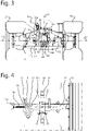
- the swing axle 11 is not configured as a bar or the like, but is configured more like a framework, as can clearly be seen particularly in Figure 3.
- Figure 3 furthermore shows that the swing axle 11 is movably coupled to a frame 13 of the vehicle 1 by means of a ball hinge 14.
- the ball 14a of the ball hinge 14 is arranged on a bottom crossbeam 11a of the swing axle 11, and the ball holder 14b is arranged on a frame beam 13a which extends substantially in the longitudinal direction of the vehicle 1.
- a holder arm 15 is provided which extends from the frame 13 and engages with a top crossbeam 11b.
- the swing axle 11 is movable about a swing axis 16 through the ball hinge 14 in order to perform a swinging movement, that is to say, a movement which is related to an upward movement of the one wheel 10 and a related downward movement of the other wheel 10, and which typically occurs when the vehicle 1 is moved across uneven terrain.
- the swing axis 16 extends in a direction at right angles to rotation axes 17 of the wheels 10.
- the swing axle 11 is movable about a steering axis 18 through the ball hinge 14 in order to perform a steering movement.
- the steering axis 18 extends in a direction at right angles to both the swing axis 16 and the rotation axes 17 of the wheels 10.
- the three aforementioned axes 16, 17, 18 are illustrated in Figure 3 .
- a steering movement may be achieved by driving the one wheel 10 at a higher speed than the other wheel 10.
- the swing axle 11 rotates about the steering axis 18 during a steering movement, with the ball 14a of the ball hinge 14 rotating in the ball holder 14b and a coupling portion 11c of the top crossbeam 11b of the swing axle 11 rotating in the holder arm 15.
- the holder arm 15 is movable with respect to the frame 13 about an axis which runs parallel to the steering axis.
- the holder arm 15 has a function in allowing the swinging movement and the steering movement of the swing axle 11 and in preventing a movement of the swing axle 11 about an axis through the ball hinge 14 which runs parallel to the rotation axes 17 of the wheels 10.
- the vehicle 1 comprises a stabilizing mechanism 20 which is coupled to the frame 13 and which is configured to keep the swing axle 11 in a defined rest swing position below a threshold value for a difference in pressure of the wheels 10 on the ground.
- this rest swing position is a position of the swing axle 11 in which it extends in a direction at right angles to the steering axis 18. Starting from a situation in which the vehicle 1 is situated on a horizontal, flat terrain, this is a horizontal direction.
- the stabilizing mechanism 20 may be configured in any suitable way.
- An advantage of the use of such a stabilizing mechanism 20 is the fact that rolling of the vehicle 1 during travel over uneven terrain is reduced compared to a situation where the vehicle 1 is not equipped with said mechanism. Only when the vehicle 1 travels over uneven objects which cause a difference in pressure of the wheels 10 on the ground above a certain threshold value, is the swing axle 11 released to perform a swinging movement, whereas the swing rest position of the swing axle 11 is maintained with smaller uneven objects. Reducing the rolling of the vehicle 1 may be desirable for various reasons, for example in order to cause minimal disruption to the performance of a navigation system.
- the stabilizing mechanism 20 comprises a stabilizing element 21 which is coupled to the frame 13 and is movable with respect to the frame 13 about an axis which runs parallel to the steering axis 18.
- the stabilizing element 21 is provided with an opening 22 with a design which aims at maintaining the swing rest position of the swing axle 11 as long as the difference in pressure of the wheels on the ground is below the threshold value and to allow the swinging movement of the swing axle 11 which takes place at a higher difference of pressure of the wheels on the ground to take place in a defined manner and in this case to also determine a maximum angular displacement of the swing axle 11 about the swing axis 16 with respect to the rest swing position, in two directions about the swing axis 16.
- the holder arm 15 is provided with an extended portion 15a in which a roller 19 is accommodated, the roller 19 being rotatable about an axis which runs parallel to the steering axis 18.
- This roller 19 runs against a guiding surface 23 of the stabilizing element 21, wherein the guiding surface 23 is a portion of the surface of the stabilizing element 21 which surrounds the opening 22.
- a pressure spring 24 is provided which extends from the frame 13 and presses against the stabilizing element 21, in a direction towards the holder arm 15.
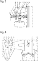
- Figures 4-8 serve to illustrate the swing rest position and a swung position of the swing axle 11.
- Figures 4 and 5 relate to the swing rest position of the swing axle 11 and show how, in this position, the holder arm 15 extends substantially in the longitudinal direction 6 of the vehicle 1, and how the roller 19 is positioned on the guiding surface 23.
- the guiding surface 23 has a generally V-shaped configuration, with the swing axle 11 being in the swing rest position when the roller 19 is situated in the deepest part of the V-shape.
- the deepest part of the V-shape forms a relatively narrow central portion of the guiding surface 23 which is configured to hold the roller 19 in a shape-determined manner.
- the design of the guiding surface 23 contributes to maintaining the swing rest position of the swing axle 11 when the difference in pressure of the wheels 10 on a ground is below the threshold value.
- Figure 6 illustrates how the swing axle 11 can assume a swung position from the swing rest position.
- the swing axle 11 and the wheels 10 in the swing rest position are indicated by solid lines, whereas the swing axle 11 and the wheels 10 in the swung position are indicated by dashed lines.
- the angular displacement of the swing axle 11 about the swing axis 16 is indicated by means of a curved arrow 16a.
- Figures 7 and 8 relate to the swung position of the swing axle 11 and show how, in this position, the holder arm 15 extends at an angle with respect to the longitudinal direction 6 of the vehicle 1, with the holder arm 15 being pulled towards the wheel 10 in the lowest position, as it were, and how the roller 19 is positioned on the guiding surface 23.
- the roller 19 has been moved out of the deepest portion via one of the legs of the V-shape until it reached a delimitation of the opening 22.
- the illustrated swung position is thus a maximum swung position in the direction about the swing axis 16 which is shown in Figure 6 .
- the exact shape of the guiding surface 23 may be chosen in such a way, that a desired relationship between the difference in pressure of the wheels 10 on the ground and the angular displacement of the swing axle 11 about the swing axis 16 is achieved, in which case then the force/displacement curve of the pressure spring 24 has been taken into account.
Landscapes
- Engineering & Computer Science (AREA)
- Mechanical Engineering (AREA)
- Chemical & Material Sciences (AREA)
- Combustion & Propulsion (AREA)
- Transportation (AREA)
- Life Sciences & Earth Sciences (AREA)
- Environmental Sciences (AREA)
- Vehicle Body Suspensions (AREA)
Claims (13)
- Autonomes und selbstfahrendes Fahrzeug (1) für unebenes Gelände, Folgendes umfassend:- ein Gestell (13), an dem sich ein Kugelgelenk (14) befindet,- ein Paar einzeln angetriebener Räder (10) und eine Pendelachse (11), an der die Räder (10) angebracht sind, wobei die Pendelachse (11) durch das Kugelgelenk (14) um eine Pendelachse (16) beweglich ist, um eine Pendelbewegung auszuführen, wobei sich die Pendelachse (16) in einer Richtung in rechten Winkeln zu Drehachsen (17) der Räder (10) erstreckt und wobei die Pendelachse (11) durch das Kugelgelenk (14) außerdem um eine Lenkachse (18) beweglich ist, um eine Lenkbewegung auszuführen, wobei sich die Lenkachse (18) in eine Richtung in rechten Winkeln zu sowohl der Pendelachse (16) als auch den Drehachsen (17) der Räder (10) erstreckt, und- einen Stabilisierungsmechanismus (20), der mit dem Gestell (13) gekoppelt und dafür gestaltet ist, die Pendelachse (11) in einer definierten Ruhependelposition unter einem Grenzwert für eine Differenz des Drucks der Räder (10) auf den Boden zu halten,wobei der Stabilisierungsmechanismus (20) Vorspannmittel (24) umfasst, die dafür gestaltet sind, die Pendelachse (11) durch Ausüben einer Vorspannkraft auf die Pendelachse (11) in die definierte Ruhependelposition vorzuspannen,
dadurch gekennzeichnet, dass
der Stabilisierungsmechanismus (20) ein Stabilisierungselement (21) umfasst, das mit dem Gestell (13) gekoppelt ist und im Verhältnis zu dem Gestell (13) um eine Achse beweglich ist, die parallel zur Lenkachse (18) verläuft, wobei das Stabilisierungselement (21) eine Führungsfläche (23) aufweist und wobei die Vorspannmittel (24) dafür gestaltet sind, die Führungsfläche (23) gegen ein Nachlaufelement (19) zu spannen, das mit der Pendelachse (11) gekoppelt ist. - Fahrzeug (1) nach Anspruch 1, wobei der Stabilisierungsmechanismus (20) des Weiteren dafür gestaltet ist, eine Pendelbewegung der Pendelachse (11) über dem Grenzwert für eine Differenz des Drucks der Räder (10) auf den Boden bei einem definierten Verhältnis für eine Differenz des Drucks der Räder (10) auf den Boden und einer Winkelverlagerung der Pendelachse (11) um die Pendelachse (16) im Verhältnis zur Ruhependelposition zu ermöglichen.
- Fahrzeug (1) nach Anspruch 1 oder 2, wobei der Stabilisierungsmechanismus (20) des Weiteren dafür gestaltet ist, eine maximale Winkelverlagerung der Pendelachse (11) um die Pendelachse (16) im Verhältnis zur Ruhependelposition in zwei Richtungen um die Pendelachse (16) zu bestimmen.
- Fahrzeug (1) nach einem der Ansprüche 1 bis 3, wobei die Vorspannmittel (24) mindestens ein Federmittel umfassen.
- Fahrzeug (1) nach einem der Ansprüche 1 bis 4, wobei das Nachlaufelement (19) eine Rolle ist, die um eine Achse drehbar ist, die parallel zur Lenkachse (18) verläuft.
- Fahrzeug (1) nach einem der Ansprüche 1 bis 5, wobei das Stabilisierungselement (21) eine Öffnung (22) enthält, und wobei die Führungsfläche (23) ein Abschnitt der Fläche des Stabilisierungselements (21) ist, welche die Öffnung (22) umgibt.
- Fahrzeug (1) nach einem der Ansprüche 1 bis 6, wobei die Führungsfläche (23) einen relativ schmalen mittleren Abschnitt aufweist, der dafür gestaltet ist, das Nachlaufelement (19) in einer formbestimmten Weise zu halten, wenn sich die Pendelachse (11) in der Ruhependelposition befindet, und eine Gestaltung aufweist, die im Allgemeinen von dem mittleren Abschnitt aus auseinanderläuft.
- Fahrzeug (1) nach einem der Ansprüche 1 bis 7, wobei die Führungsfläche (23) eine im Allgemeinen V-förmige Gestaltung aufweist.
- Fahrzeug (1) nach einem der Ansprüche 1 bis 8, wobei eine Form von jedem von zwei Abschnitten der Führungsfläche (23), die dafür gestaltet sind, das Nachlaufelement (19) während einer Winkelverlagerung der Pendelachse (11) um die Pendelachse (16) im Verhältnis zur Ruhependelposition zu führen, dafür eingerichtet ist, in Kombination mit einer Kraft-Verlagerung-Kurve der Vorspannmittel (24) eine im Wesentlichen konstante Differenz des Drucks der Räder (10) auf den Boden zu erzeugen.
- Fahrzeug (1) nach einem der Ansprüche 1 bis 9, einen Haltearm (15) umfassend, der mit dem Gestell (13) gekoppelt ist und im Verhältnis zum Gestell (13) um eine Achse beweglich ist, die parallel zur Lenkachse (18) verläuft, wobei die Pendelachse (11) an den Haltearm (15) gekoppelt und im Verhältnis zum Haltearm (15) um die Lenkachse (18) beweglich ist.
- Fahrzeug (1) nach Anspruch 10, wobei der Stabilisierungsmechanismus (20) mit dem Haltearm (15) in Eingriff steht.
- Fahrzeug (1) nach Anspruch 10, wenn abhängig von einem der Ansprüche 1 bis 9, wobei der Stabilisierungsmechanismus (20) mit dem Haltearm (15) in Eingriff steht und wobei sich das Nachlaufelement (19) an dem Haltearm (15) befindet.
- Fahrzeug (1) nach einem der Ansprüche 1 bis 12, wobei das Fahrzeug (1) einen Schneidemechanismus (2) und/oder einen Mechanismus (3), der dafür gestaltet ist, abgeschnittene Pflanzen aufzusammeln, umfasst.
Applications Claiming Priority (1)
| Application Number | Priority Date | Filing Date | Title |
|---|---|---|---|
| NL2023388A NL2023388B1 (nl) | 2019-06-26 | 2019-06-26 | Voertuig met een pendelas en een stabilisatiemechanisme voor de pendelas |
Publications (2)
| Publication Number | Publication Date |
|---|---|
| EP3756911A1 EP3756911A1 (de) | 2020-12-30 |
| EP3756911B1 true EP3756911B1 (de) | 2022-04-20 |
Family
ID=67742906
Family Applications (1)
| Application Number | Title | Priority Date | Filing Date |
|---|---|---|---|
| EP20181742.6A Active EP3756911B1 (de) | 2019-06-26 | 2020-06-23 | Fahrzeug mit schwingachse und stabilisierungsmechanismus für die schwingachse |
Country Status (2)
| Country | Link |
|---|---|
| EP (1) | EP3756911B1 (de) |
| NL (1) | NL2023388B1 (de) |
Family Cites Families (8)
| Publication number | Priority date | Publication date | Assignee | Title |
|---|---|---|---|---|
| US3155397A (en) * | 1962-02-12 | 1964-11-03 | Danimler Benz Ag | Double axle suspension and steering arrangement |
| DE2713331C2 (de) * | 1977-03-25 | 1982-05-06 | Süd-Chemie AG, 8000 München | Rollgestell |
| GB2265874B (en) * | 1992-04-10 | 1996-01-31 | Andrew Charles Nicol | Steering systems |
| US5447321A (en) * | 1994-07-08 | 1995-09-05 | New Holland North America, Inc. | Oscillation stop mechanism for compact tractors |
| FR2839937B1 (fr) * | 2002-05-21 | 2004-12-17 | Pascal Godfrind | Engin du type agricole ou de chantier tracte |
| GB2392657B (en) * | 2002-09-07 | 2006-03-08 | Agco Sa | Compound steering mechanism |
| DE102015117585A1 (de) * | 2015-10-15 | 2017-04-20 | Martin Brielmaier | Selbstfahrende Ballenpresse |
| WO2019197012A1 (en) * | 2018-04-09 | 2019-10-17 | Vitirover | Stop element for a robot having a chassis and a free rear axle housing with two axes of rotation with respect to the chassis |
-
2019
- 2019-06-26 NL NL2023388A patent/NL2023388B1/nl not_active IP Right Cessation
-
2020
- 2020-06-23 EP EP20181742.6A patent/EP3756911B1/de active Active
Also Published As
| Publication number | Publication date |
|---|---|
| EP3756911A1 (de) | 2020-12-30 |
| NL2023388B1 (nl) | 2021-02-01 |
Similar Documents
| Publication | Publication Date | Title |
|---|---|---|
| EP3740619B1 (de) | Sandbunkerrechen/ackerpflegefahrzeug | |
| EP3075569B1 (de) | Tragrahmen für landwirtschaftliche fahrzeuge | |
| CA2783807C (en) | Swather tractor with rear wheel active steering | |
| US9168784B2 (en) | Self-propelled windrower tailwheel non-zero caster for stability | |
| US20080035394A1 (en) | Drive wheel steering system for lawnmower | |
| EP3055194B1 (de) | Anordnung für ein geländekraftfahrzeug und geländekraftfahrzeug mit solch einer anordnung | |
| MXPA03004859A (es) | Mecanismo de alineacion de ruedas de vehiculo articulado. | |
| US7971886B2 (en) | Steering for towed implements | |
| JP2018082667A (ja) | 作業機 | |
| EP3756911B1 (de) | Fahrzeug mit schwingachse und stabilisierungsmechanismus für die schwingachse | |
| US20110001299A1 (en) | Vehicle having an axle capable of pendulum motion | |
| US4914894A (en) | Short turn implement or vehicle | |
| US7735574B2 (en) | Motor grader with adjustable front wheel structure | |
| US5295553A (en) | Rear wheel steerable working vehicle | |
| NO791901L (no) | Gressklipper. | |
| JP6220281B2 (ja) | クローラ式不整地作業車両 | |
| JP2015147552A (ja) | クローラ式不整地作業車両 | |
| EP4260677B1 (de) | Roboterrasenmäher mit antriebsrädern zur erkennung eines hindernisses | |
| JP2004330918A (ja) | 乗用田植機 | |
| CN211223596U (zh) | 一种自适应转向小车 | |
| US8578690B2 (en) | Haymaking machine provided with a hitching device with an inclined pivoting axis | |
| JP4670086B2 (ja) | 移植機 | |
| EP3061670B1 (de) | Vorrichtung zum aufbringen einer lenkung auf einen lenkrollensatz eines sattelaufliegers | |
| JP2015147554A (ja) | クローラ式不整地作業車両 | |
| JP2020025498A (ja) | 自律制御型草刈機 |
Legal Events
| Date | Code | Title | Description |
|---|---|---|---|
| PUAI | Public reference made under article 153(3) epc to a published international application that has entered the european phase |
Free format text: ORIGINAL CODE: 0009012 |
|
| STAA | Information on the status of an ep patent application or granted ep patent |
Free format text: STATUS: THE APPLICATION HAS BEEN PUBLISHED |
|
| AK | Designated contracting states |
Kind code of ref document: A1 Designated state(s): AL AT BE BG CH CY CZ DE DK EE ES FI FR GB GR HR HU IE IS IT LI LT LU LV MC MK MT NL NO PL PT RO RS SE SI SK SM TR |
|
| AX | Request for extension of the european patent |
Extension state: BA ME |
|
| STAA | Information on the status of an ep patent application or granted ep patent |
Free format text: STATUS: REQUEST FOR EXAMINATION WAS MADE |
|
| 17P | Request for examination filed |
Effective date: 20210630 |
|
| RBV | Designated contracting states (corrected) |
Designated state(s): AL AT BE BG CH CY CZ DE DK EE ES FI FR GB GR HR HU IE IS IT LI LT LU LV MC MK MT NL NO PL PT RO RS SE SI SK SM TR |
|
| GRAP | Despatch of communication of intention to grant a patent |
Free format text: ORIGINAL CODE: EPIDOSNIGR1 |
|
| STAA | Information on the status of an ep patent application or granted ep patent |
Free format text: STATUS: GRANT OF PATENT IS INTENDED |
|
| RIC1 | Information provided on ipc code assigned before grant |
Ipc: B62D 9/00 20060101ALI20211031BHEP Ipc: A01D 67/00 20060101ALI20211031BHEP Ipc: A01D 43/063 20060101ALI20211031BHEP Ipc: A01B 69/04 20060101ALI20211031BHEP Ipc: B62D 7/04 20060101ALI20211031BHEP Ipc: A01D 41/02 20060101ALI20211031BHEP Ipc: B60G 11/16 20060101ALI20211031BHEP Ipc: B60G 1/04 20060101ALI20211031BHEP Ipc: B60G 9/02 20060101AFI20211031BHEP |
|
| INTG | Intention to grant announced |
Effective date: 20211116 |
|
| RIN1 | Information on inventor provided before grant (corrected) |
Inventor name: VERWEIJ, ROCHUS JOHANNES Inventor name: VISSER, AREND CORNELIS Inventor name: DE JONG, RUTH |
|
| GRAS | Grant fee paid |
Free format text: ORIGINAL CODE: EPIDOSNIGR3 |
|
| GRAA | (expected) grant |
Free format text: ORIGINAL CODE: 0009210 |
|
| STAA | Information on the status of an ep patent application or granted ep patent |
Free format text: STATUS: THE PATENT HAS BEEN GRANTED |
|
| AK | Designated contracting states |
Kind code of ref document: B1 Designated state(s): AL AT BE BG CH CY CZ DE DK EE ES FI FR GB GR HR HU IE IS IT LI LT LU LV MC MK MT NL NO PL PT RO RS SE SI SK SM TR |
|
| REG | Reference to a national code |
Ref country code: GB Ref legal event code: FG4D |
|
| REG | Reference to a national code |
Ref country code: CH Ref legal event code: EP |
|
| REG | Reference to a national code |
Ref country code: IE Ref legal event code: FG4D |
|
| REG | Reference to a national code |
Ref country code: DE Ref legal event code: R096 Ref document number: 602020002730 Country of ref document: DE |
|
| REG | Reference to a national code |
Ref country code: AT Ref legal event code: REF Ref document number: 1484905 Country of ref document: AT Kind code of ref document: T Effective date: 20220515 |
|
| REG | Reference to a national code |
Ref country code: NL Ref legal event code: FP |
|
| REG | Reference to a national code |
Ref country code: LT Ref legal event code: MG9D |
|
| REG | Reference to a national code |
Ref country code: AT Ref legal event code: MK05 Ref document number: 1484905 Country of ref document: AT Kind code of ref document: T Effective date: 20220420 |
|
| PG25 | Lapsed in a contracting state [announced via postgrant information from national office to epo] |
Ref country code: SE Free format text: LAPSE BECAUSE OF FAILURE TO SUBMIT A TRANSLATION OF THE DESCRIPTION OR TO PAY THE FEE WITHIN THE PRESCRIBED TIME-LIMIT Effective date: 20220420 Ref country code: PT Free format text: LAPSE BECAUSE OF FAILURE TO SUBMIT A TRANSLATION OF THE DESCRIPTION OR TO PAY THE FEE WITHIN THE PRESCRIBED TIME-LIMIT Effective date: 20220822 Ref country code: NO Free format text: LAPSE BECAUSE OF FAILURE TO SUBMIT A TRANSLATION OF THE DESCRIPTION OR TO PAY THE FEE WITHIN THE PRESCRIBED TIME-LIMIT Effective date: 20220720 Ref country code: LT Free format text: LAPSE BECAUSE OF FAILURE TO SUBMIT A TRANSLATION OF THE DESCRIPTION OR TO PAY THE FEE WITHIN THE PRESCRIBED TIME-LIMIT Effective date: 20220420 Ref country code: HR Free format text: LAPSE BECAUSE OF FAILURE TO SUBMIT A TRANSLATION OF THE DESCRIPTION OR TO PAY THE FEE WITHIN THE PRESCRIBED TIME-LIMIT Effective date: 20220420 Ref country code: GR Free format text: LAPSE BECAUSE OF FAILURE TO SUBMIT A TRANSLATION OF THE DESCRIPTION OR TO PAY THE FEE WITHIN THE PRESCRIBED TIME-LIMIT Effective date: 20220721 Ref country code: FI Free format text: LAPSE BECAUSE OF FAILURE TO SUBMIT A TRANSLATION OF THE DESCRIPTION OR TO PAY THE FEE WITHIN THE PRESCRIBED TIME-LIMIT Effective date: 20220420 Ref country code: ES Free format text: LAPSE BECAUSE OF FAILURE TO SUBMIT A TRANSLATION OF THE DESCRIPTION OR TO PAY THE FEE WITHIN THE PRESCRIBED TIME-LIMIT Effective date: 20220420 Ref country code: BG Free format text: LAPSE BECAUSE OF FAILURE TO SUBMIT A TRANSLATION OF THE DESCRIPTION OR TO PAY THE FEE WITHIN THE PRESCRIBED TIME-LIMIT Effective date: 20220720 Ref country code: AT Free format text: LAPSE BECAUSE OF FAILURE TO SUBMIT A TRANSLATION OF THE DESCRIPTION OR TO PAY THE FEE WITHIN THE PRESCRIBED TIME-LIMIT Effective date: 20220420 |
|
| PG25 | Lapsed in a contracting state [announced via postgrant information from national office to epo] |
Ref country code: RS Free format text: LAPSE BECAUSE OF FAILURE TO SUBMIT A TRANSLATION OF THE DESCRIPTION OR TO PAY THE FEE WITHIN THE PRESCRIBED TIME-LIMIT Effective date: 20220420 Ref country code: PL Free format text: LAPSE BECAUSE OF FAILURE TO SUBMIT A TRANSLATION OF THE DESCRIPTION OR TO PAY THE FEE WITHIN THE PRESCRIBED TIME-LIMIT Effective date: 20220420 Ref country code: LV Free format text: LAPSE BECAUSE OF FAILURE TO SUBMIT A TRANSLATION OF THE DESCRIPTION OR TO PAY THE FEE WITHIN THE PRESCRIBED TIME-LIMIT Effective date: 20220420 Ref country code: IS Free format text: LAPSE BECAUSE OF FAILURE TO SUBMIT A TRANSLATION OF THE DESCRIPTION OR TO PAY THE FEE WITHIN THE PRESCRIBED TIME-LIMIT Effective date: 20220820 |
|
| REG | Reference to a national code |
Ref country code: DE Ref legal event code: R097 Ref document number: 602020002730 Country of ref document: DE |
|
| PG25 | Lapsed in a contracting state [announced via postgrant information from national office to epo] |
Ref country code: SM Free format text: LAPSE BECAUSE OF FAILURE TO SUBMIT A TRANSLATION OF THE DESCRIPTION OR TO PAY THE FEE WITHIN THE PRESCRIBED TIME-LIMIT Effective date: 20220420 Ref country code: SK Free format text: LAPSE BECAUSE OF FAILURE TO SUBMIT A TRANSLATION OF THE DESCRIPTION OR TO PAY THE FEE WITHIN THE PRESCRIBED TIME-LIMIT Effective date: 20220420 Ref country code: RO Free format text: LAPSE BECAUSE OF FAILURE TO SUBMIT A TRANSLATION OF THE DESCRIPTION OR TO PAY THE FEE WITHIN THE PRESCRIBED TIME-LIMIT Effective date: 20220420 Ref country code: MC Free format text: LAPSE BECAUSE OF FAILURE TO SUBMIT A TRANSLATION OF THE DESCRIPTION OR TO PAY THE FEE WITHIN THE PRESCRIBED TIME-LIMIT Effective date: 20220420 Ref country code: EE Free format text: LAPSE BECAUSE OF FAILURE TO SUBMIT A TRANSLATION OF THE DESCRIPTION OR TO PAY THE FEE WITHIN THE PRESCRIBED TIME-LIMIT Effective date: 20220420 Ref country code: DK Free format text: LAPSE BECAUSE OF FAILURE TO SUBMIT A TRANSLATION OF THE DESCRIPTION OR TO PAY THE FEE WITHIN THE PRESCRIBED TIME-LIMIT Effective date: 20220420 Ref country code: CZ Free format text: LAPSE BECAUSE OF FAILURE TO SUBMIT A TRANSLATION OF THE DESCRIPTION OR TO PAY THE FEE WITHIN THE PRESCRIBED TIME-LIMIT Effective date: 20220420 |
|
| REG | Reference to a national code |
Ref country code: BE Ref legal event code: MM Effective date: 20220630 |
|
| PLBE | No opposition filed within time limit |
Free format text: ORIGINAL CODE: 0009261 |
|
| STAA | Information on the status of an ep patent application or granted ep patent |
Free format text: STATUS: NO OPPOSITION FILED WITHIN TIME LIMIT |
|
| 26N | No opposition filed |
Effective date: 20230123 |
|
| PG25 | Lapsed in a contracting state [announced via postgrant information from national office to epo] |
Ref country code: AL Free format text: LAPSE BECAUSE OF FAILURE TO SUBMIT A TRANSLATION OF THE DESCRIPTION OR TO PAY THE FEE WITHIN THE PRESCRIBED TIME-LIMIT Effective date: 20220420 |
|
| PG25 | Lapsed in a contracting state [announced via postgrant information from national office to epo] |
Ref country code: LU Free format text: LAPSE BECAUSE OF NON-PAYMENT OF DUE FEES Effective date: 20220623 Ref country code: IE Free format text: LAPSE BECAUSE OF NON-PAYMENT OF DUE FEES Effective date: 20220623 |
|
| PG25 | Lapsed in a contracting state [announced via postgrant information from national office to epo] |
Ref country code: SI Free format text: LAPSE BECAUSE OF FAILURE TO SUBMIT A TRANSLATION OF THE DESCRIPTION OR TO PAY THE FEE WITHIN THE PRESCRIBED TIME-LIMIT Effective date: 20220420 Ref country code: BE Free format text: LAPSE BECAUSE OF NON-PAYMENT OF DUE FEES Effective date: 20220630 |
|
| P01 | Opt-out of the competence of the unified patent court (upc) registered |
Effective date: 20230425 |
|
| REG | Reference to a national code |
Ref country code: DE Ref legal event code: R084 Ref document number: 602020002730 Country of ref document: DE |
|
| PG25 | Lapsed in a contracting state [announced via postgrant information from national office to epo] |
Ref country code: IT Free format text: LAPSE BECAUSE OF FAILURE TO SUBMIT A TRANSLATION OF THE DESCRIPTION OR TO PAY THE FEE WITHIN THE PRESCRIBED TIME-LIMIT Effective date: 20220420 |
|
| REG | Reference to a national code |
Ref country code: CH Ref legal event code: PL |
|
| PG25 | Lapsed in a contracting state [announced via postgrant information from national office to epo] |
Ref country code: MK Free format text: LAPSE BECAUSE OF FAILURE TO SUBMIT A TRANSLATION OF THE DESCRIPTION OR TO PAY THE FEE WITHIN THE PRESCRIBED TIME-LIMIT Effective date: 20220420 Ref country code: CY Free format text: LAPSE BECAUSE OF FAILURE TO SUBMIT A TRANSLATION OF THE DESCRIPTION OR TO PAY THE FEE WITHIN THE PRESCRIBED TIME-LIMIT Effective date: 20220420 Ref country code: CH Free format text: LAPSE BECAUSE OF NON-PAYMENT OF DUE FEES Effective date: 20230630 |
|
| PG25 | Lapsed in a contracting state [announced via postgrant information from national office to epo] |
Ref country code: HU Free format text: LAPSE BECAUSE OF FAILURE TO SUBMIT A TRANSLATION OF THE DESCRIPTION OR TO PAY THE FEE WITHIN THE PRESCRIBED TIME-LIMIT; INVALID AB INITIO Effective date: 20200623 |
|
| PG25 | Lapsed in a contracting state [announced via postgrant information from national office to epo] |
Ref country code: MT Free format text: LAPSE BECAUSE OF FAILURE TO SUBMIT A TRANSLATION OF THE DESCRIPTION OR TO PAY THE FEE WITHIN THE PRESCRIBED TIME-LIMIT Effective date: 20220420 |
|
| PG25 | Lapsed in a contracting state [announced via postgrant information from national office to epo] |
Ref country code: BG Free format text: LAPSE BECAUSE OF FAILURE TO SUBMIT A TRANSLATION OF THE DESCRIPTION OR TO PAY THE FEE WITHIN THE PRESCRIBED TIME-LIMIT Effective date: 20220420 |
|
| PG25 | Lapsed in a contracting state [announced via postgrant information from national office to epo] |
Ref country code: BG Free format text: LAPSE BECAUSE OF FAILURE TO SUBMIT A TRANSLATION OF THE DESCRIPTION OR TO PAY THE FEE WITHIN THE PRESCRIBED TIME-LIMIT Effective date: 20220420 |
|
| PGFP | Annual fee paid to national office [announced via postgrant information from national office to epo] |
Ref country code: DE Payment date: 20250627 Year of fee payment: 6 |
|
| PGFP | Annual fee paid to national office [announced via postgrant information from national office to epo] |
Ref country code: GB Payment date: 20250627 Year of fee payment: 6 |
|
| PGFP | Annual fee paid to national office [announced via postgrant information from national office to epo] |
Ref country code: NL Payment date: 20250626 Year of fee payment: 6 |
|
| PGFP | Annual fee paid to national office [announced via postgrant information from national office to epo] |
Ref country code: FR Payment date: 20250625 Year of fee payment: 6 |
|
| PG25 | Lapsed in a contracting state [announced via postgrant information from national office to epo] |
Ref country code: TR Free format text: LAPSE BECAUSE OF FAILURE TO SUBMIT A TRANSLATION OF THE DESCRIPTION OR TO PAY THE FEE WITHIN THE PRESCRIBED TIME-LIMIT Effective date: 20220420 |